6112-00中文资料
中英文汽车零件对照表

60441-S84 -A000-50
C/MBR
前保险杠支撑横梁
60441-S84 -A002-H1
C/MBR,FR BHD LWR
前保险杠支撑横梁
6044A-S84 -A000
C/MBR FR BHD LWR SUB COMP
前保险杠支撑横梁预总成
60451-S84 -A000-50
左前轮罩分总成
60751-S84 -A000-50
HSG UP,L
左前悬挂上支承
60751-S84 -A001-H1
HOUSING UP L,FR DPR
左前悬挂上支承
60751-S84 -ZZ01-H1
DWG,FR DPR HOUSING UP L
左前悬挂上支承图
60752-S84 -A000-50
60632-S84 -A000-H1
STAY,BATTERY
蓄电池支撑
60632-S84 -ZZ00-H1
DWG,BATTERYSTAY
蓄电池支撑图
60651-S84 -A000-50
HSG UP,R
右前悬挂上支承
60651-S84 -A001-H1
HOUSING UP R,FR DPR
右前悬挂上支承
BRKT
隔板支架
60666-SA5 -3001
BRKT,BAFFLE PL
隔板支架
60700-S4T -A000-H1
WHEEL HOUSE COMP L,FRONT
左前轮罩总成
60711-S84 -A000-50
WHEEL HOUSE L
左前轮罩
60711-S84 -A002-H1
WHEEL HOUSE L, FRONT
86702-0000中文资料

• Versatile connector systemwith a RJ-45 form factor • Duplex ferrule• Increases port density required oncomputer and networking relatedhardware, panels, wall plates, and in closets by 50%• Meets TIA-568A standards • Low insertion loss:<.22 dB TYP MM <.19 dB TYP SMFeatures & Benefits Applications• Premise infrastructure- Backbone - Horizontal• Local Area Networks (LAN's)• Device terminations • Telecommunication networks The MT-RJ connector was developed to meet growing customer demands for smaller, lower cost, and easier-to-use fiber optic connectivity. The MT-RJ reduces the space required on panels, wall plates and in closets by 50% throughout the network.This small form factor connector is ideal for fiber-to-the-desk applications. The design meets TIA requirements.The MT-RJ uses an improved version of an industry standard RJ-45 type plug. This combination of a small form factor connector with the familiar RJ-45 latching mechanism ensures the MT-RJ connector to be the perfect choice for horizontal cabling needs to the desk-top.Products in the MT-RJ connector solution family will include: field mountable connectors, duplex patchcords, hybridpatchcords, pigtails, duplex adapters for MT-RJ cut-outs, as well as SC cut-outs, SixPaxs™ panels, hand polishing tooling,and consumable kits.The MT-RJ adapter occupies approximately the same space as a simplex SC adapter. When used in conjunction with the SixPaxs panel, the MT-RJ duplex adapter fits most LGX* style hardware, offering more user-friendly characteristics in high density applications.*LGX is a trademark of Lucent T echnologiesPerformance and SpecificationsConnectorMultimode Singlemode Nominal Fiber OD125µm 125µm Insertion Loss.22, .09 dB0.19, 06 dB(Average standard deviation)Return Loss (Minimum)20 dB45 dBCable Retention (Minimum)Exceeds 15 lbs. / 67N Exceeds 15 lbs. / 67N Mating Durability for 200 Reconnects <.05 dB<.03 dBInsertion Loss ChangeTemperature Stability (-40°C to +75°C)<.15 dB <.15 dBInsertion Loss Change Tip MaterialComposite CompositeMOLEX FIBER OPTICS DIVISION 5224 Katrine Avenue, Downers Grove, IL 60515 / Tel: 800-A1-FIBER or (630) 512-8787 Web: /fiber86002-3000MT-RJ connector, MM, male, beige boot86002-3400MT-RJ connector, MM, male, 90° beige boot86002-3030MT-RJ connector, MM, male, black boot86002-3430MT-RJ connector, MM, male, 90° black boot86003-3000MT-RJ connector, MM, female, beige boot86003-3400MT-RJ connector, MM, female, 90° beige boot86003-3030MT-RJ connector, MM, female, black boot86003-3430MT-RJ connector, MM, female, 90° black boot86002-5000MT-RJ connector, SM, male, blue boot86002-5400MT-RJ connector, SM, male, 90° blue boot86003-5000MT-RJ connector, SM, female, blue boot86003-5400MT-RJ connector, SM, female, 90° blue boot86102-0000MT-RJ adapter, standard MT-RJ cut-out86102-0100MT-RJ adapter, simplex SC cut-out with clip86702-0000MT-RJ tool kit (includes consumables)86800-3650MT-RJ adapter, SixPaxs TM86001-0083 Rev. 4 USA/30MFO/2000.09 ©2000, Molex Molex reserves the right to make any changes to the product(s) or information contained herein without notice. No liability is assumed as a result of their use or application.。
MS611-04中文

编制:校对:审核:批准:(标准号MS 611-04 第2页共8页)1.范围该标准确定了汽车上钢零部件抗腐蚀性及装饰用的电镀锌层的要求(下文中简称“镀层”)2.术语定义说明书上术语的应用应当符合KSD8317(电镀层中的术语表)并且其余的术语如下:(1)光亮镀层表面防腐蚀锌镀层是利用化学抛光的方式进行处理至于表面处理类型是利用烙酸盐液体表面处理,主要在于应用化学抛光的方法来保护镀层并且获得表面光亮的方法是抗腐蚀性镀层培育之后的碱性溶液。
(2)彩色、绿色、和黑色烙酸盐抗腐蚀性的厚烙酸层是彩色的,由于这个原因抗腐蚀性的烙酸层被命名为彩色烙酸盐。
变化的色彩取决于各种混和物的比例。
(xCr2O3、yCrO3、zH2O)(3)表面干涉带彩色带的产生是由于簿膜表面的白色反射和金属层所形成的干涉。
(4)表面变化色彩多变的彩色镀层主要取决于变化表面的影响,就如同非均匀色调将会导致同一零部件的同一表面很难获得确定的色彩。
(5)白色腐蚀层的产生当镀层被破坏之后,锌裸露在腐蚀环境之中形成锌腐蚀层,锌腐蚀层产物是由白色混和物组成。
诸如:锌碳酸盐和其它白色产物。
3.种类和代号汽车零部件镀锌层的种类和代号应当符合表格1表格1 种类和代号(标准号MS 611-04 第5页共8页)备注:1)符号B、C、D、G分别代表光亮、黄色、黑色、绿色的表面处理。
2)“内部”表示零部件内表面,不是直接或间接地裸露在风中或雨中部分。
3)“外部”也就是除了内部之外的部分。
如果有的部分被风化此部分应当被称作外部。
4.要求4.1 外观镀层表面应一致且美观不应当有伤痕、水泡、裸露部分并且应当避免其它可能影响到外观或保护层质量的因素。
白色和黄色的表面处理可能有干涉或不同的色彩但是黑色的表面处理不能有任何彩色的污染。
绿色的表面处理是不同于明或暗的色彩,但是不应当受到任何色彩的污染。
4.2 最小镀层厚度除了特殊的表面处理之外,最小镀层厚度如下表格2(标准号MS 611-04 第6页共8页)表格2 最小镀层厚度4.2 抗腐蚀性应当符合KSD 8304中5-3并且在表格3中裸露一段时间之后表面不得有锈蚀(白色污点或铁锈).表格3 盐水喷洒测试时间单位:小时(标准号MS 611-04 第7页共8页)4.4防氢脆性没有其它说明时,所有钢件(螺栓、螺丝、垫圈、弹性垫圈、弹簧卡片、销子及其它机械用零部件)在处理完之后8小时之后,应当为烙氏硬度C35或有更高淬火层和回火硬度。
霍曼卷帘门445R中文说明书

卷帘门/卷帘隔栅控制系统 S 和 K
445 R
TR25E097
内容
章节 0
页码 前视图 内容 .......................................................................... 0-2 445 R 控制系统内视图 .............................................. 0-4 连接视图 ................................................................... 0-5
7 7.1 7.2 7.3 7.4 7.5
附件及扩展附件 综述 .......................................................................... 7-1 底边保护装置 SKS .................................................... 7-2 光电保护 EZS ........................................................... 7-3 PCB终端信号 ............................................................ 7-4 多功能PCB ............................................................... 7-5
1 1.1 1.2 1.3 1.4 1.5 2 2.1 2.2 2.3 2.4
概述 介绍 .......................................................................... 1-1 版权 .......................................................................... 1-1 保修 .......................................................................... 1-1 操作说明的结构 ........................................................ 1-1 电缆和单股电线的颜色码 .......................................... 1-2 安全 概述 .......................................................................... 2-1 指定应用 ................................................................... 2-1 人身安全 ................................................................... 2-1 安全内容 (根据章节排列)........................................... 2-1
玉柴6112,6G国4系列柴油机的参数

Q/YC 587—2011 1 主要技术参数见表1。
表1表1(续)12 要求2.1 功率柴油机的标定功率应符合表1的规定,其偏差应不超过±5%。
最大净功率应符合表1的规定。
型式认证时, 其偏差应不大于±2%, 生产一致性时, 其偏差应不于±5%。
2.2 最大扭矩柴油机的最大扭矩应符合表1的规定,其偏差应不超过±6%。
2.3 油耗柴油机的最大扭矩工况燃油消耗率、外特性最低燃油消耗率和机油燃油消耗比应符合表1的规定。
2.4 温度和压力温度和压力应符合下列规定:a)机油温度(油底壳)为95℃~115℃;b)机油压力为0.3 MPa~0.6 Mpa;c)冷却水温度(出口)为75℃~95℃;d)排气温度(涡轮后)应不大于580℃。
怠速时机油压力应不低于0.1MPa。
2.5 各缸工作均匀性柴油机在标定工况运转时,各缸平均指示压力不均匀率应不大于4%。
2.6 最高空载转速柴油机最高空载转速应符合表1的规定,当柴油机的转速大于标定转速时,应能自动减少供油,而当柴油机的转速恢复到标定转速时, 应能自动恢复正常供油。
Q/YC 587—2011 2.7 最低空载转速柴油机最低空载转速应符合表1的规定, 在最低空载转速(怠速)运转时,应能稳定运行5min以上。
柴油机的怠速转速波动值应不超过±20r/min。
2.8 起动性柴油机在周围环境温度不低于—15℃时,不采用特殊低温起动措施应能顺利起动,起动所需时间不大于15s,连续起动三次, 有二次能起动均算成功,每次间隔应不小于2min。
当环境温度低于—15℃时, 允许用其它辅助起动措施。
2.9 安全性柴油机应装有紧急停车装置,且须灵活有效。
机油压力感应塞、低压报警器、水温感应塞应灵敏有效。
柴油机气泵应工作正常。
2.10 纵倾、横倾柴油机在纵倾20°、横倾20°的条件下应能正常地工作。
2.11 密封性经出厂检查合格的柴油机各密封面及管接处, 不允许漏气、漏油、漏水。
艾默生表面处理代码
艾默生网络能源有限公司检验标准名称:表面处理代码图号:DMBM0.402.022拟制:何浩审核:张士杰、徐建平标准化:詹轶群IQC会签:汪长华批准:张运清修订信息表目录表面处理代码 (5)1 目的 (5)2 适用范围 (5)3 关键词 (5)4 引用/参考标准或资料 (5)5 规范内容 (5)5.1 术语 (5)5.2 技术说明 (6)5.3 备注 (6)表面处理代码1 目的本标准规定了图纸中标注表面处理时所用的代码内容,并说明了每种工艺所对应的技术要求以及每种外观要求应采用的标准样板。
2 适用范围本标准适用于艾默生网络能源有限公司产品的结构件零件、组合件的设计及图纸标注和后续的采购、生产、检验。
3 关键词表面处理电镀喷漆粉末喷涂标准代码4 引用/参考标准或资料下列标准包含的条文,通过在本标准中引用而构成本标准的条文。
在标准出版时,所示版本均为有效。
所有标准都会被修订,使用本标准的各方应探讨使用下列标准最新版本的可能性。
DMBM0.402.003表面处理通用检验标准DMBM0.487.006 环氧玻璃布层压板检验标准DMBM0.402.001 产品表面外观缺陷的限定标准5 规范内容5.1 术语5.1.1 组合件:指用铆接、搭接、胶接、点焊、或压配合等类似方法组装在一起的部件。
5.1.2 无色阳极化:即无色硫酸阳极化(纯水封闭)。
5.1.3 光亮阳极化:即化学抛光后再进行无色硫酸阳极化处理。
5.1.4 喷砂光亮阳极化:即先喷砂再进行光亮阳极化处理。
5.1.5 黑色阳极化:即硫酸阳极化着黑色。
5.1.6 金黄色阳极化:即硫酸阳极化着金黄色。
5.1.7 喷砂光亮黑色阳极化:即先喷砂再进行化学抛光及黑色阳极化。
5.1.8 光亮无色化学氧化:即先化学抛光后再进行无色化学氧化处理。
5.1.9 喷砂光亮无色化学氧化:即先喷砂处理再进行光亮无色化学氧化。
5.2 技术说明5.2.1 表面处理代码以字母加数字表示。
0190020022;中文规格书,Datasheet资料

This document was generated on 08/13/2012PLEASE CHECK FOR LATEST PART INFORMATIONPart Number:19002-0022Status:ActiveDescription:Avikrimp™ Fully Insulated Quick Disconnect, Female, for 18-22 AWG Wire, Mylar TapeDocuments:Drawing (PDF)Product Specification PS-19902-015 (PDF)Product Specification PS-19902-011 (PDF)RoHS Certificate of Compliance (PDF)Product Specification PS-19902-014 (PDF)Agency CertificationTUV R75108ULE79133GeneralProduct Family Quick Disconnects Series19002Crimp Quality Equipment YesProduct Name Avikrimp™Type Quick Disconnect UPC800753027268PhysicalBarrel Type Closed Flammability 94V-2GenderFemale Glow-Wire Compliant NoInsulationNylon (PA)Lock to Mating Part None Material - Metal Brass Net Weight 0.862/g OrientationStraightPackaging TypeAdhesive Tape on Reel Polarized to Mating Part NoTab Thickness 0.81mm Tab Width5.21mmTemperature Range - Operating -65°C to +105°C Wire Insulation Diameter 3.17mm max.Wire Size AWG 18, 20, 22Wire Size mm²0.35 - 0.80ElectricalVoltage - Maximum300V Material InfoOld Part NumberAA-5285TReference - Drawing NumbersProduct Specification PS-19902-011, PS-19902-014, PS-19902-015Sales DrawingSD-19002-003Seriesimage - Reference onlyEU RoHSChina RoHSELV and RoHS Compliant REACH SVHCContains SVHC: No Low-Halogen Status Low-HalogenNeed more information on product environmental compliance?Email productcompliance@For a multiple part number RoHS Certificate of Compliance, click herePlease visit the Contact Us section for any non-product compliance questions.Search Parts in this Series 19002SeriesApplication Tooling | FAQTooling specifications and manuals are found by selecting the products below.Crimp Height Specifications are then contained in the Application Tooling Specification document.GlobalDescription Product #ATP Perishable Tool Kit Used in ATPPresses that Process Product on Tape 0192880028Mini-Mac™Applicator0638852000This document was generated on 08/13/2012PLEASE CHECK FOR LATEST PART INFORMATION/分销商库存信息: MOLEX 0190020022。
YC6G-20系列发动机操作和维护操作说明书_中英文_
While cleaning or replacing the oil filter element during the maintenance, it is shall be filled full of oil first before installation. After completion of installation you must start the engine and let it run at an idle speed, then get off the vehicle to see if there is any oil leakage in the oil filter. If yes, immediately remedy it; otherwise there will be lack of oil and the crankshaft wilents, and may speed up the abrasion of the diesel engine movable parts, resulting in short service life of the diesel engine. 4. 使用柴油机时要一档起步,不能拖档怠速。 Always use the first gear to start the engine, otherwise it will be stopped. 5. 应避免高速、大负荷运转状态下突然熄火停机,应逐渐降速、降负荷,怠速运转 5~10 分钟后再停机。 It shall be avoided to flameout the engine suddenly at high speed and heave load status. The speed and load shall be gradually reduced and the engine shall be in idle status for 5-10 minutes before complete stop. 6. 增压柴油机要按照说明书的要求严格控制好供油提前角。当柴油机功率下降时,应先检查进气管路是否 有漏气现象,空气滤清器是否已堵塞,并特别注意热态下空滤至增压器进气口之间的管路在突然加速时 有无被吸扁现象,然后再作进一步的调整或维修。 The fuel supply advance angle of the supercharging diesel engine shall be strictly controlled according to the specification. When there is powerlessness, firstly check if there is air leakage in the intake pipe, if the air filter is jammed and specially check if there is capitation on the piping between the air filter and the supercharger air intake inlet when suddenly speed up at heat status and then adjust and repair further. 7. 凡发现汽车及柴油机工作不正常时,要立即停车及时排除故障,绝不能让汽车带病运行。 Whenever the engine works abnormally, stop the auto and eliminate the failure in time and don¡t drive the auto with failures. 8. 检查发动机时,不要直接触摸发动机的高温部件(例如排气管),不要停机后马上打开水箱盖,以免烫伤。 While checking the engine, don¡t directly contact with the high temperature parts of the engine (like exhaust pipe) and don¡t open the water tank cover soon after the engine stopped in case of scald. 9. 凡新机运行达 1500~5000 公里时,须及时到玉柴的委托技术服务站进行走合保养,否则不予实行产品 的质量保修。 Whenever a new machine has run for 1,500-2,500km, it is necessary to send it to a mandatory technical service station of Yuchai for running-in maintenance; otherwise, free maintenance of your engine will be cancelled. 10. 柴油机在气温为-15℃~40℃,海拔高度为 2000 米以下的环境条件下能正常工作,禁止在水浸、水灾环 境下工作。在风沙大、粉尘多的环境下,应注意清理空气滤清器滤芯灰尘,滤芯如有破损应马上更换。 在气温低于-15℃、或气温高于 40℃、或海拔高度超过 2000 米时,用户应向玉柴技术、服务部门咨询, 采取有效措施以保证柴油机能正常工作。 The engine is applicable to circumstances where the ambient temperature is -15℃~40℃ and the elevation below 2,500m. It is prohibited to operate the engine in submerged or fire circumstances. Under sandy or dusty circumstance, remember to frequently clean the dust of the element of air cleaner. If the element is broken, immediately replace it with a new one of the same origin and specification. When the ambient temperature is below -15℃ or above 40℃ or the elevation exceeds 2,000m, you should consult with technical and service departments of Yuchai and then take effective measures to ensure normal work of the diesel engine.
46AS 1111.2-2000-《ISO米制六角头螺栓与螺钉-产品C级》第2部分:螺钉解析
Australian Standard TM《澳大利亚标准》TMISO metric hexagon bolts and screws—Product grade CPart 2: Screws《ISO米制六角头螺栓与螺钉-产品C级》第2部分:螺钉[ISO title: Hexagon head screws—Product grade C][ISO 名称:六角头螺钉-产品C级]This Australian Standard was prepared by Committee ME/29, Fasteners. It was approved on behalf of the Council of Standards Australia on 21 April 2000 and published on 23 June 2000.《澳大利亚标准》是由ME/29紧固件委员会编制的,并由该委员会代表澳大利亚标准委员会于2000年4月21日批准,于2000年6月23日出版。
The following interests are represented on Committee ME/29:ME/29委员会由以下单位参加:Australian Building Codes Board澳大利亚建筑标准委员会Australian Chamber of Commerce and Industry澳大利亚工商联合会Australian Industry Group澳大利亚工业团体Bureau of Steel Manufacturers of Australia澳大利亚钢铁制造局Electricity Supply Association of Australia澳大利亚电力供应协会Federal Chamber of Automotive Industries澳大利亚汽车工业联邦联合会Institute of Materials Engineering Australasia澳大利亚材料工程研究所Metal Building Products Manufacturers Association金属建筑产品制造商协会Keeping Standards up-to-date关于标准的更新Standards are living documents which reflect progress in science, technology and systems. To maintain their currency, all Standards are periodically reviewed, and new editions are published. Between editions, amendments may be issued. Standards may also be withdrawn. It is important that readers assure themselves they are using a current Standard, which should include any amendments which may have been published since the Standard was purchased.标准是应适时更新的文件体系,反映人们在科学、技术及系统方面取得的进步。
NS6112_设计指南
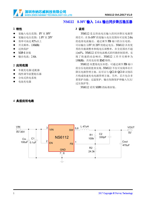
NS61128-30V输入2.6A输出同步降压稳压器1特性●宽输入电压范围:8V至30V ●宽输出电压范围:1.8V至28V ●效率可高达92%以上●开关频率:130kHz●过热保护●SOP-8封装●输出电流:2.6A2应用范围●车载充电器/适配器●线性调节前置稳压器●分布式供电系统●电池充电器3说明NS6112是支持高电压输入的同步降压电源管理芯片,在8~30V的宽输入电压范围内可实现2.6A 的连续电流输出。
通过调节FB端口的分压电阻,可以输出1.8V到28V的稳定电压。
NS6112具有优秀的负载调整率和线电压调整率,在全范围内不超过±3%。
NS6112采用电流模式的环路控制原理,实现了快速的动态响应。
NS6112工作开关频率为130kHz,具有良好的EMI特性。
NS6112内置线电压补偿,可通过调节FB端口的分压电阻阻值来实现。
NS6112不仅可实现单芯片降压电源管理方案,还可以与QC2.0/QC3.0识别芯片构成快速充电电源管理方案。
另外,芯片包含多重保护功能:过温保护,输出短路保护和输入欠压/过压保护等。
NS6112采用SOP8的标准封装。
4典型应用电路SOP-8的管脚图如下图所示:6极限工作参数●VIN 电压-0.3V ~33V ●FB 电压-0.3V ~33V ●SW 电压-0.3V ~33V ●EN 电压-0.3V ~33V ●工作温度范围-40℃~+85℃●存储温度范围-55℃~+150℃●结温范围+150℃●焊接温度(10s 内)+265℃注1:超过上述极限工作参数范围可能导致芯片永久性的损坏。
长时间暴露在上述任何极限条件下可能会影响芯片的可靠性和寿命。
注2:NS6112可以在0℃到70℃的限定范围内保证正常的工作状态。
超过-40℃至85℃温度范围的工作状态受设计和工艺控制影响。
编号管脚名称管脚描述管脚功能1FB反馈输入该管脚用于检测并设定输出电压;输出电压大小由R1和R2设定:V OUT =1.0V×[1+(R1/R2)]2EN 使能脚芯片使能脚,默认接VIN3VIN 电源供电管脚,该管脚应接至少100uF 电解电容到地,以避免输入端在工作时出现较大的电压波动4NC 5,6SW功率开关输出端该管脚为开关节点,与电感连接,用于负载功率输出7,8GND 地接地管脚8电气特性工作条件:T=25℃,V IN=12V,R1=100k,R2=24.3k符号参数名称条件最小值典型值最大值单位V IN工作电压范围830VI Q静态电流VIN=8V,EN=10V0.30.7mAI SHDN关断电流VIN=10V,EN=FB=0V3040uAV UVLO_H开启电压VIN接EN接FB 6.57.17.9V V UVLO_L关闭电压VIN接EN接FB 5.26 6.6mV V FB电压基准0.971 1.03Vf OSC振荡器频率130kHzDC最大占空比100% Icc最大恒定工作电流 2.6AI LIM最大峰值电流8AR DSP(ON)上管PMOSFET导通电阻80mΩR DSN(ON)下管NMOSFET导通电阻50mΩT SD过热关断温度150℃ΔT SD过热关断温度迟滞30℃9典型特性曲线下列特性曲线中,除非指定条件,T A=25℃,C IN=100uF,C OUT=470uF,L=47uH。
ASC2码

ascii编码Decimal Octal Hex Binary Value------- ----- --- ------ -----000 000 000 00000000 NUL (Null char.)001 001 001 00000001 SOH (Start of Header)002 002 002 00000010 STX (Start of Text)003 003 003 00000011 ETX (End of Text)004 004 004 00000100 EOT (End of Transmission)005 005 005 00000101 ENQ (Enquiry)006 006 006 00000110 ACK (Acknowledgment)007 007 007 00000111 BEL (Bell)008 010 008 00001000 BS (Backspace)009 011 009 00001001 HT (Horizontal Tab)010 012 00A 00001010 LF (Line Feed)011 013 00B 00001011 VT (Vertical Tab)012 014 00C 00001100 FF (Form Feed)013 015 00D 00001101 CR (Carriage Return)014 016 00E 00001110 SO (Shift Out)015 017 00F 00001111 SI (Shift In)016 020 010 ******** DLE (Data Link Escape)017 021 011 00010001 DC1 (XON) (Device Control 1)018 022 012 00010010 DC2 (Device Control 2)019 023 013 00010011 DC3 (XOFF)(Device Control 3)020 024 014 00010100 DC4 (Device Control 4)021 025 015 00010101 NAK (Negative Acknowledgement)022 026 016 00010110 SYN (Synchronous Idle)023 027 017 00010111 ETB (End of Trans. Block)024 030 018 00011000 CAN (Cancel)025 031 019 00011001 EM (End of Medium)026 032 01A 00011010 SUB (Substitute)027 033 01B 00011011 ESC (Escape)028 034 01C 00011100 FS (File Separator)029 035 01D 00011101 GS (Group Separator)030 036 01E 00011110 RS (Request to Send)(Record Separator)031 037 01F 00011111 US (Unit Separator)032 040 020 ******** SP (Space)033 041 021 ******** ! (exclamation mark)034 042 022 ******** " (double quote)035 043 023 ******** # (number sign)036 044 024 ******** $ (dollar sign)037 045 025 ******** % (percent)038 046 026 00100110 & (ampersand)039 047 027 ******** ' (single quote)040 050 028 ******** ( (left/opening parenthesis)041 051 029 ******** ) (right/closing parenthesis)042 052 02A 00101010 *(asterisk)043 053 02B 00101011 + (plus)044 054 02C 00101100 , (comma)045 055 02D 00101101 - (minus or dash)046 056 02E 00101110 . (dot)047 057 02F 00101111 / (forward slash)048 060 030 00110000 0049 061 031 00110001 1050 062 032 00110010 2051 063 033 00110011 3052 064 034 00110100 4053 065 035 00110101 5054 066 036 00110110 6055 067 037 00110111 7056 070 038 00111000 8057 071 039 00111001 9058 072 03A 00111010 : (colon)059 073 03B 00111011 ; (semi-colon)060 074 03C 00111100 <(less than)061 075 03D 00111101 = (equal sign)062 076 03E 00111110 > (greater than)063 077 03F 00111111 ? (question mark)064 100 040 01000000 @ (AT symbol)065 101 041 01000001 A066 102 042 01000010 B067 103 043 01000011 C068 104 044 01000100 D069 105 045 01000101 E070 106 046 01000110 F071 107 047 01000111 G072 110 048 01001000 H073 111 049 01001001 I074 112 04A 01001010 J075 113 04B 01001011 K076 114 04C 01001100 L077 115 04D 01001101 M078 116 04E 01001110 N079 117 04F 01001111 O080 120 050 01010000 P081 121 051 01010001 Q082 122 052 01010010 R083 123 053 01010011 S084 124 054 01010100 T085 125 055 01010101 U086 126 056 01010110 V087 127 057 01010111 W088 130 058 01011000 X089 131 059 01011001 Y090 132 05A 01011010 Z091 133 05B 01011011 [ (left/opening bracket)092 134 05C 01011100 \ (back slash)093 135 05D 01011101 ] (right/closing bracket)094 136 05E 01011110 ^ (caret/cirumflex)095 137 05F 01011111 _ (underscore)096 140 060 01100000 `097 141 061 01100001 a098 142 062 01100010 b099 143 063 01100011 c100 144 064 01100100 d 101 145 065 01100101 e 102 146 066 01100110 f 103 147 067 01100111 g 104 150 068 01101000 h 105 151 069 01101001 i 106 152 06A 01101010 j 107 153 06B 01101011 k 108 154 06C 01101100 l 109 155 06D 01101101 m 110 156 06E 01101110 n 111 157 06F 01101111 o 112 160 070 01110000 p 113 161 071 01110001 q 114 162 072 01110010 r 115 163 073 01110011 s 116 164 074 01110100 t 117 165 075 01110101 u 118 166 076 01110110 v 119 167 077 01110111 w 120 170 078 01111000 x 121 171 079 01111001 y122 172 07A 01111010 z123 173 07B 01111011 { (left/opening brace)124 174 07C 01111100 | (vertical bar)125 175 07D 01111101 } (right/closing brace)126 176 07E 01111110 ~ (tilde)127 177 07F 01111111 DEL (delete)前32个控制字符的详细解释:NUL (null)SOH (start of heading)STX (start of text)ETX (end of text)EOT (end of transmission) - Not the same as ETBENQ (enquiry)ACK (acknowledge)BEL (bell) - Caused teletype machines to ring a bell. Causes a beepin many common terminals and terminal emulation programs.BS (backspace) - Moves the cursor (or print head) move backwards (left)one space.TAB (horizontal tab) - Moves the cursor (or print head) right to the nexttab stop. The spacing of tab stops is dependenton the output device, but is often either 8 or 10.LF (NL line feed, new line) - Moves the cursor (or print head) to a newline. On Unix systems, moves to a new lineAND all the way to the left.VT (vertical tab)FF (form feed) - Advances paper to the top of the next page (if theoutput device is a printer).CR (carriage return) - Moves the cursor all the way to the left, but does not advance to the next line.SO (shift out) - Switches output device to alternate character set.SI (shift in) - Switches output device back to default character set. DLE (data link escape)DC1 (device control 1)DC2 (device control 2)DC3 (device control 3)DC4 (device control 4)NAK (negative acknowledge)SYN (synchronous idle)ETB (end of transmission block) - Not the same as EOTCAN (cancel)EM (end of medium)SUB (substitute)ESC (escape)FS (file separator) GS (group separator) RS (record separator) US (unit separator)。
兹公布於本局以编制外合同(首六个月试用期为散位合同)...
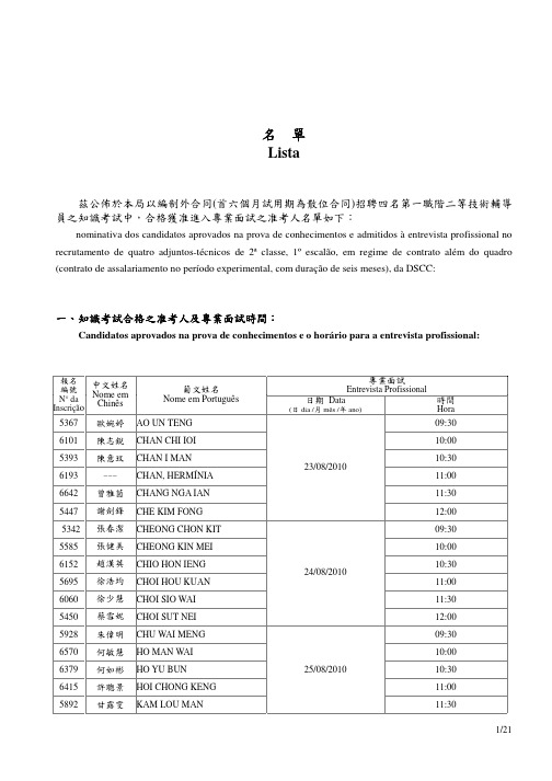
二、知識考試不合格而被淘汰之應考人: Candidatos excluídos por terem reprovado na prova de conhecimentos:
報名 編號
中文姓名
N° da Inscrição
Nome em Chinês
葡文姓名 Nome em Português
6738 歐澤林 AO CHAK LAM
6385 陳康利 CHAN HONG LEI
5935 陳綺文 CHAN I MAN
5523 陳貽禀 CHAN I PAN
5743 陳英東 CHAN IENG TONG
5917 陳耀陳 CHAN IO CHAN
6461 陳玉姸 CHAN IOK IN
5857 陳郁文 CHAN IOK MAN
6118 陳家欣 CHAN KA IAN
5652 張翠賢 CHEONG CHOI IN
5312 張頌衡 CHEONG CHONG HANG
5884 張鳳鳴 CHEONG FONG MENG
6590 張紅蓮 CHEONG HONG LIN
5508 張燕鋒 CHEONG IN FONG
6046 張燕萍 CHEONG IN PENG
6743 張嘉欣 CHEONG KA IAN
5777 陳子恆 CHAN CHI HANG
6600 陳芷凝 CHAN CHI IENG
5881 陳智衍 CHAN CHI IN
5248 陳志倫 CHAN CHI LON
5353 陳仲群 CHAN CHONG KUAN
5713 陳凱詩 CHAN HOI SI
6435 陳愷婷 CHAN HOI TENG
6716 周映兒 CHAO IENG I
XC6112E619资料
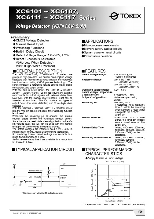
1/26XC6101_07_XC6111_17 ETR0207_009Preliminary◆CMOS Voltage Detector◆Manual Reset Input ◆Watchdog Functions ◆Built-in Delay Circuit ◆Detect Voltage Range: 1.6~5.0V, ± 2% ◆Reset Function is Selectable V DFL (Low When Detected) V DFH (High When Detected)■GENERAL DESCRIPTION The XC6101~XC6107, XC6111~XC6117 series aregroups of high-precision, low current consumption voltage detectors with manual reset input function and watchdog functions incorporating CMOS process technology. The series consist of a reference voltage source, delay circuit, comparator, and output driver.With the built-in delay circuit, the XC6101 ~ XC6107, XC6111 ~ XC6117 series’ ICs do not require any external components to output signals with release delay time. Moreover, with the manual reset function, reset can be asserted at any time. The ICs produce two types of output; V DFL (low when detected) and V DFH (high when detected).With the XC6101 ~ XC6105, XC6111 ~ XC6115 series’ ICs, the WD pin can be left open if the watchdog function is not used. Whenever the watchdog pin is opened, the internal counter clears before the watchdog timeout occurs. Since the manual reset pin is internally pulled up to the V IN pin voltage level, the ICs can be used with the manual reset pin left unconnected if the pin is unused.The detect voltages are internally fixed 1.6V ~ 5.0V in increments of 100mV, using laser trimming technology. Six watchdog timeout period settings are available in a range from 6.25msec to 1.6sec. Seven release delay time 1 are available in a range from 3.13msec to 1.6sec.■APPLICATIONS●Microprocessor reset circuits●Memory battery backup circuits ●System power-on reset circuits ●Power failure detection■TYPICAL APPLICATION CIRCUIT* Not necessary with CMOS output products.■FEATURESDetect Voltage Range: 1.6V ~ 5.0V, +2% (100mV increments)Hysteresis Range : V DF x 5%, TYP .(XC6101~XC6107)V DF x 0.1%, TYP .(XC6111~XC6117)Operating Voltage Range : 1.0V ~ 6.0V Detect Voltage Temperature Characteristics : +100ppm/O C (TYP .) Output Configuration : N-channel open drain,CMOSWatchdog Pin : Watchdog inputIf watchdog input maintains ‘H’ or ‘L’ within the watchdog timeout period, a reset signal is output to the RESET output pinManual Reset Pin : When driven ‘H’ to ‘L’levelsignal, the MRB pin voltage asserts forced reset on theoutput pin.Release Delay Time : 1.6sec, 400msec, 200msec,100msec, 50msec, 25msec, 3.13msec (TYP .) can be selectable.Watchdog Timeout Period : 1.6sec, 400msec, 200msec,100msec, 50msec,6.25msec (TYP .) can be selectable.■TYPICAL PERFORMANCE CHARACTERISTICS ●Supply Current vs. Input Voltage* ‘x’ represents both ‘0’ and ‘1’. (ex. XC61x1⇒XC6101 and XC6111)2/26XC6101~XC6107, XC6111~XC6117 SeriesPIN NUMBERXC6101, XC6102 XC6103 XC6104, XC6105XC6106, XC6107XC6111, XC6112 XC6113 XC6114, XC6115XC6116, XC6117SOT-25 USP-6C SOT-25 USP-6C SOT-25 USP-6C SOT-25USP-6CPIN NAMEFUNCTION1 4 - - 1 4 1 4 R ESETB Reset Output(V DFL : Low Level When Detected)2 5 2 5 2 5 2 5 V SSGround3 2 3 2 - -4 1 M RB ManualReset 4 1 4 1 4 1 - - WDWatchdog5 6 5 6 5 6 5 6 V IN Power Input - - 1 4 3 2 3 2 RESETReset Output (V DFH: High Level When Detected)■PIN CONFIGURATION SOT-25 (TOP VIEW)MRBV IN WD RESETBV SSMRBWD RESETV SSV IN RESETWD RESETBV SS V IN SOT-25 (TOP VIEW)RESETMRB RESETBV SS V IN SOT-25 (TOP VIEW) ■PIN ASSIGNMENT●SOT-25XC6101, XC6102 SeriesXC6111, XC6112 SeriesSOT-25 (TOP VIEW)XC6103 & XC6113 SeriesXC6104, XC6105 Series XC6114, XC6115 SeriesXC6106, XC6107 Series XC6116, XC6117 Series●USP-6CXC6101, XC6102 Series XC6111, XC6112 SeriesXC6103 & XC6113 SeriesXC6104, XC6105 Series XC6114, XC6115 SeriesXC6106, XC6107 Series XC6116, XC6117 SeriesUSP-6C (BOTTOM VIEW)USP-6C (BOTTOM VIEW)USP-6C (BOTTOM VIEW)USP-6C (BOTTOM VIEW)* The dissipation pad for the USP-6C package should be solder-plated in recommended mount pattern and metal masking so as to enhance mounting strength and heat release. If the pad needs to be connected to other pins, it should be connected to the V SS pin.3/26XC6101 ~ XC6107, XC6111~ XC6117SeriesRESET OUTPUTSERIES WATCHDOGMANUAL RESET V DFL (RESETB)V DFH (RESET)XC6101 XC6111 Available Available CMOS - XC6102XC6112AvailableAvailableN-channel open drain-XC6103 XC6113 Available Available - CMOS XC6104 XC6114 Available Not AvailableCMOS CMOS XC6105 XC6115 Available Not Available N-channel open drain CMOS XC6106 XC6116 Not Available AvailableCMOSCMOS XC6107XC6117Not AvailableAvailableN-channel open drainCMOSDESIGNATORDESCRIPTIONSYMBOLDESCRIPTION0 : V DF x 5% (TYP .) with hysteresis ① Hysteresis Range1 : V DF x 0.1% (TYP .) without hysteresis② Functions and Type of Reset Output1 ~ 7: Watchdog and manual functions, and reset output type as per Selection Guide in the above chartA : 3.13msec (TYP .)B : 25msec (TYP .) C: 50msec (TYP .) D : 100msec (TYP .) E : 200msec (TYP .) F : 400msec (TYP .) ③ Release Delay Time * H : 1.6sec (TYP .)0 : No WD timeout period forXC6106, XC6107, XC6116, XC6117 Series 1: 6.25msec (TYP .) 2 : 50msec (TYP .) 3 : 100msec (TYP .) 4 : 200msec (TYP .) 5 : 400msec (TYP .) ④ Watchdog Timeout Period6: 1.6sec (TYP .) ⑤⑥ Detect Voltage 16 ~ 50: Detect voltageex.) 4.5V: ⑤⇒4, ⑥⇒5M : SOT-25 ⑦ Package E : USP-6C R : Embossed tape, standard feed ⑧ Device OrientationL: Embossed tape, reverse feed* Please set the release delay time shorter than or equal to the watchdog timeout period. ex.) XC6101D427MR or XC6101D327MR■PRODUCT CLASSIFICATION ●Selection Guide ●Ordering Information XC61①②③④⑤⑥⑦⑧4/26XC6101~XC6107, XC6111~XC6117 Series■PACKAGING INFORMATION●SOT-25●USP-6C5/26XC6101 ~ XC6107, XC6111~ XC6117Series④ Represents production lot number0 to 9 and A to Z and inverted 0 to 9 and A to Z repeated. (G, I, J, O, Q, W expected.) * ‘X’ represents both ‘0’ and ‘1’. (ex. XC61X1⇒XC6101 and XC6111)■MARKING RULE●SOT-25①②③④SOT-25 (TOP VIEW)6/26XC6101~XC6107, XC6111~XC6117 Series① Represents product series② Represents release delay time MARK RELEASE DELAY TIME PRODUCT SERIES A 3.13msec XC61XxAxxxxx B 25msec XC61XxBxxxxx C 50msec XC61XxCxxxxx D 100msec XC61XxDxxxxx E 200msec XC61XxExxxxx F 400msec XC61XxFxxxxx H 1.6sec XC61XxHxxxxx③ Represents watchdog timeout period MARK WATCHDOG TIMEOUT PERIOD PRODUCT SERIES 0 XC61X6, XC61X7 series XC61Xxx0xxxx 1 6.25msec XC61Xxx1xxxx 2 50msec XC61Xxx2xxxx 3 100msec XC61Xxx3xxxx 4 200msec XC61Xxx4xxxx 5 400msec XC61Xxx5xxxx 6 1.6sec XC61Xxx6xxxx④⑤ Represents detect voltage MARK④ ⑤DETECT VOLTAGE (V)PRODUCT SERIES3 3 3.3 XC61Xxxx33xx 5 0 5.0XC61Xxxx50xx⑥ Represents production lot number0 to 9 and A to Z repeated. (G, I, J, O, Q, W excepted.)* No character inversion used. ** ‘X’ represents both ‘0’ and ‘1’. (ex. XC61X1⇒XC6101 and XC6111)MARK PRODUCT SERIES MARK PRODUCT SERIES 3 XC6101xxxxxx 8 XC6111xxxxxx 4 XC6102xxxxxx 9 XC6112xxxxxx 5 XC6103xxxxxx A XC6113xxxxxx 6 XC6104xxxxxx B XC6114xxxxxx 7 XC6105xxxxxx C XC6115xxxxxx 3 XC6106xxxxxx 8 XC6116xxxxxx 4 XC6107xxxxxx 9 XC6117xxxxxx■MARKING RULE (Continued)●USP-6CUSP-6C (TOP VIEW)7/26XC6101 ~ XC6107, XC6111~ XC6117Series■BLOCK DIAGRAMS●XC6101, XC6111 Series●XC6102, XC6112 Series●XC6103, XC6113 Series8/26XC6101~XC6107, XC6111~XC6117 Series■BLOCK DIAGRAMS (Continued)●XC6107, XC6117 Series●XC6106, XC6116 Series●XC6105, XC6115 Series●XC6104, XC6114 Series9/26XC6101 ~ XC6107, XC6111~ XC6117SeriesPARAMETERSYMBOL RATINGSUNITSV INV SS -0.3 ~ 7.0 VM RBV SS -0.3 ~ V IN +0.3 VInput Voltage WD V SS -0.3 ~ 7.0V Output Current I OUT 20 mACMOS Output RESETB/RESET V SS -0.3 ~ V IN +0.3Output Voltage N-ch Open Drain Output RESETB V SS -0.3 ~ 7.0VSOT-25 250Power Dissipation USP-6C Pd 100mWOperational Temperature Range Topr -40 ~ +85 OCStorage Temperature Range Tstg -40 ~ +125 OC■ABSOLUTE MAXIMUM RATINGSTa = 25O C10/26XC6101~XC6107, XC6111~XC6117 SeriesNOTE:*1: XC6101~XC6107 (with hysteresis) *2: XC6111~XC6117 (without hysteresis)*3: ‘X’ represents both ‘0’ and ‘1’. (ex. XC61X1⇒XC6101 and XC6111) *4: V DF(T): Setting detect voltage*5: If only “V DF ” is indicated, it represents both V DFL (low when detected) and V DFH (high when detected).PARAMETERSYMBOLCONDITIONSMIN.TYP .MAX. UNITS CIRCUITDetect Voltage V DFL V DFHV DF(T)× 0.98V DF(T) V DF(T)× 1.02 V 1 Hysteresis Range XC6101~XC6107 (*1) V HYS V DF × 0.02V DF × 0.05 V DF× 0.08 V 1Hysteresis Range XC6111~XC6117 (*2) V HYS 0 V DF × 0.001 V DFx 0.01V 1V IN =V DF(T)×0.9V - 5 11 V IN =V DF(T)×1.1V- 10 16 XC61X1/XC61X2/XC61X3XC61X4/XC61X5 (*3)(The MRB & the WD Pin: No connection) V IN =6.0V - 1218 V IN =V DF(T)×0.9V - 4 10 V IN =V DF(T)×1.1V - 8 14 Supply Current I SS XC61X6/XC61X7 (*3)(The MRB Pin: No connection)V IN = 6.0V - 1016 µA 2Operating Voltage V IN 1.0 - 6.0 V 1VIN = 1.0V 0.15 0.5 -V IN =2.0V (V DFL(T)> 2.0V) 2.0 2.5 - V IN =3.0V (V DFL(T) >3.0V) 3.0 3.5 -N-ch.V DS = 0.5V V IN =4.0V (V DFL(T) >4.0V) 3.5 4.0 - 3 V DFL Output Current (RESETB) I RBOUTCMOS,P-chV DS = 0.5V V IN = 6.0V - - 1.1 -0.8 mA 4 N-chV DS = 0.5VV IN =6.0V 4.4 4.9 - 3V IN =1.0V - - 0.08 - 0.02 V IN =2.0V (V DFH(T)> 2.0V)- - 0.50 - 0.30 V IN =3.0V (V DFH(T)>3.0V)- - 0.75 - 0.55V DFHOutput Current (RESET) I ROUT P-ch. V DS = 0.5V V IN =4.0V (V DFH(T)>4.0V)- - 0.95 - 0.75 mA 4Temperature Characteristics △V DF / △Topr ・V DF -40OC < Topr < 85 O C - +100 - ppm / O C12 3.13 5 13 25 3825 50 75 60 100 140 120 200 280 240 400 560Release Delay Time(V DF <1.8V)T DR Time until V IN is increased from1.0V to2.0Vand attains to the release time level,and the Reset output pin inverts.960 1600 2240 ms 5 2 3.13 5 13 25 38 25 50 7560 100 140 120 200 280 240 400 560 Release Delay Time(V DF >1.9V)T DRTime until V IN is increased from1.0V to (V DF x1.1V) and attains to the releasetime level,and the Reset output pin inverts. 960 1600 2240ms 5 Detect Delay Time T DFTime until V IN is decreased from 6.0V to 1.0V and attains to the detect voltage level, and the Reset output pin detectswhile the WD pin left opened.- 3 30 µs 5V DFL /V DFH CMOS Output Leak CurrentI LEAK V IN =6.0V, RESETB=6.0V (V DFL ) V IN =6.0V, RESET=0V (V DFH )- 0.01 - µA 3V DFL N-ch Open DrainOutput Leak CurrentI LEAKV IN =6.0V, RESETB=6.0V-0.010.10µA 3■ELECTRICAL CHARACTERISTICS●XC6101~XC6107, XC6111~XC6117 SeriesTa = 25O CSeriesPARAMETERSYMBOL CONDITIONS MIN.TYP . MAX. UNITS CIRCUIT3.13 6.25 9.38 25 50 7560 100 140 120 200 280240 400 560 Watchdog Timeout Period (V DF <1.8V)T WDTime until V IN increases form1.0V to2.0V andthe Reset output pin is released to go into the detection state. (WD=V SS )960 1600 2240 ms 6 3.13 6.25 9.38 25 50 75 60 100 140 120 200 280240 400 560 Watchdog Timeout Period (V DF >1.9V)T WDTime until V IN increases form1.0V to (V DF x1.1V)and the Reset output pin is released to go into the detection state. (WD=V SS )960 1600 2240 ms 6 WatchdogMinimum Pulse Width T WDIN V IN =6.0V,Apply pulse from 6.0V to 0Vto the WD pin. 300 - - ns 7 Watchdog High Level VoltageV WDH V IN =V DF x 1.1V ~ 6.0V V IN x 0.7- 6 V 7 Watchdog Low Level Voltage V WDL V IN =V DF x 1.1V ~ 6.0V0 - V IN x 0.3 V 7 V IN =6.0V, V WD =6.0V (Avg. when peak )- 12 19Watchdog Input Current I WD V IN =6.0V, V WD =0V (Avg. when peak) - 19 -12 -µA 8 Watchdog Input ResistanceR WDV IN =6.0V, V WD =0V, R WD =V IN / |I WD |315500880k Ω8PARAMETERSYMBOL CONDITIONS MIN.TYP . MAX.UNITS CIRCUITMRBHigh Level VoltageV MRH V IN =V DF x1.1V ~ 6.0V 1.4 - V IN 9MRBLow Level VoltageV MRL V IN =V DF x1.1V ~ 6.0V-0.35 V9MRBPull-up Resistance R MR V IN =6.0V, MRB=0V, R MR =V IN / |I MRB | 1.6 2.4 3.0 M Ω 10 MRB Minimum Pulse Width (*3) XC6101~XC6105 XC6111~XC6115 T MRINV IN =6.0V,Apply pulse from 6.0V to 0V tothe MRB pin 2.8 - -MRB Minimum Pulse Width (*4) XC6106, XC6107 XC6116, XC6117T MRIN V IN =6.0V,Apply pulse from 6.0V to 0V tothe MRB pin1.2 - -µs11●XC6101 ~ XC6103, XC6106 ~ XC6107, XC6111 ~ XC6113, XC6116 ~ XC6117 Series NOTE:*1: V DF(T): Setting detect voltage *2: If only “V DF ” is indicated, it represents both V DFL (low when detected) and V DFH (high when detected). *3: Watchdog function is available. *4: Watchdog function is not available.Ta = 25O CTa = 25O C ■ELECTRICAL CHARACTERISTICS (Continued)●XC6101~XC6105, XC6111~XC6115 Series■OPERATIONAL EXPLANATIONThe XC6101~XC6107, XC6111~XC6117 series compare, using the error amplifier, the voltage of the internal voltage reference source with the voltage divided by R1, R2 and R3 connected to the V IN pin. The resulting output signal from the error amplifier activates the watchdog logic, manual reset logic, delay circuit and the output driver. When the V IN pin voltage gradually falls and finally reaches the detect voltage, the RESETB pin output goes from high to low in the case of the V DFL type ICs, and the RESET pin output goes from low to high in the case of the V DFH type ICs.<RESETB / RESET Pin Output Signal>* V DFL (RESETB) type - output signal: Low when detected.The RESETB pin output goes from high to low whenever the V IN pin voltage falls below the detect voltage, or whenever the MRB pin is driven from high to low. The RESETB pin remains low for the release delay time (T DR) after the V IN pin voltage reaches the release voltage. If neither rising nor falling signals are applied to the WD pin within the watchdog timeout period, the RESETB pin output remains low for the release delay time (T DR), and thereafter the RESET pin outputs high level signal. * V DFH (RESET) type – output signal: High when detected.The RESET pin output goes from low to high whenever the V IN pin voltage falls below the detect voltage, or whenever the MRB pin is driven from high to low. The RESET pin remains high for the release delay time (T DR) after the V IN pin voltage reaches the release voltage. If neither rising nor falling signals are applied to the WD pin within the watchdog timeout period, the V OUT pin output remains high for the release delay time (T DR), and thereafter the RESET pin outputs low level signal.<Hysteresis>When the internal comparator output is high, the NMOS transistor connected in parallel to R3 is turned ON, activating the hysteresis circuit. The difference between the release and detect voltages represents the hysteresis range, as shown by the following calculations:V DF (detect voltage) = (R1+R2+R3) x Vref(R2+R3)V DR (release voltage) = (R1+R2) x Vref(R2)V HYS (hysteresis range)=V DR-V DF (V)V DR > V DF* Detect voltage (V DF) includes conditions of both V DFL (low when detected) and V DFH (high when detected).* Please refer to the block diagrams for R1, R2, R3 and Vref.Hysteresis range is selectable from V DF x 0.05V (XC6101~XC6107) or V DF x 0.001V (XC6111~XC6117).<Watchdog (WD) Pin>The XC6101~XC6107, XC6111~XC6117 series use a watchdog timer to detect malfunction or “runaway” of the microprocessor. If neither rising nor falling signals are applied from the microprocessor within the watchdog timeout period, the RESETB/RESET pin output maintains the detection state for the release delay time (T DR), and thereafter the RESET/RESETB pin output returns to the release state (Please refer to the FUNCTION CHART). The timer in the watchdog is then restarted. Six watchdog timeout period settings are available in 1.6sec, 400msec, 200msec, 100msec, 50msec, 6.25msec.<MRB Pin>Using the MRB pin input, the RESET/RESETB pin signal can be forced to the detection state. When the MRB pin is driven from high to low, the RESETB pin output goes from high to low in the case of the V DFL type ICs, and the RESET pin output goes from low to high in the case of the V DFH type. Even after the MRB pin is driven back high, the RESET/RESETB pin output maintains the detection state for the release delay time (T DR). Since the MRB pin is internally pulled up to the V IN pin voltage level, leave the MRB pin open if unused (Please refer to the FUNCTION CHART). A diode, which is an input protection element, is connected between the MRB pin and V IN pin. Therefore, if the MRB pin is applied voltage that exceeds V IN, the current will flow to V IN through the diode. Please use this IC within the stated maximum ratings (V SS -0.3 ~ V IN+0.3) on the MRB pin.<Release Delay Time>Release delay time (T DR) is the time that elapses from when the V IN pin reaches the release voltage, or when the watchdog timeout period expires with no rising signal applied to the WD pin, until the RESET/RESETB pin output is released from the detection state. Seven release delay time (T DR) watchdog timeout period settings are available in 1.6sec, 400msec, 200msec, 100msec, 50msec, 25msec, 3.13msec.<Detect Delay Time>Detect Delay Time (T DF) is the time that elapses from when the V IN pin voltage falls to the detect voltage until the RESET/ RESETB pin output goes into the detection state.Series■TIMING CHARTS●CMOS Output●T DF (CMOS Output)VINVDFL LevelGNDVIN Level VDFL Level GNDVIN x 0.1V■NOTES ON USE1. Please use this IC within the stated maximum ratings. Operation beyond these limits may cause degrading or permanent damage to the device.2. When a resistor is connected between the V IN pin and the input, the V IN voltage drops while the IC is operating and a malfunction may occur as a result of the IC’s through current. For the CMOS output products, the V IN voltage drops while the IC is operating and malfunction may occur as a result of the IC’s output current. Please be careful with using the XC6111~XC6117 series (without hysteresis).3. In order to stabilize the IC’s operations, please ensure that the V IN pin’s input frequency’s rise and fall times are more than 1 µ sec/V.4. Noise at the power supply may cause a malfunction of the watchdog operation or the circuit. In such case, please strength the line between V IN and the GND pin and connect about 0.22µF of a capacitor between the V IN pin and the GND pin.5. Protecting against a malfunction while the watchdog time out period, an ignoring time (no reaction time) occurs to the rise and fall times. Referring to the figure below, the ignoring time (no reaction time) lasts for 900µsec at maximum.GNDGNDGNDVIN Pin Wave FormWD Pin Wave FormRESETB Pin Wave Form (VDFL)SeriesPIN NAMELOGIC CONDITIONSH V IN >V DF +V HYS V IN L V IN <V DF H MRB>1.40V MRBL MRB<0.35V H When keeping W D >V WDH more than T WD L When keeping W D <V WDL more than T WD L → H V WDL → V WDH , T WDIN >300nsec WDH → L V WDH →V WDH , T WDIN >300nsecV IN MRB WD RESETB (*2) H HH LRepeat detect and release (H →L →H)H OpenH L → HH H or Open H → L H HLL *1 LV IN MRB WD RESETB (*3) H HH LRepeat detect and release (L →H →L)H OpenH L → HH H or Open H → L L HLL *1 HV IN WD RESETB (*2) RESET (*3) H HH L Repeat detect and release (H →L →H)Repeat detect and release (L →H →L)H OpenH L → HH H → L H L HL*1 L HV IN MRB RESETB (*2)RESET (*3)H H or Open H LH LL L H■PIN LOGIC CONDITIONSNOTE:*1: If only “V DF ” is indicated, it represents both V DFL (low when detected) and V DFH (high when detected).*2: For the details of each parameter, please see the electrical characteristics. V DF : Detect VoltageV HYS : Hysteresis RangeV WDH : WD High Level Voltage V WDL: WD Low Level Voltage T WDIN : WD Pulse Width T WD : WD Timeout Period■FUNCTION CHART●XC6103/XC61113 Series●XC6104/XC61114, XC6105/XC6115 Series●XC6106/XC61116, XC6107/XC6117 Series●XC6101/XC61111, XC6102/6112 Series*1: Including all logic of WD (WD=H, L, L →H, H →L, OPEN). *2: When the RESETB is High, the circuit is in the release state. When the RESETB is Low, the circuit is in the detection state. *3: When the RESET is High, the circuit is in the release state. When the RESET is Low, the circuit is in the detection state.■TEST CIRCUITSCircuit 1Circuit 2Circuit 3Circuit 4Series ■TEST CIRCUITS (Continued)Circuit 5Circuit 6Circuit 7■TEST CIRCUITS (Continued)Circuit 8Circuit 9Circuit 10Circuit 11Series■TYPICAL PERFORMANCE CHARACTERISTICS(1.1) Supply Current vs. Input Voltage(1.2) Supply Current vs. Input Voltage■TYPICAL PERFORMANCE CHARACTERISTICS (Continued)(2) Detect, Release Voltage vs. Ambient Temperature(1.2) Supply Current vs. Input Voltage (Continued)Series■TYPICAL PERFORMANCE CHARACTERISTICS (Continued) (3-1) Output Voltage vs. Input Voltage (V DFL ) (3.1) Detect, Release Voltage vs. Input Voltage (V DFL )(3.2) Detect, Release Voltage vs. Input Voltage (V DFH )■TYPICAL PERFORMANCE CHARACTERISTICS (Continued)(4) N-ch Driver Output Current vs. V DSSeries(6) P-ch Driver Output Current vs. Input Voltage 1■TYPICAL PERFORMANCE CHARACTERISTICS (Continued)(8) Release Delay Time vs. Ambient Temperature(7) P-ch Driver Output Current vs. Input Voltage 2■TYPICAL PERFORMANCE CHARACTERISTICS (Continued) (10) Release Delay Time vs. Input Voltage(11) Watchdog Timeout Period vs. Input VoltageSeries■TYPICAL PERFORMANCE CHARACTERISTICS (Continued)(14) MRB Low Level Voltage vs. Ambient Temperature(15) MRB High Level Voltage vs. Ambient Temperature* ‘X’ represents both ‘0’ and ‘1’. (ex. XC61X1⇒XC6101 and XC6111)。
IEC 61156-1-2002 数字通信用对绞或星绞多芯对称电缆 第1部分:总规范(中文版)
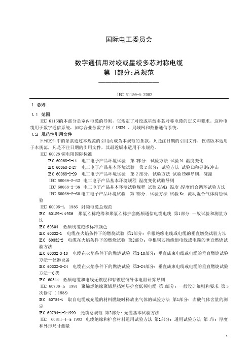
10 9 (ns/km) Vf
(13)
2.1.14 平衡-不平衡变量器 平衡-不平衡变量器(以下简称为“平衡变量器”)是平衡到不平衡的阻抗匹配用的变量器。 2.1.15 相时延 相时延定义为电缆长度 l 除以相速度。相时延由下式确定:
T=
式中: T——相时延(s);
NEXT = 10 lg (P1N P2 N )
4
(dB)
(8)
式中:
P1N — — 主串线对近端的输入功率; P2 N — — 被串线对近端的串音输出功率。
2.1.9 远端串音衰减 输入/输出串音衰减(IO FEXT)定义为:
Байду номын сангаас
IO FEXT = 10 lg (P1N P2 F )
等电平远端串音衰减(EL FEXT)定义为:
(dB)
(9)
EL FEXT = 10 lg ( P 1F P 2F )
式中:
(dB)
(10)
P1N ——主串线对近端的输入功率;
P1F ——主串线对远端的输出功率; P2 F ——被测被串线对远端的串音输出功率。
等电平远端串音衰减(EL FEXT)与输入/输出串音衰减(IO FEXT)相差一个主串线对的衰减。
α = (100 L ) ⋅10 lg (P1 P2 )
式中: α — — 衰减常数,dB/100 m;
(6)
P1 — — 负载阻抗等于信号源阻抗时的输入功率; P2 — — 负载阻抗等于试验样品阻抗时的输出功率;
L — — 试验样品长度,m。
2.1.7 不平衡衰减 不平衡衰减定义为共模功率与差模功率比的对数。
注: 工作区电缆和设备电缆一般要求在一端或两端有合适的连接器。连接器的型式不在本部分中规定。
报关商品编码精品讲义第23讲(59到62章)课堂笔记及课后练习

第59章浸渍、涂布、包覆或层压的纺织物工业用纺织制品一本章的排列结构本章共11个品目排列方式可分为三大部分一是根据涂布材料排列59.01、59.03、59.06、59.07一是具体列名的各种特殊纺织物59.02、59.04、59.05还有一种是工业用纺织制品5908至5911。
二本章的归类要点1、5901是用胶或淀粉物质涂布的主要用于作书籍封面作成的书籍归4901中5901中还提到了描图布而描图纸归4806中符合48章章注八的要求否则归4823中。
做帽里的硬衬布也归5901而作成帽子一般归65章。
5901.9010制成的描图布通常制成一定尺寸的块状适于绷在画架上能归到5901.9010的描图布还没有画上画画上画的归9701。
2、5902这个品目很特别是用高强力纱制成的帘子布可以经过浸渍、涂布、包覆或层压。
而高强力纱本身归5402或5403。
而用橡胶或塑料浸渍、涂布的高强力纱归5604.9000。
5402、5403、5604、5902这几个品目做好比较3、5903是用塑料浸渍、涂布、包覆的纺织物。
塑料与纺织物混合的货品的归类下列情况不归入5903理解掌握1塑料与毡呢、无纺织物混合制成的货品归入5602和5603。
2用塑料浸渍、涂布、包覆或套裹的纺织纱线及54.04或54. 05的扁条及类似品列5604制成织物则列5903 3用塑料浸渍、涂布、包覆或套裹的线、绳、索、缆列5607 4尼龙或其他聚酰胺、聚脂或粘胶纤维高强力纱制的帘子布不论是否用塑料或橡胶浸渍、涂布列5902。
5肉眼可辨出用塑料浸渍、涂布、包覆或层压的纺织物列5903无法用肉眼辨出是否经过塑料浸渍、涂布、包覆或层压的纺织物通常归入第50章至55章、58章或60章6温度在15°C至30°C时用手工将其绕于直径7毫米的圆柱体上会发生断裂的产品列第39章7纺织物完全嵌入塑料内或在其两面均用塑料完全包覆或涂布列第39章8用塑料部分涂布或包覆并由此而形成图案的织物通常列第50章至55章、58章或60章9与纺织物混制而其中纺织物仅起增强作用的泡沫塑料板、片或带列第39章5到9款在本章章注二中已经列名4、5904是具体列名的特殊产品包括了列诺伦和以织物为底布的经涂布或包覆的铺地制品。
