FI-206S
SIMATIC NET 工业以太网交换机 SCALANCE XC-200 操作说明说明书

SIMATIC NET工业以太网交换机SCALANCE XC-200操作说明02/2023法律资讯警告提示系统为了您的人身安全以及避免财产损失,必须注意本手册中的提示。
人身安全的提示用一个警告三角表示,仅与财产损失有关的提示不带警告三角。
警告提示根据危险等级由高到低如下表示。
危险表示如果不采取相应的小心措施,将会导致死亡或者严重的人身伤害。
警告表示如果不采取相应的小心措施,可能导致死亡或者严重的人身伤害。
小心表示如果不采取相应的小心措施,可能导致轻微的人身伤害。
注意表示如果不采取相应的小心措施,可能导致财产损失。
当出现多个危险等级的情况下,每次总是使用最高等级的警告提示。
如果在某个警告提示中带有警告可能导致人身伤害的警告三角,则可能在该警告提示中另外还附带有可能导致财产损失的警告。
合格的专业人员本文件所属的产品/系统只允许由符合各项工作要求的合格人员进行操作。
其操作必须遵照各自附带的文件说明,特别是其中的安全及警告提示。
由于具备相关培训及经验,合格人员可以察觉本产品/系统的风险,并避免可能的危险。
按规定使用 Siemens 产品请注意下列说明:警告Siemens 产品只允许用于目录和相关技术文件中规定的使用情况。
如果要使用其他公司的产品和组件,必须得到 Siemens 推荐和允许。
正确的运输、储存、组装、装配、安装、调试、操作和维护是产品安全、正常运行的前提。
必须保证允许的环境条件。
必须注意相关文件中的提示。
商标所有带有标记符号 ® 的都是 Siemens AG 的注册商标。
本印刷品中的其他符号可能是一些其他商标。
若第三方出于自身目的使用这些商标,将侵害其所有者的权利。
责任免除我们已对印刷品中所述内容与硬件和软件的一致性作过检查。
然而不排除存在偏差的可能性,因此我们不保证印刷品中所述内容与硬件和软件完全一致。
印刷品中的数据都按规定经过检测,必要的修正值包含在下一版本中。
Siemens AGDigital Industries Postfach 48 4890026 NÜRNBERG C79000-G8952-C442-14Ⓟ 02/2023 本公司保留更改的权利Copyright © Siemens AG 2016 - 2023.保留所有权利目录1简介 (7)2安全须知 (15)3安全建议 (17)4设备描述 (25)4.1产品总览 (25)4.2设备视图 (31)4.2.1SCALANCE XC206-2 (ST/BFOC) (31)4.2.2SCALANCE XC206-2 (SC) (32)4.2.3SCALANCE XC206-2G PoE (33)4.2.4SCALANCE XC206-2SFP (34)4.2.5SCALANCE XC208 (35)4.2.6SCALANCE XC208G PoE (36)4.2.7SCALANCE XC216 (37)4.2.8SCALANCE XC216-3G PoE (38)4.2.9SCALANCE XC216-4C (38)4.2.10SCALANCE XC224 (40)4.2.11SCALANCE XC224-4C (41)4.3附件 (41)4.4SELECT/SET 按钮 (47)4.5LED 指示灯 (49)4.5.1总览 (49)4.5.2“RM”LED (50)4.5.3“SB”LED (50)4.5.4“F”LED (50)4.5.5LED“DM1”和“DM2” (51)4.5.6LED“L1”和“L2” (51)4.5.7端口 LED (52)4.6C-PLUG (54)4.6.1C-PLUG 的功能 (54)4.6.2更换 C-PLUG (56)4.7组合端口 (57)4.8以太网供电 (PoE) (58)4.8.1符合标准的电源和电压范围 (58)4.8.2设备的 PoE 属性 (59)4.8.3电源传输和引脚分配 (30 W) (61)SCALANCE XC-200目录4.8.4电源传输和引脚分配 (60 W) (62)4.8.5组态 (62)5组装和拆卸 (63)5.1安装的安全注意事项 (63)5.2关于 SFP 收发器的一般说明 (66)5.3安装类型 (66)5.4在 DIN 导轨上安装 (67)5.4.1基于固定板的凹顶导轨安装 (67)5.4.2无固定板时的凹顶导轨安装 (69)5.5在标准 S7-300 导轨上安装 (70)5.5.1在带有固定板的标准导轨 S7-300 上安装 (70)5.5.2在不带固定板的标准导轨 S7-300 上安装 (71)5.6在标准导轨 S7-1500 上安装 (72)5.6.1在带有固定板的标准导轨 S7-1500 上安装 (72)5.6.2在不带固定板的标准导轨 S7-1500 上安装 (74)5.7基于固定板的墙式安装 (75)5.8更改固定销的位置 (76)5.9拆卸 (77)6连接 (79)6.1不使用 PoE 的设备的安全注意事项 (79)6.2PoE 设备的安全注意事项 (80)6.3有关在危险场所使用的安全注意事项 (82)6.4附加说明 (85)6.5接线规则 (86)6.624 V DC 电源 (87)6.754 V DC 电源 (88)6.8信号触点 (90)6.9功能性接地 (91)6.10串口 (92)6.11工业以太网 (94)6.11.1电气 (94)6.11.2光纤 (95)SCALANCE XC-200目录7维护和清洁 (97)8故障排除 (99)8.1使用 TFTP 下载新固件(无需 WBM 和 CLI) (99)8.2恢复出厂设置 (100)9技术规范 (101)9.1SCALANCE XC206-2 (ST/BFOC) 的技术规范 (101)9.2SCALANCE XC206-2 (SC) 的技术规范 (104)9.3SCALANCE XC206-2G PoE 的技术规范 (107)9.4SCALANCE XC206-2G PoE (54 V) 的技术规范 (110)9.5SCALANCE XC206-2G PoE EEC (54 V) 的技术规范 (113)9.6SCALANCE XC206-2SFP 的技术规范 (116)9.7SCALANCE XC206-2SFP G 的技术规范 (119)9.8SCALANCE XC206-2SFP EEC 的技术规范 (122)9.9SCALANCE XC206-2SFP G EEC 的技术规范 (125)9.10SCALANCE XC208 的技术规范 (128)9.11SCALANCE XC208G 的技术规范 (130)9.12SCALANCE XC208G PoE 的技术规范 (132)9.13SCALANCE XC208G PoE (54 V) 的技术规范 (134)9.14SCALANCE XC208EEC 的技术规范 (136)9.15SCALANCE XC208G EEC 的技术规范 (138)9.16SCALANCE XC216 的技术规范 (140)9.17SCALANCE XC216EEC 的技术规范 (142)9.18SCALANCE XC216-3G PoE 的技术规范 (144)9.19SCALANCE XC216-3G PoE (54 V) 的技术规范 (146)9.20SCALANCE XC216-4C 的技术规范 (150)9.21SCALANCE XC216-4C G 的技术规范 (153)9.22SCALANCE XC216-4C G EEC 的技术规范 (156)9.23SCALANCE XC224 的技术规范 (159)9.24SCALANCE XC224-4C G 的技术规范 (161)9.25SCALANCE XC224-4C G EEC 的技术规范 (164)9.26机械稳定性(运行时) (167)SCALANCE XC-200目录9.27射频辐射符合 NAMUR NE21 标准 (167)9.28电缆长度 (167)9.29交换特性 (168)10尺寸图 (171)11证书和认证 (179)索引 (189)SCALANCE XC-200简介1操作说明的用途这些操作说明适用于 SCALANCE XC-200 系列产品的安装和连接。
PFSWITCH 2048T 商品说明书
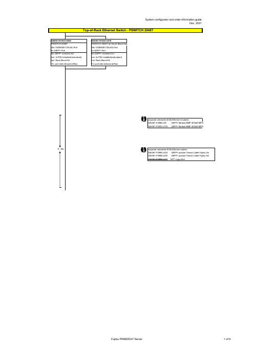
no power cord
T26139-Y3850-E10
T26139-Y1968-L180 T26139-Y1968-L250 T26139-Y1968-L10
T26139-Y1741-L90
T26139-Y1757-L10 T26139-Y1753-L10 T26139-Y1740-L10 T26139-Y1744-L10 T26139-Y1745-L10 T26139-Y1746-L10 T26139-Y1747-L18 T26139-Y1748-L10
Region Kits, 1x per System Region Kit Europe, Contains warranty sheet and safety instructions in German, English, French, Spanish, Italian, Polish, Russian and Welsh language
S26361-F1452-E100 S26361-F1452-E130
End of PSWITCH 2048T
CAT 6A S/STP RJ45 cables can be used for proper cabling: S26361-F3417-L602: CAT 6A, RJ45 connector, 2m S26361-F3417-L603: CAT 6A, RJ45 connector, 3m S26361-F3417-L605: CAT 6A, RJ45 connector, 5m S26361-F3417-L610: CAT 6A, RJ45 connector, 10m S26361-F3417-L615: CAT 6A, RJ45 connector, 15m
QSAN XCubeSAN快速安装手册说明书
感谢您购买QSAN XCubeSAN 存储系统设备。
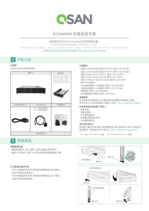
此安装手册将会指引您快速上手并适用于以下型号:XS5224 XS5216 XS5212 XS5226 XS3224 XS3216 XS3212 XS3226 XS1224 XS1216 XS1212 XS1226此手册之其他语言版本可至QSAN 网站下载:https:///m5jzpd打开磁盘托盘的手柄- 打开LFF 磁盘托盘手柄:将托盘手柄按钮由右向左移动; 托盘手柄将会自动弹出。
- 打开SFF 磁盘托盘手柄:将托盘手柄按钮由上往下移动; 托盘手柄将会自动弹出。
XCubeSAN 快速安装手册1 开始之前内容物QSAN XCubeSAN 机型包括:可选配件:- 4端口16Gb/8Gb 光纤信道子卡SFP+(型号:HQ-16F4S2)- 2端口16Gb/8Gb 光纤信道子卡SFP+(型号:HQ-16F2S2)- 4端口10GbE iSCSI 子卡SFP+(型号:HQ-10G4S2)- 2端口10GbE iSCSI 子卡RJ45(型号:HQ-10G2T )- 4端口1GBASE-T iSCSI 子卡RJ45(型号:HQ-01G4T )- BBU+Flash 模块: - 电池备份模块 + 闪存模块(型号:C2F-BM128G ) - 超级电容模块 + 闪存模块(型号:C2F-SP128G )- 滑轨套件(型号:SLR-RM3640)- USB 液晶屏显示模块(型号: LCM-U162)准备安装在安装您的存储系统之前,强烈建议您参照我们的准备工作表。
您可以在以下QSAN 的网页下载此工作表: https:///zk6ucs纪录系统信息在配置工作表上- 系统名称- 管理员密码- NTP 服务器地址- 控制器1的管理IP 地址- DNS 服务器地址其它的信息如下有关其它硬件手册、软件手册或兼容性列表(包括HDD 、SSD 、HBA 和交换机要求),请参阅QSAN 下载中心: https:///download1LFF : Large Form Factor / 3.5” 磁盘 2 SFF : Small Form Factor / 2.5” 磁盘2 安装磁盘解锁磁盘托盘- 磁盘托盘基本上是上锁的,以防止运输过程中损坏。
EXFO光纤测试仪FiberBasix 100系列说明书

C ost-effective, rugged handheld instruments designed for reliable performance E asy-to-use interface for error-free testing I nterchangeable connectors, for fi rst-class fl exibilityP articularly suited to the testing and troubleshooting of LAN/WAN fi ber-optic networksIntroducing EXFO’s FiberBasix testers, a series of handheld instruments designed to meet your basic day-to-day test requirements, while helping you stay within budget. These worry-free, straightforward solutions provide the tools you need to accurately measure signal attenuation during fi ber-optic cable installation.The FiberBasix 100 Series includes two highly convenient instruments: T he ELS-100 Light Source , combines four wavelengths for singlemode and multimode testingT he EPM-100 Power Meter , which offers high accuracy and referencing capabilities2011GLOBAL PORTABLE FIBER OPTIC TEST EQUIPMENT MARKET SHARE LEADERSHIP AWARDELS-100/EPM-100 FiberBasix 100 TestersELS-100 Light Source: Multiwavelength CapabilityEXF O’s ELS-100 Light Source provides excellent stability and high measurement accuracy. Its confi guration includes two singlemode wavelengths (1310 and 1550 nm) and two multimode wavelengths (850 and 1300 nm) for maximum versatility. F or testing all fi ber types. It is the perfect complement to the FiberBasix EPM-100 Power Meter when it comes to measuring attenuation on fi ber-optic links.EPM-100 Power Meter:High Accuracy and Easy ReferencingThe EPM-100 Power Meter provides highly accurate power measurements, as well as reference value setting capabilities. What’s more, this convenient unit requires no offset nulling, and it offers power autonomy of 300 hours, for reliable, long-lasting performance in the field.The EPM-100 Power MeterThe ELS-100 Light SourceELS-100/EPM-100FiberBasix 100 TestersGENERAL SPECIFICATIONSSize (H x W x D) 185 mm x 100 mm x 55 mm (71/4 in x 4 in x 21/8 in)Weight 0.4 kg(0.9 lb)Temperatureoperating –10 °C to 50 °C (14 °F to 122 °F) storage –40 °C to 70 °C(–40 °F to 158 °F)Relative humidity0 % to 95 % non-condensingSTANdARd ACCESSORIESUser guide, Certificate of Calibration, instrument stickers in four languages,AC adapter, EUI-XX (ELS), connector adapter (FOA-XX) (EPM), three AA batteries, wrist strap.SAFETy21 CFR 1040.10 and IEC 60825-1:1993+A1:1997+A2:2001:ELS-500: CLASS 1 LASER PRODUCTELS-100 SPECIFICATIONS a Model b23BL12DCentral wavelength (nm) 1310 ± 20 850 ± 251550 ± 20 1300 +50/—10Spectral width c (nm) ≤ 5 50/135Output power (dBm) ≥ 1/≥ 1 ≥ –20/≥ –20 (62.5/125 µm)Power stability d (dB)8 hours ± 0.10 ± 0.10Battery life (hours) (typical) 50 55Warranty and recommended calibration interval (years)11EPM-100 SPECIFICATIONS a Model eEPM-102Power meter port GePower range f (dBm) 10 to –60Range displayed (dBm)Down to –65Number of calibrated wavelengths g 6Power uncertainty h ±5 % ± 1 nW Resolution (dB)0.01 i Automatic offset nulling Yes Warm-up time f (s) 0Display unitsdB/dBm/W Screen refresh rate (Hz) 3Battery life (hours) (typical) > 300 Warranty and recommended calibration interval (years)1Notesa. Guaranteed unless otherwise specified.b. All specifications valid at 23 °C ± 1 °C, with an FC connector.c.rms for lasers and FWHM for LEDs; typical values for LEDs.d. A fter 15 minutes warm-up; expressed as ± half the difference between the maximum and minimum values measured during the period, with an APC connector on the power meter.e. A ll specifications valid at 1550 nm and 23 °C ± 1 °C, with an FC connector.f. In CW mode, sensitivity defined as 6x rms noise level.g. W avelengths: 850 nmm, 1300 nm, 1310 nm, 1490 nm, 1550 nm and 1625 nm.h.Traceable to national standards.i. From 10 dBm to –50 dBm.ELS-100/EPM-100FiberBasix 100 Testers ORDERING INFORMATIONModelELS-100-12D-23BL = 850/1300 nm LED (62.5/125 mm), 1310/1550 nm laser (9/125 mm) Example: ELS-100-12D-23BL-EI-EUI-89Connector aEI-EUI-89 = UPC/FC narrow key b EI-EUI-90 = UPC/ST bEI-EUI-91 = UPC/SC bEI-EUI-95 = UPC/E-2000 bELS-100-XX-XXModelEPM-102 = Ge detector Example: EPM-102-FOA-22Connector Adapter aFOA-22 = FC (PC/SPC/UPC/APC), NEC-D3 FOA-32 = ST (PC/SPC/UPC)FOA-54 = SCFOA-96B = E-2000FOA-98 = LCEPM-10X-XXNotesa. Other connectors and connector adapters available.Consult our website at /accessories for details.b. Interchangeable connection.TEST KIT ORdERING INFORMATION FBK-103-XX Contractor Test Kit- EPM-102-XX Power Meter, Ge detector- ELS-100-12D-23BL-XX Light Source, 850/1300 nm LED and 1310/1550 nm laser (2 ports)- One TJ-BXX-XX test jumper- One TJ-DXX-XX test jumper- Carrying case GP-10-061EXFO Corporate Headquarters > 400 Godin Avenue, Quebec City (Quebec) G1M 2K2 CANADA | Tel.: +1 418 683-0211 | Fax: +1 418 683-2170 |*************Toll-free: +1 800 663-3936 (USA and Canada) | EXFO America3701 Plano Parkway, Suite 160 Plano, TX 75075 USA Tel.: +1 800 663-3936 Fax: +1 972 836-0164EXFO Asia100 Beach Road, #22-01/03 Shaw Tower SINGAPORE 189702 Tel.: +65 6333 8241 Fax: +65 6333 8242EXFO China36 North, 3rd Ring Road East, Dongcheng District Beijing 100013 P. R. CHINA Tel.: + 86 10 5825 7755 Fax: +86 10 5825 7722 Room 1207, Tower C, Global Trade CenterEXFO Europe Omega Enterprise Park, Electron Way Chandlers Ford, Hampshire S053 4SE ENGLAND Tel.: +44 2380 246810 Fax: +44 2380 246801EXFO NetHawk Elektroniikkatie 2 FI-90590 Oulu, FINLAND Tel.: +358 (0)403 010 300 Fax: +358 (0)8 564 5203EXFO Service Assurance 270 Billerica Road Chelmsford, MA 01824 USA Tel.: +1 978 367-5600 Fax: +1 978 367-5700EXFO is certified ISO 9001 and attests to the quality of these products. This device complies with Part 15 of the FCC Rules. Operation is subject to the following two conditions: (1) this device may not cause harmful interference, and (2) this device must accept any interference received, including interference that may cause undesired operation. EXFO has made every effort to ensure that the information contained in this specification sheet is accurate. However, we accept no responsibility for any errors or omissions, and we reserve the right to modify design, characteristics and products at any time without obligation. Units of measurement in this document conform to SI standards and practices. In addition, all of EXFO’s manufactured products are compliant with the European Union’s WEEE directive. For more information, please visit /recycle. Contact EXFO for prices and availability or to obtain the phone number of your local EXFO distributor.For the most recent version of this spec sheet, please go to the EXFO website at /specsIn case of discrepancy, the Web version takes precedence over any printed literature.SPELS/EPM-100.5AN © 2011 EXFO Electro-Optical Engineering Inc. All rights reserved. Printed in Canada 11/04。
BF6910(BF6911)ASXX规格书
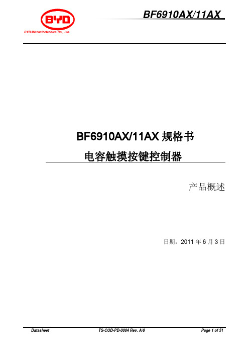
3.1 引脚图 ....................................................................................................................................................... 6 3.2 引脚描述 ................................................................................................................................................... 6
硬件模块单元测试报告-模板

硬件模块单元测试报告编制: 日期:审核: 日期: 批准: 日期:目录目录 (1)第一章概述 (3)1.1目的和范围 (3)1.2测试概述 (3)第二章测试资源及环境 (4)2.1 硬件配置 (4)2.2 测试设备清单 (4)2.3 测试环境 (4)2.4 测试方式 (4)第三章测试数据 (6)3.1 主控板测试 (6)3.1.1短路测试 (6)3.1.2直流电压、纹波测试 (6)3.1.3接口通讯信号测试 (8)3.1.3.1主控板与按键板打印部分 (8)3.1.3.2主控板与核心板 (8)3.1.3.3主控板与液晶屏 (8)3.1.3.4主控板与触摸屏 (9)3.1.3.5主控板与感光板 (10)3.1.3.6主控板对按键板指示灯部分检测信号 (10)3.1.3.8主控板与WIFI板 (10)3.1.4充电测试 (11)3.1.5电源转换效率测试 (11)3.1.5.1 5V电源转换效率测试 (11)2.1.5.2 +8V电源转换效率测试 (13)3.1.6 DC_DC带负载测试 (14)3.2 按键板测试 (15)3.2.1短路测试 (15)3.2.2直流电压、纹波测试 (15)3.2.3接口通讯信号测试 (15)3.2.3.1 按键板与打印机 (15)第一章概述1.1目的和范围本文描述H3硬件模块的测试方法和步骤, 本方案的来源是《H3硬件总体需求》和《H3硬件总体方案》适用范围是:1.2测试概述在硬件模块测试阶段, 测试人员根据细化后的方案进行集成测试, 测试的重点是接口, 主要包括以下几个方面:1.各个板卡接口和测试点电压纹波测试2.控制/检测信号逻辑状态分析第二章测试资源及环境2.1 硬件配置2.3 测试环境环境温度: 0-55℃;大气压力: 700hPa~1060hPa;相对湿度:15% ~ 95%, 非凝2.4 测试方式内部测试第三章测试数据3.1 主控板测试3.1.1短路测试3.1.3接口通讯信号测试3.1.3.1主控板与按键板打印部分3.1.3.2主控板与核心板3.1.3.3主控板与液晶屏3.1.3.4主控板与触摸屏3.1.3.5主控板与感光板3.1.3.8主控板与WIFI板3.1.4充电测试使用电源交流100~240Vac 50Hz/60Hz 使用内置锂电池 12.6V/2600mA3.1.6 DC_DC带负载测试3.2 按键板测试3.2.1短路测试3.2.3接口通讯信号测试3.2.3.1 按键板与打印机。
SF206中文资料
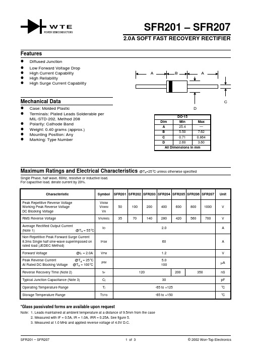
SFR201 – SFR2072.0A SOFT FAST RECOVERY RECTIFIERSingle Phase, half wave, 60Hz, resistive or inductive load.For capacitive load, derate current by 20%.CharacteristicSymbol SFR201SFR202SFR203SFR204SFR205SFR206SFR207UnitPeak Repetitive Reverse Voltage Working Peak Reverse Voltage DC Blocking Voltage V RRM V RWM V R 501002004006008001000V RMS Reverse VoltageV R(RMS)3570140280420560700V Average Rectified Output Current(Note 1) @T A = 55°C I O2.0ANon-Repetitive Peak Forward Surge Current 8.3ms Single half sine-wave superimposed on rated load (JEDEC Method)I FSM 60A Forward Voltage @I F = 2.0A V FM 1.2V Peak Reverse Current @T A = 25°C At Rated DC Blocking Voltage @T A = 100°C I RM 5.0100µA Reverse Recovery Time (Note 2)t rr 120200350nS Typical Junction Capacitance (Note 3)C j 30pF Operating Temperature Range T j -65 to +125°C Storage Temperature RangeT STG-65 to +150°C*Glass passivated forms are available upon requestNote: 1. Leads maintained at ambient temperature at a distance of 9.5mm from the case2. Measured with IF = 0.5A, IR = 1.0A, IRR = 0.25A. See figure 5.3. Measured at 1.0 MHz and applied reverse voltage of4.0V D.C.W T EWER SEMICONDUCTORSI ,P E A K F O R W A R D S U R G E C U R R E N T (A )F S M 0204060110100NUMBER OF CYCLES AT 60Hz Fig.3Peak Forward SurgeCurrent110100110100C ,C A P A C I T A N C E (p F )j V ,REVERSE VOLTAGE (V)Fig.4Typical Junction CapacitanceR00.40.81.21.62.0255075100125150175200I ,A V E R A G E F W D R E C T I F I E D C U R R E N T (A )(A V )T ,AMBIENT TEMPERATURE (C)Fig.1Forward Derating Curve A °50NI (Non-inductive)Ω10NIΩSet time base for 5/10ns/cm+0.5A0A -0.25A-1.0ANotes:1.Rise Time =7.0ns max.Input Impedance =1.0M ,22pF.2.Rise Time =10ns max.Input Impedance =50.ΩΩFig.5Reverse Recovery Time Characteristic and Test Circuit0.010.11.0100.60.8 1.0 1.2 1.4I ,I N S T A N T A N E O U S F W D C U R R E N T (A )F V ,INSTANTANEOUS FORWARD VOLTAGE (V)Fig.2Typical Forward CharacteristicsFORDERING INFORMATIONProduct No.!Package TypeShipping QuantitySFR201-T3DO-154000/Tape & Reel SFR201-TB DO-153000/Tape & Box SFR201DO-151000 Units/Box SFR202-T3DO-154000/Tape & Reel SFR202-TB DO-153000/Tape & Box SFR202DO-151000 Units/Box SFR203-T3DO-154000/Tape & Reel SFR203-TB DO-153000/Tape & Box SFR203DO-151000 Units/Box SFR204-T3DO-154000/Tape & Reel SFR204-TB DO-153000/Tape & Box SFR204DO-151000 Units/Box SFR205-T3DO-154000/Tape & Reel SFR205-TB DO-153000/Tape & Box SFR205DO-151000 Units/Box SFR206-T3DO-154000/Tape & Reel SFR206-TB DO-153000/Tape & Box SFR206DO-151000 Units/Box SFR207-T3DO-154000/Tape & Reel SFR207-TB DO-153000/Tape & Box SFR207DO-151000 Units/BoxProducts listed in bold are WTE Preferred devices.!T3 suffix refers to a 13” reel. TB suffix refers to Ammo Pack.Shipping quantity given is for minimum packing quantity only. For minimum order quantity, please consult the Sales Department.Won-Top Electronics Co., Ltd (WTE) has checked all information carefully and believes it to be correct and accurate. However, WTE cannot assume any responsibility for inaccuracies. Furthermore, this information does not give the purchaser of semiconductor devices any license under patent rights to manufacturer. WTE reserves the right to change any or all information herein without further notice.WARNING : DO NOT USE IN LIFE SUPPORT EQUIPMENT. WTE power semiconductor products are not authorized for use as critical components in life support devices or systems without the express written approval.We power your everyday.Won-Top Electronics Co., Ltd.No. 44 Yu Kang North 3rd Road, Chine Chen Dist., Kaohsiung, Taiwan Phone: 886-7-822-5408 or 886-7-822-5410Fax: 886-7-822-5417Email: sales@Internet: 。
Opone收发器
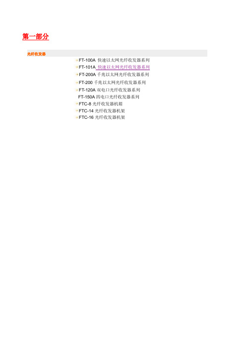
第一部分光纤收发器FT-100A 快速以太网光纤收发器系列FT-101A快速以太网光纤收发器系列FT-200A千兆以太网光纤收发器系列FT-200千兆以太网光纤收发器系列FT-120A双电口光纤收发器系列FT-150A四电口光纤收发器系列FTC-8光纤收发器机箱FTC-14光纤收发器机架FTC-16光纤收发器机架FT-100A 快速以太网光纤收发器系列概述:OpOne FT-100A为10/100Mbps自适应快速以太网光纤收发器(亦称光电介质转换器),可将10Base-T和100Base-TX双绞线电信号同100Base-FX光信号进行相互转换。
使网络的传输距离从铜线100m的极限扩展到120Km(单模全双工方式)。
支持两种不同的网络连接媒体类型:10/100Base-TX和100Base-FX,通过使用交换技术和存储转发技术来实现两种网络连接媒体之间的数据传输。
支持双纤多模、双纤单模和单纤单模多种光纤传输。
特点:自动适应10Mbps和100Mbps环境,便于网络的升级内置高效交换核心,实现流量控制,减少广播包支持全双工和半双工传输模式,能自动协商支持双绞线口自动交叉,方便系统调试安装支持最长1552byte超长数据包传输支持VLAN标签超长数据包传输支持QoS,保证VOIP数据包传输支持STP生成树,构成冗余网络低功耗,低发热,能长时间稳定工作;支持双纤多模、双纤单模和单纤单模多种光纤口选择,扩展了用户的需求。
产品图片:FT-100A(双纤单/多模外置电源) FT-100APS(单纤单模内置电源) FT-100AC(双纤单纤单模块卡)参数规格接入方式10/100Mbps标准IEEE802.3 10Base-T Ethernet,IEEE802.3u,100Base-TX/FX Fast Ethernet, IEEE802.3x Flow control,IEEE802.1q VLAN,IEEE802.1p QoS,IEEE802.1d Spanning Tree波长850nm/1310nm/1550nm传输距离双纤多模:2Km,双纤单模:25/40/60/80/100/120Km,单纤单模:25/40/60/80/100Km五类双绞线:100m端口1个RJ45口:连接STP/UTP五类双绞线1个光纤口:多模—SC或ST(光纤尺寸50、62.5/125μm)订购信息:FT-101A快速以太网光纤收发器系列概述:OpOne FT-101A为10/100M自适应快速以太网光纤收发器(亦称光电介质转换器),可将10Base-T和100Base-TX双绞线电信号同100Base-FX光信号进行相互转换。
业余无线电台无线电发射设备型号核准代码

2015FP2955 2010FP6596 2016FP0113 2015FP1017 2010FP6597 2016FP7171 2017FP1513 2010FP6469 2010FP6468 2017FP1473 2017CP6175 2017FP5599
KENWOOD
TM-481A TK-208 TK-308 TK-378 TK-3207 TK-3307 TM-271A TK-80 TK-868 NXR-710-1 TK-8360 TK-808 TK-8108 TRC-80 TK-380 NX-240 TM-733
LT 灵通
LT-6100Plus LT-9600
PUXING 普星 PX-777 PX-628 PX-2R
QYT KT-8900 KT-7900D KT-8900R
ALINCO
DR-620 DR-435 DX-701
FDC FD-450
Hytera(HYT) 海能达
TC-368S TC-500 TC-585 TC-600 TC-700 TC-780 TM-600 TM-610 PD780G PD980 MD-780 PD500u(1)
MD-780 MD-390 MD-280 TET 6800 DP-290
TG-UV2 TG-K10AT TG-K4AT TG-45AT TG-45UV TG-42AT TG-K2AT(UV) KT-8900R9FJ2078 2004FJ1486 2012FJ6067 2016FJ3275 2016FJ9048 2016FJ6981 2012FJ6027 2013FJ7318 2007FJ3384 2012FJ5854 2012FJ5853 2013FJ9185 2012FJ3483 2013FJ0985 2014FJ2788 2015FJ2550 2012FJ3229 2003FJ1326 99FJ0111 2004FJ1758 2004FJ1486 2004FJ1389 2005FJ0526 2012FJ1337 2016FJ2313 2014FJ4994 99FJ0112 2017FP2540 2014FJ6511 2004FJ2168 2010FP1355
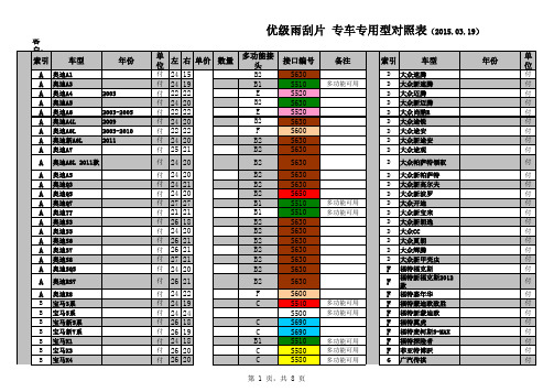
雨刮片专用对照表
多功能可用 多功能可用 多功能可用 多功能可用 多功能可用 多功能可用 多功能可用 多功能可用 多功能可用 多功能可用 多功能可用 多功能可用 多功能可用 多功能可用 多功能可用 多功能可用 多功能可用 多功能可用 多功能可用 多功能可用 多功能可用 多功能可用 多功能可用 多功能可用 多功能可用
170
16
A A A A A A A A A A A A A A A A A A A A A A A A A
T170 T170 T170 T170 T170 T170 T170 T170 T170 T170 T170 T170 T170 T170 T170 T170 T170 T170 T170 T170 T170 T170 T170 T170 T170 S610
优级雨刮片 专车专用型对照表(2015.03.19)
客户: 索引 车型 A 奥迪A1 A 奥迪A3 A 奥迪A4 A 奥迪A5 A 奥迪A6 A 奥迪A4L A 奥迪A6L A 奥迪新A6L A 奥迪A7 A 奥迪A8L 2011款 A 奥迪A5 A 奥迪Q3 A 奥迪Q5 A 奥迪Q7 A 奥迪TT A 奥迪S3 A 奥迪S5 A 奥迪S6 A 奥迪S7 A 奥迪S8 A 奥迪SQ5 A 奥迪RS7 A 奥迪R8
B B B B B B B B B B B B B B B B B B B B B B B B B B B B B B B B B B B B B
宝马2013款X6 宝马118i 宝马120i 宝马318i 宝马M3 宝马M6 奔驰A180 奔驰A200 奔驰B200 奔驰B200 奔驰B200 奔驰C180
920
910
18
910
新天籁 2013款新天籁 2013款新轩逸
Turck MS96流量传感器信号处理器说明书
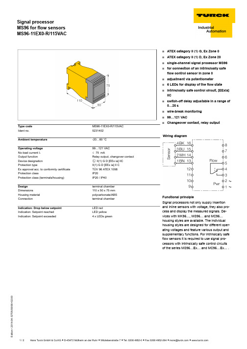
T 05:59:56+02:00Type code MS96-11EX0-R/115VAC Ident no.5231402Ambient temperature-20…60 °COperating voltage 99…121 VAC No-load current I 0ð 75 mAOutput function Relay output, changover contact Device designation É II(1) G D [EEx ia] IIC Protection typeII(1) G D [EEx ia] II C Ex approval acc. to conformity certificate TÜV 96 ATEX 1098Protection classIP20Protection class (terminals/housing)IP20 / IP40Design terminal chamber Dimensions110 x 50 x 75 mm Housing material polycarbonate/ABS Connectionterminal chamber Indication: Drop below setpoint LED red Indication: Setpoint reached LED yellow Indication: Setpoint exceeded4 x LEDs greens ATEX category II (1) G, Ex Zone 0s ATEX category II (1) D, Ex Zone 20s single-channel signal processor MS96sfor connection of an intrinsically safe flow control sensor in zone 0s adjustment via potentiometer s 6 LEDs for display of the flow state sintrinsically safe control circuit, [EExia]IICsswitch-off delay adjustable in a range of 0…25 ss wire-break monitoring s 99…121 VACsChangeover contact, relay outputWiring diagramFunctional principleSignal processors not only supply insertion and inline sensors with voltage, they also pro-cess and display the measured signals. De-vices with MK96…, MS96… and MC96…housing styles are available. The individual housing styles are designed for different oper-ating voltages and feature various output and supplementary functions. For intrinsically safe flow sensors it is required to use signal pro-cessors with intrinsically safe control circuits of the series MS96…Ex… and MC96…Ex… .T 05:59:56+02:00Operating manual Intended useThis device fulfils the directive 94/9/EC and is suited for use in explosion hazardous areas according to EN50014 and EN50020.In order to ensure correct operation to the intended purpose it is required to observe the national regulations and directives.For use in explosion hazardous areas conform to classificationII 1 G and II 1 D (Group II, Category 1 G, electrical equipment for gaseous atmospheres and category 1 D, electrical equipment for dust atmo-spheres).Marking (see device or technical data sheet)Ex II 1 G and Ex ia IIC T6 acc. to EN60079-11 and -26 and Ex II 1 D Ex iaD 20 T95°C acc. to EN60079-11 and EN61241-0 and -11Local admissible ambient temperature -20…+60 °CInstallation / CommissioningThese devices may only be installed, connected and operated by trained and qualified staff. Qualified staff must have knowledge of protection classes, directives and regulations concerning electrical equipment designed for use in explosion hazardous areas.Please verify that the classification and the marking on the device comply with the actual application conditions.This device is accessory equipment which features intrinsically safe circuits as well as non-intrinsically safe circuits. It may only be installed out-side the explosion hazardous area in dry, clean and well monitored areas. If a declaration of conformity or declaration of the manufacturer as a category 3 device exists, the device may be installed in zone 2. Special conditions for safe operation must be observed. Intrinsically-safe elec-trical equipment can be connected to the intrinsically-safe connections. All equipment must comply with the demands for operation in the exist-ing zone of the explosion hazardous area. If the intrinsically safe circuits lead to the dust explosion hazardous zones 20 or 21, it is important to ensure that the devices connected to this circuit fulfil the demands for category 1D or 2D and are certified accordingly. If the equipment is inter-connected, it is necessary to perform the "Proof of intrinsic safety" (EN 60079-14). Equipment which has been used once to connect intrinsical-ly safe circuits to non-intrinsically safe circuits is no longer suitable for subsequent use with intrinsically safe circuits. Relevant regulations ex-ist for the establishment of intrinsically-safe circuits, mounting of external connection parts as well as the characteristics and laying of cables.Cables and terminals with intrinsically-safe circuits must be marked. They should be separated from non-intrinsically safe circuits or must fea-ture appropriate insulation (EN 60079-14). Observe the prescribed clearances to earthed components and connections of other devices to the intrinsically-safe connections of this device. Unless expressed specifically in the device-specific operating instructions, the approval becomes void if the device is opened, repaired or actions are performed on the device by someone other than approved experts or the manufacturer. Vis-ible changes to the device housing, such as brown-black discolourations caused by heat, as well as holes or bulges also indicate a serious dan-ger. Switch off the device immediately. With the associated electrical equipment the interconnected intrinsically-safe equipment must also be checked. Inspection of a device with regard to the explosion protection can only be performed by an expert or the manufacturer. The operation of the devices is only permitted in conjunction with the permitted data printed on the side of the housing. Before any commissioning or modifica-tion of the device interconnections, ensure that the respective regulations, directives and conditions have been complied with and also ensure that use is only for the intended purpose and the safety requirements have been fulfilled.Installation and mounting instructionsAvoid static charging of cables and plastic devices. Please only clean the device with a damp cloth. Do not install the device in a dust flow and avoid build-up of dust deposits on the device.If the devices and the cable could be subject to mechanical damage, they must be protected accordingly. They must also be shielded against strong electro-magnetic fields.The pin configuration and the electrical specifications can be taken from the device marking or the technical data sheet.In order to avoid contamination of the device, please remove possible blanking plugs of the cable glands or connectors only shortly before in-serting the cable or opening the cable socket.Special conditions for safe operationThe device must be protected against any kind of mechanical damage.service / maintenanceRepairs are not possible. The approval expires if the device is repaired or modified by a person other than the manufacturer. The most important data from the approval are listed.。
ADRV9026四通道宽带RF接收器平台商品介绍说明书

VISIT ADRV9026Quad-Channel, Wideband RF Transceiver Platform200 MHz Bandwidth Integrated Radio Transceiver SolutionApplications►Macro base stations ►Massive MIMO►Small cell designs1See page 3 for future enhancements in the ADRV902x family roadmapSmallest Size, Lowest Power Transceiver Solution for Base Transceiver Stations (BTS )►Smallest size reduces footprint and enhances form factor flexibility►50% power consumption reduction over previous generation ADRV9009 for increased radio density►Enables ORAN small cell designs with lowest system power and costHighly Integrated, High Performance Software-Defined Radio►2× integration over ADRV9009►Supports up to 200 MHz bandwidth and covers all bands from 650 MHz to 6 GHz 1Common Platform Design for 3G/4G/5G Reduces Complexity, Development Costs, and Time to Market►Single-chip FDD/TDD solution simplifies hardware and software development ►Common API across multiple applications►Reduces product development cycles for band and power variants►Enables modular architecture for scalable radio solutionsADRV9026 Quad-Channel, Wideband RF Transceiver Platform RF SynthRF Synth ORX1/ORX2TX 1TX 2RX10°90°RX2RX3+RX3–RX4+RX4–RX1+RX1–RX2+RX2–TX3+TX3–TX4+TX4–TX1+TX1–TX2+TX2–ORX3+ORX3–ORX4+ORX4–ORX2+ORX2–ORX1+RF SynthLO 1LO 2GPIO AuxADC AuxDACGPINT1JESD204B/C Serial InterfaceClock GenerationandSynchronizationDEVCLK±SYSREF±LO 2LO 1LO 2LO 1RX3, RX4, TX3, TX4, ORX 3/ORX4RX1, RX2, TX1, TX2, ORX 1/ORX2pFIR,LO Leakage,QEC, Tuning,InterpolationGPIO_ANA_n AUXADC_nSPI_CLKSPI_EN SPI_DO SPI_DIORXn_EN TXn_EN ORXn_EN VDDA_1P8VDDA_1P3VDDA_1P0VDIG_1P0EXT_LO1±EXT_LO2±PWR MGMTGPINT2RESET TESTSERDOUTA±SYNCIN1±SYNCIN2±SYNCIN3±SERDINA±SERDINB±SERDINC±SERDIND±LO 3LO 3SYNCOUT1±SYNCOUT2±8419VIF444SERDOUTB±SERDOUTC±SERDOUTD±MicroprocessorADCADCDACDACADCADCDecimation,pFIR,DC Offset,QEC,Tuning,OverloadDecimation,pFIR, AGC,DC Offset,QECTuning RSSI,OverloadControl InterfaceSPI Port0°90°0°90°2ADRV9026 Quad-Channel, Wideband RF Transceiver Platform3Visit ADRV9026 Overview►Four differential transmitters ►Four differential receivers►Two observation receivers with two inputs each ►Center frequency: 650 MHz to 6000 MHz ►Maximum receiver bandwidth: 200 MHz ►Maximum transmitter bandwidth: 200 MHz►Maximum transmitter synthesis bandwidth: 450 MHz►Maximum observation receiver bandwidth: 450 MHz►Fully integrated independent fractional-N radio frequency synthesizers ►Fully integrated clock synthesizer►Multichip phase synchronization for all local oscillators and baseband clocks ►Support of TDD/FDD 3G/4G/5G applications►16 Gbps JESD204B/C digital interfaceSee roadmap below for future enhancementsADRV9026 Family RoadmapEnhanced features and functions will be added to the ADRV9026 over time, including:►25 Gbps SERDES support►Extending LO frequency range down to 75 MHz►Support for an external LO►Filter Wizard to generate custom profilesAn enhanced version from the ADRV902x family will be released in 2020 with integrated DPD and CFR, reducing FPGA requirements, as well as lowering total system power and cost.RadioVerse Ecosystem and PartnershipsRadioVerse ® is a design and technology ecosystem for advanced radio design and development. We offer market-leading integrated transceiver technology, software tools, evaluation and prototyping platforms, a range of reference designs, and radio solutions. RadioVerse is building up a global partnership network to provide customers all levels of design support. ADRV9026’s partner network and reference design ecosystem will be launched on /radioverse in 2020.Evaluation SystemThe evaluation system comprises an FPGA carrier board ADS9-V2EBZ and a radio daughtercard, coming with two frequency bands of matching: –HB for 2.8 GHz to 6 GHz and –MB for 650 MHz to 2.8 GHz. Compatible evaluation software is provided for download, including API library, Windows GUI, and a binary image for FPGA configuration.Radio CardsCarrier BoardsSoftware and DriverE v a l u a t i o n S y s t e m►ADRV902X-HB/PCBZ (for 2.8 GHz to 6 GHz )►ADRV902X-MB/PCBZ (for 650 MHz to 2.8 GHz )►ADS9-V2EBZ(FPGA motherboard with Xilinx ® UltraScale+™)►Operating system-agnostic API source in ANSI C►Windows GUI for transceiver configuration and data capture►Binary image for FPGA configurationFor regional headquarters, sales, and distributors orto contact customer service and technical support, visit /contact.Ask our ADI technology experts tough questions, browse FAQs, or join a conversation at the EngineerZone Online Support Community. Visit .©2019 Analog Devices, Inc. All rights reserved. Trademarks and registered trademarks are the property of their respective owners.PH21775-11/19(A)VISIT 。
SDH传输设备

•学习目标通过对本文档的学习,你将掌握以下内容:•各种连接设备介绍•各厂家SDH传输设备的介绍•学习内容♦各种连接设备(OBB、ODF和DDF)•各厂家SDH传输设备LUCENTrDACSVI.SLM-I6.ISM-2000(ISM-bISM-4)FJT:FLX2500A.FLX600A.FLX150/600OBB(光缆分纤盒):光缆从光分纤盒一端进入,在分纤盒内部通过熔接器与尾纤固定相连.尾纤通过ODF与传输设备相连.在光设备中,两根光纤组成一个收发,但是端口算做两个.这与电设备不同.ODF(光数字配线架):如图示,ODF分为纤面和缆面.ODF缆面:将光缆中的光纤从OBB中引出后,与ODF相连的一面.ODF纤面:0DF缆面的对面,用于连接传输设备.DDF(数字配线架):DDF下端:用于跳线和客户设备连接■■■.] DDF上端:用于设备连接一关联规则:指设备与DDF下端连接时所遵循的•些规则,常用的关联规则包括:上下关联和左右关联■■■■I上下关联:指将相隔为一定数目的不同面板上的对应端子作为一对收发端子左右关联:指将同一面板中相隔为一定数目的不同端子作为一对收发端子跳线:指DDF/ODF的不同端口之间按照一定规则的物理连接二、SDH传输设备1.SDH传输设备概述:(I)SDH的优点:•复用和解复用技术简单•低阶信号可直接复用成高阶信号,无需中间复用过程•增强了操作、管理和维护能力•随传输技术的发展可方便地提高信号传输速率•各厂家的设备在网络上可以互通(2)SDH传输设备:SDH传输设备包括:终端复用器、分插复用器、再生器和DXC.终端复用器的主要任务是将低速支路信号和155Mb∕s电信号纳入STMT帧结构,并经电/光转换变换为STMT光线路信号;其逆过程正好相反.而分插复用器是•种新型的网元,它将同步复用和数字交叉连接功能综合于一体,具有灵活地分插任意支路信号的能力,在网络设计上有很大灵活性.DXC是一种具有1个或多个准同步数字体系(G.702)或同步数字体系(G.707)信号端口,并至少可以对任何端口信号速率(和/或其子速率信号)与其它端口信号速率(和/或其子速率信号)间进行可控连接和再连接的设备.2.LUCENT产品介绍・DACSVI定义:DACSVI是一种用于对PDH或SDH数字信号进行交叉连接的系统,TU-12等级的4/1交叉连接设备,特别适于对含有VC-12净负荷的STM-I信号进行分导(Grooming),内部具有网元管理功能.功能:(1)替代复用器:DACSVI提供的复用功能可以替代低阶的外部复用器和外部光路系统.无需中间的复用设备就可以方便地在高阶信号中分插低阶支路的VC-12信号.63个2Mb∕s◄ ---------------------------- ►1个140Mb∕s或STM-I16个2Mb∕s◄ ---------------------------- ►1个34Mb∕s4个34Mb/s ◄ ---------------------------- ►1个140Mb∕s或STM-I1个140Mb/s ◄ ---------------------------- ►1个STM-IDACSVI具有下列复用功能:(2)替代人工交叉连接:DACSVI用软件控制交叉连接矩阵,操作人员可以在远端增加或删除交叉连接,而且DACSVl所占空间比人工交叉连接架少(3)集中的网络监控:可以从远端对DACSVl进行操作、管理、维护与设置(4)PDH与SDH的网关:由于DACSVI同时具有PDH和SDH的接口,可以连接这两种数字体系,支持现有PDH业务,用户信息可自由和透明地穿过PDH与SDH网络的边界,有利于电信系统由当前的PDH网络逐步向完全的SDH网络过渡(5)设备替换:利用DACSVI的滚动和桥接命令用户可以在影响业务最小的情况下替换设备(6)枢纽:网络中的某些节点可作为枢纽,以减少节点间的点对点连接(7)信号分导:对于枢纽型的网络,DACSVI是有效利用带宽的极佳工具.来自不同方向而向同一方向传送的VC-12业务.可以由DACSVI加到具有足够空闲容量而又是传到同一地点的某一STM-I中去.这种技术叫分导.它可以充分利用空余容量特性:(1)具有SDH与PDH信号端口,同步宽带交叉连接(2)在SDH与PDH接口间用软件实现VC12的交叉连接(3)交叉连接在VC12等级:在交换前,系统把2Mb∕s信号映射到VC12;对于高阶信号,系统把它们解复用并映射到VC12(所有进入DACSVI的信号,如果经过PDH设备进入的,则必须是P12(2Mb∕s)组成的结构信号;如果经过SDH设备进入,必须是VC12结构的.(4)P31信号必须由P12信号复用而成(5)P41信号必须由P31信号复用而成(6)STM-I信号必须是由VC12复用而成传输接口:(l)2Mb/s:DACSVI通过TPU2接口机盘提供2Mb∕s端口(2)34Mb/s:DACSVI通过TPU34TMX提供34Mb/s信号的传输与复用接口⑶140Mb/s:DACSVI通过TPUI40TMX提供140Mb∕s信号的传输与复用接口(4)STM-1电口(局内):DACSVl通过LPUl55/E提供STM-I电信号的传输接口⑸STM-I光口(短距离):DACSVl通过LPUI55/0提供STM-I光信号的传输接口系统硬件组成:分六层描述DACSVI 物理结构示意图端口架:端口架用于提供一系列线路或支路传输端口.端口架又称输入输出架,可由LPUl 线路子架、TPU2.TPU34/140支路子架组成.由于系统交叉连接容量的限制.端口架最多可以有12个,最多可以安装24个端口子架.LPUl 子架DACSVl 通过LPUI55提供STM-I 信号的传输接口(光或电)LPUl 子架包括: (1)两个插机盘的的子框(2)一个正面连接的连接面板(3)子架正面有三块架门LPUl 子架是固定PortIoierface ComplexMaioCoolToUcrComplexCrossConnectComplexCross-CoooectComplexPortInterface Complex每块LPU155需配备1块OPPU,最多可安装8块LPU155单元架每块TPU2机盘支持8个2.048Mb∕s双向信号,每个TPU2子框最多可安装8块工作机盘和1块保护机盘.每个子框只要有业务就必须配备一块OBTU,也可另配一块作为保护.每块OBTU 单元最多可把63个2Mb∕s信号复用成一个STM-I信号,然后通过内部光缆连接到CC子架的OTU 单元.・SLM-16定义:同步线路复用设备SLM-16可以将16个140Mb∕s或者155Mb/s的支路信号复用成一个STM-16的同步信号(即一个Z5Gb∕s的信号)在光纤上进行传输或者将STM-16信号解复用还原成PDH或SDH所能接受的信号.功能:(1)端机在一条综合线路上提供复用及线路终端,低速率的支路信号可以是140Mb/s的PDH 信号,也可以是155Mb/s的同步信号(2)上、下电路复用器把较低速率的支路信号向(或自)高速率信号流中插入(或引出)(3)再生器(即中继器)把已经衰减了的光信号恢复到原先的光脉冲波形(4)配有在本地和远端进行维护、控制和网络管理的设备(5)终端机型,为光接口提供1+1保护(6)还可为电口支路信号提供1:N的保护根据配置不同,它可用作终端系统.上下电路系统和再生(中继)系统:终端系统配置中线路信号等于支路信号之和,再生系统配置中一定插有RGU机盘,上下电路系统中一定插有SWR和STVT机盘,并且有LNC、CTL和MEM机盘对上下电路实行控制.内部连接板(ICP) UPLn*4饺岫⅛π依LPSF 2:PSF1:PSF2:PSF3:PSF4:PSF 1+1终端机枢内郎连接板(ICP),UPL1:PSF2:PSF中继机框1 :PSF2 :PSF3:PSF4: PSF上、下电路机枢如图示,用作上下电路系统时,一般通过DDF架与ISM-I相连图示配置是上下电路系统配置,采用的是2纤双向复用段保护环.可以从一个2.5Gb∕s的信号下16个155Mb∕s的信号,TPU(P)是用作1:8的盘保护. CONNECTINGPANELDDF LMEM系统存储单元,与CTL、LNC•起完成上下电路配置的控制功能LNC线路控制器单元,与MEM、CTL一起完成上下电路配置的控制功能电源单元PSF电源滤波器单元,PSF对输入电源滤波后通过底板分配到各单元盘操作接口单元UPL用户维护面板•ISM-2000定义:智能同步复用器ISM-2000可以将PDH信号和SDH信号复用进155Mb∕s的STMT(ISMT)或622Mb∕s的STM-4传输线上(ISM-4)或者将STM-4或STM-I信号解复用还原成PDH或SDH所能接受的信号机框描述:图为机框布局示意图,机框内提供:2个槽道用于 ------- 线路端口单元(LPU)2个槽道用于 ------- 指针处理和交叉连接单元(PPe)8个槽道用于 ------- 支路端口单元(TPU)1个槽道用于 ------- 保护支路端口单元(TPU)2个槽道用于 -------- 定时产生器单元(TGU) 1个槽道用于 -------- 系统控制器(CTL) 1个槽道用于 -------- 数据分组交换(DPS) 2个槽道用于 -------- 电源滤波器(PSF) 1个槽道用于 -------- 用户维护面板(UPL)根据配置不同,它可用作终端系统.上下电路系统和再生(中继)系统终端机框配置在这种配置下,系统可以将VC12终结或适配至IJSTM 线路中。
NXP mcu
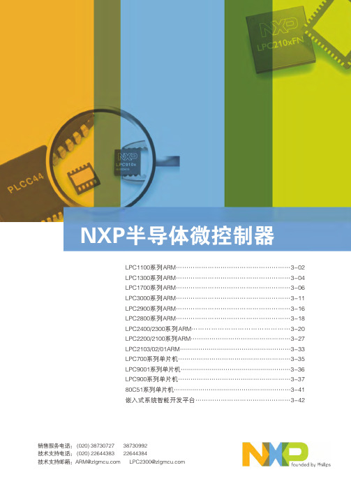
TinyM0核心板电路为LPC111x芯片的最小系统,硬件支持2.54mm间距的 标准排针。用户可以将TinyM0核心板配套自行设计的底板进行产品开发。 ● 支持多款芯片
和16位竞争产品的2至4倍。
Cortex-M0内核
● 32位ARM RISC处理器,16位Thumb指令集; ● 功耗与面积高度优化,设计专用于低成本、低功耗场合; ● 24位SysTick定时器; ● 32位硬件乘法器; ● 中断现场自动保存,有处理决定性、固定延迟的中断能力; ● 系统接口支持小端或字节不变的大端数据访问; ● SWD串行线调试。
LPC1300选型表:
器件型号 LPC1343 LPC1342 LPC1313 LPC1311
Flash (KB) 32 16 32 8
SRAM(KB) 8 4 8 2
USB 2.0 Device Device
-
I2C(Fast+) 1 1 1 1
ADC 8ch/10bit 8ch/10bit 8ch/10bit 8ch/10bit
置的新型开漏工作模式
LPC1100
◎ 四个通用计数器/计数器 ◎ 可编程的看门狗定时器(WDT),带锁死功能 ◎ 系统计时器 ◎ 各外设自带时钟分频器,有利于降低功耗
芯片特色:
Cortex-M0处理器性能 ● Cortex-M0微控制器可以轻松超越高端8位和16位器件的
性能水平; ● 内核额定性能为0.9DMIPS/MHz,相当于与其最接近的8位
SPVA 24 7操作多功能显示器说明书

SPVA1920 x 1080DVI-DMini D-sub 15 pin5 BNC (RGB/HV)DisplayPortComposite (BNC)S-VideoHDMIBNCStereo Mini JackRS-232C in/out for multiple monitor control, Ethernet, IR, DDC/CI15W Stereo / 8Ω10W Stereo / 8Ω41-104°F / 5-40°C20-80%55”4000:147.6 x 26.8 in. /1209.6 x 680.4 mm4.6 A@100-120V1.85 A@220-240V255W<0.5W0.73 in. / 0.73 in.,18.5 mm / 18.5 mm49.2 x 28.4 x 4.9 in. /1250.2 x 721 x 125.4 mm60.2 x 37.1 x 12.2 in.1530 x 942 x 311 mm88.2 lbs. / 40 kg111.3 lbs. / 50.5 kg400 x 400 mm (4 holes)46”0.530 mm3500:140.1 x 22.5 in. /1018.1 x 572.7 mm3.6 A@100V1.5 A@240V155W0.6 in. / 0.6 in.,16.5 mm / 16.5 mm41.6 x 24 x 4.1 in. /1055.4 x 608.6 x 103 mm47.6 x 30.8 x 10.3 in. /1210 x 782 x 261 mm52.5 lbs. / 23.8 kg67.9 lbs. / 30.8 kg40”0.461 mm3000:134.9 x 19.6 in. /885.6 x 498.2 mm3.5 A@100V1.45 A@240V145W0.6 in. / 0.6 in.,15.5 mm / 15.5 mm36.2 x 21 x 4.1 in. /919.7 x 532.2 x 103 mm42 x 26.9 x 10.3 in. /1066 x 682 x 261 mm45.9 lbs. / 20.8 kg59.1 lbs. / 26.8 kgViewable Size (Diagonal)Panel TechnologyNative ResolutionPixel PitchBrightness (Typical/Maximum)Contrast Ratio (Typical)Active Screen Area (W x H)Input TerminalsOutput TerminalsExternal ControlSpeaker OutputAdditional FeaturesPower RequirementsPower Consumption (Typical)Power Consumption (Standby Mode)Bezel Width (L/R, T/B)Dimensions (without stand; WxHxD)Packaging Dimensions (WxHxD)Net Weight (without stand)Gross Weight (with box)VESA Hole ConfigurationOperating TemperatureOperating HumidityIncludedOptionalRGB1 (Digital)RGB2 (Analog)RGB3 (Analog)RGB4 (Digital)Video 1Video 2Video 3Component Video 1 (DVD/HD)AudioRGB (Analog)RGB (Digital)VideoAudioExternal Speaker JackInternal SpeakerLCD MODULECONNECTIVITYFEATURESPOWERPHYSICAL SPECIFICATIONSENVIRONMENTAL CONDITIONSACCESSORIES70”0.807 mm420 cd/m² / 600 cd/m²2000:161.0 x 34.3 in. /1549.4 x 871.6 mm8.2 A@100-120V3.3 A@220-240V545W2.5 in. / 2.5 in.,62.4 mm / 63.4 mm66.1 x 39.5 x 7.8 in. /1680 x 1004 x 198 mm76.8 x 49.6 x 18.1 in. /1950 x 1260 x 460 mm208.3 lbs. / 94.5 kg251.3 lbs. / 114 kgAdvanced thermal capabilities, Sealed professional panel, Expansion slot, Ethernet control and Communication, CableComp+, TileMatrix (10x10),TileComp, Programmable lookup tables, Plug and Play (DDC/CI, DDC2B), PIP (remote), POP, 6-axis colour adjustment, Multi-level programmable zoom,Scheduler (w/ RTC), Sharpness/softness, Off-timer (countdown), Screen saver, Vacation switch, 10-bit gamma,AutoBright (signal input), Windows Vista-certified IR, Portrait-capable,Metal rear cabinet, Handles, Touch- and protective screen-ready, Ambient light sensor,Carbon footprint meter, Colour temperature adjustment (2600-10,000K)Stand (ST-4020),Speakers (SP-P4046PV),DVI Daisy Chain Board (SB-L008WU),SBC (NET-SBC-01/NET-SBC-02),Media Player Board (SB-L008KU),HD-SDI Board (SB-L007KK),Slot Adapter (SB-02AM),SBC (N8000-8830 / N8000-8822) *3Stand (ST-4620),Speakers (SP-P4046PV),Speakers (SP-RM1),DVI Daisy Chain Board (SB-L008WU),SBC (NET-SBC-01/NET-SBC-02),Media Player Board (SB-L008KU),HD-SDI Board (SB-L007KK),Slot Adapter (SB-02AM),SBC (N8000-8830 / N8000-8822) *3Power cord, Mini D-sub 15 pin cable, Wireless remote control, Batteries, Cable cover,Setup manual, Clamps, Screws, CD-ROM (user manual), Thumbscrew for optional stand (*1), Eyebolt (*2)300 x 300 mm (4 holes)0.630 mm500 cd/m² / 700 cd/m²500 cd/m² / 650 cd/m²<0.5WStand (ST-701), Speakers (SP-RM1),DVI Daisy Chain Board (SB-L008WU),SBC (NET-SBC-01/NET-SBC-02),Media Player Board (SB-L008KU),HD-SDI Board (SB-L007KK),Slot Adapter (SB-02AM),SBC (N8000-8830 / N8000-8822) *3Stand (ST-5220), Speakers (SP-RM1),DVI Daisy Chain Board (SB-L008WU),SBC (NET-SBC-01/NET-SBC-02),Media Player Board (SB-L008KU),HD-SDI Board (SB-L007KK),Slot Adapter (SB-02AM),SBC (N8000-8830 / N8000-8822) *3/ap/Large-Screen LCDDimensionsProfessional Series LCD Public Displays P702: 1680P702: 198P702: 60.5P72:14P72:877.2P402: 888.7P462: 1022.4P552: 1213.2P402: 919.7P462: 1055.4P552: 1250.2P402: 103P462: 103P552: 125.4P42:51.2P462:575.6P552:684P42:532.2P462:68.6P552:721P702: 1555.2All hardware and software names are brand namesand/or registered trademarks of the respective manufacturers.All rights reserved.All specifications are subject to change without notice.Feb 2012WLCD-1202-083D(mm)*1 : Excludes P702 *2 : Only for P702 *3:SB-02AM requiredSharing with 5 BNC (RGB/HV)Audio 1 & 2 (Stereo Mini Jack), Audio 3 Stereo (RCA), HDMINoDVI-D ( DVI-D IN, HDMI IN), DisplayPort ( DisplayPort IN)Stable and reliable 24/7 operation in full HDThe professional-grade construction of P Series panels contributes to 24/7 usage, an overalllonger panel life, lower likelihood of the Mura effect from localized heat, virtually no imageretention and the ability to use in landscape or portrait orientation. Thermal protection of thepanels starts with an extra thermal layer on the display panels to diffuse heat, followed bymulti-fan-based technology specially designed to work in both landscape and portrait modesand be controlled locally or remotely. Internal temperature sensors control self-protective circuits,while special self-diagnostics communicate the status of the thermal characteristics.The screen is equipped with an advanced slim bezel that has beenreduced to 15.5 mm. The bezel* is so slim and inconspicuous that itblends in well with the installation environment while highlighting thepicture.The discreet, slim bezel enables the stunningfull HD images to become the focus of the display*On the P402. The P552 and P462 have bezels of 18.5 mm and 16.5 mm, respectively.A built-in expansion slot for flexible functionality and installationFlexible installation opportunitiesThe expansion slot enables you to integrate an internal board, whichprovides greater flexibility to install displays in locations without space fordisplay devices like computers and display controllers. With a conversionadapter(SB-02AM: option), you can also use OPS*-compliant SBC.Expansion slot for enhanced functionalityThis series comes with an expansion slot, enabling you to expand or addfunctions to the display. You can integrate an internal board at any time,future proofing your investment.*OPS is a standard set up by Intel Corporation.*SB-02AM requiredW i th thi s fe atu re the b r i g htne s s leve l i s adju s te dautomatically, ensuring perfect brightness at all timesavoiding uncomfortable brightness levels and reducingunnecessary power consumption. The ambient light sensorcan be programmed by the user to perfectly adjust thesensor performance to the users needs.Ambient light mode adjusts the panel brightnessautomatically to match ambient light conditionsHigh reliability and user-friendly control function for professional useRS-232C enables multi-display control and daisy chain, allowingfor individual and group-addressable control, and simple,effective setup and monitoring of the display.Ethernet connectivity adds the same RS-232C control plusautomatic email notification for diagnostic purposes.SNMP function allows users to control and monitor items suchas power, brightness and screen mode via network.NaViSet™ software offers an intuitive graphical interface,allowing easy adjustment of display settings via mouse andkeyboard operations. NaViSet Administrator provides all theadvanced control to remotely located IT professionals.DDC/CI standard allows PC control of the display based on theVESA command set.HDMI connector Thinner and lighter (excludes P702)Board SBC (Single Board Controller)Media Player BoardSlot Adapter HD-SDI BoardNET-SBC-01 (with OS)NET-SBC-02 (without OS)N8000-8830/N8000-8822SB-L008KUSB-02AM SB-L007KKThe P Series boasts the industry’ s most extensive control, diagnostics and communication features, providing the highest level of remote display management.。
AFL FlexScan PON OTDR用户手册说明书

Performance-packed: With SmartAuto multi-pulse acquisition, up to 37 dB dynamic range and best-in-class 20 m PON dead zone, FlexScan PON OTDRs test FTTH PONs up to 1:64 while still detecting and measuring events only meters apart.Fast! FleXpress mode completes dual-wavelength tests in <5 seconds – 10 x faster than conventional OTDRs! For multi-fiber testing, FleXpress mode automatically controls 12-fiber MPO Switch to further reduce multi-fiber test time.User-friendly: FlexScan OTDRs enable both novice and expert technicians to quickly, reliably and accurately detect, locate, identify and measure optical network components and faults. After applying industry-standard or user-set pass/fail criteria, the network is displayed using FlexScan’s intuitive, icon-based LinkMap view. Acquired results may be stored internally or externally. FlexScan automates test setup, shortens test time and simplifies results interpretation, improving efficiency and reducing the cost of test.Pocket-sized: At 3.5 x 6 x 1.75 in. (86 x 160 x 43 mm) and less than one pound (0.4 kg), FlexScan OTDRs truly fit in your pocket, yet still provide a large, bright indoor/outdoor touchscreen display and all-day operation.And Affordable: With optional connector inspection, integrated source, power meter and VFL, FlexScan offers an all-in one solution, ensuring technicians have everything they need to locate and resolve optical network issues. Uploaded results may be viewed and reports may be generated using the included Windows-compatible TRM ® 2.0 Test Results Manager software.Available in Convenient, Cost-saving Installation and Troubleshooting Kits cable, FOCIS Flex connector inspection probe and tips, and/or AFL’s universal optical fiber identifier (OFI).Features• • • • • • • • • • • •Applications• • • •FleXpress ™Fast OTDR TestWith Wave ID, the power meter automatically synchronizes to a single or multi-wavelength Wave ID optical signal sent by an AFL light source. The power meter automatically identifies received wavelengths and measures power and loss at each wavelength, saving significant test time and eliminating setup errors.The VFL’s eye-safe red laser enables users to visually pinpoint the location of macro-bends and fiber breaks often found in splice closures and fiber cabinets.FlexScan ® OTDR with SmartAuto ®, FleXpress ™ and LinkMap ®MODEL: FS200-#-50-60-100-300-304OTDREmitter Type LaserSafety Class b Class IFiber TypeSingle-modeWavelengths (nm)155016501310/15501310/15501310/1550/1650Center λ Tolerance ±20 nm (CW mode)Dynamic Range (dB) c283732/3037/3637/36/37Event Dead Zone d (m) 1.00.80.80.80.8Atten. Dead Zone e(m) 6.0 3.5 3.6 3.5 3.5PON Dead Zone f (m)N/A 30N/A 2020Pulse Widths 3, 5, 10, 20, 30, 50, 100, 200, 300, 500 ns;1, 2, 3, 10, 20 µsRange Settings 250 m to 240 km Data Points Up to 300,000 (Expert mode .SOR file)Data Spacing 5 cm to 16 m Group Index of Refraction 1.3000 to 1.7000Distance Uncertainty (m)±(1 + 0.003% x distance + data point spacing)Linearity (dB/dB)±0.05Trace File Format Telcordia SR-4731 Issue 2Trace File Storage Medium4 GB internal memory (>1000 traces); External USB memory stickData Transfer to PC USB cable or Bluetooth ® or WiFi (option)Standard OTDR Modes SmartAuto, Expert, Real TimeDisplay Modes LinkMap Summary, LinkMap Events, Trace FleXpress Fast Test No No No Yes Yes Real-time Refresh Rate Up to 4 HzLive Fiber ProtectionNo OTDR damage with input power ≤+3 dBm for wavelength(s) in range 1260 to 1675 nmLive Fiber Detection Reports live fiber with input signal ≥ -35 dBm forwavelength(s) in range 1260 to 1675 nmLive PON Filter Isolation >50 dB for 1260 nm ≤ wavelength ≤ 1600 nm Live PON OTDR Test 1650 nm using filtered detector VISUAL FAULT LOCATOR (VFL)Emitter Type Visible red laser, 650 ±20 nmSafety Class bClass IIFlexScan OTDRs are available with 1310/1550/1650, 1310/1550, and 1550 or 1650 nm only wavelengths. 1310 & 1550 nm versions are available with integrated optical light source (OLS), optical power meter (OPM), visual fault locator (VFL) and Bluetooth/WiFi.Notes:a. All specifications valid at 25 °C unless otherwise specified.b. FDA 21 CFR 1040.10 and 1040.11, IEC 60825-1: 2007-03.c. (RMS, SNR=1) - Measured using maximum range, widest pulse width and 3 minutes averaging.d. Typical distance between the two points 1.5 dB down each side of a reflective spike caused by a -45 dB event using 5 ns pulse width.e. Typical distance from the location of a -45 dB reflective event to the point where the trace falls and stays within 0.5 dB of backscatter, using a 5 ns pulse width.f. Recovery to within 0.5 dB of backscatter after 1:16 splitter (≤ 13 dB loss) using 100 ns pulse width.g. At calibration wavelengths and power levels of approximately -10 dBm.Specifications aMODEL: FS200-#-50-60-100-300-304Output Power (nominal)0.8 mW into single-mode fiber Modes CW, 2 Hz flashing OPTICAL LASER SOURCE - OLS (Optional)Emitter Type LaserSafety Class bClass I Fiber Type Single-modeWavelengths (nm)1550N/A 1310/15501310/15501310/1550Center λ Tolerance±20 nm (CW mode)Spectral Width (FWHM) 5 nm (maximum)Internal Modulation 270 Hz, 330 Hz, 1 kHz, 2 kHz, CW, Wave ID Wave ID Compatible with AFL OPM/OLS Output Power Stability ≤ ±0.1 dB (15 minutes); ≤ ±0.15 dB (8 hours)Output Power -3 dBm ±1.5 dB OPTICAL POWER METER -OPM (Optional)Calibrated Wavelengths 1310, 1490, 1550, 1625, 1650 nm Detector Type InGaAs, 1 mm diameter Measurement Range +23 to -50 dBm Tone Detect Range +3 to -35 dBm Wavelength ID Range +3 to -35 dBmAccuracy h±0.25 dB Resolution 0.01 dB Measurement Units dB, dBm or Watts (nW, µW, mW)GENERAL Size (in boot)86 x 160 x 43 mm Weight 0.4 kgOperational Temperature -10 °C to +50 °C, 0 to 95 % RH (non-condensing)Storage Temperature -40 °C to +70 °C, 0 to 95 % RH (non-condensing)Power Rechargeable Li-Pol or AC adapter Battery Life >12 hours, Telcordia test conditions Display Color touchscreen 4.3 in LCD, 480 x 272, backlit USB Ports 1 host; 1 micro-USB function Bluetooth (optional)Compatible with Windows PC, Android WiFi (optional)IEEE 802.11 / WLAN。
FL6000 用户手册说明书
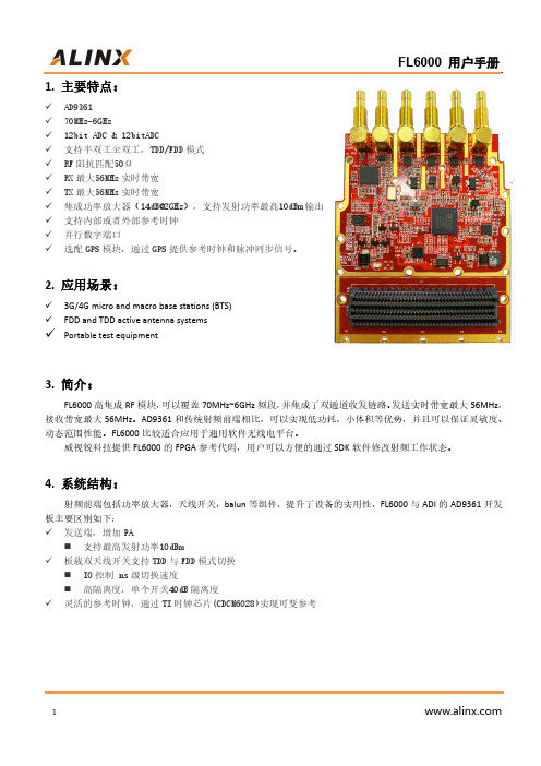
1.主要特点:✓AD9361✓70MHz-6GHz✓12bit ADC&12bitADC✓支持半双工全双工,TDD/FDD模式✓RF阻抗匹配50Ω✓RX最大56MHz实时带宽✓TX最大56MHz实时带宽✓集成功率放大器(14dB@2GHz),支持发射功率最高10dBm输出✓支持内部或者外部参考时钟✓并行数字端口✓选配GPS模块,通过GPS提供参考时钟和脉冲同步信号。
2.应用场景:✓3G/4G micro and macro base stations(BTS)✓FDD and TDD active antenna systems✓Portable test equipment3.简介:FL6000高集成RF模块,可以覆盖70MHz~6GHz频段,并集成了双通道收发链路。
发送实时带宽最大56MHz,接收带宽最大56MHz。
AD9361和传统射频前端相比,可以实现低功耗,小体积等优势,并且可以保证灵敏度、动态范围性能。
FL6000比较适合应用于通用软件无线电平台。
威视锐科技提供FL6000的FPGA参考代码,用户可以方便的通过SDK软件修改射频工作状态。
4.系统结构:射频前端包括功率放大器,天线开关,balun等组件,提升了设备的实用性,FL6000与ADI的AD9361开发板主要区别如下:✓发送端,增加PA⏹支持最高发射功率10dBm✓板载双天线开关支持TDD与FDD模式切换⏹IO控制ns级切换速度⏹高隔离度,单个开关40dB隔离度✓灵活的参考时钟,通过TI时钟芯片(CDCM6028)实现可变参考图1整体框图图2收发切换射频开关名称10TRX-SW TX->TRX TRX->MUX2FDD-TDD-SWRX<-RXMUX1->RX名称10REF_SELREFINGPS module5.射频指标:表1射频指标No.Items Specifications RemarkTx 1Frequency70~6000MHz2Interface SMB3Bandwidth Up to56MHz Tx real-time bandwidth,tunable 4Transmission Power10dBm2500MHz,CW5EVM<2%6Gain Control Range89dB7Gain Step0.25dB8ACLR<-45dBc@10dBm output9Spurious TBD10SSB Suppression35dBc11LO Suppression45dBc12DAC Sample Rate(max)61.44MS/s13DAC Resolution12bitsRx 1Frequency70~6000MHz2Interface SMB3Bandwidth Up to56MHz real-time bandwidth,tunable 4Sensitivity:-90dBm@20MHz5EVM<1.5%6Gain Control Range>60dB7Gain Step1dB8Noise Figure<6dB Maximum RX gain9IIP3(@typ NF)-15dBm10ADC Sample Rate(max)61.44MS/s11ADC Resolution12bits1Voltage 3.3V&12V2ON/OFF TIME<6uS TDD model3Duplexing Model TDD/FDD4Power Consumptions<3W6管脚列表:表2管脚列表信号名称FMC管脚名称FMC管脚方向备注AD9361芯片信号CLOCKOUT LA20_N G22输出可配置时钟输出CTRL_IN0LA26_P D26输出可配置控制信号CTRL_IN1LA22_N G25输出可配置控制信号CTRL_IN2LA21_P H25输出可配置控制信号CTRL_IN3LA25_P G27输出可配置控制信号CTRL_OUT0LA25_N G28输入可配置控制信号CTRL_OUT1LA24_N H29输入可配置控制信号CTRL_OUT2LA21_N H26输入可配置控制信号CTRL_OUT3LA22_P G24输入可配置控制信号CTRL_OUT4LA23_N D24输入可配置控制信号CTRL_OUT5LA24_P H28输入可配置控制信号CTRL_OUT6LA26_N D27输入可配置控制信号CTRL_OUT7LA16_N G19输入可配置控制信号EN_AGC LA16_P G18输入AGC使能控制ENABLE LA19_N H23输入TDD切换控制RESETB LA23_P D23输入低电平复位TXNRX LA17_N_CC D21输入TDD切换控制SPI_CLK LA18_N_CC C23输入SPI总线时钟SPI_CS#LA19_P H22输入SPI总线片选SPI_MISO LA20_P G21输入SPI总线数据SPI_MOSI LA18_P_CC C22输出SPI总线数据SYNC_IN LA17_P_CC D20输入同步触发信号RX_CLK_N CLK0_M2C_N H5输出LVDS数据时钟RX_CLK_P CLK0_M2C_P H4输出LVDS数据时钟RX_FRAME_N LA06_N C11输出LVDS数据帧同步RX_FRAME_P LA06_P C10输出LVDS数据帧同步RXD_N0LA08_N G13输出LVDS数据RXD_N1LA10_N C15输出LVDS数据RXD_N2LA04_N H11输出LVDS数据RXD_N3LA03_N G10输出LVDS数据RXD_N4LA05_N D12输出LVDS数据RXD_N5LA02_N H8输出LVDS数据RXD_P0LA08_P G12输出LVDS数据RXD_P1LA10_P C14输出LVDS数据RXD_P2LA04_P H10输出LVDS数据RXD_P3LA03_P G9输出LVDS数据RXD_P4LA05_P D11输出LVDS数据RXD_P5LA02_P H7输出LVDS数据FB_CLK_N CLK1_M2C_N G3输入LVDS数据回环时钟FB_CLK_P CLK1_M2C_P G2输入LVDS数据回环时钟TX_FRAME_N LA07_N H14输入LVDS数据帧同步TX_FRAME_P LA07_P H13输入LVDS数据帧同步TXD_N0LA12_N G16输入LVDS数据TXD_N1LA11_N H17输入LVDS数据TXD_N2LA13_N D18输入LVDS数据TXD_N3LA14_N C19输入LVDS数据TXD_N4LA15_N H20输入LVDS数据TXD_N5LA09_N D15输入LVDS数据TXD_P0LA12_P G15输入LVDS数据TXD_P1LA11_P H16输入LVDS数据TXD_P2LA13_P D17输入LVDS数据TXD_P3LA14_P C18输入LVDS数据TXD_P4LA15_P H19输入LVDS数据TXD_P5LA09_P D14输入LVDS数据FL6000附加信号CDCM_SPI_CLK LA29_N G31输入CDCM6208SPI配置总线CDCM_SPI_CS LA30_P H34输入CDCM6208SPI配置总线CDCM_SPI_MISO LA31_N G34输入CDCM6208SPI配置总线CDCM_SPI_MOSI LA30_N H35输出CDCM6208SPI配置总线CDCM_SYNC LA33_P G36输入CDCM6208同步触发GPIO_SCL SCL C30双向I2C eeprom AT24CM01GPIO_SDA SDA C31双向I2C eeprom AT24CM01PPS_1SR LA32_N H38输出GPS模块的1ppsREF_SELECT LA29_P G30输入1=外参考,0=内部GPS模块参考REF_SELECT2LA31_P G33输入0=内部VCTCXO晶振,1=外参考或GPS FDDTDD_SW LA28_N H32输入射频开关双工切换TRX_SW LA27_N C27输入射频开关双工切换TXD_GPSR LA32_P H37输出GPS模块UARTRXD_GPSR LA33_N G37输入GPS模块UART所有单端信号电平范围1.8V~2.5V7.FMC供电:扩展模块需要三种电源供电:12V:1A3.3V:1AVADJ:1A1.8V~2.5V8.FL6000尺寸图:图4FMC子板图9.FL6000实物图:图5实物图片10.FL6000典型指标测试:表3P1dB 输出功率频点(MHz)衰减值(mdB)txatt输出功率(dBm)5008e313.110008e312.615006e312.120005e312.925005e31230004e3 6.835002e37.540002e310.445002e310.250002e39.455002e3 6.358002e34.7表4接收5dB增益P1dB输入功率频点(MHz)P1dB输入(dBm) 500-10.81000-11.21500-12.12000-11.82500-73000-2.43500 2.240007.24500-3.15000-3.45500-2.5表5接收70dB增益P1dB输入功率频点(MHz)P1dB输入(dBm)500-65.81000-66.21500-67.12000-66.82500-673000-62.43500-62.34000-57.84500-53.15000-53.45500-58.8表6灵敏度频点(MHz)灵敏度(dBm)500-85.81000-88.21500-87.12000-86.82500-873000-84.43500-84.34000-81.84500-81.15000-82.45500-83.8注:带宽30.72MHz,载噪比门限3.5dB,Y520_50接收增益rx_gain=71表7相位噪声Y520_50200MHz400M1000M2000M2500M3000M3800M4500M5000M5500M 100Hz-86-82-75-71-68-66-6363-62-611KHz-103-99-92-86-85-82-81-80-79-78 10KHz-105-102-95-89-88-85-84-82-81-80 100KHz-115-112-106-99-99-95-94-92-91-901MHz-132-130-127-123-115-116-118-113-114-112。
msdf026-206的参数

一、介绍msdf026-206是一种特定型号的电子设备,具有一定的参数和特性。
该设备常用于某些特定的领域,如航空航天、医疗器械等。
下面将详细介绍msdf026-206的参数及其相关信息。
二、参数列表1. 尺寸:该设备的尺寸为X*Y*Z(单位为mm),适合安装在特定大小的空间中。
2. 重量:msdf026-206的重量为W(单位为kg),比较适合需要轻量化设计的项目。
3. 输入电压:msdf026-206的输入电压范围为V1-V2(单位为V),适合不同电压标准的使用环境。
4. 工作温度:设备的工作温度范围为T1-T2(单位为摄氏度),适合在不同环境温度下的工作条件。
5. 存储温度:msdf026-206的存储温度范围为T3-T4(单位为摄氏度),适合长期储存和运输。
6. 工作湿度:设备的工作湿度范围为H1-H2(单位为RH),适合在不同湿度环境下的工作条件。
7. 存储湿度:msdf026-206的存储湿度范围为H3-H4(单位为RH),适合长期储存和运输。
8. 通信接口:该设备支持的通信接口包括接口1、接口2等,能够满足不同的通讯需求。
9. 数据处理能力:msdf026-206具有较强的数据处理能力,能够高效处理复杂的数据计算和分析。
10. 耐久性:该设备经过严格的耐久性测试,能够在恶劣环境下长时间稳定工作。
三、特性说明1. 高可靠性:msdf026-206经过严格的可靠性测试,具有较高的稳定性和可靠性,能够满足各种严苛的工作环境要求。
2. 低功耗:该设备采用了先进的节能技术,具有较低的功耗特性,能够有效节约能源。
3. 易维护:msdf026-206的结构设计合理,易于维护和维修,能够降低维护成本和周期。
4. 安全性:设备在设计上充分考虑了安全性因素,具有较高的安全性和防护功能。
5. 兼容性:msdf026-206具有良好的兼容性,适合与其他设备进行联动使用,提高系统整体性能。
四、适用领域msdf026-206适用于以下领域:1. 航空航天:该设备具有较强的抗震抗振能力和高可靠性,适合于航空航天领域的数据处理和通讯应用。
ctm澳门wi-fi地址

7-Eleven-筷子基北街
7-Eleven-羅利老馬路
7-Eleven-美景花園
7-Eleven-美景花園
7-Eleven-群安大廈
7-Eleven-興利大廈
7-Eleven-花城
7-Eleven-運順新邨
7-Eleven-金運大廈
7-Eleven-雄昌花園
7-Eleven-高地烏街
7-Eleven-黃金商場
CTM: 澳門Wi-Fi地址
Name(Chinese) 中國銀行澳門分行-永寧廣場分行 中國銀行澳門分行-氹仔支行 中國銀行澳門分行-沙梨頭分行 中國銀行澳門分行-海天居支行 中國銀行澳門分行-海島分行 中國銀行澳門分行-海擎天支行 中國銀行澳門分行-渡船街支行 中國銀行澳門分行-祐漢分行 中國銀行澳門分行-筷子基支行 中國銀行澳門分行-紅街巿分行 中國銀行澳門分行-總行 中國銀行澳門分行-荷蘭園分行 中國銀行澳門分行-連勝支行 中國銀行澳門分行-金沙城支行 中國銀行澳門分行-金海山支行 中國銀行澳門分行-雅廉訪分行 中國銀行澳門分行-高士德分行 中國銀行澳門分行-黑沙環支行 中國銀行澳門分行-龍園支行 中國銀行股份有限公司財富管理中心-濠景花園 中廚 中醫劉健星醫療中心 中銀中小企服務中心-祐漢 二萬軒日式料理火鍋 亞洲遊戲機中心 亞蘇廚房-喜來登廣場 亞蘇廚房-宏信 亞蘇廚房-祐漢 亞蘇廚房-麗駿軒 亨達電訊 京川日式料理 仁匯醫療中心 伊甸園卡拉OK 伍思敏醫療中心 伙工殿咖喱美食 何東圖書館 何毓丹醫療中心 余榮記分店-濠景花園 余榮記分店-至尊花城 余榮記咖啡葡國餐 佛笑樓2-新口岸 佛笑樓-氹仔 佳景樂園-保齡球場 佳景樂園-兒童遊樂場 佳景樂園-大堂 佳景樂園-溜冰場 佳景樂園-麥當勞 佳爵牛扒屋-栢蕙花園 佳爵牛扒屋-筷子基分店 來來電器廣場-下環街分店 來來電器廣場-保利達分店 來來電器廣場-台山分店 來來電器廣場-愉景花園 來來電器廣場-慕拉士旗艦店 來來電器廣場-提督分店 來來電器廣場-樂駿盈軒分店 來來電器廣場-殷皇子分店 來來電器廣場-海濤分店 來來電器廣場-澳門廣場 來來電器廣場-祐新分店 來來電器廣場-美蓮分店 來來電器廣場-聯薪分店 來來電器廣場-賈梅士商業中心 來來電器廣場-金利達分店 來來電器廣場-關閘分店
- 1、下载文档前请自行甄别文档内容的完整性,平台不提供额外的编辑、内容补充、找答案等附加服务。
- 2、"仅部分预览"的文档,不可在线预览部分如存在完整性等问题,可反馈申请退款(可完整预览的文档不适用该条件!)。
- 3、如文档侵犯您的权益,请联系客服反馈,我们会尽快为您处理(人工客服工作时间:9:00-18:30)。
(Ta=25℃) Rating
100 60 5 1 100 40 30 5 -20 ~ +85 -30 ~ +85 260
Unit
mW mA V A mW mA V V ℃ ℃ ℃
Applications
•Facsimiles •Printers •Scanner •Copies •Amusement machines
Typ.
1.2 940 1 1.5 0.5 0.15 4 5
Max.
1.4 10 100 10 10 0.4 -
Unit
V uA nm nA mA uA V usec usec
Swithching S 2006 Rev 1.0
FI-206S
光電企業有限公司
*1. pulse width : tw ≦100usec. Period : t = 10msec *2. For MAX. 5seconds at the position of 2mm from the resin edge
ELECTRO-OPTICAL CHARACTERISTICS
Item
APPLICATION CIRCUIT
光電企業有限公司
3 ± 0.2
December 2006 Rev 1.0
December 2006 Rev 1.0
FI-206S
DIMEMSIONS
NOTES : 1. All dimensions are in millimeters. 2. Tolerance is ±0.25mm unless otherwise specified. 3. Specifications are subject to change without notice.
(Ta=25℃) Min.
0.5 -
Symbol
VF IR λp ICEO IC ICEOD VCE(sat) tr tf
Conditions
IF=20mA VR=5V IF=20mA VCE=10V IF=20mA,VCE=5V (Non-shading) IF=20mA,VCE=5V (Shading) IF=20mA,IC=0.1mA Vcc=5V,Ic=2mA RL=100Ω
Features
•PWB direct mount type •GAP:5.0mm •With the installation positioning boss •Low cost •Meet RoHS
MAXIMUM RATINGS
Item Symbol
PD IF VR IFP PC IC VCEO VECO Topr. Tstg. Tsol.
Input Output Forward voltage Reverse current Peak wavelength Collector dark current Light current Transmission Leakage current C-E saturation voltage Rise time Fall time
Power dissipation Forward current Input Reverse voltage Pulse forward current *1 Collector power dissipation Collector current Output Collector-Emitter voltage Emitter-Collector voltage Operating temp. Storage temp. Soldering temp. *2
FI-206S
PHOTO INTERRUPTER (Transmission)
General Description
The FI-206S is Photo-Interrupter high-performance standard type. combines high-output GaAs IRED with high sensitive Photo-transistor.
