X25F008等
海尔遥控器对照表(大全)

39 HYF-25 HS-2168,HS-3708E,HS-2188
40 HYF-24G HP-2159(100P) CD4000386
41 HYF-25C HS-2158B CD4000106
11 HYF-28D HT-2199,HT-2199B,HS-2198(100), CD4000268 28A
12 HT-2599,21F99,HP-2159,HT-2119 CD4000268 28A
13 HYF-29A 29T6A-P,29F1A-P(拉幕式),29F6A-P CD4000929 34A
30 HYF-24C HP-2981C,HP-2188,HP-2559 CD4000779
31 HYF-24E HS-2968,HS-2528,HS-2528D,HS-2918D CD4000251
32 HYF-31A 29F66(100P) CD4001080
33 HYF-33C HP-2928,HP-2928B,HS-2579C,HP-2128,HP-2989A1, CD4000782
67 HYF-31D 29F69,HP-2988,29F90,29TA,29FA,29TB CD4000158
4 X. E& M7 w4 |. }, k+ ]遥控器型号与机 型对照表(其他)精品图纸网7 R" p* T$ L3 S! q/ \! R3 R* x% ~$ {
第3页
序号 遥控器型号 机型 产地
H-2999,H-2999A,H-3498 N-99-001-004 惠州长城
GD错误代号列表
机器类型(意大利、每台机器有两个OPC、比较新的机型)1、返回的温度数据:6417协议格式:64(帧头)+17(温度传送功能码)+(0000-1000)温度组号+9100(温度设定值,低字节在前,高字节在后)+9000(实际温度值,低字节在前,高字节在后)+000000(3字节,分别对应于温度值显示框上的CWD值,字节值为00时,CWD 值显示为绿色,01时显示黄色、02时显示红色、其他值显示绿色,分别表示恒温器的(C、W、D 检查、运作、诊断状态)6417(传送温度值代码)传送CWD(温度)值的号码:00、01、03、04、05、06、07、08、09、0a、0b、0c、0d、0e、0f、10 (应该是有17组值,但是监测数据没有发现02号的值,可能为16组)(CH页面温度值,共2列,4行,右边1位置没有温度值)00:CH页面,2列,2行,前一个对应上面的温度值,后一个对应下面的温度值。
01:CH页面,1列,1行,02:CH页面,1列,2行,03:CH页面,1列,3行,04:CH页面,2列,3行,05:CH页面,1列,4行,06:CH页面,2列,4行,07:CT页面,2列,2行,08:CT页面,1列,2行,09:CT页面,3列,2行,0a:CT页面,1列,1行,0b:CT页面,2列,1行,0c:CT页面,1列,3行,0d:X2页面,1列,1行,2、返回的速度数据:6400协议格式:64(帧头)+00(速度传送功能码)+(00、01、02)三组速度,00 CH页面下的速度值;01 CT页面下的速度值;02 X2页面下的速度值;+ 0001(指示机器的运行方向)0001,显示速度值,此时概要图的显示框中显示的是速度值,右边箭头为红色0002,显示速度值,此时概要图的显示框中显示的是速度值,左边箭头为红色0000,此时概要图中的显示框中显示的是绝对编码器的位置+ffff (绝对编码器的位置值)当速度非0时,没有停止,则值为ffff,没有实际意义;当速度为0时,值为0800、0a00、7500、7b00…..,表示绝对编码器的位置,便于停机后,根据值,对机器进行调整。
常用肖特基二极管型号
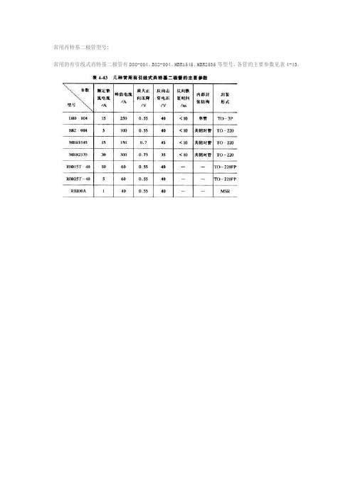
常用肖特基二极管型号:常用的有引线式肖特基二极管有D80-004、B82-004、MBR1545、MBR2535等型号,各管的主要参数见表4-43。
常用的表面封装肖特基二极管有FB系列,其主要参数见表4-44。
特基二极管F5KQ100F5KQ100肖特基二极管30CPQ14030CPQ140肖特基二极管30CPQ10030CPQ100肖特基二极管30CPQ09030CPQ090肖特基二极管30CPQ06030CPQ060肖特基二极管30CPQ04530CPQ045肖特基二极管MBRS260T3GMBRS260T3G肖特基二极管MBRS130T3GMBRS130T3G肖特基二极管MBRS320T3GMBRS320T3G肖特基二极管MBRS340T3GMBRS340T3G肖特基二极管MBRS140T3GMBRS140T3G肖特基二极管MBRS240LT3MBRS240LT3肖特基二极管MBRS230LT3MBRS230LT3肖特基二极管MBRS2040LTMBRS2040LT肖特基二极管MBR20100MBR20100肖特基二极管MBR3045MBR3045肖特基二极管MBR2545MBR2545肖特基二极管MBR2045MBR2045肖特基二极管MBR1545MBR1545肖特基二极管MBR1045MBR1045肖特基二极管MBR745MBR745肖特基二极管MBR3100MBR3100肖特基二极管MBR360MBR360肖特基二极管DSC01232DSC01232肖特基二极管SB3040SB3040肖特基二极管IN5817IN5817肖特基二极管IN5819IN5819肖特基二极管IN5818IN5818肖特基二极管IN5822IN5822肖特基二极管HER107HER107肖特基二极管HER207HER207肖特基二极管HER307HER307肖特基二极管FR105FR105肖特基二极管FR2050。
常用肖特基二极管型号及参数
常用肖特基二极管型号及参数肖特基二极管是一种特殊的二极管,由于其具有较高的开关速度和低的开启电压,被广泛应用于电子领域中的高频电路、开关电路和功率放大电路等。
本文将介绍几种常用的肖特基二极管型号及其参数。
1. 1N58171N5817是一种常用的肖特基二极管,其最大反向电压为20V,最大正向电流为1A。
它具有快速恢复特性和低的正向压降,适用于高频开关电源和充电电路。
2. 1N58221N5822是一种常见的肖特基二极管,其最大反向电压为40V,最大正向电流为3A。
该型号的二极管具有较低的正向压降和较高的开关速度,适用于高频开关电源、稳压电路和逆变电路。
3. SR5100SR5100是一种高性能的肖特基二极管,其最大反向电压为100V,最大正向电流为5A。
该型号的二极管具有较低的反向电流和较高的开关速度,适用于高频开关电源、电机驱动和电源逆变器等应用。
4. BAT54BAT54是一种超小封装的肖特基二极管,其最大反向电压为30V,最大正向电流为200mA。
该型号的二极管具有快速恢复特性和低的正向压降,适用于便携式电子产品、无线通信和电源管理等领域。
5. SB5150SB5150是一种高性能的肖特基二极管,其最大反向电压为150V,最大正向电流为5A。
该型号的二极管具有较低的反向电流和较高的开关速度,适用于高频开关电源、电机驱动和电源逆变器等应用。
6. MBR20100CTMBR20100CT是一种高功率的肖特基二极管,其最大反向电压为100V,最大正向电流为20A。
该型号的二极管具有快速恢复特性和低的正向压降,适用于高功率开关电源、电机驱动和逆变器等高要求的应用。
肖特基二极管是一种具有快速恢复特性和低的正向压降的二极管。
常用的肖特基二极管型号包括1N5817、1N5822、SR5100、BAT54、SB5150和MBR20100CT等。
这些二极管具有不同的最大反向电压和最大正向电流,适用于不同的应用场景。
SPI总线在51系列单片机系统中的实现(一)

SPI总线在51系列单片机系统中的实现(一)摘要:MCS51系列、MCS96系列等单片机由于都不带SPI串行总线接口而限制了其在SPI总线接口器件的使用。
文中介绍了SPI串行总线的特征和时序,并以串行E2PROM为例,给出了在51系列单片机上利用I/O口线实现SPI串行总线接口的方法和软件设计程序。
关键词:单片机SPI串行总线总线接口1引言SPI(SerialPeripheralInterface--串行外设接口)总线系统是一种同步串行外设接口,它可以使MCU与各种外围设备以串行方式进行通信以交换信息。
外围设置FLASHRAM、网络控制器、LCD显示驱动器、A/D转换器和MCU等。
SPI总线系统可直接与各个厂家生产的多种标准外围器件直接接口,该接口一般使用4条线:串行时钟线(SCK)、主机输入/从机输出数据线MISO、主机输出/从机输入数据线MOST和低电平有效的从机选择线SS(有的SPI接口芯片带有中断信号线INT或INT、有的SPI接口芯片没有主机输出/从机输入数据线MOSI)。
由于SPI系统总线一共只需3~4位数据线和控制即可实现与具有SPI总线接口功能的各种I/O器件进行接口,而扩展并行总线则需要8根数据线、8~16位地址线、2~3位控制线,因此,采用SPI总线接口可以简化电路设计,节省很多常规电路中的接口器件和I/O口线,提高设计的可靠性。
由此可见,在MCS51系列等不具有SPI接口的单片机组成的智能仪器和工业测控系统中,当传输速度要求不是太高时,使用SPI总线可以增加应用系统接口器件的种类,提高应用系统的性能。
2SPI总线的组成利用SPI总线可在软件的控制下构成各种系统。
如1个主MCU和几个从MCU、几个从MCU相互连接构成多主机系统(分布式系统)、1个主MCU和1个或几个从I/O设备所构成的各种系统等。
在大多数应用场合,可使用1个MCU作为控机来控制数据,并向1个或几个从外围器件传送该数据。
Celestron EdgeHD 1100 0.7x Reducer Lens Instructio

Figure 1 – Optimum Spacing for EdgeHD 9.25/11/14Instruction Manual – Model #94241.7x Reducer Lens – EdgeHD 1100Your .7x reducer lens makes your EdgeHD 1100 telescope onefull F-Stop faster than at f/10. Photographically this will enable youto reduce your exposure times by one-half and still capture thesame amount of light, while providing a 43% wider fi eld of view.Celestron LLC • 2835 Columbia Street • Torrance, CA 90503Phone: 310.328.9560 • Fax: 310.212.5835©2012 Celestron • All rights reserved. #94241-INST 08-12Warranty: Two year limited warranty.For complete warranty details contact Celestron or visit: Attaching the Reducer 1. Remove the visual back and adapter plate from the rear of the telescope.2. The focal reducer threads directly onto the rear baffl e locknut (see Figure 1) of your EdgeHD telescope.3. Attach your T-Adapter (#93646, sold separately) onto the rear threads of the focal reducer.Camera SpacingSince the optimal photographic back focus of 146 mm is thesame with or without the focal reducer attached, the optional #93646 T-Adapter can be used to attach the Nightscape CCD Camera, DSLR body or any other camera with 55 mm of back focus.For best performance, it is highly recommended that you position your camera as close to the recommended optimalspacing as possible. It is best to maintain optimal spacingto within 1-3 mm depending on the size of your imagingsensor. As your imaging chip gets larger (farther off-axis), maintaining optimal spacing becomes more critical. Being inside of focus (too short) tends to affect the outermost edgeof the fi eld of view when using a relatively large sensor(17 mm or greater). Being outside of focus (too long) tendsto produce elongated star images towards the edge and could run the risk of running out of focus travel on yourEdgeHD optical tube. In general it is better to be slightly inside of focus than outside of focus.Focal lengths for the EdgeHD 1100 in its native format (f/10), with the .7x Reducer Lens and with optional f/2lens assembly.。
fu25电子管参数
fu25电子管参数
FU25电子管参数:
1. 中心角频率:这是一种大功率三极管,其中心角频率为450 kHz。
2. 静态输入阻抗:FIU25的静态输入阻抗约为800 ohms,远低于必须抵抗差分变换的管子。
3. 最大散热器功率:散热器上可安装的最大功率为25瓦,可以满足大功率的应用
需求。
4. 钳位电压:最大钳位电压为700 V。
5. 共模输出:FIU25共模输出电压约为21 V,电流约为2.6 A。
6. 三极管电容:FIU25中极管电容为最大6 pF。
7. 输出动态阻抗:FIU25的输出动态阻抗约为7.5 ohms,可以抵抗高频信号的变化。
8. 最大工作温度:FIU25最大工作温度约为175摄氏度。
9. 中继电压:FIU25中继电压最大为200 V。
10. 旁路电容:FIU25旁路电容约为2.2 pF。
FU25电子管是一种大功率三极管,它具有良好的散热性能,具有较高的功率
使用寿命,其性能参数如下:
FU25电子管在有效抵抗差分变换所需的抗串联阻抗的同时,具有很高的功率
使用寿命、散热性能等性能优势,是一种很受欢迎的大功率三极管。
它的输出电压和电流均更高,可以满足更高功率应用的需求。
另外,FIU25的三极管电容仅为
6pF,可以克服噪音问题,从而更加准确地处理信号,并可以提供更加便捷的数据
传输。
FIU25的最大钳位电压也增加到700V,这也是该大功率三极管非常受欢迎
的一个很大原因。
理论最大相对密度

沥青混合料拌和均匀(油石比4.6%)
合同号: DZX13-6标 编号: 试 试 试 复 验 验 验 核 环 设 人 人 境 备 员 员
最大理论密度gcm3试样理论最大相对密度平均值试样理论最大相对密度试样在25水中理论最大密度测值trtwgcm3负压容器在25水中质量m1g干燥试样在空气中质量mag试样编号试验规程jtge202011t07112011试验人员沥青混合料拌和均匀油石比4
沥青混合料理论最大相对密度试验(真空法)记录表
ma ma -( m2 - m1 )
rt m m a m B、C类: a b c
m
1 BC 2
2677.8
/
/
5867.9
7489.6
2.536 2.539
2.529 2.532 2.534
2666.6
/
/
5848.7
7465.7
2.541
结论:该样品试验(本试验采用真空法)理论最大相对密度为2.519。
20131019LH01-03 试表2-23 湿度42%
温度20℃
天平(HX-008) 、理论密度仪(LH沥青种类 试样编号
A级70#道路石油沥青 /
AC-25F
试样理论最大相对密度 负压容 干燥试 负压容 器与试 容 样在空 器在25 器 试样 气中质 ℃水中 样在25 ℃水中 类 编号 量 质量 m1 质量 型 ma(g) (g) m2(g) 装满25 ℃水的 负压容 器质量 mb(g) 试样、 水、负 压容器 总质量 mc(g) A类: rt 试样在25℃ 水中理论最 最大理论密 大密度测值 3 ρ t=rt×ρ 度(g/cm ) 3 试样理 w(g/cm ) 论最大 相对密 度平均 值
大学俄语简明教程答案

大学俄语简明教程答案【篇一:俄语网站】提供给大家几十本实用的俄语电子书供大家下载,本电子书请用emule(电驴)下载电驴软件下载地址:请复制各书名下“ed2k://........|/”连接地址,本p2p软件下载的人越多越快,另外电驴软件使用方法及更多下载资源请订阅《疯狂俄语》(免费)电子杂志我们将在大多时间作“种子”供大家下载第一次推出书目:出国留学人员俄语强化教学大纲大学俄语词汇语法精解(修订本)ed2k://|file|rus008.rar|14327000|5cfeaecdd3b6959e02cf2730b74fd30d|h=whnvd34m3pvm4wmxxv26xuzxalmvwmtu|/大学俄语高级听力训练ed2k://|file|rus009.rar|5977156|163a18bbed601446a6dc2651250 591c1|h=dogn537gzhbxhwxuz476ma5ibk4sxo4r|/大学俄语简明教程(第二外语用)ed2k://|file|rus011.rar|7727719|e8f468769abb9d1e3f4fbe7a60ddd672|h=4xt3uf7y27dc4im5krhycp6nxayj2e7a|/大学俄语科技阅读基础ed2k://|file|rus012.rar|14413366|c5114819454feab3188141a8874e5a9f|h=h3nfgpbmvwefbyjfh323i2puwpwytwdj|/大学俄语四级考试练习题集d8aa4e2cb7dda30f30d983167004ac40|h=sbek4pcgk76nwtrc624 zql7hgbftxzbi|/大学俄语四级考试模拟试集ed2k://|file|rus014.rar|6452878|08a03364a65a30c8c400757f7a07e3dd|h=falhukuhxpeqqmir4nmljjnligrrgnza|/大学俄语听力(上)(一、二级)ed2k://|file|rus015.rar|5973852|9022a65e242df131c84a9e0497bf cf98|h=yvtljha2yiqzqejrdfup7p5sqkmpko2o|/大学俄语听力(下)(三、四级)ed2k://|file|rus016.rar|6888131|76b04ee433234750a2e9ce4e708 e48b0|h=yk57qqktz72s6ellwfoefrimuccqsfac|/大学俄语听说教程教学参考书ed2k://|file|rus017.rar|9423514|df50c6ca9608490abe16afc8b1ce 5d4d|h=zb472gd22qpbzlp3ia2llhrtfjscm2yl|/大学俄语系参考书大学俄语翻译精粹ed2k://|file|rus018.rar|9317357|13498b185aa6c166a0ec0393543 6cf0a|h=tmpahhflhgumbbx5roq6ugzennivuy2y|/大学俄语系列参考书ed2k://|file|rus019.rar|8405380|7779ac6bb0da874ca412b13388d edf15|h=hekc5yi4tamcjutipci3orn2eb5an6mx|/大学俄语系列参考书大学俄语四级模拟测试(修订本)ed2k://|file|rus020.rar|6796384|11d2162971d9e65a19f6bef4f60f0 a5e|h=c55fe5ab65pgz2m2ywae32r6wpsfjdei|/大学俄语系列参考书大学俄语阅读精选ed2k://|file|rus021.rar|7552444|4131779ec1c8caeb1b45d4eab2b a85e6|h=plhyrdlqil6yblo2kxtrgbrhkdmdgkjy|/大学俄语系列参考书大学俄语阅读精选(修订本)ed2k://|file|rus022.rar|7898980|23fe536bba30980d57745f59a7c6 c8f8|h=eff4vry3xgu46rlhosa7r2hrab22dhey|/大学俄语系列参考书大学俄语综合练习修订本ed2k://|file|rus023.rar|8056692|6502b2ee0c02a0a25f58335c3564 f973|h=to3zev72vaoqittvgksw5rfrswbndupi|/大学俄语系列参考书俄语考研模拟试题集ed2k://|file|rus024.rar|7026993|b43bc531960ba020e74b4df37c7 71143|h=sliutdy2chcdmsmvvvtfxra4b2fjqnhp|/大学俄语系列参考书俄语历届考研真题详解修订本ed2k://|file|rus025.rar|8573065|4fdd99c0183dcbc50683aad41d3 26f44|h=z5c2i74724bimg7x5nnpum37z3kevbff|/大学俄语写作高分突破与技巧ed2k://|file|rus026.rar|7249655|3b8ec7ce1e8a5a5f21f0bc2739ee 7067|h=uesxvjbjtofkda7qxv4nlh7nx73dtdcv|/大学俄语阅读文选ed2k://|file|rus027.rar|7869988|e8e4a56de22fcead6a5baa780544 29a2|h=7fp4ymffr2x7ki5glqrjcpwct5mxbfq2|/大学俄语阅读与写作(上册)ed2k://|file|rus028.rar|6638561|f0c5041cbddb15d7bcb06bac4afc 4785|h=fxmalmpi7c4vsx2jwuctwnl7ajk4szwy|/大学俄语专业四级考试模拟试题集ed2k://|file|rus029.rar|12852407|513a93ee06d7c8289808640b5b 499804|h=3fg626zosio2acyye2pqsr5qr7p4uml5|/大学俄语综合阅读选粹ed2k://|file|rus030.rar|8843599|3a504504d05732f9e7795b2ae28b 4ab9|h=5n6ecw2fgnqm5a6iplhtrryyf6eaqkrh|/俄语常用词快速记忆ed2k://|file|rus034.rar|9250238|009ab700582b6a87f61e1e67916f 8caa|h=4aoblgosptl34cvjqx4hgfr6oryvegvm|/俄语考试指南ed2k://|file|rus039.rar|7245117|3c6e8022921f2aacf37326b49ee1 d7e8|h=xgu46zn22xg5xut7anshiespbw67suh5|/俄语考试指南下册ed2k://|file|rus040.rar|11585817|ef09647054580709066330b05c3 f7644|h=kbz25dfq3aadi5dnxx5bqd2xkep3j6ip|/俄语四级考试指导及强化训练ed2k://|file|rus045.rar|10987138|4b2b5f654585cff4580f23bb549c f78b|h=wmp5txl4xwrdv3q5tqyhsbdzybdyr64i|/liosha 2004-11-2 07:27第二次推出书目俄语现代口语及应用文俄汉对照ed2k://|file|rus046.rar|9002811|2dab05e796f4451953d58262bc1c 2786|h=vvnddzzurdfkyu7frqr5eqodmycjo5zw|/军队专业技术干部俄语考试指南ed2k://|file|rus057.rar|10341457|20aab040180afca9cdada4d3030 76eb2|h=git4xcuv2r22yeplvsrpgsjuwjiddrer|/全国专业技术人员职称俄语等级考试辅导ed2k://|file|rus058.rar|12867599|c8ca159d06f8279ef7f207a1cb61 78de|h=cqnds7hcpecksofgzf6kjasshah35ey7|/全国专业技术人员职称俄语等级考试大纲ed2k://|file|rus059.rar|6591837|079cd99483737d64cc40e6e2857 3e1be|h=3h7nkpcfr3gwc7xfi5mvrsai33hqgdt5|/北京俄语导游ed2k://|file|rus005.rar|7630274|f05b572b94b868228c92fda4ba98 8372|h=yrvbw6zetp2c5fucb56mhj3hbl4ewiyp|/俄汉对照365ed2k://|file|rus031.rar|4701634|8f9fa8db32aaec495b7dcf08f21dd bfd|h=uiseujpkqytxfkacc6sbolcl64a6iyhu|/俄汉会话ed2k://|file|rus032.rar|5083313|1767e79130208a30e3f8c48d5d6d 64bf|h=ywgcm7njfa7b4yxothvivs73wi2qf44p|/俄汉英会话ed2k://|file|rus033.rar|6353856|6a8f1597fc1d535fb8cb4d2f0d925 4aa|h=6fx27cdvguh73q7dbhd5f6qhyc4ea2fc|/俄汉语言文化习俗探讨ed2k://|file|rus004.rar|8357451|15556a094845adafe3ba1e350d04 4ed8|h=xqhn5xidufeibh7y3ngqljqsts2flq5o|/俄语1000句ed2k://|file|rus003.rar|7029946|c67cc6d6d3cc328624cb7858a5fc 70f1|h=e5z6vacnei6usi6wkuvgwgvc3z34py34|/俄语报刊阅读ed2k://|file|rus002.rar|8380404|39b6d38e82a49066360bbaaa4f07 47ba|h=t7wattvaynuahwznv5qhirmbwvlog5vd|/俄语词汇修辞ed2k://|file|rus001.rar|6425346|e5ff1ac84b5608bc36c0a3697ba0 cd81|h=7dga6umjnjmbd4hf5k64c62tx4w4op6z|/俄语对外经贸文牍ed2k://|file|rus035.rar|7687945|af48acc4915afdda56776be8c6b9 28fe|h=i74q5ncbi2lhe7onchzoxf4ppc2gv7qt|/俄语发音基础学习ed2k://|file|rus036.rar|4449581|5551bb0f681765d8be5971709ca8 a9f9|h=5kapwxmhdcvc76ib2e35twusmcbqrc37|/俄语会话重复反应语句交际语用研究ed2k://|file|rus037.rar|8093360|750f3f94bbbe952249fe8d3e9c22 b81c|h=nhwtatomwgxttvzdc43jrflitdeywvro|/俄语经贸文章选读ed2k://|file|rus038.rar|6278559|78479756f9fa958003fbb2d7a925 d644|h=2uhbpqvogsiub5ohhjoyom26jjl5qugs|/俄语口语形态学ed2k://|file|rus041.rar|10910022|b3d637ccfc85fd0572f4aec8e50 713cc|h=w6litpmfn2tc2nwknplom7a662atmsvd|/俄语快速阅读ed2k://|file|rus042.rar|9555746|727bc24ac5f457dfd9b448d1ded0 6a7f|h=5tacavg6vdqvyjmvz74v26yrbpp6ehu5|/俄语情景会话ed2k://|file|rus043.rar|6843228|ae25744f31222383da4e09a47e77 38de|h=fd52hyr6v4fcqpou4eqimlh6pb2myife|/俄语三百句ed2k://|file|rus044.rar|5288033|a3ad8cc419ffebfca6667e0b45250e81|h=p6khqyv2cvnjihwjfjkvlwdqs2i47me3|/俄语学习背景知识ed2k://|file|rus047.rar|3935693|511de57a66868b732d868e920be 01e54|h=3qwjf7un4bkaohupcvgklgd6ssmfmqqc|/俄语语体研究ed2k://|file|rus048.rar|10084297|867c3be15128472cf404ec0c4a5 21d62|h=klrpnbctin3p7whjas2dituz2p7jkxez|/俄语语音学教程ed2k://|file|rus049.rar|7152786|807d78ffd4feb076306b634ee2416f07|h=ef3w2x3ysr6ogrmcjks5iyd5q3sbq22r|/高等学校教材俄语与俄罗斯文化【篇二:俄语入门教学大纲】>课程名称:俄语入门课程编码:p0701003适用专业及层次:本校所有学生课程总学时:32学时课程总学分:2学分理论学时:32学时实践学时:0学时先修课程:无一、课程的性质、目的与任务《俄语入门》是一门公共选修课程。
KF8F204数据手册V1.0
17
I/O
T0CK
INT0
P0.1
AN1
18
I/O
ADVRIN
SPCLK
P0.0
19
I/O AN0
SPDAT
20
P VSS
KF8F204 数据手册 V1.0
双向输入输出端口 ADC 输入通道 8 双向输入输出端口 ADC 输入通道 6 外部中断 1 输入 双向输入输出端口 ADC 输入通道 5 双向输入输出端口 ADC 输入通道 4 PWM1 输出 带上拉和电平变化中断功能的双向输入输出端口 ADC 输入通道 2 T0 时钟输入 外部中断 0 输入 带上拉和电平变化中断功能的双向输入输出端口 ADC 输入通道 1 AD 外部参考电压输入 在线编程时钟输入 带上拉和电平变化中断功能的双向输入输出端口 ADC 输入通道 0 在线编程数据输入 地,0V 参考点
2.2.2 P1 口原理功能框图 .....................................................26 2.3 P2 口 .....................................................................27
2 I/O端口介绍 ............................................................... 17
2.1 P0 口 .....................................................................18 2.1.1 P0 口相关的寄存器 .....................................................19
SST25VF080B 中文手册

8兆位的SPI串行闪存A Microchip Technology CompanySST25VF080BSST公司的25系列串行闪存系列具有四线SPI兼容跨面对这允许一个低引脚数封装占用的电路板空间并最终降低总系统成本.该SST25VF080B设备加强与改进工作频率从而降低功耗化. SST25VF080B SPI串行闪存采用SST公司生产的专有的,高性能CMOS SuperFlash技术.分裂闸电池设计和厚氧化物隧道喷油器达到更好的可靠性和马努-与其他方法相比facturability产品特点:•单电压读写操作– 2.7-3.6V•自动地址递增(AAI)编程- 降低整个芯片的编程时间超过字节亲克操作•串行接口架构- 兼容SPI:模式0和模式3写操作结束的•检测- 软件轮询状态寄存器中的BUSY位- SO引脚在AAI模式上忙状态读出•高速时钟频率- 50/66号MHz的条件(见表15)- (SST25VF080B-50-xx-xxxx)- 80 MHz的- (SST25VF080B-80-xx-xxxx)•保持引脚(HOLD#)- 挂起一个串行序列的记忆没有取消选择该设备•卓越的可靠性- 耐力:100,000周期(典型值)- 大于100年数据保存期•写保护(WP#)- 启用/禁用状态的锁断功能注册•低功耗:- 有效的读电流:10 mA(典型值)- 待机电流:5μA(典型值)•软件写保护- 通过写块保护位的保护状态注册•灵活的擦除功能- 统一的4 K字节部门- 统一32 K字节块重叠- 统一64 K字节块重叠•温度范围- 商业:0°C至+70°C- 工业级:-40°C至+85°C•快速擦除和字节编程:- 芯片擦除时间:35 ms(典型值)- Sector-/Block-Erase时间:18毫秒(典型值)- 字节编程时间:7μs(典型值)•可用的软件包- 8引脚SOIC(200密耳)- 8引脚SOIC(150密耳)- 8触点WSON(6毫米×5毫米)- 8引脚PDIP(300密耳)产品描述SST公司的25系列串行闪存系列具有四线SPI兼容接口,允许低引脚数封装占用的电路板空间,并最终降低总系统成本.该SST25VF080B设备加强与改进工作频率和更低的功耗,化. SST25VF080B SPI串行闪存采用SST专有的,高性生产曼斯CMOS SuperFlash技术.分裂门电池设计和厚氧化物隧道注射器实现更高的可靠性和可制造性与替代方法.该SST25VF080B器件显著提高性能和可靠性,同时降低功耗消费.该设备写(编程或擦除)与2.7-3.6V的单电源供电SST25VF080B.所消耗的总能量是所施加的电压,电流和应用的时间的函数.因为对于任何给定的电压范围,SuperFlash技术使用较少的编程电流和有一个较短的擦除时间,在任何擦除或编程操作消耗的总能量小于其他闪存技术.该SST25VF080B器件采用8引脚SOIC提供(200密耳),8引脚SOIC(150密耳),8 - 接触WSON(6毫米×5毫米),和8引脚PDIP(300密耳)封装.参见图2引脚分配存储器结构该SST25VF080B超快闪存储器阵列的统一4 K字节可擦除扇区32K字节覆盖块和64 K字节覆盖可擦除块.设备操作该SST25VF080B通过SPI(串行外设接口)总线兼容的协议来访问.SPI总线包括四个控制线;芯片使能(CE#)用于选择该设备,数据通过串行数据输入(SI),串行数据输出(SO)和串行时钟(SCK)进行访问.该SST25VF080B支持模式0(0,0)和模式3(1,1)SPI总线操作.所不同的在两个模式之间,如图3所示,是在SCK信号的状态时,该总线主机在待机模式并没有数据正在传输. SCK信号是低模式0和SCK信号为高电平模式3.对于这两种模式,串行数据输入(SI)进行采样,在SCK时钟信号和串行数据输出的上升沿(SO)后驱动在SCK时钟信号的下降沿.保持操作在按住#引脚用于暂停串行序列正在进行与SPI闪存没有复位,婷定时序列.要启动按住#模式,CE#必须在低电平状态.在HOLD#模式时,SCK低电平状态恰逢HOLD#信号的下降沿开始.该HOLD模式当HOLD#信号的上升沿与SCK低电平状态恰逢结束.如果HOLD#信号的下降沿不与SCK低电平状态,则设备一致进入保持模式当SCK未来达到低电平状态.类似地,如果在上升沿HOLD#信号不与SCK低电平状态保持一致,然后在保持模式器件退出当SCK未来达到低电平状态.参见图4为保持状态的波形.一旦设备进入保持模式,因此将在高阻抗状态,而SI和SCK可以VIL或VIH.如果CE#是在一个保持状态驱动的主动高,它重置设备的内部逻辑.只要HOLD#信号为低,内存仍然在保持状态.要恢复与设备通信,按住#必须积极推动高,CE#必须被驱动低电平有效.参见图24为保持时间。
第8章80C51的串行总线扩展

MSB
D6 D5~D2 D1
LSB
单片机读(从器件输出)时,在选通有效的情况下,SCK的下降 沿时从器件将数据放在MISO线上,单片机延时并采样MISO线,将 数据位读入。然后将SCK置为高电平形成上升沿,数据被锁存。
单片机写(从器件输入)操作类似。
2020/5/9
20
【例8-3】单片机与具有SPI总线接口的E2PROM器件X25F008的
2020/5/9
13
基本操作子程序
1.应答位检查 (正常操作时F0标志为 “0”,否则为“1”) ASKC:SETB SDA
SETB SCL CLR F0;预设F0=0 MOV C,SDA JNC EXIT;应答正常 SETB F0 ;应答不正常 EXIT:CLR SCL RET
2.发送一个字节(先将欲发送的数据送入A中)
它可以使具有I2C总线的单片机(如PHILIPS公司的8xC552 )直接 与具有I2C总线接口的各种扩展器件(如存储器、I/O口、A/D、D/A、 键盘、显示器、日历/时钟)连接。
对不带有I2C接口的单片机(如89C51)可采用普通的I/O口结合软 件模拟I2C串行接口总线时序的方法,完成I2C总线的串行接口功能。
MOV @R0,#11H INC R0 MOV @R0,#22H
RET END
R0 @R0,#33H R0 @R0,#44H R0 @R0,#55H R0 @R0,#66H R0 @R0,#77H R0
2020/5/9
17
【例8-2】接口电路如前图所 示。编程实现从AT24C02的50H57H单元读出8个字节数据,并 将其存入内部RAM的40H-47H单 元。
2020/5/9
15
5.读取n个字节(由E2PROM) 入口条件:R1发送缓冲区首址
FX5用户手册(MODBUS通信篇)

第4章
4.1
MODBUS通信规格
16
MODBUS协议 . . . . . . . . . . . . . . . . . . . . . . . . . . . . . . . . . . . . . . . . . . .16 帧模式 . . . . . . . . . . . . . . . . . . . . . . . . . . . . . . . . . . . . . . . . . . . . . 17 MODBUS标准功能对应一览 . . . . . . . . . . . . . . . . . . . . . . . . . . . . . . . . . . . . . 17
【配线注意事项】 警告
● 进行安装、接线等作业时,请务必在外部将所有电源均断开后方可进行操作。否则有触电、产品损坏 的危险。 ● 在安装、接线等作业后执行上电运行时,请务必在产品上安装附带的接线端子盖板。否则有触电的危 险性。 ● 请使用额定温度超过80℃的电线。 ● 对欧式端子排型的产品进行接线时,请遵照以下的注意事项操作。否则有可能导致触电、故障、短 路、断线、误动作、损坏产品。 - 请依据手册中记载的尺寸对电线的末端进行处理。 - 紧固扭矩请依照手册中记载的扭矩。 - 绞线的末端要捻成没有金属丝发散。 - 请勿对电线的末端上锡。 - 请勿连接不符合规定尺寸的电线或是超出规定根数的电线。 - 请不要对端子排或者电线的连接部分直接施力进行电线固定。
使用时的请求
• 产品是以一般的工业为对象制作的通用产品,因此不是以用于关系到人身安全之类的情况下使用的机器或是系统为目的而设 计、制造的产品。 • 讨论将该产品用于原子能用、电力用、航空宇宙用、医疗用、搭乘移动物体用的机器或是系统等特殊用途的时候,请与本公 司的营业窗口查询。 • 虽然该产品是在严格的质量体系下生产的,但是用于那些因该产品的故障而可能导致的重大故障或是产生损失的设备的时 候,请在系统上设置备用机构和安全功能的开关。
NTMFS2D5N08X MOSFET 产品说明说明书
DATA SHEET MOSFET – Power, SingleN-Channel, STD Gate,SO8FL80 V, 2.1 m W, 181 ANTMFS2D5N08XFeatures∙Low QRR, Soft Recovery Body Diode∙Low R DS(on) to Minimize Conduction Losses∙Low QG and Capacitance to Minimize Driver Losses∙These Devices are Pb−Free, Halogen Free/BFR Free and are RoHSCompliantApplications∙Synchronous Rectification (SR) in DC−DC and AC−DC∙Primary Switch in Isolated DC−DC Converter∙Motor DrivesMAXIMUM RATINGS (T J = 25︒C unless otherwise stated)Parameter Symbol Value UnitDrain−to−Source Voltage V DSS80VGate−to−Source Voltage V GS±20VContinuous Drain Current (Note 1)T C = 25︒C I D181A T C = 100︒C128Power Dissipation (Note 1)T C = 25︒C P D148W Pulsed Drain Current T C = 25︒C, t p = 100 m s I DM761APulsed Source Current (Body Diode)I SM761Operating Junction and Storage Temperature Range T J, T STG−55 to+175︒CSource Current (Body Diode)I S224A Single Pulse Avalanche Energy(I PK = 55 A) (Note 3)E AS151mJLead Temperature for Soldering Purposes(1/8" from case for 10 s)T L260︒CStresses exceeding those listed in the Maximum Ratings table may damage the device. If any of these limits are exceeded, device functionality should not be assumed, damage may occur and reliability may be affected.1.The entire application environment impacts the thermal resistance values shown.They are not constants and are only valid for the particular conditions noted.2.Actual continuous current will be limited by thermal and electromechanicalapplication board design3.E AS of 151 mJ is based on started T J = 25︒C, I AS = 55 A, V DD = 64 V, V GS =10V, 100% avalanche testedMARKINGDIAGRAM V(BR)DSS R DS(ON) MAX I D MAX80 V 2.1 m W @ 10 V181 AN−CHANNEL MOSFETG (4)DFN5 (SO−8FL)CASE 488AA2D5N08= Specific Device CodeA= Assembly LocationY= YearW= Work WeekZZ= Lot Traceabililty†For information on tape and reel specifications, including part orientation and tape sizes, please refer to our T ape and Reel Packaging Specifications Brochure, BRD8011/D.D Device Package Shipping†ORDERING INFORMATIONNTMFS2D5N08XT1G DFN5(Pb−Free)1500 / Tape &ReelTHERMAL CHARACTERISTICSParameter Symbol Value Unit Thermal Resistance, Junction−to−Case R q JC 1.01︒C/W Thermal Resistance, Junction−to−Ambient (Notes 4, 5)R q JA394.Surface mounted on FR4 board using a 1 in2, 1 oz. Cu pad.5.R q JA is determined by the user’s board design.ELECTRICAL CHARACTERISTICS (T J = 25︒C unless otherwise specified)Parameter Symbol Test Condition Min Typ Max Unit OFF CHARACTERISTICSDrain−to−Source Breakdown Voltage V(BR)DSS V GS = 0 V, I D = 1 mA80VDrain−to−Source Breakdown Voltage (transient)D V(BR)DSS/D T JI D = 1 mA, Referenced to 25C31.6mV/︒CZero Gate Voltage Drain Current I DSS V DS = 80 V, T J = 25︒C1m AV DS = 80 V, T J = 125︒C250Gate−to−Source Leakage Current I GSS V DS = 0 V, V GS = 20 V100nA ON CHARACTERISTICSDrain−to−Source On Resistance R DS(on)V GS = 10 V, I D = 43 A 1.9 2.1m WV GS = 6 V I D = 21 A 2.9 3.7Gate Threshold Voltage V GS(TH)V GS = V DS, I D = 213 m A 2.4 3.6V Negative Threshold Temperature Coefficient D V GS(TH)/D T JV GS = V DS, I D = 213 m A,−7.5mV/︒C Forward Transconductance g FS V DS = 5 V, I D = 43 A135S CHARGES AND CAPACITANCESInput Capacitance C ISSV DS = 40 V, V GS = 0 V, f = 1 MHz 3800pFOutput Capacitance C OSS1100Reverse Transfer Capacitance C RSS17Output Charge Q OSS79nC Total Gate Charge Q G(TOT)V DD = 40 V, I D = 43 A, V GS = 6 V33V DD = 40 V, I D = 43 A, V GS = 10 V 53Threshold Gate Charge Q G(TH)12Gate−to−Source Charge Q GS18Gate−to−Drain Charge Q GD8Gate Plateau Voltage V GP 4.7V Gate Resistance R G f = 1 MHz0.8W SWITCHING CHARACTERISTICSTurn−On Delay Time t d(ON)Resistive Load, V GS = 0/10 V,V DD = 40 V, I D = 43 A, R G = 2.5 W 26nsRise Time t r9Turn−Off Delay Time t d(OFF)38Fall Time t f8DRAIN−SOURCE DIODE CHARACTERISTICSForward Diode Voltage V SD I S = 43 A, V GS = 0 V, T J = 25︒C0.82 1.2VI S = 43 A, V GS = 0 V, T J = 125︒C0.66Reverse Recovery Time t RRV GS = 0 V, I S = 43 A,dIS/dt = 1000 A/m s, V DD = 40 V 25nsCharge Time t a14Discharge Time t b11Reverse Recovery Charge Q RR183nC Product parametric performance is indicated in the Electrical Characteristics for the listed test conditions, unless otherwise noted. Product performance may not be indicated by the Electrical Characteristics if operated under different conditions.Figure 1. On −Region CharacteristicsFigure 2. Transfer CharacteristicsFigure 3. On −Resistance vs. Gate VoltageFigure 4. On −Resistance vs. Drain CurrentFigure 5. Normalized ON Resistance vs.Junction Temperature Figure 6. Drain Leakage Current vs. DrainVoltage100200300400500I D , D r a i n C u r r e n t (A )V DS , Drain to Source Voltage (V)050100150200250300350400450500I D , D r a i n C u r r e n t (A )V GS , Gate to Source Voltage (V)02468101214161820R D S (O N ), D r a i n t o S o u r c e R e s i s t a n c e (m W )V GS , Gate to Source Voltage (V)00.511.522.533.54R D S (O N ), D r a i n t o S o u r c e R e s i s t a n c e (m W )I D , Drain Current (A)0.40.60.811.21.41.61.822.2R D S (O N ), D r a i n −S o u r c e O n R e s i s t a n c e (N o r m a l i z e d )T J , Junction Temperature (°C)1101001000I D S S , D r a i n L e a k a g e C u r r e n t (n A )V DS , Drain to Source Voltage (V)Figure 7. Capacitance CharacteristicsFigure 8. Gate Charge CharacteristicsFigure 9. Resistive Switching Time Variationvs. Gate ResistanceFigure 10. Diode Forward CharacteristicsFigure 11. Safe Operating Area (SOA)Figure 12. Avalanche Current vs Pulse Time(UIS)110100100010000C , C a p a c i t a n c e (p F )V DS , Drain to Source Voltage (V)246810V G S , G a t e t o S o u r c e V o l t a g e (V )Q G , Gate Charge (nC)1e −1e −1e −1e −t , R e s i s t i v e S w i t c h i n g T i m e (s e c )R G , Gate Resistance (W )0.00010.0010.010.1110100100010000I S ,S o u r c e C u rr e n t (A )V SD , Body Diode Forward Voltage (V)10100I D , D r a i n C u r r e n t (A )V DS , Drain to Source Voltage (V)110100I A S ,A v a l a n c h e C u r r e n t (A )t AV ,Time in Avalanche (s)02Figure 13. Gate Threshold Voltage vs.Junction TemperatureFigure 14. Maximum Current vs. CaseTemperatureFigure 15. Transient Thermal Response0.60.70.80.911.11.2V T H ,G a t e T h r e s h o l d V o l t a g e (N o r m a l i z e d )T J , Junction Temperature (°C)020406080100120140160180200255075100125150175I D , D r a i n C u r r e n t (A )T C , Case Temperature (°C)0.0010.010.1110Z q J C , E f f e c t i v e T r a n s i e n t T h e r m a l I m p e d a n c e (°C /W )t, Rectangular Pulse Duration (sec)M 3.00 3.40q0 −−−_ 3.8012 _DFN5 5x6, 1.27P(SO −8FL)CASE 488AA ISSUE NDATE 25 JUN 2018SCALE 2:1NOTES:1.DIMENSIONING AND TOLERANCING PER ASME Y14.5M, 1994.2.CONTROLLING DIMENSION: MILLIMETER.3.DIMENSION D1 AND E1 DO NOT INCLUDE MOLD FLASH PROTRUSIONS OR GATE BURRS.XXXXXX = Specific Device Code A = Assembly Location Y = Year W = Work Week ZZ = Lot Traceability2 XDIM MIN NOM MILLIMETERS A 0.90 1.00A10.00−−−b 0.330.41c 0.230.28D 5.15D1 4.70 4.90D2 3.80 4.00E 6.15E1 5.70 5.90E2 3.45 3.65e 1.27 BSC G 0.510.575K 1.20 1.35L 0.510.575L10.125 REF GENERICMARKING DIAGRAM*1MAX 1.100.050.510.335.104.206.103.850.711.500.71*For additional information on our Pb −Free strategy and soldering details, please download the ON Semiconductor Soldering and Mounting Techniques Reference Manual, SOLDERRM/D.5.00 5.306.00 6.30−Free indicator, “G” or microdot “ G ”,MECHANICAL CASE OUTLINEPACKAGE DIMENSIONSADDITIONAL INFORMATIONTECHNICAL PUBLICATIONS:Technical Library:/design/resources/technical−documentation onsemi Website: ONLINE SUPPORT: /supportFor additional information, please contact your local Sales Representative at /support/sales。
LAB-X5000 台式XRF光谱仪产品说明书
水泥和矿物分析LAB-X5000 台式XRF光谱仪可测量水泥和矿物中的主要氧化物,包括:Al 2O 3、SiO 2、CaO 、Na 2O 、MgO 和Fe 2O 3。
符合ASTM C114对水硬性水泥化学分析的精度要求,并预先加载水泥和矿物成分分析所需的参数。
此款分析仪可确保内部质量控制的可靠性、稳定性和准确性,为您的生产提供全天候支持。
LAB-X具有坚固耐用的设计和紧凑的体积,完全适用于矿物精选设施或水泥工程。
测量时间短,可确保快速获得产品质量反馈和内部过程的可靠性。
LAB-X5000 可为您提供每批产品成分及每一步过程的确定性。
为每次测量提供可靠性、稳定性和准确性控制使用LAB-X5000进行快速分析意味着它可以在任何生产阶段获得对生产过程的快速反馈,确保关键程序受到控制。
仅需极少样品制备步骤:简单地将材料研磨成粉末,在样品杯中进行测量。
为获得最佳的准确性,需将粉末压制成样品片,然后放入分析仪中。
可将分析仪设置为自动判定关键元素的合格性,以及后置计算分析,如石灰饱和系数(LSF )。
通过智能检查特性,您可以为所有元素和后置计算结果设置合格和不合格标准,从而轻松查看其是否存在差错。
LAB-X5000 专为检测多种元素而设计,包括高性能硅漂移探测器,具有优越的成分分析性能且极低检测限。
集成样品自旋器在测量过程中旋转样品,确保结果具有可重复性,即使对于粉末等不均匀样品亦如此。
最大程度降低用户操作失误:分析仪易于使用,具有简单的一键式启动、直观的用户界面和易于查看的大显示屏。
LAB-X5000具有多个数据管理选项,包括自动导出至ExTOPE Connect 云服务、通过USB 导出、内置打印机,并可存储多达100,000个结果。
无需招募专业人员或接受大量培训即可使用仪器。
LAB-X5000可供任何接受少量培训的人员使用——我们将提供相关培训。
由于大多数测量可在空气中进行,因此氦气的使用以及成本可维持在最低水平。
51单片机模拟 SPI 总线的方法
51单片机模拟SPI 总线的方法1 引言SPI(Serial Peripheral Interface--串行外设接口)总线系统是一种同步串行外设接口,它可以使MC U与各种外围设备以串行方式进行通信以交换信息。
外围设置FLASHRAM、网络控制器、LCD显示驱动器、A/D转换器和MCU等。
SPI总线系统可直接与各个厂家生产的多种标准外围器件直接接口,该接口一般使用4条线:串行时钟线(SCK)、主机输入/从机输出数据线MISO、主机输出/从机输入数据线MOSI 和低电平有效的从机选择线SS(有的SPI接口芯片带有中断信号线INT或INT、有的SPI接口芯片没有主机输出/从机输入数据线MOSI)。
由于SPI系统总线一共只需3~4位数据线和控制即可实现与具有SP I总线接口功能的各种I/O器件进行接口,而扩展并行总线则需要8根数据线、8~16位地址线、2~3位控制线,因此,采用SPI总线接口可以简化电路设计,节省很多常规电路中的接口器件和I/O口线,提高设计的可靠性。
由此可见,在MCS51系列等不具有SPI接口的单片机组成的智能仪器和工业测控系统中,当传输速度要求不是太高时,使用SPI总线可以增加应用系统接口器件的种类,提高应用系统的性能。
2 SPI总线的组成利用SPI总线可在软件的控制下构成各种系统。
如1个主MCU和几个从MCU、几个从MCU相互连接构成多主机系统(分布式系统)、1个主MCU和1个或几个从I/O设备所构成的各种系统等。
在大多数应用场合,可使用1个MCU作为控机来控制数据,并向1个或几个从外围器件传送该数据。
从器件只有在主机发命令时才能接收或发送数据。
其数据的传输格式是高位(MSB)在前,低位(LSB)在后。
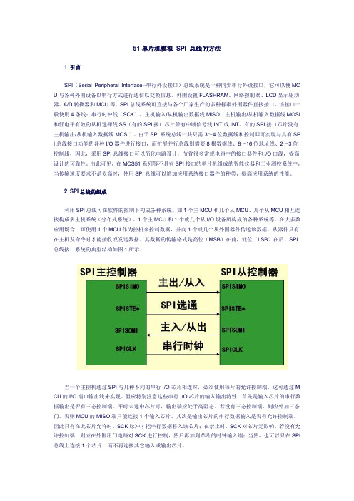
SPI 总线接口系统的典型结构如图1所示。
当一个主控机通过SPI与几种不同的串行I/O芯片相连时,必须使用每片的允许控制端,这可通过M CU的I/O端口输出线来实现。
但应特别注意这些串行I/O芯片的输入输出特性:首先是输入芯片的串行数据输出是否有三态控制端。
- 1、下载文档前请自行甄别文档内容的完整性,平台不提供额外的编辑、内容补充、找答案等附加服务。
- 2、"仅部分预览"的文档,不可在线预览部分如存在完整性等问题,可反馈申请退款(可完整预览的文档不适用该条件!)。
- 3、如文档侵犯您的权益,请联系客服反馈,我们会尽快为您处理(人工客服工作时间:9:00-18:30)。
X25F064/032/016/008SerialFlash™ and Block Lock™ Protection are trademarks of Xicor, Inc.SerialFlash™ Memory With Block Lock TM ProtectionFEATURES•1MHz Clock Rate •SPI Serial Interface •64K/32K/16K/8K Bits—32 Byte Small Sector Program Mode •Low Power CMOS—<1µA Standby Current —<5mA Active Current• 1.8V – 3.6V or 5V “Univolt” Read and Program Power Supply Versions •Block Lock Protection—Protect 1/4, 1/2, or all of E 2PROM Array •Built-in Inadvertent Program Protection—Power-Up/Power-Down protection circuitry —Program Enable Latch —Program Protect Pin •Self-Timed Program Cycle—5ms Program Cycle Time (Typical)•High Reliability—Endurance: 100,000 cycles per byte —Data Retention: 100 Years—ESD protection: 2000V on all pins •8-Lead PDlP Package•8-Lead 150 mil SOIC Packages•32K, 16K, 8K available in 14-Lead TSSOP,64K available in 20-Lead TSSOP DESCRIPTIONThe X25F064/032/016/008 family are 8/16/32/64K-bit CMOS SerialFlash memory, internally organized X 8. They feature a “Univolt” Program and Read voltage,Serial Peripheral Interface (SPI), and software protocol allowing operation on a simple three-wire bus. The bus signals are a clock input (SCK), plus separate data in (SI) and data out (SO) lines. Access to the device is controlled through a chip select (CS ) input, allowing any number of devices to share the same bus.The X25F064/032/016/008 also features two additional inputs that provide the end user with added flexibility. By asserting the HOLD input, the X25F064/032/016/008will ignore transitions on its inputs, thus allowing the host to service higher priority interrupts. The PP input can be used as a hardwire input to the X25F064/032/016/008disabling all program attempts to the status register,thus providing a mechanism for limiting end user capa-bility of altering 0, 1/4, 1/2, or all of the memory.The X25F064/032/016/008 utilizes Xicor’s proprietary flash cell, providing a minimum endurance of 100,000 cycles and a minimum data retention of 100 years.FUNCTIONAL DIAGRAM© Xicor, Inc. 1995, 1996 Patents Pending Characteristics subject to change without notice6685-3.1 8/29/96 T3/C0/D0 SH6685 ILL F01.4SI SOHOLDPPSCK2X25F064/032/016/008Hold (HOLD )HOLD is used in conjunction with the CS pin to select the device. Once the part is selected and a serial sequence is underway, HOLD may be used to pause the serial communication with the controller without resetting the serial sequence. To pause, HOLD must be brought LOW while SCK is LOW. To resume communication,HOLD is brought HIGH, again while SCK is LOW. If the pause feature is not used, HOLD should be held HIGH at all times.PIN NAMES SYMBOL DESCRIPTION CS Chip Select Input SO Serial Output SI Serial InputSCK Serial Clock Input PP Program Protect Input V SS GroundV CC Supply Voltage HOLD Hold Input NCNo Connect6685 PGM T01.1PIN DESCRIPTIONS Serial Output (SO)SO is a push-pull serial data output pin. During a read cycle, data is shifted out on this pin. Data is clocked out by the falling edge of the serial clock.Serial Input (SI)SI is the serial data input pin. All opcodes, byte addresses, and data to be written to the memory are input on this pin. Data is latched by the rising edge of the serial clock.Serial Clock (SCK)The Serial Clock controls the serial bus timing for data input and output. Opcodes, addresses, or data present on the SI pin are latched on the rising edge of the clock input, while data on the SO pin change after the falling edge of the clock input.Chip Select (CS )When CS is HIGH, the X25F064/032/016/008 is deselected and the SO output pin is at high impedance and unless an internal program operation is underway the X25F064/032/016/008 will be in the standby power mode. CS LOW enables the X25F064/032/016/008,placing it in the active power mode. It should be noted that after power-up, a HIGH to LOW transition on CS is required prior to the start of any operation.Program Protect (PP )When PP is LOW and the nonvolatile bit PPEN is “1”,nonvolatile programming of the X25F064/032/016/008status register is disabled, but the part otherwise func-tions normally. When PP is held HIGH, all functions,including nonvolatile programming operate normally.PP going LOW while CS is still LOW will interrupt programming of the X25F064/032/016/008 status regis-ter. If the internal program cycle has already been initiated, PP going LOW will have no effect on program-ming.The PP pin function is blocked when the PPEN bit in the status register is “0”. This allows the user to install the X25F064/032/016/008 into a system with PP pin grounded and still be able to program the status register.The PP pin functions will be enabled when the PPEN bit is set “0”.PIN CONFIGURATION6685 ILL F02.4CS SO PP V SS12348765V CC HOLD SCK SI8-Lead DIP/SOIC14-Lead TSSOP 20-Lead TSSOP CS SO NC NC NC PP V SS1234567V CC HOLD NC NC NC SCK SI141312111098NC CS NC SO NC NC PP V SS NC NC12345678910NC V CC NC HOLD NC NC SCK SI NC NC20191817161514131211X25F064/032/016/008X25F032/016/008X25F064X25F064/032/016/0083formatted as follows:PPEN, BL0, and BL1 are set by the PRSR instruction. PEL and PIP are “read-only” and automatically set by other operations.The Programming-In-Process (PIP) bit indicates whether the X25F064/032/016/008 device is busy with a program operation. When set to a “1”programming is in progress, when set to a “0” no programming is in progress. During programming, all other bits are set to “1”.The Program Enable Latch (PEL) bit indicates the status of the program enable latch. When set to a “1” the latch is set; when set to a “0” the latch is reset.The Block Lock (BL0 and BL1) bits are nonvolatile and allow the user to select one of four levels of protection. The X25F064/032/016/008 device array is divided into four equal segments. One, two, or all four of the seg-ments may be locked. That is, the user may read the segments, but will be unable to alter (program) data within the selected segments. The partitioning is con-trolled as illustrated below.Status Register Bits Array AddressesBL1BL0Locked00None01upper fourth10upper half11All6685 PGM T03.1 Program-Protect EnableThe Program-Protect-Enable bit (PPEN) in the X25F064/032/016/008 status register acts as an enable bit for the PP pin.PRINCIPLES OF OPERATIONThe X25F064/032/016/008 family are SerialFlash Memory designed to interface directly with the synchro-nous serial peripheral interface (SPI) of many popular microcontroller families.The X25F064/032/016/008 family contains an 8-bit instruction register. It is accessed via the SI input, with data being clocked in on the rising SCK. CS must be LOW and the HOLD and PP inputs must be HIGH during the entire operation. The PP input is “Don’t Care” if PPEN is set “0”.Table 1 contains a list of the instructions and their operation codes. All instructions, addresses and data are transferred MSB first.Data input is sampled on the first rising edge of SCK after CS goes LOW. SCK is static, allowing the user to stop the clock and then resume operations. If the clock line is shared with other peripheral devices on the SPI bus, the user can assert the HOLD input to place the X25F064/ 032/016/008 into a “PAUSE” condition. After releasing HOLD, the X25F064/032/016/008 device will resume operation from the point when HOLD was first asserted.Program Enable LatchThe X25F064/032/016/008 device contains a program enable latch. This latch must be SET before a program operation will be completed internally. The PREN instruction will set the latch and the PRDI instruction will reset the latch. This latch is automatically reset on power-up and after the completion of a sector program or status register write cycle.Status RegisterThe RDSR instruction provides access to the status register. The status register may be read at any time, even during a program cycle. The status register is76543210 PPEN X X X BL1BL0PEL PIP6685 PGM T02.2Table 1. Instruction SetInstruction Name Instruction Format*OperationPREN0000 0110Set the Program Enable Latch (Enable Program Operations) PRDI0000 0100Reset the Program Enable Latch (Disable Program Operations) RDSR0000 0101Read Status RegisterPRSR0000 0001Program Status RegisterREAD0000 0011Read from Memory Array beginning at Selected AddressPROGRAM0000 0010Program Memory Array beginning at Selected Address(32 Bytes)6685 PGM T04.2*Instructions are shown MSB in leftmost position. Instructions are transferred MSB first.X25F064/032/016/008Locked Unlocked Status PPEN PP PEL Blocks Blocks Register0X0Locked Locked Locked0X1Locked Programmable Programmable1 LOW0Locked Locked Locked1 LOW1Locked Programmable LockedX HIGH0Locked Locked LockedX HIGH1Locked Programmable Programmable6685 PGM T05.2 The Program Protect (PP) pin and the nonvolatile Program Protect Enable (PPEN) bit in the Status Reg-ister control the programmable hardware write protect feature. Hardware program protection is enabled when PP pin is LOW, and the PPEN bit is “1”. Hardware program protection is disabled when either the PP pin is HIGH or the PPEN bit is “0”. When the chip is hardware program protected, nonvolatile programming of the Sta-tus Register in disabled, including the Block Lock bits and the PPEN bit itself, as well as the Block Lock sections in the memory array. Only the sections of the memory array that are not Block Locked can be pro-grammed.Note:Since the PPEN bit is program protected, it cannot be changed back to a “0”, as long asthe PP pin is held LOW.Clock and Data TimingData input on the SI line is latched on the rising edge of SCK. Data is output on the SO line by the falling edge of SCK.Read SequenceWhen reading from the SerialFlash memory array, CS is first pulled LOW to select the device. The 8-bit READ instruction is transmitted to the X25F064/032/016/008 device, followed by the 16-bit address. After the read opcode and address are sent, the data stored in the memory at the selected address is shifted out on the SO line. The data stored in memory at the next address can be read sequentially by continuing to provide clock pulses. The address is automatically incremented to the next higher address after each byte of data is shifted out. When the highest address is reached the address counter rolls over to address $0000, allowing the read cycle to be continued indefinitely. The read operation is terminated by taking CS HIGH. Refer to the Read SerialFlash Memory Array Operation Sequence illustrated in Figure 1.To read the status register, the CS line is first pulled LOW to select the device followed by the 8-bit instruc-tion. After the read status register opcode is sent, the contents of the status register are shifted out on the SO line. The Read Status Register Sequence is illustrated in Figure 2.Programming SequencePrior to any attempt to program the X25F064/032/016/ 008 device, the program enable latch must first be set by issuing the PREN instruction (See Figure 3). CS is first taken LOW, then the PREN instruction is clocked into the X25F064/032/016/008 device. After all eight bits of the instruction are transmitted, CS must then be taken HIGH. If the user continues the programming operation without taking CS HIGH after issuing the PREN instruc-tion, the programming operation will be ignored.To program the SerialFlash memory array, the user issues the PROGRAM instruction, followed by the ad-dress of the first location in the sector and then the data to be programmed. The data is programmed in a 256-clock operation. CS must go LOW and remain LOW for the duration of the operation. The 32 bytes must reside in the same sector and cannot cross sector boundaries.If the address counter reaches the end of the sector and the clock continues, or if fewer than 32 bytes are clocked in, the contents of the sector cannot be guaranteed.For the program operation to be completed, CS can only be brought HIGH after bit 0 of data byte 32 is clocked in.If it is brought HIGH at any other time the program operation will not be completed. Refer to Figure 4 below for a detailed illustration of the programming sequence and time frames in which CS going HIGH is valid.To program the status register, the PRSR instruction is followed by the data to be programmed. Data bits 0, 1, 4, 5 and 6 must be “0”. This sequence is shown in Figure 5.While the program cycle is in progress, following a status register or memory write sequence, the status register may be read to check the PIP bit. During this time the PIP bit will be HIGH.Hold OperationThe HOLD input should be HIGH (at V IH) under normal operation. If a data transfer is to be interrupted HOLD can be pulled LOW to suspend the transfer until it can be resumed. The only restriction is that the SCK input must be LOW when HOLD is first pulled LOW and SCK must also be LOW when HOLD is released.The HOLD input may be tied HIGH either directly to V CC or tied to V CC through a resistor.4X25F064/032/016/0085Operational NotesThe device powers-up in the following state:•The device is in the low power standby state.• A HIGH to LOW transition on CS is required to enter an active state and receive an instruction.•SO pin is high impedance.•The program enable latch is reset.Data ProtectionThe following circuitry has been included to prevent inadvertent programming:•The program enable latch is reset upon power-up.• A program enable instruction must be issued to set the program enable latch.•CS must come HIGH at the proper clock count in order to start a program cycle.Figure 2. Read Status Register Operation SequenceX25F064/032/016/008Figure 3. Program Enable Latch Sequence6X25F064/032/016/008Figure 4. Programming SequenceFigure 5. Program Status Register Operation Sequence78X25F064/032/016/008*COMMENTStresses above those listed under “Absolute Maximum Ratings” may cause permanent damage to the device.This is a stress rating only and the functional operation of the device at these or any other conditions above those listed in the operational sections of this specification is not implied. Exposure to absolute maximum rating conditions for extended periods may affect device reliability.ABSOLUTE MAXIMUM RATINGS*Temperature Under Bias..................–65°C to +135°C Storage Temperature.......................–65°C to +150°C Voltage on any Pin with Respect to V SS .........–1V to +7V D.C. Output Current .............................................5mA Lead Temperature(Soldering, 10 Seconds).............................300°C D.C. OPERATING CHARACTERISTICS (Over the recommended operating conditions unless otherwise specified.)LimitsSymbolParameterMin.Max.UnitsTest ConditionsI CC V CC Supply Current (Active)5mA SCK = V CC x 0.1/V CC x 0.9 @ 1MHz,SO = Open, CS = V SSI SB1(2)V CC Supply Current (Standby)1µA CS = V CC , V IN = V SS or V CC , V CC = 3.6V I SB2V CC Supply Current (Standby)10µA CS = V CC , V IN = V SS or V CC , V CC = 5V I LI Input Leakage Current 10µA V IN = V SS to V CC I LO Output Leakage Current –110µA V OUT = V SS to V CCV IL (1)Input LOW Voltage V CC x 0.7V CC x 0.3V V IH (1)Input HIGH Voltage V CC + 0.5V V OL1Output LOW Voltage 0.4V I OL = 1.5mA, V CC = 2.7VV OH1Output HIGH Voltage V CC – 0.3V I OH = –0.4mA, V CC = 2.7V V OL2Output LOW Voltage 0.4V I OL = 3mA, V CC = 5V V OH2Output HIGH Voltage V CC – 0.8VI OH = –1.6mA, V CC = 5V6685 PGM T08.4RECOMMENDED OPERATING CONDITIONSTempmercial 0°C +70°C Extended –20°C +85°C Industrial–40°C +85°C6685 PGM T06.2Supply Voltage Limits X25F064/032/016/008 1.8V to 3.6V X25F064/032/016/008–5 4.5V to 5.5V6685 PGM T07.3POWER-UP TIMING Symbol ParameterMin.Max.Units t PUR (3)Power-up to Read Operation 1ms t PUW (3)Power-up to Write Operation5ms6685 PGM T09Notes:(1) V IL min. and V IH max. are for reference only and are not tested.(2) This parameter is periodically sampled and not 100% tested.(3) t PUR and t PUW are the delays required from the time V CC is stable until the specified operation can be initiated. These parameters are periodically sampled and not 100% tested.CAPACITANCE T A = 25°C, f = 1MHz, V CC = 5V.Symbol TestMax.Units Conditions C OUT (2)Output Capacitance (SO)8pF V OUT = 0V C IN (2)Input Capacitance (SCK, SI, CS , WP , HOLD )6pFV IN = 0V6685 PGM T10.1X25F064/032/016/008EQUIVALENT A.C. LOAD CIRCUIT A.C. TEST CONDITIONSData Output TimingSymbol Parameter Min.Max.Unitsf SCK Clock Frequency01MHzt DIS Output Disable Time500ns t V Output Valid from Clock LOW400ns t HO Output Hold Time0ns t RO(4)Output Rise Time300ns t FO(4)Output Fall Time300ns t LZ(4)HOLD HIGH to Output in Low Z100ns t HZ(4)HOLD LOW to Output in High Z100ns6685 PGM T13.2 Notes:(4)This parameter is periodically sampled and not 100% tested.(5)t WC is the time from the rising edge of CS after a valid write sequence has been sent to the end of the self-timed internalnonvolatile program cycle.9X25F064/032/016/008Serial Output TimingSerial Input Timing10Hold TimingPACKAGING INFORMATION3926 FHD F01NOTE:1. ALL DIMENSIONS IN INCHES (IN PARENTHESES IN MILLIMETERS)2. PACKAGE DIMENSIONS EXCLUDE MOLDING FLASHTYP 8-LEAD PLASTIC DUAL IN-LINE PACKAGE TYPE PMAX.PACKAGING INFORMATION8-LEAD PLASTIC SMALL OUTLINE GULL WING P ACKAGE TYPE SNOTE: ALL DIMENSIONS IN INCHES (IN P ARENTHESES IN MILLIMETERS)3926 FHD F22.1PACKAGING INFORMATIONNOTE: ALL DIMENSIONS IN INCHES (IN P ARENTHESES IN MILLIMETERS)14-LEAD PLASTIC, TSSOP PACKAGE TYPE V0° – 83926 FHD F32NOTE: ALL DIMENSIONS IN INCHES (IN P ARENTHESES IN MILLIMETERS)20-LEAD PLASTIC, TSSOP PACKAGE TYPE V0° – 83926 FHD F45PACKAGING INFORMATIONORDERING INFORMATIONLIMITED WARRANTYDevices sold by Xicor, Inc. are covered by the warranty and patent indemnification provisions appearing in its Terms of Sale only. Xicor, Inc. makes no warranty,express, statutory, implied, or by description regarding the information set forth herein or regarding the freedom of the described devices from patent infringement.Xicor, Inc. makes no warranty of merchantability or fitness for any purpose. Xicor, Inc. reserves the right to discontinue production and change specifications and prices at any time and without notice.Xicor, Inc. assumes no responsibility for the use of any circuitry other than circuitry embodied in a Xicor, Inc. product. No other circuits, patents, licenses are implied.U.S. PATENTSXicor products are covered by one or more of the following U.S. Patents: 4,263,664; 4,274,012; 4,300,212; 4,314,265; 4,326,134; 4,393,481; 4,404,475;4,450,402; 4,486,769; 4,488,060; 4,520,461; 4,533,846; 4,599,706; 4,617,652; 4,668,932; 4,752,912; 4,829, 482; 4,874, 967; 4,883, 976. Foreign patents and additional patents pending.LIFE RELATED POLICYIn situations where semiconductor component failure may endanger life, system designers using this product should design the system with appropriate error detection and correction, redundancy and backup features to prevent such an occurrence.Xicor's products are not authorized for use in critical components in life support devices or systems.1.Life support devices or systems are devices or systems which, (a) are intended for surgical implant into the body, or (b) support or sustain life, and whose failure to perform, when properly used in accordance with instructions for use provided in the labeling, can be reasonably expected to result in a significant injury to the user.2.A critical component is any component of a life support device or system whose failure to perform can be reasonably expected to cause the failure of the life support device or system, or to affect its safety or effectiveness.DeviceX25FXXXP T –XV CC RangeBlank = 1.8V to 3.6V 5 = 4.5V to 5.5VTemperature RangeBlank = Commercial = 0°C to +70°C E = Extended = –20°C to +85°C I = Industrial = –40°C to +85°C PackageX25F064X25F032P = 8-Lead Plastic DIP X25F016S = 8-Lead SOIC X25F008V = 20-Lead TSSOPP = 8-Lead Plastic DIP S = 8-Lead SOIC V = 14-Lead TSSOPP = 8-Lead Plastic DIP Blank = 8-Lead SOIC V = 14/20-Lead TSSOP Blank = 1.8V to 3.6V, 0°C to +70°C 5 = 4.5V to 5.5V, 0°C to +70°C I5 = 4.5V to 5.5V, –40°C to +85°CX25FXXXXPart Mark ConventionX25F064X25F032X25F016X25F008。
