mlc104IP Plus系列 带IP Link的MLC-MediaLink控制器
Mellanox SX6710G 高性能、低延迟 56Gb s FDR InfiniBand 到 4

©2018 Mellanox Technologies. All rights reserved.†For illustration only. Actual products may vary.The SX6710G is a high-performance, low-latency 56Gb/s FDR InfiniBand to 40Gb/s Ethernet gateway.SCALING-OUT DATA CENTERS WITH INFINIBAND TO ETHERNET GATEWAYFaster servers based on PCIe 3.0, combined with high-performance storage and applications that use increasingly complex computations, are causing data bandwidth requirements to spiral upward. As servers are deployed with next generation processors, High-Performance Computing (HPC) environments and Enterprise Data Centers (EDC) will need every last bit of bandwidth delivered with Mellanox’s FDR InfiniBand to 40GbE high-speed smart gateways.VIRTUAL PROTOCOL INTERCONNECT ® (VPI)Virtual Protocol Interconnect (VPI) flexibility enables any standard networking, clustering, storage and management protocol to seamlessly operate over any converged network leveraging a consolidated software stack. VPI simplifies I/O system design and makes it easier for IT managers to deploy infrastructure that meets the challenges of a dynamic data center.With its high bandwidth, low latency and reduced overhead, InfiniBand is the ideal choice for speeding application performance while simultaneously consolidating network and I/O infrastructure. Combining InfiniBand and Ethernet into a single solution provides an ideal rack backbone for next generation data centers.SUSTAINED NETWORK PERFORMANCEBuilt with Mellanox’s SwitchX ®-2-based switches, the InfiniBand to Ethernet gateway software license or system, provides full port flexibility to choose between 56Gb/s InfiniBand to either 10, 40 and 56Gb/s Ethernet with low 430ns latency.SX6710G, when combined with Mellanox’s ConnectX ®host adapter family, delivers cost savings byintegrating two networks on a single wire. Consolidating multiple networks on a single wire delivers both CAPEX and OPEX savings. OPEX savings are provided by reducing cabling complexity, reducing switch and server infrastructure and delivering a consistent and easy to use management software.MANAGEMENTSX6710G MLNX-OS ® software delivers complete chassis management, to manage the firmware, power supplies, fans, ports and other interfaces. SX6710G can also be coupled with Mellanox’s Unified Fabric Manager (UFM ®) software for managing scale-out computing environments. UFM enables data center operators to efficiently provision, monitor and operate the modern data center fabric.36-port Non-blocking Managed 56Gb/s InfiniBand to 40GbE Ethernet GatewaySX6710G InfiniBand to Ethernet GatewayPRODUCT BRIEFGATEWAY SYSTEM †350 Oakmead Parkway, Suite 100, Sunnyvale, CA 94085Tel: 408-970-3400 • Fax: © Copyright 2018. Mellanox Technologies. All rights reserved.Mellanox, Mellanox logo, ConnectX, SwitchX, MLNX-OS, Virtual Protocol Interconnect and UFM are registered trademarks of Mellanox Technologies, Ltd. All other trademarks are property of their respective owners.Mellanox SX6710G InfiniBand to Ethernet Gatewaypage 2Mellanox SX6710G –19’’ rack mountable chassis, 1Uwith redundant power supplies and fan units –36 QSFP non-blocking ports with aggregate data throughput up to 4.032Tb/s (FDR) –InfiniBand port-to-port latency 200ns –Ethernet port-to-port latency 230ns InfiniBand Switch Specifications –Compliant with IBTA 1.21 and 1.3 –9 virtual lanes: 8 data + 1 management–256 to 4Kbyte MTU–48K L2 forwarding entriesEthernet Switch Specifications –48K L2 forwarding entries –Static MAC –802.1w Rapid Spanning Tree Protocol–802.3ad Link Aggregation/LACP–802.3x Flow control–802.1Qbb Priority Flow Control (PFC) –802.1Qaz Enhanced Transmission Selection –802.1AB LLDP –VLAN 802.1Q (4K) –IGMP v1,v2, Snooping –Access Control Lists (L2-L4) –Jumbo Frames (9216 Bytes) –sFlow –Port Mirroring Management –Dual 100/1000Mb/s Ethernet ports–RS232 port over DB9–USB port–DHCP –SNMP v1,2,3 –JSON & CLI, Enhanced WebUI –ZTP –Dual software image–SYSLOGConnectors and Cabling –QSFP+ connectors –Passive copper or active fiber cables–Optical modulesIndicators–Per port status LED Link, Activity–System status LEDs: System, fans, power supplies –Port Error LED –Unit ID LEDPhysical Characteristics–Dimensions:1.72’’H x 16.84’’W x 27’’D –Weight: 19.4 lb (8.8 kg)Power Supply–Dual redundant slots –Hot plug operation –Input range:100-127VAC, 200-240VAC –Frequency:50-60Hz, single phase ACCooling–Front-to-rear or rear-to-front coolingoption –Hot-swappable fan unit Power Consumption Typical power consumption:–Passive cable - 130W –Active cable - 235WFEATURESSafety–CB –cTUVus –CE –CUEMC (Emissions)–CE –FCC –VCCI –ICES –RCMOperating Conditions–Operating 0ºC to 45ºC–Non-Operating -40ºC to 70ºC –Humidity: Operating 5% to 95% –Altitude: Operating -60m to 3200mAcoustic–ISO 7779 –ETS 300 753Others–RoHS-6 compliant –Rack-mountable, 1U –1-year warrantyCOMPLIANCETable 1 - Part Numbers and Descriptions060064PB Rev 1.1* This section describes hardware features and capabilities. Please refer to the driver and firmware release notes for feature availability.。
Dell M系列刀片式服务器
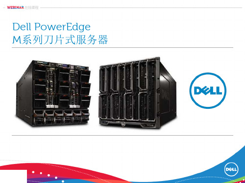
戴尔Force10 MXL 10/40GbE刀片式交换机
高性能且功能全面的1/10/40GbE第2层和第3层交换机刀片
戴尔Force10 MXL 10/40GbE刀片式交换机
内部服务器连接 端口 最多32个GbE/10GbE - 2x40GbE固定端口 - 两个选配Flex I/O模块 40GbE端口 FTOS
Flex I/O
• 4端口SFP+模块 – – 1GbE和10GbE端口 10GbE光纤和DAC铜线 Twin-ax
外部端口
堆叠 操作系统
• 4端口10GBASE-T模块
–
–
比M8024-k多2倍
1GbE和10GbE端口
可靠且可扩展的I/O性能、 低延迟和高带宽 支持本地40GbE端口
• 2端口QSFP+模块
iDRAC 和 vFlash 远程管理和嵌入式 的虚拟化管理程序
网络架构连接器 最多支持两个处理器 易于使用的手柄
• • • • 最多12个千兆以太网端口 最多6个万兆以太网端口 最多4个 FC8 光纤通道 最多4 个QDR InfiniBand
(支持两个Mezz插槽)
最多24个 DIMM内存插槽 (M710HD)
• 板载网卡(LOM)
• Dell的优选网络适配器是提供灵活的网络选择给客户, 业界第一个提供此功能的 厂商, 模块化的设计更方便升级和变更.
• 支持的网卡
• M620
• • • 一个 2x10GbE Broadcom, Intel 或者 Qlogic CNA 2个 2x10GbE Broadcom, Intel 或者 Qlogic CNA 2个Broadcom 2x1GbE 或者 2个 2x10GbE CNA
Xtreme 104 900 MHz和2.4 GHz无线模组PC 104接口用户手册说明书

Xtreme/104 Radio Modems PC/104 Card Manual Xtreme/104 900 MHz and 2.4 GHz Radio ModemsPC/104 Interface User’s ManualContact Information:Connect Tech Inc.42 Arrow RoadGuelph, Ontario, Canada N1K 1S6Tel:519-836-1291 (International)800-426-8979 (Canada & USA)Fax: 519-836-4878Email:********************************************Web: CTIM-00032 Revision 0.01 March, 2007Xtreme/104 Radio Modem, Connect Tech Inc.One Year WarrantyConnect Tech Inc. provides a One-Year Warranty for all Xtreme/104 Radio Modem productsbuilt with Cirronet modules. Should this product, in Connect Tech Inc.'s opinion, fail to be ingood working order during the warranty period, Connect Tech Inc. will, at its option, repair orreplace this product at no charge, provided that the product has not been subjected to abuse,misuse, accident, disaster or non Connect Tech Inc. authorized modification or repair.You may obtain warranty service by delivering this product to an authorized Connect Tech Inc.business partner or to Connect Tech Inc. along with proof of purchase. Product returned toConnect Tech Inc. must be pre-authorized by Connect Tech Inc. with an RMA (Return MaterialAuthorization) number marked on the outside of the package and sent prepaid, insured andpackaged for safe shipment. Connect Tech Inc. will return this product by prepaid groundshipment service.Should the product prove to be irreparable, Connect Tech Inc. reserves the right to substitute anequivalent product if available.The above warranty is the only warranty authorized by Connect Tech Inc. for the Xtreme/104Radio Modems. Under no circumstances will Connect Tech Inc. be liable in any way for anydamages, including any lost profits, lost savings or other incidental or consequential damagesarising out of the use of, or inability to use, such product.Copyright NoticeThe information contained in this document is subject to change without notice. Connect TechInc. shall not be liable for errors contained herein or for incidental consequential damages inconnection with the furnishing, performance, or use of this material. This document containsproprietary information that is protected by copyright. All rights are reserved. No part of thisdocument may be photocopied, reproduced, or translated to another language without the priorwritten consent of Connect Tech, Inc.Copyright © 2007 by Connect Tech, Inc.Trademark AcknowledgmentConnect Tech Inc. acknowledges all trademarks, registered trademarks and/or copyrightsreferred to in this document as the property of their respective owners.Not listing all possible trademarks or copyright acknowledgments does not constitute a lack ofacknowledgment to the rightful owners of the trademarks and copyrights mentioned in thisdocument.2 Revision 0.01Xtreme/104 Radio Modem, Connect Tech Inc.Table of ContentsOne Year Warranty (2)Copyright Notice (2)Trademark Acknowledgment (2)Table of Contents (3)List of Figures (3)List of Tables (3)Customer Support Overview (4)Customer Support Overview (4)Contact Information (4)Introduction (5)Features (5)Radio Modem Modules (5)Xtreme/104 Base Card (5)Figure 1: Xtreme/104 Radio Modem Jumper Locations (6)Hardware Installation (6)Installing the PC/104 Radio Modem into your PC/104 Stack (6)Hardware Configuration (7)Memory Address and Interrupts Selection (7)I/O Address (7)IRQ Selection (8)IRQ Mode (8)Indicator LEDs (9)ACQ (DCD) (9)WAK (DTR) (9)Optional External LEDs (9)Operational Setup (10)Errata (11)List of FiguresFigure 1: Xtreme/104 Radio Modem Jumper Locations (6)List of TablesTable 1: Jumper J2-2 to J2-8 Functions (7)Table 2: J2 Jumpering Examples (8)Revision 0.01 3Xtreme/104 Radio Modem, Connect Tech Inc. Customer Support OverviewIf you experience difficulties after reading the manual and/or using the product, contact theConnect Tech reseller from which you purchased the product. In most cases the reseller can helpyou with product installation and difficulties.In the event that the reseller is unable to resolve your problem, our highly qualified support staffcan assist you. Our support section is available 24 hours a day, 7 days a week on our website at:/sub/support/support.asp. See the contact information section below formore information on how to contact us directly. Our technical support is always free. Contact InformationWe offer three ways for you to contact us:Email/InternetYou may contact us through the Internet. Our email and URL addresses on the Internet are:********************************************Note:Please go to the Download Zone or the Knowledge Database inthe Support Center on the Connect Tech website for productmanuals, installation guides, device driver software andtechnical tips.Submit your technical support questions to our customersupport engineers via the Support Center on the Connect Techwebsite.Telephone/FacsimileTechnical Support representatives are ready to answer your call Monday through Friday, from8:30 a.m. to 5:00 p.m. Eastern Standard Time. Our numbers for calls are:Telephone: 800-426-8979 (North America only)Telephone: 519-836-1291 (Live assistance available 8:30 a.m. to 5:00 p.m. EST, Monday toFriday)Facsimile: 519-836-4878 (on-line 24 hours)Mail/CourierYou may contact us by letter at:Connect Tech Inc.Technical Support42 Arrow RoadGuelph, OntarioCanada N1K 1S64 Revision 0.01Xtreme/104 Radio Modem, Connect Tech Inc.IntroductionConnect Tech’s PC/104 Radio Modems, available with Cirronet’s WIT910, WIT2450 orWIT2410 roaming transceiver modules, offer a conveinient, reliable method to introducewireless communications into your PC/104 application.Fully PC/104 2.5 compliant, this card installs into an available PC/104 position in your stack tocommunicate up to 20 miles away (“line of sight” only), depending on model and antennaconfiguration.FeaturesRadio Modem Modules•Frequency hopping spread spectrum technology•900 MHz or 2.4 GHz , incorporating Cirronet’s WIT910, WIT2410 or WIT2450 frequency hopping transceiver modules•Radio modem operating ranges of up to 20 miles (900 MHz model, with appropriate antennas in a “line of sight” implementation)•Low power consumption (can be powered via the PC/104 bus)•Store and forward repeating while operating as a node (WIT910)•License-free operation•Immunity to jamming and multipath fading, even in noisy environments•Available with roaming capability (2.4 GHz)•FCC certified•Data speeds between 86.4 Kbps (900 MHz) and 230.4 Kbps (2.4 GHz)•Point-to-point and point-to-multipoint network deployments•Operating temperature range of 0˚C to 70˚CXtreme/104 Base Card•Jumper selectable I/O addresses and interrupts•I/O address ranges from 0x000 to 0x7F0 (jumper selectable)•RTS/CTS hardware flow control•Jumper selectable IRQ interrupts 3, 4, 6, 7, 9, 10, 11, 12, 14, 15•Requires no additional drivers, appears as COM port to your operating systemRevision 0.01 5Xtreme/104 Radio Modem, Connect Tech Inc.6 Revision 0.01Figure 1: Xtreme/104 Radio Modem Jumper LocationsHardware InstallationInstalling the PC/104 Radio Modem into your PC/104 StackBefore you place your Xtreme/104 Radio Modem into your PC/104 stack, take a minute to ensure that your package includes the required components that should have shipped with your PC/104 Radio Modem.• One unit• One CD containing software and documentation • One cable (optional) • One antenna (optional)If any of these components is missing, contact Connect Tech (see Contact Details) or your reseller.This card can be installed into any PC/104 stack and is fully PC/104 2.5 compliant.Xtreme/104 Radio Modem, Connect Tech Inc.Revision 0.01 7Hardware ConfigurationMemory Address and Interrupts SelectionI/O AddressJ2 positions 2 through 8:Jumper block J2, positions 2 through 8, define the I/O Base Address setting for the UART. The board decodes 16 consecutive I/O addresses starting at the Base address. Each of the jumper positions corresponds to one bit of the I/O Address. If a jumper is installed (“On”), then the corresponding bit equals 1, otherwise that bit equals zero. (Please see Figure 1) for jumper locations.)Table 1: Jumper J2-2 to J2-8 FunctionsJ2 position Corresponding I/O Address Bit 2 I/O address bit 4 3 I/O address bit 5 4 I/O address bit 6 5 I/O address bit 7 6 I/O address bit 8 7 I/O address bit 9 8I/O address bit 10J2 position 1:Position J2-1 enables the control of the CFG (Configuration) signal on the Radio Modem. When the CFG signal is asserted, the Radio Modem is placed into its Configuration Mode. This is an alternate method of placing the Radio Modem in this state.When this position is not jumpered (“Off”):• The control of the Radio Modem CFG signal is disabled.When this position is jumpered (“On”):● The control of the Radio Modem CFG signal is enabled, and the operation of the CFGsignal is controlled by I/O writes to I/O Base Address + 0x08 [See Note 1 below].o Writing 0x00 disables the CFG mode, writing 0x01 enables the CFG mode. Onlybit-0 of the written byte has significance, all other bits are ignored. (The CFG mode is Disabled at power-up).Notes:[1] See Errata.[2] The lower 3 bits of the I/O address (A2, A1, A0), access theRegisters of the UART.[3] The Base I/O Address is always on a boundary of 16, [4] The total I/O setting range possible is 0x000 to 0x7F0. .[5] Settings below 0x100 should be used with caution, since theremay be conflicts with system devices.[6] Some systems may not support an I/O Base setting greaterthan 0x3F8.Xtreme/104 Radio Modem, Connect Tech Inc.8 Revision 0.01Table 2: J2 Jumpering ExamplesJ2 PositionsUART I/O AddressCFG I/O Address8 7 6 5 4 3 2 1Off On On Off Off Off Off Off 0x300 (01100000uuu) ---Off On On Off Off Off Off On 0x300 (01100000uuu) 0x308 (01100001xxx) [Note 1]Off On On Off Off Off On Off 0x310 (01100010uuu) ---Off On On Off Off Off On On 0x310 (01100010uuu) 0x318 (01100011xxx) [Note 1] On Off On Off On On Off On 0x560 (10101100uuu) 0x568 (10101101xxx) [Note 1]Off On On On On On On Off 0x3F0 (01111110uuu) ---Off On On On On On On On 0x3F0 (01111110uuu)0x3F8 (01111111xxx) [Note 1](Please see Figure 1 for jumper locations)Notes:[1] See Errata sectionIRQ SelectionThe IRQ number selection is controlled by jumper block J1. Jumpers 1 through 10 correspond to the IRQ numbers listed in Table 2 below. Only one jumper should be installed.Table 3: IRQ SelectionJ1 Position IRQ# 1 3 2 4 3 6 4 7 5 9 6 10 7 11 8 12 9 14 1015IRQ ModeJ2-9 (when jumpered or “On”) enables the IRQ to be shared with other cards/devices in the system.J2-10 (when jumpered or “On”) provides a 1K pull-down resistor on the selected IRQ signal. This is used in conjunction with the Shared IRQ mode. Only one 1K resistor is allowed in the system per Shared IRQ. Only one card in the system should provide this pull-down.Note:The IRQ Sharing mechanism is implemented as described in the PC/104 Bus Specification V2.5.(Please see Figure 1 for jumper locations.)Xtreme/104 Radio Modem, Connect Tech Inc.Revision 0.01 9Indicator LEDsThere are two red LEDs located on the PC/104 board. They serve to indicate whether the Xtreme/104 Radio Modem has aquired a lock (ACQ) and whether it is awake (WAK).ACQ (DCD)This LED indicates that the Xtreme/104 Radio Modem has acquired (ACQ) a lock with the hopping pattern. This applies to modems that are configured to be Remotes. A Base RadioModem would have this LED on at all times. The signal which drives this LED is also the DCD input on the serial port. When DCD is on, the Radio Modem has acquired the lock.WAK (DTR)This LED indicates that the Xtreme/104 Radio Modem is awake (WAK), or not sleeping. The serial port DTR signal is driving both this LED and the Sleep Signal of the Radio Modem. When DTR is on, the Radio Modem is awake.Optional External LEDsThe Xtreme/104 Radio Modem includes the option to connect the LED drivers to LEDs located external to board. Connector P4 provides this ability. (See Figure 2). The pinout for this connector is provided below.Table 4: Connector P4 Pinout for External LEDs PinFunction 1 ACQ 2 Gnd 3 WAK 4GndFigure 2: P4 Connector Option for External LEDsXtreme/104 Radio Modem, Connect Tech Inc.10 Revision 0.01Operational SetupA minimum operational setup for the Xtreme/104 Radio Modem card must include an antenna connected to the Radio Modem module at each end of the communications link.The following illustration demonstrates a typical lab or prototype setup using two possiblecable/antenna styles (only one antenna is needed at each end). The mounting surface for the antenna end of the patch cable could be the housing of the PC/104 stack or some other mounting surface. A metallic surface is preferred, but not necessary. In most situations a vertical orientation of the antenna works best, but this can be influenced by the environmental factors listed below.A field setup or a final application setup may vary greatly from application to application. Environmental factors play a big role in the effective deployment of wireless communication equipment. The following items need to be considered.• Desired range• Obstacles between the stations (hills, buildings, trees, etc) • RF power output settings of the modules • Attenuation of the interconnecting RF cables • RF gain of the antennas• Prevailing weather conditions• Multi-path (multiple RF pathways) effectsIn many circumstances experiments need to be conducted on the field setup to determine the effectiveness of the setup.Connect Tech’s partner, Cirronet, can offer application assistance with the choice of RF cabling and antennas and with the environmental considerations for a particular field installation. Contact Cirronet to ensure your unique application requirements are met.Xtreme/104 Radio Modem, Connect Tech Inc.ErrataCFG Mode OperationProblem DescriptionRevision “B” boards exhibit a problem when using the Radio Modem CFG Signal control feature (enabled with J2-position-1). When using an I/O address of Base+0x08, the data byte written also gets transmitted by the UART.Solution:The issue will be resolved in revision “C” of the board.Resolution:Instead of using an I/O address of Base+0x08, use Base+0x0F. The data value used will also bewritten into the UART Scratch-Pad register, but this does not affect the normal operation of theUART.Revision 0.01 11。
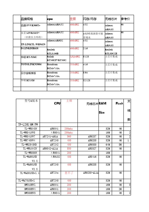
无线路由器CPU闪存内存芯片列表
TR-966D
RealtekRTL8305SC
TR-965DA
EN29LV160AB闪存2MB
S29AL908D70TE102不明芯片
TL-R480T
TL-R4000
TL-R480T÷
TL-R488T
TL-R4000+
TL-SG3109
TL-SG3216
TL-SG3224
TL-SG3248
TL-SL3428
TL-SL3452
TL-SG2109WEB
IntelFWIXP420BB(CPU)+MarVell88E6063(Switch)
Marvell88E6092(MAC)+88E1111(PHY)+88E6218(CPU)
Marvell88E6092(MAC)+88E1111(PHY)+88E6218(CPU)
Marvell88E6182+88E6092(MAC)+88E1111(PHY)+88E6218(CPU)
Marvell88E6182+88E6092(MAC)+88E1111(PHY)+88E6218(CPU)
品牌规格
cpu
主频
闪存/内存
无线芯片
参考价
迅捷FVVR300T+
AtherosAR9132
400MHZ
4/32
Atheros
AR9103
90
水星MWR300T+
(旧款长方形的)
AtherosAR9132
400MHZ
4/32Vl版新款可能有缩水
Atheros
AR9103
90
Vigor2920 系

Vigor2920 系列雙WAN安全防護路由器快速安裝手冊版本: 1.0韌體版本: V3.3.3.1日期: 19/07/2010因手冊更新無法及時通知用戶,請隨時連上居易網站,取得最新的手冊內容。
版權資訊版權聲明© 2010版權所有,翻印必究。
此出版物所包含資訊受版權保護。
未經版權所有人書面許可,不得對其進行拷貝、傳播、轉錄、摘錄、儲存到檢索系統或轉譯成其他語言。
交貨以及其他詳細資料的範圍若有變化,恕不預先通知。
商標本手冊內容使用以下商標:z Microsoft為微軟公司註冊商標z Windows視窗系列,包括Windows 95, 98, Me, NT, 2000, XP 以及其Explorer均屬微軟公司商標z Apple以及Mac OS均屬蘋果電腦公司的註冊商標z其他產品則為各自生產廠商之註冊商標安全說明和保障安全說明z在設置前請先閱讀安裝說明。
z由於路由器是複雜的電子產品,請勿自行拆除或是維修本產品。
z請勿自行打開或修復路由器。
z請勿把路由器置於潮濕的環境中,例如浴室。
z請將本產品放置在足以遮風避雨之處,適合溫度在攝氏5度到40度之間。
z請勿將本產品暴露在陽光或是其他熱源下,否則外殼以及零件可能遭到破壞。
z請勿將LAN網線置於戶外,以防電擊危險。
z請將本產品放置在小孩無法觸及之處。
z若您想棄置本產品時,請遵守當地的保護環境的法律法規。
保固自使用者購買日起二年內為保固期限,請將您的購買收據保存二年,因為它可以證明您的購買日期。
當本產品發生故障乃導因於製作及(或)零件上的錯誤,只要使用者在保固期間內出示購買證明,居易科技將採取可使產品恢復正常之修理或更換有瑕疵的產品(或零件),且不收取任何費用。
居易科技可自行決定使用全新的或是同等價值且功能相當的再製產品。
下列狀況不在本產品的保固範圍內:(1)若產品遭修改、錯誤(不當)使用、不可抗力之外力損害,或不正常的使用,而發生的故障;(2) 隨附軟體或是其他供應商提供的授權軟體;(3) 未嚴重影響產品堪用性的瑕疵。
杭州瑞盟科技有限公司MS90C104 30bit平板显示器LVDS信号接收器说明书
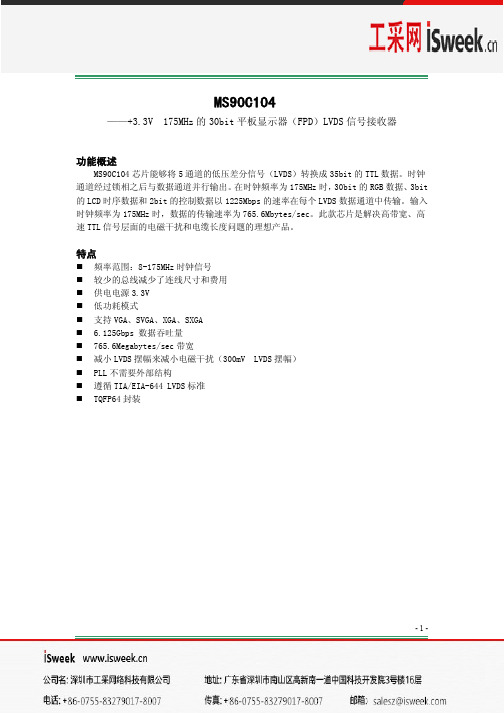
2013.08.12
共9页 第6页
图 4.锁相环设置时间
MS90C104
图 5.接收器状态
Vdiff=(RxIN+)-(RxIN-),……(RxCLKIN+)-(RxCLKIN-)
图 6.并行 TTL 输出数据与 LVDS 输入数据匹配关系
Previous Cycle
Next Cycle
RCLK RL4
1.4W
电学特性
符号 VIH VIL VOH
VOL
IIN IOS
参数 输入高电平 输入低电平 输出高电平
输出低电平
输入电流 输出短路电流
条件
Min
2.0
GND
IOH = -4mA(data) 2.4 IOH = -8mA(clock) IOL = 4mA(data) IOL = 8mA(clock)
-3-
版本号:1.2
2013.08.12
共9页 第3页
MS90C104
推荐工作条件
电源电压(VCC) CMOS/TTL 输入电压 CMOS/TTL 输出电压 LVDS 接收输入电压 结点温度 温度范围 瞬间耐温(焊接,4 秒) 最大功耗(25℃) MS90C104
-0.3V - 4.0V -0.3V - (VCC+0.3V) -0.3V - (VCC+0.3V) -0.3V - (VCC+0.3V) +150℃ -40℃ - 100℃ +260℃
RX0/7/14/21/28
RX1/8/15/22/29
RX2/9/16/23/30 RX3/10/17/24/31 RX4/11/18/25/32 RX5/12/19/26/33 RX6/13/20/27/34
威林视讯科技有限公司产品手册说明书

服务热线:400-150-1816电话*************传真*************地址:北京市昌平区创新路27号昌平科技园区3号5层网址:北京威林视讯科技有限公司VLINC专业视听显控产品手册专业音视频产品与解决方案提供商2022北京威林视讯科技有限公司COMPANY PROFILE公司简介威林的愿景威林的使命威林的核心价值观威林视讯是专注于显示控制一体化解决方案的科技企业,经过多年发展,已经成长为国内显控领域的知名品牌,拥有多项独立自主的知识产权。
自成立以来,威林视讯连续推出多个创新产品,包括纯硬件图像处理器,到图像综合管理平台,从分布式处理器到可视化分布式系统,从46寸液晶拼墙到70寸液晶拼墙,从高清到8K 系统整体解决方案,威林视讯的每一次创新都引导着行业的发展和进步,威林视讯提出的所见即所得,所得即可操作的理念,已经成为显控系统的行业标准。
威林视讯有拥有强大的研发实力和方案设计服务能力,核心团队均具备10年以上的行业经验,与北京大学,北京交通大学等多所高校建立产学研合作关系,在掌握图像算法,具备产品设计能力的基础上,对于客户的订制化需求能够快速响应,从研发到制造,从设计到施工,建立了一整套的客户服务体系。
威林视讯在北京,上海,深圳,广州,南京,成都,南昌,乌鲁木齐等国内主要城市均设有分支机构,具备国内省会级城市的快速响应能力。
威林视讯的团队成功完成多个典型案例,包括北京新机场,北京公安局合成作战指挥中心,天津市委宣传部,国家气象局,火箭军某基地,上海联通,广州移动,酒泉卫星发射基地,滴滴出行等标志性项目,均为所在领域的标杆项目。
共同成长作为一个发展中的公司,威林愿意帮助客户成长,努力给客户提供技术培训,商务支持等各种支持,希望客户在竞争中取胜,威林的体系对客户保持开放,愿意帮助客户建立认证体系和获得各种知识产权。
同样,威林也希望能够跟员工一起成长,公司鼓励员工参加各种学历或者非学历教育并承担部分学费,公司内部也会不断建设良好的分享,培训和晋升的体系,希望能够鼓励每一位员工都能发挥自己最大的价值。
云桌面参数

★5、桌面源:支持物理机完整克隆虚拟机,பைடு நூலகம்接克隆虚拟机等多种桌面源类型。(提供原厂盖章的截图证明)
6、链接克隆桌面:不使用任何组件的条件下,支持链接克隆桌面。
7、云桌面超时控制:可设定超时时间,一旦设定时间内没有操作,桌面会自动断开,并进行关机或挂起操作。
★15、原厂商虚拟化产品要求入围中央政府采购目录,提供截图证明及在线查询验证地址并原厂盖章;
★16、要求与服务器虚拟化、云桌面软件及云平台管理软件同一品牌。
用户
60
750
5
云终端
★1、处理器:x86架构CPU≥1.8GHz双核;
★2、操作系统:采用安全稳定的linux操作系统;
3、内存:≥2G DDR3;
13、提供服务器虚拟化产品的登记证书复印件,原厂商及投标商盖章;
★14、产品安全认证:为了保证云桌面的安全性,其虚拟化产品需要提供专业信息安全测评中心报告及中国信息安全认证中心IT产品信息安全认证获证证书复印件,原厂商及投标商盖章,并提供在线查询验证地址;
★15、要求与服务器虚拟化、云桌面软件及云平台管理软件同一品牌。
★3、采用分布式RAID和缓存镜像,可确保在发生磁盘、主机或网络故障时不丢失数据。
★4、在为每个桌面虚拟机设置存储策略时,可以指定虚拟机能够容忍集群中多少个主机、网络或磁盘发生故障。
★5、通过向现有主机添加磁盘(纵向扩展)或向集群添加新主机(横向扩展),可以无中断地轻松扩大数据存储的容量,并可以实现集群教学环境动态迁移。
6、支持与HA、DRS、FT、存储迁移等核心服务器虚拟化功能全面集成。
7、支持与桌面虚拟化平台进行互操作,进而为虚拟桌面环境提供快速的存储。
NVIDIA Mellanox Quantum HDR 200G InfiniBand 交换机芯片数
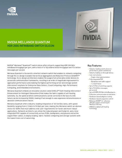
NVIDIA MELLANOX QUANTUM HDR 200G INFINIBAND SWITCH SILICONNVIDIA® Mellanox® Quantum™ switch silicon offers 40 ports supporting HDR 200 Gb/s InfiniBand throughput per port, with a total of 16 Tb/s bidirectional throughput and 15.6 billion messages per second.Mellanox Quantum is the world’s smartest network switch that enables in-network computing through the co-design Scalable Hierarchical Aggregation and Reduction Protocol (SHARP)™ technology. Its co-design architecture enables the usage of all active data center devices to accelerate communication frameworks, resulting in an order of magnitude improvement in application performance and enabling the highest performing server and storage system interconnect solutions for Enterprise Data Centers, Cloud Computing, High-Performance Computing, and Embedded environments.Mellanox Quantum embeds an innovative solution called SHIELD™ (Self-Healing Interconnect Enhancement for Intelligent Datacenters) that makes the fabric capable of self-healing autonomy. So, the speed at which communications can be corrected in the face of a link failure can be increased by 5000X, making it fast enough to save expensive retransmissions or absolute communications failure.Mellanox Quantum offers industry-leading integration of 160 SerDes lanes, with speed flexibility ranging from 2.5 Gb/s to 50 Gb/s per lane, making this Mellanox switch an obvious choice for OEMs that must address end-user requirements for faster and more robust applications. Network architects can utilize the reduced power and footprint, and a fully integrated PHY capable of connectivity across PCBs, backplanes, and passive and active copper/fiber cables, to deploy leading, fabric-flexible computing and storage systems with the lowest total cost of ownership.Key Features>Industry-leading switch silicon in performance, power and density>Industry-leading cut-through latency >Low-cost solution>Single-chip implementation>Fully integrated PHY>Backplane and cable support>1, 2 and 4 lanes>Up to 16 Tb/s of switching capacity>Up to 15.6 billion messagesper second>Up to 40 HDR 200 Gb/s InfiniBand ports >Collective communication acceleration >Hardware-based adaptive routing>Hardware-based congestion control >Mellanox SHARP™v2 collective offloads support streaming for Machine Learning>SHIELD-enabled self-healing technologyINFINIBAND INTERCONNECTMellanox Quantum InfiniBand devices enable industry standard networking, clustering, storage, and management protocols to seamlessly operate over a single “one-wire” converged network. Combined with the Mellanox ConnectX® family of adapters, on-the-fly fabric repurposing can be enabled for Cloud, Web 2.0, EDC and Embedded environments providing “future proofing” of fabrics independent of protocol. Mellanox Quantum enables IT managers to program and centralize their server and storage interconnect management and dramatically reduce their operations expenses by completely virtualizing their data center network.COLLECTIVE COMMUNICATION ACCELERATIONCollective communication describes communication patterns in which all members of a group of communication endpoints participate. Collective communications are commonly used in HPC protocols such as MPI and SHMEM. The Mellanox Quantum switch improves the performance of selected collective operations by processing the data as it traverses the network, eliminating the need to send data multiple times between endpoints.Mellanox Quantum also supports the aggregation of large data vectors at wire speed to enable MPI large vector reduction operations, which are crucial for machine learning applications.TELEMETRYVisibility is a critical component of an efficient network. Capturing what a network is‘thinking’ or ‘doing’ is the basis for true network automation and analytics. In particular, today’s HPC and cloud networks require fine-grained visibility into:>Network state in real-time>Dynamic workloads in virtualized and containerized environments>Advanced monitoring and instrumentation for troubleshootingMellanox Quantum is designed for maximum visibility using such features as mirroring, sFlow, congestion based mirroring, and histograms.SWITCH PRODUCT DEVELOPMENTThe Mellanox Quantum Evaluation Board (EVB) and Software Development Kit (SDK)are available to accelerate an OEM’s time to market and for running benchmark tests. These rack-mountable evaluation systems are equipped with QSFP56 interfaces for verifying InfiniBand functionality. In addition, SMA connectors are available for SerDes characterization. The Mellanox Quantum SDK provides customers the flexibility to implement InfiniBand connectivity using a single switch device.The SDK includes a robust and portable device driver with two levels of APIs, so developers can choose their level of integration. A minimal set of code is implemented in the kernelto allow for easy porting to various CPU architectures and operating systems, such asx86 and PowerPC architectures utilizing the Linux operating system. Within the SDK, the device driver and API libraries are written in standard ANSI “C” language for easy porting to additional processor architectures and operating systems. The same SDK supportsthe Mellanox SwitchX®-2, Switch-IB®, Switch-IB 2, Mellanox Spectrum®, and Mellanox Quantum switch devices. CompatibilityCPU>PowerPC, Intel x86, AMD x86, MIPS PCI Express Interface>PCIe 3.0, 2.0, and 1.1 compliant>2.5 GT/s, 5 GT/s or 8 GT/s x4link rateConnectivity>Interoperability with InfiniBand adapters and switches>Passive copper cables, fiber optics, PCB or backplanes Management & Tools>Support for Mellanox and IBTA compliant Subnet Managers (SM) >Diagnostic and debug tools>Fabric Collective Accelerator (FCA) software libraryORDERING INFORMATIONCONFIGURATIONSMellanox Quantum allows OEMs to deliver: >40-port 1U HDR 200 Gb/s InfiniBand switch >80-port 1U HDR100 100 Gb/s InfiniBand switch>Modular chassis switch with up to 800 HDR InfiniBand ports >Modular chassis switch with up to 1600 HDR100 InfiniBand portsNVIDIA MELLANOX ADVANTAGENVIDIA Mellanox is the leading supplier of industry standard InfiniBand and Ethernet network adapter silicon and cards (HCAs and NICs), switch silicon and systems,interconnect products, and driver and management software. Mellanox products have been deployed in clusters scaling to tens of thousands of nodes and are being deployed end-to-end in data centers and TOP500 systems around the world.SpecificationsInfiniBand>IBTA Specification 1.4 compliant >10, 20, 40, 56, 100 or 200 Gb/s per 4X port>Integrated SMA/GSA>Hardware-based congestion control>256 to 4 KB MTU >9 virtual lanes:8 data +1 managementI/O Specifications>SPI Flash interface, I 2C>IEEE 1149.1/1149.6 boundary scan JTAG>LED driver I/Os>General purpose I/Os >55 x 55 mm HFCBGALearn more at /products/infiniband-switches-ic/quantum© 2020 Mellanox Technologies. All rights reserved. NVIDIA, the NVIDIA logo, Mellanox, Mellanox Quantum, Mellanox Spectrum, SwitchX, SwitchIB, ConnectX, Scalable Hierarchical Aggregation and Reduction Protocol (SHARP) and SHIELD are trademarks and/or registered。
惠普 m1136 多功能一体机 安装指南说明书

Gigabit Ethernet Fiber Media Converter 产品说明说明书
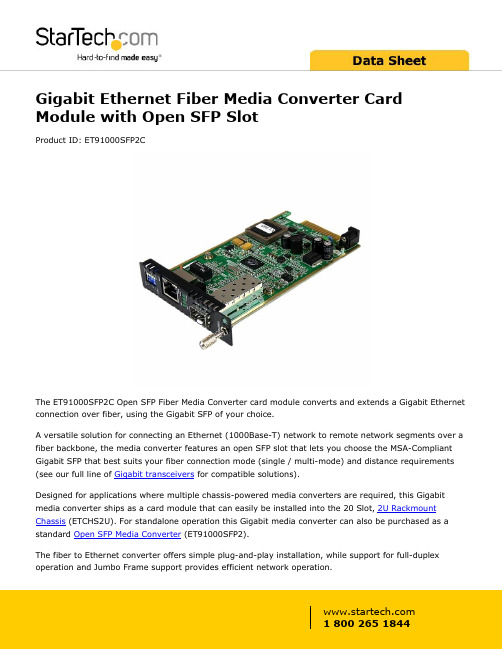
Gigabit Ethernet Fiber Media Converter Card Module with Open SFP SlotProduct ID: ET91000SFP2CThe ET91000SFP2C Open SFP Fiber Media Converter card module converts and extends a Gigabit Ethernet connection over fiber, using the Gigabit SFP of your choice.A versatile solution for connecting an Ethernet (1000Base-T) network to remote network segments over a fiber backbone, the media converter features an open SFP slot that lets you choose the MSA-Compliant Gigabit SFP that best suits your fiber connection mode (single / multi-mode) and distance requirements (see our full line of Gigabit transceivers for compatible solutions).Designed for applications where multiple chassis-powered media converters are required, this Gigabit media converter ships as a card module that can easily be installed into the 20 Slot, 2U Rackmount Chassis (ETCHS2U). For standalone operation this Gigabit media converter can also be purchased as a standard Open SFP Media Converter (ET91000SFP2).The fiber to Ethernet converter offers simple plug-and-play installation, while support for full-duplex operation and Jumbo Frame support provides efficient network operation.Backed by a 2-year warranty and free lifetime technical support.Certifications, Reports and Compatibility Applications•Mount multiple media converter cards into a rack mount chassis•Cost-effective way to extend/bridge networks using fiber cabling •Provides connectivity to a user or network segment that is in an isolated area of a large complex or in another building altogether•Perfect for secure connections required by government agencies where EMI is not acceptable•Connect traffic control/monitoring systems at extreme distances to the main office•Extend network connectivity to remote areas of stadiums,auditoriums or other venuesFeatures•Media Converter card module designed for installation into the ETCHS2U Rackmount Chassis•Open SFP slot supports MSA-Compliant Single / Multi-Mode Gigabit SFPs at varying distances•Advanced features include Link-loss forwarding, remote monitor status, two frame lengths•Supports full or half-duplex operation•Easy to use and install•Jumbo Frame supportWarranty 2 YearsHardware Chipset ID Marvell - 88E1111Industry Standards IEEE 802.3ab 1000BASE-TIEEE 802.3z 1000BASE-LXIEEE 802.3z 1000BASE-SXPoE NoWDM NoPerformance Auto MDIX YesFiber Operating Mode Half/Full-DuplexMaximum Data Transfer Rate 1.25 GbpsMTBF65, 000 HoursConnector(s)Local Unit Connectors 1 - RJ-45 Female1 - SFP Slot FemaleSpecial Notes / Requirements Note Fiber data transfer speeds and distances are dependent onthe SFP used (sold separately)Power Center Tip Polarity PositiveInput Current 1 AInput Voltage12V DCPlug Type MPower Consumption (In Watts)< 8WPower Source Not Included (not required for standard applications) Environmental Humidity10~90% RH (Non-Condensing)Operating Temperature0°C to 60°C (32°F to 140°F)Storage Temperature-10°C to 70°C (14°F to 158°F)PhysicalCharacteristicsProduct Height0.8 in [2.1 cm]Product Length 5.6 in [14.2 cm]Product Width 2.9 in [74 mm]Weight of Product 3.9 oz [110 g]PackagingInformationPackage Height 1.1 in [27 mm]Package Length7.3 in [18.5 cm]Package Width 5.1 in [13 cm]Shipping (Package) Weight 6.5 oz [184 g]What's in the Box Included in Package 1 - Fiber Media Converter1 - Instruction Manual Product appearance and specifications are subject to change without notice.。
MD5G10LP 低功耗微波感应雷达模块 产品说明书

MD5G10LP低功耗微波感应雷达模块产品说明书V1.1成都阶跃时进科技有限公司发布2020-11-05目录1.产品概述 (2)2.技术参数 (2)3.接口尺寸 (3)3.1接口 (4)3.2尺寸 (4)4.产品使用说明 (5)4.1感应时间和距离调节 (5)4.2感光检测 (5)4.3模块上电时序图 (6)5.注意事项 (6)6.声明 (6)7.版权说明 (7)1. 产品概述MD5G10LP模块是一款采用5.8GHz频率的低功耗微波感应雷达模块,整体功耗60uA左右,感应距离0.5m~8m可调,模块尺寸 20mm*20mm;可以满足电池供电等应用场景的超低功耗需求,同时可以克服传统PIR(热释电红外传感器)受温度等环境因素干扰、灵敏度低、需要开孔等问题,是PIR升级换代的首选。
MD5G10LP模块完整集成了5.8GHz微波电路、中频放大电路以及信号处理器,集成度高且生产一致性好,外围搭配小型化平面微带天线,保证模块性能的同时大大减小了整体尺寸。
该模块可用于检测人体存在或移动目标感应的各种场景,包括智能家居、物联网以及智能照明等领域,特别适用于小夜灯、太阳能路灯及无线摄像头等由电池供电的低功耗场景2. 技术参数1.主要参数表2.1 MD5G10LP模块主要技术参数2.探测范围雷达模块的感应灵敏度可通过调节电阻来配置,其极限感应距离为6~8米,实际感应距离可根据需要适当调节。
以下典型场景的雷达探测范围示意图,如果灵敏度设置的更高,探测范围也会相应变大,图中深色区域为高灵敏度区域,该区域内可完全探测到,浅色区域为低灵敏度探测区域,该区域内可基本探测到物体。
图2.1 MD5G10LP 模块探测范围示意图(纵轴为面向雷达)3. 接口尺寸图3.1 MD5G10LP 模块实物图a)背面b)正面3.1 接口MD5G10LP模块预留5个间距2.54mm的排针接口,共有VCC、GND、OUT、P2和P3五个信号,如需调谐距离和延迟时间等参数,可通过P2,P3的悬空或拉低状态配合模块上特定电阻来选择相应档位或者用模块上预留的外置MCU 来改写内部参数。
DELL optiplex-3010用户手册

Dell OptiPlex 3010 小型塔式计算机 用户手册
管制型号: Байду номын сангаас12M 管制类型: D12M001
HP TFT7600机架式一体化键盘显示器用户指南

简介 ........................................................................................................................................................ 5 TFT7600 RKM 的功能 ................................................................................................................................ 5 组件 ........................................................................................................................................................ 6 背面组件.................................................................................................................................................. 7
校园网核心网络设备设备清单
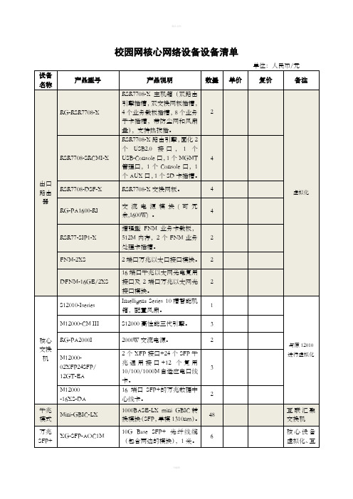
校园网核心网络设备设备清单
注:为保护原有投资,要求原有SAM认证计费系统可用、实现基于用户路由策略的出口联动及核心交换机的虚拟化冗余,此清单要求采用锐捷产品。
校园网运维管理设备清单
注:基于校园网络设备多数为锐捷产品,推荐锐捷RIIL产品。
校园网IP服务管理设备清单
注:推荐阿姆瑞特、锐捷品牌。
业务应急与运维保障系统设备清单
单位:人民币/元
注:业务应急支持6台物理机或12台虚拟机应用系统。
推荐上海数腾产品。
虚拟化云计算服务器设备清单
单位:人民币/元
注:为保障与原云计算虚拟化平台实现统一虚拟化管理,最大程度保障应用系统安全、可靠、稳定运行,此清单要求采用H3C产品。
中心机房迁移等设备清单
注:
1.所需光纤、跳纤均为单模,波长1310nm。
2.光纤切割熔接,涉及到光纤回引,留足冗余保证光纤切
割熔接正常,测试通过可以正常使用。
3.所有服务器、交换机、刀箱服务器搬迁入新中心机房之
前进行一次除尘处理。
总清单。
带IPLINK的MEDIALINK控制器
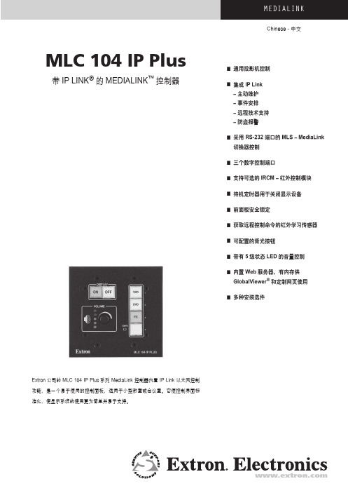
MEDIALINKChinese - 中文MLC 104 IP Plus■ 通用投影机控制带IP LINK®的MEDIALINK™ 控制器■集成 IP Link– 主动维护– 事件安排– 远程技术支持– 防盗报警■ 采用 RS-232 端口的 MLS – MediaLink切换器控制■ 三个数字控制端口■ 支持可选的IRCM – 红外控制模块■ 待机定时器用于关闭显示设备■ 前面板安全锁定■ 获取远程控制命令的红外学习传感器■ 可配置的背光按钮■ 带有5级状态LED的音量控制■ 内置Web 服务器,有内存供GlobalViewer®和定制网页使用■ 多种安装选件Extron公司的 MLC 104 IP Plus系列 MediaLink 控制器内置 IP Link 以太网控制功能,是一个易于使用的控制面板,适用于小型教室或会议室。
它使控制界面标准化,使显示系统的使用更为简单并易于支持。
描述特性 (续)DVD/VCRз ЫExtron MLC 104 IP PlusMediaLinkExtron SI 3CT LPϴExtron MPA 122պTCP/IPExtron MLC 104 IP Plus MediaLink 控制器是一种易于使用的控制面板,适用于小型教室或会议室。
设计用于控制各种小型音视频系统,并具有 Extron 创新的IP Link 以太网控制技术,可以进行远程诊断、设备资产管理和技术支持。
MLC 104 IP Plus 将所有系统的控制界面标准化,简化基于投影机和切换器系统的使用。
界面的标准化也使安装和维护支持变得更加容易。
灵活的MLC 104 IP Plus 起到了一个扩展的远程控制面板的作用。
它不是切换器,而是控制器,它告诉投影机或切换器什么时候在各种输入信号间进行切换。
使用者无需培训或只需简单培训,就可以直接进入多媒体教室或会议室来操作这种音视频系统。
MLC 104 IP Plus 中带有通用投影机控制,利用 Extron 预置的驱动程序,为投影机的电源开关、输入切换和音量调整进行控制。
施耐德_最新上架式工控机产品产品目录
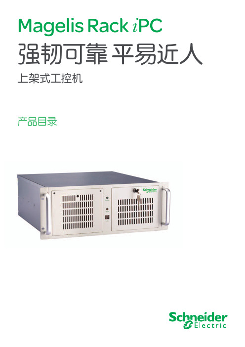
Վೕഗ
ةఄೡ
߾ײၜణ
एԨᆘॲದዃ
Magelis ฉॐ๕߾੦ऐဣଚ༵ࠃଇದዃࠃስǖ b Քጚ႙ǖHMIRHAPP00SLj० ྺSE-RPC-S b કቛ႙ǖHMIRHAPP00HLj० ྺSE-RPC-H
ኄଇۼದᆶǖ b ټᆶڦཱ֫ޫݞዷӱLjܱܔଝ߾ᄽ࣍ৣᆶ߸ࡻڦᆌႠ
6 COM4 连接器端口
6
7 COM2 连接器端口
7
8 并口 ( 打印机口 )
8
9 音频输入、输出接口
10 USB1- USB4 端口
11 VGA 视频接口
3
产品规格
Magelis Rack iPC
0
上架式工控机
产品规格
型号 系统
显示
存储
扩展插槽
网络 I/O 接口
看门狗 定时器 电源 冷却 外部设备 操作系统 尺寸 重量 环境
2
产品布局
Magelis Rack PC
0
上架式工控机
12
11 10 9
5
10
HMIRHAPP00S
12
产品布局
前端
6
1 LED 电源指示灯
2 重启按钮
4 7
3 电源开关
3
4 LED 硬盘指示灯
5 USB5, USB6
6 可读写光驱
7 硬盘 1
8 硬盘 2 ( 扩展版机型 )
9 机箱风扇
10 滤网
温度
湿度 振动 冲击
标准版机型 HMIRHAPP00S
扩展版机型 HMIRHAPP00H
Intel Pentium dual-Core , 2.6G
Intel G41/ICH7R 双通道, DDR3,标配 2G,最大可扩展到 4G
- 1、下载文档前请自行甄别文档内容的完整性,平台不提供额外的编辑、内容补充、找答案等附加服务。
- 2、"仅部分预览"的文档,不可在线预览部分如存在完整性等问题,可反馈申请退款(可完整预览的文档不适用该条件!)。
- 3、如文档侵犯您的权益,请联系客服反馈,我们会尽快为您处理(人工客服工作时间:9:00-18:30)。
计用于控制各种小型音视频系统,采用 Extron 创新的 IP Link 以太网控制技 术进行远程诊断、设备管理和系统支持。MLC 104 IP Plus 提供通用的显示 控制、红外学习功能、3 路数字输入 / 输出,并支持 IRCM — 红外控制模块。 MLC 104 IP Plus 分带标准面板或不带标准面板两种,而标准面板中又分带 一个 AAP 开口或讲台面板两种。
႙ࠓऻ/ܵ३ᇉ
႙ࠓൿೊߔ
႙ࠓശ३ᇉ
Extron
SI 3CT LP ಊၿმใ߁ϴ လശచ
DVD/VCR ቊފ
з࠾Ы
MLC 104 IP Plus 带 IP Link 的 MLC - MediaLink 控制器
专有特性 ● 双单元面板 ● 随附 MR 200 双单元底圈
MediaLink™
垂询电话:400.883.1568 |
接下页 酉 ˝
第六章 MEDIALINK™
6 控 制 器
TCP/IP ་૰
ڟ༄ PC
MLC 104 IP Plus 系列(续)
RS-232 ࠋ ާທཐ႙ࠓ ३ᇉ
DISPLAY OFF
ON
VOLUME
1 VCR
2 DVD
专有特性 ● 8.1 厘米高的薄形面板与讲台或桌面上的紧凑空间完全匹配 ● 使用 Extron UCM RAAP 通用控制器机架安装套件,将其安装在机架内
产品编号
60-8iaLink™
型号
MLC 104 IP Plus L
黑色
MLC 104 IP Plus L
产品编号
60-818-32 60-818-33
产品编号
60-818-00
˝
串行控制端口 波特率及协议 以太网控制端口 以太网数据速率 以太网协议
RS-232 ( 双向 ) 、2.5mm 微型立体声插孔 × 1 ( 前面板 ) 38400 波特,8 位,1 个停止位,无奇偶校验 RJ-45 ×1 10/100 Base-T、全双工 / 半双工通信 ( 自动选择 ) ARP, DHCP, ICMP (ping), TCP/IP, Telnet, HTTP, SMTP
型号
MLC 104 IP Plus
黑色
MLC 104 IP Plus
白色
产品说明
产品编号
60-818-02 60-818-03
MLC 104 IP Plus DV+ 带 IP Link 和集成 DVD 和 VCR 红外控制的 MLC - MediaLink 控制器
专有特性 ● 四单元面板 ● 集成的双功能 DVD 和 VCR 红外控制 ● 附带黑色和白色两种耐冲击性塑料安装面板
[ 仅限 MLC 104 IP Plus] MR 200 — 2 单元底圈(用于 AAP 面板) [ 仅限 MLC 104 IP Pllus AAP] MR 400 — 4 单元底圈(用于 AAP 面板)
MediaLink International Faceplate Labels — MediaLink 国际通用面板标签
3.5mm 3 针螺丝锁定器 × 1 (RS-232( 双向 )、±5 V)
MLC 104 IP Plus 系列附件 EPS 1210 B — AC 适配器将电源从 100-240 VAC(50/60Hz)转换成 12 VDC, 1A
NETXC M-M — 1.8 米网络电缆(带 RJ-45 公 - 公连接器)
Backlit Button Labels — 带背光按钮标签
波特率及协议 (RS-232)
红外控制端口 数字输入 / 输出控制 数字输入 数字输出
115200 〜 300 baud ( 初始值:9600 baud)
红外端口控制 3.5mm 2 针螺丝锁定器 × 1 (TTL 电平 (0 〜 5V) 红外控制 — 直到 1 MHz)
一般规格
12 VDC,1 A 由随机附带适配器 (100VAC - 240VAC,50/60Hz) 供电 100 VAC - 240 VAC (50/60 Hz)
工作温度范围
0°C 〜 50°C ( 无冷凝 )
产品重量 尺寸 ( 不计突出部分 )
约 0.9 kg
面板 MLC 104 IP Plus :宽 117 mm × 高 114 mm × 深 3 mm ( 接线配件标准板 - 2 单元 ) MLC 104 IP Plus AAP:宽 212 mm × 高 114 mm × 深 3 mm (4 单元 ) MLC 104 IP Plus L :宽 165 mm × 高 80 mm × 深 3 mm 设备 所有型号 :宽 89 mm × 高 70 mm × 深 59 mm
第六章 MEDIALINK™
MLC 104 IP Plus 系列
带 IP Link 的 MLC - MediaLink 控制器
MLC 104 IP Plus 系列
MediaLink™
6
简介
控 制 器 主要规格
Extron MLC 104 IP Plus 系列控制器兼具增强的功能和更大的价值。其设
主机端口控制
Extron 基于 Windows® 的全局配置程序 Extron 简单指令集 (SIS™) Microsoft® Internet Explorer, Telnet
30 kHz 〜 62 kHz
从前面板 5.1 cm 〜 30.5 cm
串行端口控制 3.5mm 3 针螺丝锁定器 × 1 (RS-232 ( 双向 )、±5 V)
型号
MLC 104 IP Plus DV+
黑色和白
˝
垂询电话:400.883.1568 |
产品说明
产品编号
60-818-82
接下页 酉
第六章 MEDIALINK™
MLC 104 IP Plus AAP 带 IP Link 和 AAP 开口的 MLC - MediaLink 控制器
专有特性 ● 四单元面板 ● 可容纳多达四个单格 AAP — 结构化安装适配板的开口 ● 随附 MR 400 四单元底圈
MLC 104 IP Plus 系列(续)
型号
MLC 104 IP Plus AAP
黑色
MLC 104 IP Plus AAP
白色
产品说明
MLC 104 IP Plus L 带 IP Link 和讲台面板的 MLC - MediaLink 控制器
3 PC
4
CONFIG MLC 104 IP Plus
Extron
ON LIMITEORFF
STEREO
LEVEL
DMUOANLO
TREBLE BMAINSISPOWERMAPMAPL1IF2IE2R
Extron MPA 122
ີྜੵ܃٦պచ
ၿ S-൮
൮
RGBHV ၿ
Extron MLC 104 IP Plus MediaLink ३ᇉచ
白色
产品说明
MLC 104 IP Plus 带 IP Link、无面板的 MLC - MediaLink 控制器
专有特性 ● 无面板,用于定制安装 ● 与任何 MLM 104 系列安装选件配合使用
型号
MLC 104 IP Plus
只带控制器 — 无面板
产品说明
垂询电话:400.883.1568 |
共同特性 ● 用于通用显示控制的双向 RS-232 端口 ● IP Link 以太网监控 ● 三个数字输入 / 输出端口 ● 支持可选的 IRCM — 红外控制 ● 对外部信号源进行定制控制的模块 ● 用于信号源控制的专用红外端口 ● 用于支持 MLS — MediaLink 切换器的 RS-232 端口 ● 待机定时器用于关闭显示 ● 红外学习功能
数字输入 / 输出控制 端口数字输入 / 输出 × 3、3.5mm 4 针螺丝锁定器 × 1
输入电压范围 :0 〜 12V DC 输入阻抗 :28 kΩ 可编程负载 :2 kΩ 〜 +5 V DC
反向电流 :最大 250 mA(24 VDC)
域值 电源电压
Low 〜 High :DC 2.0 V 以上、High 〜 Low :DC 0.8 V 以内
以太网默认设置
SCP 控制端口 程序控制 红外学习频率 红外学习距离
显示控制 切换器控制 ( 用于 Extron 切换器 )
链路速度和双工电平 ( 自动检测 ) IP 地址 =192.168.254.254、子网掩码 =255.255.0.0 默认网关 =0.0.0.0 DHCP=OFF
3.5mm 5 针螺丝锁定器 × 1
