IMAT
锐速刀(RapidArc)放射治疗系统优势介绍
锐速刀(RapidArc)放射治疗系统优势介绍锐速刀(RapidArc)是瓦里安公司生产的一种采用容积旋转调强治疗技术即VMAT 技术(Volumetric ModulatedArc Therapy,VMAT)的放疗设备, 又可称为旋转调强。
它是在传统调强放疗(IMRT)及图像引导放射治疗(IGRT)基础上,机架360度范围内单弧或者多弧旋转,通过改变机架角度、机架旋转速度、MLC、剂量率、准直器等,优化束流,从而达到满足临床需求的新技术,理论上可实现最优的治疗实施效率和计划质量。
该技术基于IMRT、IGRT,且有更多的可调节参数,因此能够提供适形度更高、剂量分布更为真实准确的治疗计划,减少正常组织的受量,降低放射反应。
BEAM ON时同时调整机架的旋转、MLC的形状及输出剂量率,一般患者的治疗时间能够控制在2分钟以内,患者舒适度更好,由体位变化引起的治疗误差更小。
该设备还在确保达到优化剂量分布的前提下,使机器MU最小,相比传统的IMRT能大幅降低MU,节约了设备,提高了效率,同时由于低MU辐照使诱发肿瘤的可能性降低。
锐速刀的一体化解决方案锐速刀(RapidArc)技术应用于临床和治疗以来,国外许多研究表明计划质量优于三维适形放疗,效果优于传统调强照射。
对于危及器官的保护较好,且因其旋转特性,在射野方向上具有较大的自由度,使得剂量分布趋向更紧密,降低了与靶区相邻危及器官的高剂量受照体积,靶区的适形度更好。
锐速刀(RapidArc)作为一种容积调强放疗,在旋转过程中辐照范围是整体靶区,所以不存在螺旋断层调强放疗射野间剂量衔接的问题,其实施效率也远高于螺旋断层放疗。
由于锐速刀(RapidArc)可以制定并实施非共面IMAT计划,使得其优势更明显。
锐速刀的突出优势锐速刀(RapidArc)系统不仅具有速度快、效果好的特点,打击起肿瘤来具有“稳、准、狠”的特点,还扩大了放射治疗的范围,特别是对以往有肿瘤发生多处转移的患者,采用传统放射治疗效果均不甚理想,而根据临床显示,运用该系统进行治疗将达到良好的效果。
心电监护仪基础知识学习材料图文.
•理邦-智能精准的快速血压技术(iCUFS)血压 算法
(1)灵活的预充气压力设置,方便门诊&急诊等科室点测 需要。 (2)双通道保护以及能量检测技术(专利)最大程度的保证 病人在测量过程中的安全。 (3)袖带识别技术(专利),有效保证了新生儿免受误用 的额外压力伤害。 (4)自适应的放气技术(专利),有效降低测量时间,最 大保证病人舒适性。 (5)智能的脉搏波模板匹配技术,有效识别心律失常、运 动,转运等带来的干扰,提高在心内科,急诊科的测量准 确性。
理邦心电参数优势:
• iSEAP心电算法通过欧洲CSE数据库和美国AHA、MIT数据库 及专家小组的权威测试 。
• iSEAP算法提供更准确的心率、心律失常、ST段监护功能。
• iSEAP算法获得2项专利,能提供更准确的ST分析能力和更强 的抗干扰能力。
• 理邦监护可配12导联心电,具备12导联心电自动分析诊断功 能。
- 麻醉深度(BIS)
心电( ECG )监测
• 心电监测项目:
1 . 心电波形监测 2 . 心率监测 3 . 心律监测(心律失常分析) 4 . ST段分析
•什么是心电图?
在心动周期中,心脏每次 机械收缩之前,必先产生电激 动,电流传布 全身,各处产生 不同的电位。因电流强度与方 向不断变动,身体各电位也不 断变动,心电监测把这种变动 的电位连续描记成的曲线即为 心电图。通过监测心电图,对 于诊治各种疾病有重要的意义 。
• 心电监测项目-心率
➢ 心率(HR):心脏每分钟跳动的次数。 ➢ 脉率(PR):每分钟心脏有效跳动产生动脉搏动
的次数。
➢ HR与PR的关系:正常情况下HR=PR ,在发生某些 心律失常(如房颤)时,心脏的跳动未能引起脉 搏的产生(即无效心跳),此时HR>PR。
美国社区应急预案建设

美国社区应急预案建设是确保社区在面临自然灾害、人为事故等紧急情况时,能够迅速、有序地开展救援和恢复工作的重要措施。
经过多年的发展,美国的社区应急预案建设已形成一套较为完善的体系,以下将从几个方面对美国社区应急预案建设进行阐述。
一、应急管理体系美国社区应急预案建设的基础是建立完善的应急管理体系。
1979年,美国成立了联邦应急事务管理总署(FEMA),负责协调全国防灾、减灾、备灾、救灾和灾后恢复工作。
FEMA下设多个部门,如国家事件管理援助小组(IMAT)、社区应急响应团队(CERT)等,共同构建起多层次、全方位的应急管理体系。
二、社区应急响应团队(CERT)CERT计划是美国社区应急预案建设的重要组成部分。
该计划通过教授基本的灾害应对技能,如急救、灭火、搜索与救援等,增强社区在灾害中自我应对的能力。
CERT成员在灾害发生时,可以迅速组织救援力量,协助专业救援队伍开展救援工作。
目前,全美50个州及许多部落都有CERT计划,已有超过60万人接受了培训。
三、应急演练与培训为了提高社区应对紧急情况的能力,美国社区应急预案建设强调应急演练与培训。
社区定期组织应急演练,检验应急预案的有效性,提高居民应对紧急情况的能力。
同时,通过培训,使社区居民掌握必要的应急技能,提高自救互救能力。
四、应急物资储备与保障美国社区应急预案建设注重应急物资储备与保障。
社区根据实际情况,储备足够的应急物资,如食品、药品、帐篷、应急照明设备等,确保在灾害发生时,能够迅速满足居民的基本生活需求。
五、信息沟通与宣传信息沟通与宣传是美国社区应急预案建设的关键环节。
社区通过多种渠道,如电视、广播、互联网等,向居民发布应急信息,提高居民对紧急情况的认知和应对能力。
同时,社区定期开展应急知识宣传活动,提高居民的自救互救意识。
六、社区参与与合作美国社区应急预案建设强调社区参与与合作。
政府与社区、企业、社会组织等各方共同参与应急管理工作,形成合力。
社区通过成立应急志愿者队伍,充分发挥居民在应急管理工作中的作用。
CAT3516控制面板翻译
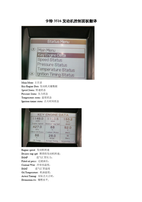
卡特3516发动机控制面板翻译Main Menu 主目录Key Engine Data 发动机关键数据Speed Starus 转速状态Pressure Status 压力状态Temperature status 温度状态Ignition timine status 点火时间状态Engine speed: 发动机转速Desirec eng spd: 期望的发动机转速;IMAP 进气汇管压力;Filtrd oil press: 过滤油压;Coolant Watr: 冷却水温度;IMAT 进气汇管温度Oil Temperature: 机油温度;Actual Timing: 实际点火正时;Detonation lvi: 爆燃水平;Engine speed: 发动机转速;Desired End spd: 期望的发动机转速;Eng High Idie Sp: 发动机高怠速速度;Speed Control: 速度控制电流;Rated Speed: 最高/额定速度;Eng Lo Idle spd: 怠速转速;Throttle Cmd: 风门开度:Filtrd oil press: 过滤后机油压力;Diff oil press: 发动机机油压差;IMAP:汇管空气压力;Coolant Press: 冷却水压力;IMAT: 汇管空气温度;Coolant Water: 冷却水温度;Oil Temperature: 机油温度;Even Bank: 平均温度;Desired Timing: 期望的点为时间;Actual Timing: 实际点火时间;Speed Droop: 速降比Detonation lvi: 爆燃水平;Service Hours: 服务小时;Battery Voltage: 直流电压;Software Part#: 软件代号;Installed ETM inst status;ETM安装状态Engine mode switch: 发动机模式转换开关;Initiate contact status: 启动控制开关;Auxiliary driven equip status: 驱动设备状态;Emergency STOP: 紧急停机;Pre-lube switch :润滑油加热开关Pre-lube relay: 润滑油压力开关Starter motor relay:启动马达开关Fuel control relay: 燃料气控制状态;Crank term spd 300RPM 曲轴转动圈数Crank term relay ENERGIZED; 曲轴位置感应通电Run Relay ENERGIZED 运行Fault relay OFF 故障Cooldown duration 0 min 冷却水降温持续时间Remaining cooldown time 0 sec 最后冷却时间Engine control alarm status off 发动机控制系统的报警状态Battery votage 23.5volts 直流电源电压Exhaust NOx: 排气管中NOx浓度Fuel valve cmd :燃料气阀门的开度;IMAP:进气汇管压力;IMAT:进气汇管温度;Fcf: 燃气修正因数HOME:返回首页PAGE UP: 上翻页Fn:功能键STEP: 步骤ESC ACK: 返回/撤销AUTO MAN: 自动/手动PAGE DOWN: 下翻页SETUP ENTER: 回车/ 确定RESET: 刷新/复位RUN STOP: 起动/停机TEST: 测试(在运行时,运行参数与理论参数的差异)TIMER “0”: 时间测试TIMERS: 时间设置COMP ROD LOAD LBS: 压缩机连杆负载C: 磅T: 华氏温度ST: 运行状态RPM: 转速HRS: 运转时间SUCTION P : 进气压力DISC: 排气压力DISC #2 P: 2#压缩缸排气压力COMP OIL P: 压缩机机油压力COMP OIL T: 压缩机机油温度YL1 DISC T: 1#缸出气口温度……Setup Menu:主目录Login:注册/进入系统Event List:故障列表Process Setpoints:运行参数设置Administrator Menu:管理员菜单Clear Event List:清除故障列表Set Date & Time:设置日期和时间Force Menu:技术/软件菜单FAULT SNAPSHOT: 故障及时记录Time时间Shtdn:停机Engine Over speed:发动机超速SPEED CONTROL PID: 速度控制CTRL ON:Suction 进气阀门:开MODE: Manual:模式:手动TGT RPM OUT: 瞬时转速MAN RAP SP: 手动输入转速。
迟子峰-河北医科大学第四医院科研处
科学技术进步奖公示内容一、项目名称:精准放疗物理学多中心联合系统研究二、提名单位:河北省卫生和计划生育委员会三、项目简介:近年来,放射治疗技术、剂量验证设备及质量控制(QC)和质量保证(QA)手段快速发展,但新技术对治疗链中涉及的QC 和QA以及剂量验证设备等一系列相关问题提出了更高要求。
由于单一放疗中心,放疗技术、验证设备及人力、财力资源相对有限,因而其研究成果相对单一缺乏应用广泛性。
本研究旨在通过多中心联合研究,在保证放疗设备、放疗计划、计划验证和验证设备整体质控精度的基础上结合大宗病例数据,完整和系统的研究分析了放疗新技术包括Tomotherapy、VMAT、IMAT、IMRT、CyberKnife等在治疗各部位肿瘤间的优缺点及临床应用情况,通过评估和总结,为临床治疗采用合理新型技术提供依据和指导,为精准治疗指导下的个体化治疗提供临床数据,在精确放放射治疗基础上进一步提高肿瘤的局部控制率。
研究内容主要包括放疗设备的测量验收及整体质控、多种放疗技术在治疗全身不同部位肿瘤时的优缺点分析、通过多种质控技术方法验证各治疗技术投照实施时的精度、各种剂量验证技术在质量控制方面的特性对比分析、以及自适应放疗共五大部分研究,实际达到的性能指标如下:首次全面总结了放疗设备QA临床使用规范,为同行提供放疗设备质控建议。
首次在国内外通过多中心联合,结合大宗病例数据,完整和系统的研究分析了新技术在治疗不同部位肿瘤间的优缺点及临床应用情况,进行了评估和总结,为临床治疗采用合理新型技术实施精准放疗提供依据和指导。
首次在国内外对电离室点剂量验证,胶片EDR2、矩阵Matrixx、矩阵MapCheck二维剂量验证和Delta4、Arccheck三维剂量验证等主流剂量验证技术在质量控制方面的特性进行了相互对比分析,针对放射治疗新技术进行全方位的质量验证与实时质控研究,确定了各新型技术在实施临床患者治疗时的可靠性和治疗精度。
放疗常用英文词汇
放疗常用英文词汇缩略语中英文对照3D- CRT 3dimensional comformal radiation therapy 三维适形放射治疗ABC active breath control 主动呼吸控制技术ABMT autologous bone marrow transplantation 自体骨髓移植AF accelerated fractionation 加速分割AHF accelerated hyperfractionation 加速超分割ART adaptive radiotherapy 适应性照射AT Ataxia Talangiectasia 毛细血管扩性共济失调BD basal dose 基准剂量BED biologically effective dose 生物等效剂量BEV beam eye view 射束方向视图BMI body mass index 身体质量指数BOLD blood-oxygen-level-dependent 血氧水平依赖法BRMs biological response modifiers 生物反响调节剂BTV biological target volume 生物靶区CBHART concomitant boost hyperfractionated accelerated radiation therapy 同时小野加量加速超分割放疗CCG Children’s Cancer Group 儿童癌症研究组织CDK cyclin-dependent kinase 细胞周期依赖性蛋白激酶CF conventional fractionation 常规分割CHART continuous hyperfractionated accelerated radiation therapy 连续加速超分割放疗CI coverage index 靶区覆盖指数CIN cerbical intraepithelial neoplasia 宫颈上皮瘤变CLDR continuous low dose rate radiotherapy 抵剂量率持续照射CML cutaneous malignant lymphoma 皮肤恶性淋巴瘤CPV coach’s preview 床角预览视图CT computed tomography 计算机体层显影CTV clinical target volume 临床靶区CUP carcinoma of unknown primary 原发灶不明的转移癌DDCs dermal dendritic cells 真皮树突状细胞DFS disease free survival 无瘤生存DMF dose modifying factor 剂量修饰因子DPC DNA protein cross-linking DNA-蛋白质交联DRF dose reduction factor 剂量减少系数DRR digitally reconstructed radiography 数字重建图像DSA digital subtractive angiography 数字减影血管造影DSB double strand break 双链断裂DVH dose volume histograms 剂量-体积直方图EBF electron backscatter factor 电子反向散射因子ECM extracellular matrix 细胞外基质EGFR epithelial growth factor receptor 表皮生长因子受体EHART escalating hyperfractionated accelerated radiation gherapy 逐步递量加速超分割放疗EI external volume index 靶外体积指数EPID electronic portal imaging device 电子射野影像系统EUD dffective uniform dose 等效均一剂量18F-FDG 18F-fluorodeoxyglucose 氟代脱氧葡萄糖FCCL follicular center cell lymphoma 滤泡中心性淋巴瘤FDF fractionation-dosage factor 分次剂量因子FHDR fractionated high dose rate brachytherapy 高剂量率分次近距离治疗FL-HCC fibrolamellar hepatocellular carcinoma 纤维板层样肝细胞肝癌FNH focal nodular hyperplasia 局灶性结节增生FSRT fractionated stereotactic radiotherapy 分次立体定向放射治疗FSU functional subunits 功能亚单元GCT germ cell tumor生殖细胞瘤GTV gross tumor volume 肿瘤靶区或肉眼靶区HA hepatocellular adenoma 肝细胞腺瘤HC hyperthermia and chemotherapy 热疗加化疗HCC hepatocellular carcinoma肝细胞肝癌HD hyperdose sleeve超剂量区HF hyperfractionation超分割HI relative dose homogeneity index靶区剂量均匀性指数HR hyperthermia and radiation 热疗加放疗HRC hyperthermia and radiochemotherapy 热疗加放化疗HVL half value layer 半价层IC immunocytoma 免疫细胞瘤ICR interval cytoreductive or intervening cytoreduction 间隔细胞减灭术ICRU International Commission on Radiation units and Measurements 国际辐射单位与测量委员会IGART image guided adaptive radiotherapy 影像学引导的适应性照射IGRT image guided radiotherapy影像学引导的放射治疗IM internal margin 边界IMAT intensity modulated arc therapy 弧形调强技术IMRT intensity modulated radiation therapy 调强放射治疗IM-WPRT intensity-modulated whole pelvic radiotherapy 全盆调强放射治疗IPSID immunoproliferative small intestinal disease 免疫增值性小肠病ISO international Organization for Standardization 国际标准化组织ITV internal target volume 靶区IV irradiation volume 照射靶区KCs keratinocytes表皮胶原细胞LCHART late-course hyperfractionated accelerated radiation therapy 后程加速超分割放疗LCs Langerhans cells 朗罕氏细胞LD lethal damage 致死损伤LENT late effective normal tissues正常晚反响组织LET linear energy transfer 线性能量传递LH local hyperthermia 局部加温LI labeling index 标记指数LLS linear least squares线性最小二乘法LQ linear quadratic model LQ 模型或线性二次模型MCD mean central dose 平均中心剂量MIMiC multivaane intensity modulation compensator多叶调强补偿器MLC multileaf collimator 多叶准直器MRI magnetic resonance imaging磁共振成像MTD minimum target dose 最小靶剂量MTH mild temperature hyperthermia 温和加温MU monitor unit 机器跳数NCCN National Comprehensive Cancer Network美国综合癌症工作者NED no evidence of disease无疾病证据NF neurofibromatosis神经纤维瘤病NHL non-Hodgkin Lymphoma 非霍奇金淋巴瘤NSCLC non-small cell lung cancer非小细胞肺癌NSD nominal standard dose名义标准剂量NSGCT nonseminomatous germ cell tumor非精原细胞性生殖细胞瘤NTCP normal tissue complication probability正常组织并发症概率OAR off axial ratio离轴比OAR organ at risk敏感器官OER oxygen enhancement ratio氧增强比OI overdose volume index超剂量体积指数OPM ocult primary malignancy隐匿原发灶OUF output factor射野输出因子PCI propylactic cranial irradiation预防性全脑照射PCML primary cutaneous malignant lymphoma 原发性皮肤恶性淋巴瘤PDD percentage depth dose百分深度剂量PDRR pulsed dose rate brachytherapy 脉冲剂量率近距离治疗PET positron emission tomography 正电子发射断层扫描PF protection factor 防护系数PLD potential lethal damage 潜在致死损伤PNAd peripheral node addressin 外周淋巴结地址素PNETs primitive neuroectodermal tumor 原始神经外胚层肿瘤POA pancreatic oncofetal antigen 胰腺癌胚抗原PSA prostate specific antigen 前列腺特异抗原PT precision radiotherapy 准确放疗PTCA percutaneous transluminal coronary angioplasty经皮腔冠状动脉成型术PTV planning target volume 计划靶区PUC probability of uncomplicated control 无并发症控制概率PUFA polyunsaturated fatty acid 多不饱和脂肪酸QA/QC quality assurance/quality control 质量保证/质量控制QOL quality of life 生活质量QP quadratic programming二次规划法RBE relative biological effectiveness相对生物效应RD reference dose参考剂量REV room's eye view 治疗室视图RH regional hyperthermia区域加温SAD source axis distance源轴距SALT skin associated lymphoid tissue皮肤相关淋巴样组织SAR scatter air ratio散射空气比SCHART split-course hyperfractionated accelerated radiation therapy分段加速超分割放疗SCLC small cell lung cancer 小细胞肺癌SER sensitization enhancement ratio增敏比SI sum index加权综合指数SIB simultaneously integrated boosting大野照射与小野追加剂量照射SIOP International Society for Paediatric Oncology国际儿童肿瘤研究组织SIS skin immune system皮肤免疫系统SLD sublethal damage亚致死损伤SLN sentinel lymph node哨位淋巴结SLNB sentinel lymph node biopsy哨位淋巴结活检技术SM set-up margin摆位边界SMR scatter maximum ratio散射最大剂量比SOBP spread out Bragg peak扩展布拉格峰SPECT single photo emmision computerized tomography单光子发射型计算机扫描SPR scatter phantom ratio散射体模比SRS stereotactic radiosurgery立体定向放射外科SRT stereotactic radiation therapy立体定向放射治疗SSB single strand break单链断裂SSD source skin distance源皮距STD source tumor distance源瘤距SVCS superior vena cave syndrome上腔静脉综合征SVD singular value decomposition奇异值分解法TAA tumor associated antigen肿瘤相关抗原TAE transcatheter arterial embolization经导管动脉栓塞术TAR tissue air ratio组织空气比TCD tumor control dose肿瘤控制剂量TCP tumor control probability肿瘤控制概率TER thermal enhancement ratio热增强比TGF therapeutic gain factor治疗增益系数〔因子〕TLD thermoluminescence dosimeters热释光剂量计TMR tissue maximum ratio组织最大剂量比Tpot potertial doubling time潜在倍增时间TPR tissue phantom ratio组织体模比TPS treatment planning system 治疗计划系统TR therapeutic ratio治疗比TSEI total skin electron irradiation电子线全身照射TV treatment volume治疗靶区TVR treatment volume ratio治疗体积比UDS unscheduled DNA synthesis程序外DNA合成UICC International Union Against Cancer国际抗癌联盟VEGF vascular endothelial growth factor血管皮生长因子WBH whole body huperthermia全身加温5 放射肿瘤学〔放射治疗学〕5.1 放射肿瘤学radiation oncology原先称放射治疗学,专门研究肿瘤放射治疗的分支学科。
调强放疗

什么是调强放疗?调强放疗(intensity modulated radiation therapy,IMRT)即调强适形放射治疗是三维适形放疗的一种,要求辐射野内剂量强度按一定要求进行调节,简称调强放疗。
它是在各处辐射野与靶区外形一致的条件下,针对靶区三维形状和要害器官与靶区的具体解剖关系对束强度进行调节,单个辐射野内剂量分布是不均匀的但是整个靶区体积内剂量分布比三维适形治疗更均匀。
严格地说,使用楔形板和常规的表面弯曲补偿器也是调强。
但这里我们所说的调强放射治疗是指一种形式的三维适形放射治疗,它使用计算机辅助优化程序不获取单个放射野内非均匀的强度分布以达到某种确定的临床目的。
下面要讲的就是这个意义上的调强放射治疗。
编辑本段调强分布的设计1、正向计划设计调强放疗在CT影像上勾画好解剖轮廓后,三维适形放射治疗是由计划者根据靶区部位和大小在计划系统上安排照射野的入射方向、大小、形数目并对各个辐射野分配权重然后由计算机系统进行剂量计算,算完后显示射野分布,计划者依据靶区及正常组织所受剂量来评估计划的好坏。
如果剂量分布不符合治疗要求,再由计划者改变射野的入射方向和权重,重新计算,如此反复进行,直至满意为止。
这种制定计划的方式叫做正向计划设计。
2、调强放疗多采用逆向计划设计方案调强概念是受了CT成像的逆原理启发:当CT的X射线管发出强度均匀的X射线穿过人体后,其强度分布与组织厚度和组织密度的乘积成反比;那么我们不是可以先确定射线照到靶区及正常组织上产生的剂量分布,然后再由此推算出各个射野应该贡献的束流强度吗?根据调强的概念,首先要依据病变(靶区)与周围重要器官和正常组织的三维解剖特点,以及期望的靶区剂量分布和危及器官(OAR)的剂量耐受极限,由计划者输入优化参数,通过计划系统计算出各个射野方向上需要的强度分布。
即在完成勾画轮廓和确定辐射野数目及入射方向后,先确定对CT影像中各个兴趣区的剂量要求。
由计划者以数学形式输入这些临床参数(即目标函数),如对靶区剂量范围的要求,对相关危及器官剂量的限制等,然后由计算机通过数学的方法(如迭代法、模拟[font color=#000000]退火[/font]法、蒙特卡洛法等)自动进行优化,在经过几百乃至上千次计算与比较后得出最接近目标函数并能够实现的计划方案。
旋转调强治疗技术(imat)名词解释
旋转调强治疗技术(imat)名词解释
旋转调强治疗技术(IMAT)是一种用于放射治疗的先进技术。
IMAT结合了旋转射束放射治疗和调强技术,可以在一个旋转
周期内根据患者的病灶位置和形状调整射束强度和方向。
IMAT的关键是使用多叶片旋转式调强装置(MLC)和线性加速器。
MLC由许多可以独立运动的铅叶片组成,可以根据需
要移动以阻挡和形成合适的射束形状。
线性加速器则提供高能量的X射线。
在IMAT治疗中,患者通过立体定位系统定位,然后在一个
旋转周期内,线性加速器和MLC同时旋转,释放高能量X射
线来治疗病灶。
通过精细调整MLC的位置,可实现针对性的
病灶治疗,减少对周围健康组织的伤害。
IMAT具有高度的精确性和适应性,能够根据患者的病情和治
疗需要,提供个体化的治疗计划。
与传统放射治疗相比,
IMAT可以更好地控制治疗区域的剂量分布,提高治疗效果,
同时减少副作用和对健康组织的伤害。
迈达斯建模的几个问题

有关模型建立的基本问题1、关于MIDAS截面面输入的讨论问:请问fem2000兄,为什么只有变截面能导入已定义的PSC截面,必须先定义PSC截面,而其他变截面为什么不能导入(除PSC之外),且手工输入葙梁截面数据似乎太慢了,请问有还有没有其他便捷的输入截面方法,最主要的是解决葙梁截面输入,如桥博的节线输入,坐标输入,我觉得MIDAS的输入法应该不会比其他软件差的(单位新买的正版的MI DAS,小弟在初步学习之中)答:(1)以在EXCEL里面编辑好,在拷贝到截面表格里面哦(2)在添加截面时候,有个导入功能,可以导入原先做过截面数据!如以前有相同或类似的就方便了许多。
不妨试下。
(3)可以充分利用midas的截面特性计算器以及mct文件编辑器,截面的cad图你该有吧?将cad图存成dxf文件,导入截面特性计算器,不过要注意图形文件不能有面域,只能是线,因为他可以进行批量计算,所以你只要将所有截面放到一张图里,然后进行计算,最后导出mct文件,假若说是变截面,可以用mct的命令流将你得到的mct文件进行编辑,然后就可以导入变截面了。
(4)mct命令窗口中对各项mct命令都有提示,只要点插入命令你就能得到那个命令的命令流格式,如果对各项所代表的意义不明白可以参考在线帮助,相对来说,要比ansy s的命令流好学多了,毕竟他有中文帮助。
你从spc导出来的mct文件里面给出的是section里的value格式,你可以参照value 跟tapered之间的差别,将你得到的value 截面1,2拷贝到tapered形式里作为i,j截面,以此类推,然后修改其中的部分不同内容,就会得到了你想要的。
在编辑的时候推荐你用ultraedit编辑器,主要的方便之处是它可以进行行快和列快的转换,至于说怎么能提高编辑的效率,可以慢慢摸索,只要熟练了,看起来麻烦的事也会变得非常简单。
(5)MIDAS变截面输入可以采用变截面组的方式!一个变截面的梁,可以定义变截面组,变截面组里面包括你所需要的变截面单元,此时把变截面组的所有单元设成一种变截面类型,变截面组的i端就是变截面的i端,j端就是变截面的j端!在变截面组里面i端到j端的截面特性是均匀变化的,可以定义成按线形或者多项式变化!变截面组可以再转换成变截面,此时,每个变截面组里的单元都会赋予不同的截面类型,同时,变截面组也会被删除!注意:在截面对话框的“数值表单”中定义的变截面不能使用该功能。
医学物理-肿瘤放射治疗

在线校准—超声引导摆位系统 (BAT)
自适应放疗
自适应放 疗是根据 治疗过程 中的反馈 信息,对 治疗方案 作相应调 整的治疗 技术或模 式。
治疗中的呼吸运动管理—ABC
Active Breathing Coordinator (ABC) 患者主动参与 并进行深吸深呼- 再次深 吸- 屏气这一 过程的呼吸训 练,在屏气时 靶区暂时停止 运动,给予放
治疗前 治疗后
放疗技术—镭
镭管、镭针、镭模等,用于治疗皮肤癌和比 较表浅的恶性肿瘤。
放疗技术—X线治疗机
20世纪30、40年代:KV级X线治疗机的出现成 就了外照射技术(远距离治疗)的发展。
放疗技术—钴治疗机
。 20世纪50年代,钴-60远距离治疗机的出现标志着兆伏级放疗时代的开始
放疗技术—加速器
PPRRIIMMUUSS oorr PPRRIIMMAARRTT
ZZXXTT TTaabbllee
Gantry Moves During Slice Acquisition
Stationary Carbon Fiber Tabletop Rails
SSOOMMAATTOOMM CCTT SSlliiddiinngg GGaannttrryy
实时跟踪技术
• 实时跟踪技术(Real-time Tumor Tracking) 随着成像技术,多叶光栅以及机械控制技术的 发展,实时跟踪肿瘤运动使射线束实时跟随目 标肿瘤,成为肿瘤运动补偿问题的发展方向。
• 最常用的直接跟踪方法是通过X 射线透视成像 对运动肿瘤实时成像。通常为了增加肿瘤与周 围软组织的图像对比度, 常在患者体内植入 金属标记物。
医学物理
——肿瘤放射治疗
医学物理简介
肿瘤放射治疗常用英文缩写

1.RTRadiotherapy,Radiation Therapy放疗,放射治疗放射治疗是利用放射线治疗肿瘤的一种方法,是当今治疗肿瘤的三大手段之一。
据统计,大约有60~70%恶性肿瘤患者需要接受放射治疗。
有些恶性肿瘤通过放疗可以得到根治,并可能获得同类同期肿瘤的手术治疗的疗效,且可保存所在的器官及其功能。
2.IMRTIntensity Modulated Radiation Therapy调强放射治疗调强放射治疗与以往放射治疗技术不同,它通过调节各个方向照射野的野内射线的强度产生非均匀照射野,达到肿瘤的高剂量三维适形分布和危及器官的低剂量分布,从而提高肿瘤的照射剂量,尽可能地减少危及器官和正常组织的受量,最终提高肿瘤局部的控制率,改善肿瘤患者的生存质量。
3.MLCMultiLeaf Collimator多叶准直器,多叶光栅MLC最初设计主要是用于替代射野挡铅,后来发展成了IMRT的基础,控制叶片运动可实现静态MLC和动态MLC调强。
4.QA & QCQuality Assurance & Quality Control质量保证和质量控制放射治疗的QA是指经过周密计划而采取的一系列必要的措施,保证放射治疗的整个服务过程中的各个环节按国际标准准确安全的执行。
这个简单的定义意味着质量保证有两个重要内容:质量评定,即按一定标准度量和评价整个治疗过程中的服务质量和治疗效果;质量控制,即采取必要的措施保证QA的执行,并不断修改服务过程中的某些环节,达到新的QA级水平。
5.AAPMAmerican Association of Physicists in Medicine美国医学物理学家协会6.SADSource to Axis Distance源轴距放射源到机架旋转或机器等中心的距离。
SSDSource to Surface Distance源皮距放射源到模体表面照射野中心的距离。
3DCRT、X刀、IMRT等技术都采用SAD技术,国内常规放疗正在普及SAD等中心照射技术,希望大家能尽早放弃SSD技术,只在某些特定情况下采用SSD技术。
卷烟零售客户诚信互助小组工作亮点

卷烟零售客户诚信互助小组工作亮点英文回答:Highlight of the Integrity and Mutual Assistance Team (IMAT) for Tobacco Retail.IMAT's Mission: To promote a culture of integrity and collaboration within the tobacco retail industry, the Integrity and Mutual Assistance Team (IMAT) works to prevent and detect illicit tobacco sales, protect youth, and ensure compliance with tobacco laws and regulations.Key Highlights:Enhanced Collaboration: IMAT fosters partnerships between tobacco retailers, law enforcement, and industry stakeholders to combat illicit trade and underage sales.Training and Education: IMAT provides comprehensive training programs for retailers on tobacco laws, youthaccess prevention, and responsible sales practices.Compliance Checks: IMAT conducts compliance checks to verify compliance with tobacco laws and regulations. Non-compliant retailers face appropriate consequences.Intelligence Sharing: IMAT facilitates the exchange of information and intelligence among stakeholders to identify and address emerging trends in illicit tobacco activity.Community Engagement: IMAT works with community organizations and youth advocacy groups to promote awareness about the harms of underage tobacco use.Consumer Reporting: IMAT provides a confidential mechanism for consumers to report suspected illicit tobacco sales or underage purchases.Industry Support: IMAT receives support from leading tobacco manufacturers and distributors who are committed to combating illicit trade and protecting youth.Impact and Accomplishments:Reduced illicit tobacco sales by 25% in targeted areas.Trained over 10,000 tobacco retailers on responsible sales practices.Conducted thousands of compliance checks, resulting in significant enforcement actions.Established a network of community partners dedicatedto preventing youth tobacco use.Enhanced the industry's reputation as a responsible player in reducing tobacco-related harms.中文回答:卷烟零售客户诚信互助小组工作亮点。
老年肌脂肪变性的研究进展
国际老年医学杂志 2023年5月 第44卷第3期 IntJGeriatr,May2023,Vol.44No.32023国际老年医学杂志编辑部 2023bytheEditorialOfficeofInternationalJournalofGeriatrics新疆维吾尔自治区自然科学基金项目(2022D01C635) 通讯作者:程新春,电子邮箱2272871234@qq com老年肌脂肪变性的研究进展李 蕊1 李 淼1 程新春21新疆医科大学研究生院,乌鲁木齐 830001;2新疆维吾尔自治区人民医院老年医学中心,乌鲁木齐 830001 [摘 要] 肌脂肪变性是指肌肉中病理性脂肪浸润,随着年龄的增长而增加,与肌肉质量、力量和流动性呈负相关,是一种不同于肌少症和少肌性肥胖的疾病。
肌脂肪变性与许多衰老相关的不良结局有关,如活动能力障碍、代谢障碍和死亡率增加。
胰岛素抵抗、线粒体氧化磷酸化受损、肌肉中脂质氧化减少以及年龄相关的肌肉干细胞向脂肪细胞的分化都被认为是导致肌脂肪变性的潜在机制。
本文就肌脂肪变性的诊断与评估、与老年相关疾病的关系、预防及治疗的最新进展进行综述。
[关键词] 肌脂肪变性;脂肪浸润;疾病 doi:10 3969/j issn 1674-7593 2023 03 024ResearchProgressofMyosteatosisintheElderlyLiRui1,LiMiao1,ChengXinchun21GraduateSchoolofXinjiangMedicalUniversity,Urumqi 830001;2GeriatricsCenter,ThePeople’sHospitalofXinjiangUighurAutonomousRegion,Urumqi 830001Correspondingauthor:ChengXinchun,email:2272871234@qq com [Abstract] Myosteatosisisthepathologicallipidaccumulationinmuscle.Themorbidityincreaseswithagingandisnega tivelycorrelatewithmusclemass,strengthandmobility.Itisnotthesamediseaseassarcopeniaandsarcopenicobesity.Itisassoci atedwithmanyage-relatednegativeconsequences,suchasobstaclestomobility,metabolicdisorderandincreasingmortality.Insu linresistance,impairedmitochondrialoxidativephosphorylation,diminishedlipidoxidationinmuscleandage-relateddifferentiationofmusclestemcellsintoadipocyteshavebeensuggestedaspotentialmechanismscontributingtomyosteatosis.Thispaperreviewstheresearchprogressofmyosteatosisdiagnosisandevaluation,therelationshipwithelderlydiseases,anditspreventionandtherapy. [Keywords] Myosteatosis;Lipidaccumulation;Disease 肌脂肪变性是指肌肉中病理性脂肪浸润,脂肪累积在肌肉间和肌肉内脂肪组织,或者以脂滴形式累积于肌细胞内,在CT图像上显示为低肌肉放射密度[1-2]。
IMRT的基本概念和临床应用

MIMiC
MIMiC – Mini-multileaf collimator – Multileaf intensity-modulating collimator – Multivane intensity-modulating collimator
计划分为1cm和2cm两种
Beamlet“开关”问题 – 气动
安装在加速器上用于临床
IMRT计划的分类
正向设计 – 多为静态野
逆向设计 – 静态野 – 动态野 – 旋转野
IMRT实现的方式(一)
二维物理补偿器 – 二维滤过板、补偿膜、移动条
多叶准直器(MLC) – 静态(SMLC)- 剂量率稳定,将广泛应用
Subfield MLC、Segments MLC step and shoot、stop and shoot
MIMiC的优缺点
优点 – 旋转照射,剂量分布好 – 尤其1CM计划对复发NPC有优势 – 摆位精度高(1%毫米)
缺点 – Gap and overlap – 照射体积大 – 照射时间长 – 床的移动需人工操作
剂量率调节示意图
IMRT的物理学问题
靶区的勾画 – 肿瘤体积的准确
颈淋巴预防区域
Boost的可行性
– 无融合计算软件
原发鼻咽癌
约120例 局控率好、失败为远处转移 残留病例的处理 重要器官的保护
复发鼻咽癌
约120例 CR60%以上 颅底骨质破坏者效果差
– 本身是否是复发 – 易坏死 海绵窦复发、桥脑小脑角复发 二程放疗并发症:坏死、出血、头痛
பைடு நூலகம்瘤
脑膜瘤:消退方式 星形细胞瘤、胶质细胞瘤:局控好 室管膜瘤:CR 垂体瘤:CR,消退方式 松果体瘤:CR 转移癌:有效,无优势,与全身状况有关
MCT命令_02_MCT

MCT命令_02_MCTMCT 命令简要说明l 功能MCT 命令的功能、使用方法的简要说明。
Unit SystemEnd DataProject Information单位系; FORCE, LENGTHFORCE : MCT File 建立时所使用的荷载单位 {tonf} LENGTH : MCT File 建立时所使用的长度单位{m} Data 的输入完了项目的基本情况PROJECT, REVISION, USER, EMAIL, ADDRESS, TEL, FAX, CLIENT, TITLE, ENGINEER, EDATE, CHECK1, CDATE1, CHECK2, CDATE2, CHECK3, CDATE3, APPROVE, ADATE, COMMENT PROJECT : 项目名称REVISION : 最终修改日期USER : 用户EMAIL : E-MAIL 地址ADDRESS : 地址TEL : 电话号码FAX : 传真号码CLIENT : 客户TITLE : 项目的小标题ENGINEER : 操作人EDATE : 操作日期CHECK1 : 第一次核对人CDATE1 : 第一次核对日期T UNIT T ENDDATAT PROJINFOStructure TypeDefine Line GridCHECK3 : 第三次核对人CDATE3 : 第三次核对日期APPROVE : 最终负责人ADATE : 最终确认日期COMMENT : 注释结构分析所需的基本数据; iSTYP, iSMAS, GRAV, TEMPER, bALIGNBEAM, bALIGNSLABiSTYP : 结构形式 {0}= 0 : 3维分析= 1 : 2维分析 (X-Z 平面)= 2 : 2维分析 (Y-Z 平面)= 3 : 2维分析 (X-Y 平面)= 4 : 3维分析 (约束Z 方向旋转自由度)iSMAS : 指定是否将模型的自重换算成质量 {0}= 0 : 不换算成质量= 1 : 换算成质量并考虑为全局坐标系的X 、Y 、Z 方向= 2 : 换算成质量并考虑为全局坐标系的X 、Y 方向= 3 : 换算成质量并考虑为全局坐标系的Z 方向GRAV : 重力加速度值 {9.806 m/sec 2}TEMPER : 热应力分析时所需的初始温度bALIGNBEAM : 将主梁上部排放在Floor Level (YES/NO) {NO}bALIGNSLAB : 将楼板上部排放在Floor Level (YES/NO) {NO}T STRUCTYPET GRIDLINENodesElements节点数据; iNO, X, Y, ZiNO : 节点编号X : 全局坐标系X 方向坐标Y : 全局坐标系Y 方向坐标Z : 全局坐标系Z 方向坐标单元数据; iEL, TYPE, iMAT, iPRO, iN1, iN2, ANGLE, iSUB, EXVAL ; Frame Element; iEL, TYPE, iMAT, iPRO, iN1, iN2, iN3, iN4, iSUB, iWID ; Planar Element; iEL, TYPE, iMAT, iPRO, iN1, iN2, iN3, iN4, iN5, iN6, iN7, iN8 ; Solid Element1. Frame ElementiEL : 单元编号TYPE : 单元种类= TRUSS : 桁架单元= BEAM : 梁单元= TENSTR : 只受拉单元= COMPTR : 只受压单元iMAT : 材料编号iPRO : 截面编号iN1 : 第一个节点编号iN2 : 第二个节点编号ANGLE : Beta AngleiSUB : Sub Type对于TRUSS : 无关对于BEAM : 无关对于TENSTR {1}= 1 : Truss= 2 : Hook= 3 : Cable对于COMPTR {1}= 1 : TrussT NODE T ELEMENTEXVAL : 对单元需另行输入的数据对于TRUSS : 无关对于BEAM : 无关对于TENSTR= Truss : 无= Hook : 输入Hook的距离 = Cable : 输入Pretension 对于COMPTR= Truss : 无= Gap : 输入Gap的距离2. Planar ElementiEL : 单元编号TYPE : 单元种类= PLATE : 面单元= PLSTRS : 平面应力单元= PLSTRN : 平面变形单元= AXISYM : 轴对称单元iMAT : 材料编号iPRO : 截面编号iN1 : 第一个节点编号iN2 : 第二个节点编号iN3 : 第三个节点编号iN4 : 第四个节点编号iSUB : Sub Type对于PLATE {1}= 1 : Thick= 2 : Thin对于PLSTRS : 无关对于PLSTRN : 无关对于AXISYM : 无关3. Solid ElementiEL : 单元编号TYPE : 单元种类= SOLID : 实体单元iMAT : 材料编号iPRO : 截面编号iN1 : 第一个节点编号iN3 : 第三个节点编号iN4 : 第四个节点编号iN5 : 第五个节点编号iN6 : 第六个节点编号iN7 : 第七个节点编号iN8 : 第八个节点编号T MATERIALMaterial等方性材料的材料特性; iMAT, TYPE, MNAME, [DATA]; STEEL, CONC, USER; iMAT, TYPE, MNAME, [DATA], [DATA] ; SRC; [DATA] : 1, DB, NAMEor 2, ELAST, POISN, THERMAL, DEN iMAT : 材料编号TYPE : 材料种类= STEEL : 钢材= CONC : 混凝土= SRC= USER DEFINEMNAME : 材料名称[DATA] 1DB : 各国家标准截面的DB= KS(S) : Korean Industrial Standards(45种钢材的数据库)= KS-CIVIL(S) : 27种钢材的数据库= ASTM(S) : American Society for Testing Materials (40种钢材的数据库)= JIS(S) : Japanese Industrial Standards(23种钢材的数据库)= DIN(S) : Deutsches Institut fur Normung(11种钢材的数据库)= BS(S) : British Standard(23种钢材的数据库)Time Dependent Material Function= KS(RC) : 19种混凝土材料的数据库= KS-CIVIL(RC) : 19种混凝土材料的数据库= ASTM(RC) : 7种混凝土材料的数据库= JIS(RC) : 16种混凝土材料的数据库NAME : DB 的名称[DATA] 2ELAST : 弹性系数POISN : 泊桑比THERMAL : 线热膨胀系数DEN : 单位体积的重量材料的颜色数据; iMAT, W_R, W_G, W_B, HF_R, HF_G, HF_B, HE_R, HE_G, HE_B, bBLEND, FACTiMAT : 材料编号W_R : 以Wire Frame 显示时Red 的颜色编号W_G : 以Wire Frame 显示时Green 的颜色编号W_B : 以Wire Frame 显示时Blue 的颜色编号HF_R : Hidden 处理面的Red 颜色编号HF_G : Hidden 处理面的Green 颜色编号HF_B : Hidden 处理面的Blue 颜色编号HE_R : Hidden 处理面边线的Red 颜色编号HE_G : Hidden 处理面边线的Green 颜色编号HE_B : Hidden 处理面边线的Blue 颜色编号bBLEND : 是否指定颜色的透明度(YES/NO) {NO}FACT : 颜色透明度指定系数 {0.5}混凝土的徐变/干缩函数; FUNC=NAME, FTYPE, SCALE, CTYPE,ELAST, DESC ; line 1; DAY1, VALUE1, DAY2, VALUE2 ; from line 2 T MATL-COLORT TDM-FUNCTime Dependent Material= CREEP : 徐变= SHRINK : 干缩SCALE : 增减系数CTYPE : Creep Function Data Type= SC : Specific Creep= CF : Creep Compliance= CC : Creep CoefficientELAST : 混凝土的弹性系数DESC : 简单的说明DAY1: 时间VALUE1 : 徐变(干缩)数据值时间依存材料数据(徐变、干缩); NAME=NAME, CODE, STR, HU, CURE, VOL, SLUMP, FAP, AIR, AGE, CC, IMCP ; CODE=ACI; NAME=NAME, CODE, STR, HU, MSIZE, CTYPE, AGE ; CODE=CEB, KS; NAME=NAME, CODE, N1, PHI1, N2, PHI2; CODE=MEM; NAME=NAME, CODE, bSSF, SSFNAME; CODE=USER(line1); CREEPFUNC1, AGE1, CREEPFUNC2, AGE2, ...; USER(from line 2)1. 共同事项NAME : 时间依存材料名CODE : 时间依存材料的DB= ACI : American Concrete Institute= CEB : CEB-FIP= KS : Korean Industrial Standards= MEM : Modify Elasticity Modulus, 通过修改弹性系数来考虑徐变= USER : 用户直接输入材料数据2. ACISTR : 28天压缩强度HU : 外界湿度T TDM-TYPESLUMP : 混凝土塌落度FAP : 细骨材比AIR : 含气量AGE : 浇筑后开始干缩的时间CC : 水泥量IMCP : 初期湿润养护时间3. CEBMSIZE : 建筑物的几何模型指数CTYPE : 水泥种类= RS : Rapid hardening high strength cement= NR : Normal or rapid hardening cement= SL : Slowly hardening cement4. MEMN1 : 从0(day)到N1(day)的天数PHI1 : 弹性系数的折减系数5. USERbSSF : 是否采用Shrinkage Strain FunctionSSFNAME : 所要采用的干缩函数CREEPFUNC1 : 所要采用的徐变函数AGE1 : 开始加荷时的材龄T TDM-ELASTTime Dependent Material(Comp. Strength)随时间而变化的混凝土弹性系数(压缩强度); NAME=NAME, TYPE, CODE, STRENGTH, A, B ; TYPE=CODE(Korean Standard, ACI); NAME=NAME, TYPE, CODE, STRENGTH, iCTYPE ; TYPE=CODE(CEB-FIP, Ohzagi); NAME=NAME, TYPE, SCALE; TYPE=USER(line 1); DAY1, VALUE1, DAY2, VALUE2, ...; USER(from line 2)1. 共同事项Time Dependent Material Link的函数名TYPE : 弹性系数(压缩强度)变化的输入方法= CODE : 选择规范定义的混凝土特性= USER : 用户直接输入弹性系数变化CODE : 选择的规范名= Korean Standard= ACI= CEB-FIP= Ohzagi2. KS 、ACISTRENGTH : 在各材龄混凝土的压缩强度= KS : 材龄91天混凝土的压缩强度= ACI : 材龄28天混凝土的压缩强度A, B : 混凝土的压缩强度系数3. CEB-FIP 、OhzagiiCTYPE : 水泥种类系数= 1 : Rapid hardening high strength cement = 2 : Normal or rapid hardening cement= 3 : Slowly hardening cement= 4 : 使用Fly ash 时4. USERSCALE : Scale Factor(增减系数)DAY1 : 时间VALUE1 : 弹性系数值将材料的时间依存特性赋予已输入的材料数据; iMAT, TDM-TYPE1(CREEP/SHRINKAGE), TDM-TYPE2(ELASTICITY)iMAT : 被赋予时间依存特性的材料编号TDM-TYPE1(CREEP/SHRINKAGE) :在Time Dependent Material (Creep/Shrinkage)选择所定义的T TDM-LINKChange Element Dependent Material Property Section在Time Dependent Material (Elasticity)选择所定义的材料变更自动计算时间依存特性时所采用的几何模型指数(h); ELEM_LIST, HELEM_LIST : 所要变更的单元编号H : 几何模型指数(h, Notational Size of Member)桁架单元或梁单元的截面数据; iSEC, TYPE, SNAME, OFFSET, SHAPE, [DATA]; DB/USER; iSEC, TYPE, SNAME, OFFSET, SHAPE, BLT, D1, D2, D3,D4, D5, D6 ; 1st line – VALUE; AREA, ASy, ASz, Ixx, Iyy, Izz; 2nd line; CyP, CyM, CzP, CzM, QyB, QzB, PERI_OUT,PERI_IN ; 3rd line; iSEC, TYPE, SNAME, OFFSET,SHAPE, iREPLACE, ELAST, DEN, POIS, POIC ; 1st line - SRC; D1, D2, [DATA] ; 2nd line; iSEC, TYPE, SNAME, OFFSET, SHAPE, 1, DB, NAME1, NAME2, D1, D2 ; COMBINED; iSEC, TYPE, SNAME, OFFSET, SHAPE, 2, D11, D12,D13, D14, D15, D21, D22, D23, D24; iSEC, TYPE, SNAME, OFFSET, SHAPE, iyVAR, izVAR, STYPE ; 1st line - TAPERED; DB, NAME1, NAME2 ; 2nd line(STYPE=DB); [DIM1], [DIM2] ; 2nd line(STYPE=USER); D11, D12, D13, D14, D15, D16; 2nd line(STYPE=VALUE); AREA1, ASy1, ASz1, Ixx1, Iyy1, Izz1; 3rd line(STYPE=VALUE)T ELEM-DEPMATLT SECTION; D21, D22, D23, D24, D25, D26; 5th line(STYPE=VALUE); AREA2, ASy2, ASz2, Ixx2, Iyy2, Izz2; 6th line(STYPE=VALUE); CyP2, CyM2, CzP2, CzM2, QyB2, QzB2, PERI_OUT2, PERI_IN2 ; 7th line(STYPE=VALUE); [JOINT]-i ; 2nd line(STYPE=PSC); [OUTER-H]-i ; 3rd line(STYPE=PSC); [OUTER-B]-i ; 4th line(STYPE=PSC); [INNER-H]-i ; 5th line(STYPE=PSC); [INNER-B]-i ; 6th line(STYPE=PSC); [JOINT]-j ; 7th line(STYPE=PSC); [OUTER-H]-j ; 8th line(STYPE=PSC); [OUTER-B]-j ; 9th line(STYPE=PSC); [INNER-H]-j ; 10th line(STYPE=PSC); [INNER-B]-j ; 11th line(STYPE=PSC); iSEC, TYPE, SNAME, OEESET, STYPE1, STYPE2; 1st line - CONSTRUCT; SHAPE, ...(same with other type data from shape) ; Before (STYPE1); SHAPE, ...(same with other type data from shape) ; After (STYPE2); iSEC, TYPE, SNAME, OFFSET, SHAPE; 1st line - COMPOSITE-B ; Hw, tw, B, Bf1, tf1, B2, Bf2, tf2 ; 2nd line; N1, N2, Hr, Hr2, tr1, tr2 ; 3rd line; SW, GN, CTC, Bc, Tc, Hh, EsEc, DsDc; 4th line; iSEC, TYPE, SNAME, OFFSET, SHAPE; 1st line -COMPOSITE-T; Hw, tw, B, tf1, B2, tf2; 2nd line; SW, GN, CTC, Bc, Tc, Hh, EsEc, DsDc; 3rd line; iSEC, TYPE, SNAME, OFFSET, SHAPE; 1st line - PSC; JO1, JO2, JO3, JI1, JI2, JI3, JI4, JI5; 2nd line; 3rd line; BO1, BO1-1, BO1-2, BO2, BO2-1, BO3; 4th line; HI1, HI2, HI2-1, HI2-2, HI3, HI3-1, HI4, HI4-1,HI4-2, HI5 ; 5th line; BI1, BI1-1, BI1-2, BI2-1, BI3, BI3-1, BI3-2, BI4; 6th line; [DATA] : 1, DB, NAME or 2, D1, D2, D3, D4, D5, D6; [DIM1], [DIM2] : D1, D2, D3, D4, D5, D6; [JOINT] : JO1, JO2, JO3, JI1, JI2, JI3, JI4, JI5; [OUTER-H] : HO1, HO2, HO2-1, HO2-2, HO3, HO3-1; [OUTER-B] : BO1, BO1-1, BO1-2, BO2, BO2-1, BO3; [INNER-H] : HI1, HI2, HI2-1, HI2-2, HI3, HI3-1, HI4, HI4-1, HI4-2, HI5; [INNER-B] : BI1, BI1-1, BI1-2, BI2-1, BI3, BI3-1, BI3-2, BI41. 共同事项iSEC : 截面编号TYPE : 截面特性种类= DBUSER : 在DB输入的、或者其它定型的截面= VALUE : 直接输入截面特性数据= SRC : SRC构件的截面特性= COMBINED : 组合截面的截面特性= TAPERED : 非单一截面的截面特性= CONSTRUCT : 组合前后的截面特性= COMPOSITE-B= COMPOSITE-T= PSC :SNAME : 截面名称OFFSET : 指定截面中心的位置= LT : Left-Top= CT : Center-Top= RT : Right-T op= LC : Left-Center= CC : Center-Center= RC : Right-Center= LB : Left-Bottom= CB : Center-Bottom= RB : Right-BottomSHAPE : 截面的形状符号(参考表1)1st LineBLT : 区分构件的制作方法{Built}= Built : 焊接型钢(Built-Up Section)= Roll : 轧制型钢(Rolled Section)D1 : 截面的第一尺寸D2 : 截面的第二尺寸D3 : 截面的第三尺寸D4 : 截面的第四尺寸D5 : 截面的第五尺寸D6 : 截面的第六尺寸2nd LineAREA : 截面面积ASy : 单元坐标系y轴方向的有效剪截面面积ASz : 单元坐标系z轴方向有效剪截面面积Ixx : 单元坐标系x轴方向的扭转刚度Iyy : 单元坐标系y轴方向的截面弯矩Izz : 单元坐标系z轴方向的截面弯矩3rd LineCyP : 自中和轴到单元坐标系(+)y方向最外端的距离CyM : 自中和轴到单元坐标系(-)y方向最外端的距离CzP : 自中和轴到单元坐标系(+)z方向最外端的距离CzM : 自中和轴到单元坐标系(-)z方向最外端的距离QyB : 作用于单元坐标系y轴方向的剪切系数QzB : 作用于单元坐标系z轴方向的剪切系数PERI_OUT : 截面外轮廓周长PERI_IN : 截面内轮廓周长3. SRC1st LineiREPLACE : 计算组合截面刚度的材料1=Steel {1}ELAST : 型钢和混凝土的弹性系数比DEN : 型钢和混凝土的比重比POIS : 型钢的泊桑比POIC : 混凝土的泊桑比2nd LineD1 : 混凝土截面的第一尺寸D2 : 混凝土截面的第二尺寸DB : 各国家标准截面的DBNAME1, NAME2 : 构成组合截面的两种单位截面的名称D1 : 截面的第一尺寸D2 : 截面的第二尺寸2 : 输入定型截面的主要尺寸时(USER)D11 : 截面的第一尺寸D12 : 截面的第二尺寸D13 : 截面的第三尺寸D14 : 截面的第四尺寸D15 : 截面的第五尺寸D21 : 截面的第六尺寸D22 : 截面的第七尺寸D23 : 截面的第八尺寸D24 : 截面的第九尺寸5. TAPEREDiyVAR : 考虑单元坐标系y轴截面弯距的方法{1} = 1 : 直线形(Linear)= 2 : 抛物线形(Parabolic)= 3 : 三次曲线形(Cubic)izVAR : 考虑单元坐标系z轴截面弯矩的方法{1}= 1 : 直线形(Linear)= 2 : 抛物线形(Parabolic)= 3 : 三次曲线形(Cubic)STYPE : 指定变截面构件的截面形状= DB= USER= VALUE= PSCDB : 各国家标准截面的DBNAME1, NAME2 : 变截面的开始点i端和结束点j端的截面名称2 : 输入定型截面的主要尺寸时(USER)[DIM1], [DIM2]3 : 使用VALUE输入截面时D11 : i端的第一尺寸D13 : i端的第三尺寸D14 : i端的第四尺寸D15 : i端的第五尺寸D16 : i端的第六尺寸AREA1 : i端的截面面积Asy1 : i端单元坐标系y轴方向有效剪截面面积Asz1 : i端单元坐标系z轴方向有效剪截面面积Ixx1 : i端单元坐标系x轴方向扭转刚度Iyy1 : i端单元坐标系y轴方向的截面弯距 Izz1 : i端单元坐标系z轴方向的截面弯距CyP1 : 自i端中和轴到单元坐标系(+)y方向最外端的距离CyM1 : 自i端中和轴到单元坐标系(-)y方向最外端的距离CzP1 : 自i端中和轴到单元坐标系(+)z方向最外端的距离iCzM1: 自i端中和轴到单元坐标系(-)z方向最外端的距离QyB1 : 作用于i端单元坐标系y轴方向的剪切系数QzB1 : 作用于i端单元坐标系z轴方向的剪切系数PERI_OUT1 : i端截面外轮廓周长PERI_IN1 : i端截面内轮廓周长※对j端也以同样的方法输入数据4 : 输入PSC截面时[JOINT]-i (YES/NO)[OUTER-H]-i[OUTER-B]-i[INNER-H]-i[INNER-B]-i[JOINT]-j[OUTER-H]-j[OUTER-B]-j[INNER-H]-j[INNER-B]-j6. CONSTRUCTIONSTYPE1 : 指定组合前截面的截面特性输入形式= DBUSER= VALUE= COMBINED= TAPERED= CONSTRUCTSTYPE2 : 指定组合后截面的截面特性输入形式; 1st line - CONSTRUCTSHAPE : 指定STYPE1、STYPE2的截面形状(表示SHAPE的各参数与各TYPE截面输入形态相同) ※ 2nd line~7th line的内容与各Type的内容相同7. COMPOSITE-B1st lineSHAPE : 指定截面特性的输入方法= B : Box Girder= I : I型Girder= USER : 使用已指定的截面特性2nd lineHw : 除去钢材flange厚度的web的高tw : Web的厚度B : 上部flange的宽Bf1 : Box型构件从web中心到上部flange端部的距离tf1 : 上部flange的厚度B2 : 下部flange的宽Bf2 : Box型构件从web中心到下部flange端部的距离tf2 : 下部flange的厚度3rd lineN1 : 上部flange stiffness的个数N2 : 下部flange stiffness的个数Hr : 上部flange stiffness的宽Hr2 : 下部flange stiffness的宽tr1 : 上部flange stiffness的厚度tr2 : 下部flange stiffness的厚度4th lineSW : 楼板的总宽GN : 所有楼板中钢材的数CTC : 主梁与主梁间的距离Bc : 各钢材有效楼板的宽度Tc : 楼板的厚度Hh : 从钢材的上端到楼板下端的高度EsEc : 钢材和混凝土的弹性系数比8. COMPOSITE-T※参考COMPOSITE-B9. PSCSHAPE : 指定截面内的孔道数= 1CEL : 1个孔道= 2CEL : 2个孔道JO1, JO2, JO3, … : Joint on/off (YES/NO)HO1, HO2, HO2-1,…: 输入外截面的尺寸BO1, BO1-1, BO1-2, …HI1, HI2, HI2-1, … : 输入内截面的尺寸BI1, BI1-1, BI1-2, …[DATA] 1= DB : 各国家标准截面的DB= NAME : DB的截面名称[DATA] 2= D1, D2, D3, D4, D5, D6[DIM1], [DIM2] : D1, D2, D3, D4, D5, D6[JOINT] : JO1, JO2, JO3, JI1, JI2, JI3, JI4, JI5[OUTER-H] : HO1, HO2, HO2-1, HO2-2, HO3, HO3-1 [OUTER-B] : BO1, BO1-1, BO1-2, BO2, BO2-1, BO3 [INNER-H] : HI1, HI2, HI2-1, HI2-2, HI3, HI3-1, HI4, HI4-1, HI4-2, HI5[INNER-B] : BI1, BI1-1, BI1-2, BI2-1, BI3, BI3-1, BI3-2, BI4 L Angle C Channel H H-Section T T-Section B Box P Pipe 2LDouble Angle 2C Double Channel SBSolid RectangleSR Solid Round CCCold Formed ChannelURIB U-Rib OCT OctagonSCOTSolid Octagon TRK TrackSTRK Solid Octago HTRHalf Track1CEL PCS-1CELL表1. 输入截面的形状符号(SNAME)Section Stiffness Scale Factor 2CEL PCS-2CELL截面的颜色数据; iSEC, W_R, W_G, W_B, HF_R, HF_G, HF_B, HE_R, HE_G, HE_B, bBLEND, FACTiSEC : 截面编号W_R : 以Wire Frame 显示时Red 的颜色编号W_G : 以Wire Frame 显示时Green 的颜色编号W_B : 以Wire Frame 显示时Blue 的颜色编号HF_R : Hidden 处理面的Red 颜色编号HF_G : Hidden 处理面的Green 颜色编号HF_B : Hidden 处理面的Blue 颜色编号HE_R : Hidden 处理面边线的Red 颜色编号HE_G : Hidden 处理面边线的Green 颜色编号HE_B : Hidden 处理面边线的Blue 颜色编号bBLEND : 是否指定颜色的透明度(YES/NO) {NO}FACT : 颜色透明度指定系数 {0.5}对线单元的截面特性使用增减系数; iSEC, AREA_SF, ASY_SF, ASZ_SF, IXX_SF, IYY_SF,IZZ_SFiSEC : 选择相应截面AREA_SF : 对于截面面积的增减系数ASY_SF : 对于单元坐标系y 轴方向承受剪力的有效截面面积的增减系数ASZ_SF : 对于单元坐标系z 轴方向承受剪力的有效截面面积的增减系数IXX_SF : 对于单元坐标系x 轴方向的扭转刚度的增减系数IYY_SF : 对于单元坐标系y 轴方向的截面弯距的增减系数IZZ_SF : 对于单元坐标系z 轴方向的截面弯距的增减系数T SECT-COLORT SECT-SCALETapered Section GroupThickness变截面(Tapered Section)构件的群化; NAME, ELEM_LIST, ZVAR, ZEXP, ZFROM, ZDIST, YVAR, YEXP, YFROM, YDISTNAME : 变截面群的名称ELEM_LIST : 从属于变截面群的单元的编号ZVAR : 定义单元坐标系z 轴方向截面形状的变化= Linear : 线性变化= Quadratic : 按2次曲线变化ZEXP : 指定截面形状变化函数的次数(1~2)ZFROM : 定义对称面所需的基准点ZDIST : 从基准点到对称面的单元坐标系x 轴方向的距离YVAR : 定义单元坐标系的y 轴方向截面形状的变化平面单元的厚度数据; iTHK, TYPE, bSAME, THIK-IN, THIK-OUT; TYPE=VALUE; iTHK, TYPE, SUBTYPE, RPOS, WEIGHT; TYPE=STIFFENED, SUBTYPE=VALUE; SHAPE, THIK-IN, THIK-OUT, HU, HL; for yz section; SHAPE, THIK-IN, THIK-OUT, HU, HL; for xz section; iTHK, TYPE, SUBTYPE, RPOS, PLATETHIK; TYPE=STIFFENED, SUBTYPE=USER; bRIB {, SHAPE, DIST, SIZE1, SIZE2, ..., SIZE6}; for yz section; bRIB {, SHAPE, DIST, SIZE2, SIZE2, ..., SIZE6}; for xz section; iTHK, TYPE, SUBTYPE, RPOS, PLATETHIK, DBNAME ; TYPE=STIFFENED, SUBTYPE=DB; bRIB {, SHAPE, DIST, SNAME}; for yz section; bRIB {, SHAPE, DIST, SNAME}; for xz section1. 共同事项T THICKNESS。
放射治疗的方法和种类

等中心定角(SAD)照射 and 旋转(ROT)照射:无论机器转角的
准确性以及病人体位的误差,都能保证射野中心穿过肿瘤或 靶区中心。升床必须准确。
由于模拟定位机的普遍采用,多数钻-60机和医用加速器都 是等中心旋转型,加之SAD和ROT技术给摆位带来的方便和 准确,SAD技术应用越来越多,SSD技术只是对姑息和非标 称源皮距离照射时才会使用。
②等中心定角(SAD)照射
等中心定角(SAD)照射:将机架旋转中心轴置于肿瘤 或靶区中心T上。 特点:只要旋转中心在肿瘤或靶区中心T上,机架转角 的准确性以及病人体位的误差,都能保证射野中心轴通过 肿瘤或靶区中心。
摆位要点:保证升床准确。其升床的具体数字可由模拟 定位机定位确定。(图b) 等中心照射摆位程序:………
O
设定C点为肿瘤的中心点
体外照射常用的技术有三种
• 固定源皮距(SSD)照射技术、 • 等中心定角(SAD)照射技术、 • 旋转(ROT)照射技术。
①固定源皮距(SSD)照射
◎固定源皮距(SSD)照射:即放射源到皮肤的距离固定。 ◎特点:在固定源皮距下,不论机头在何种位置,机架的旋 转中心点都在皮肤上(A点),而肿瘤或靶区中心T放在放射 源S和皮肤入射点A两点连线的延长线上。 ◎摆位要点:机架转角and病人的体位要准确,否则肿瘤中 心T会逃出射野中心甚至射野之外。(图a) 固定源皮距垂直照射摆位程序:………
• 该方法所用核素是开放性的。 应用过程中应注意防护。 • 举例:131I治疗甲状腺癌; 32P治疗癌性胸水、腹水、心包积液; 135钐治形技术由日本学者Takahashi
在1959年提出。 IMRT技术作为 一种新型放疗技术,临床应用时
间较短,只是在近几年才得到迅
- 1、下载文档前请自行甄别文档内容的完整性,平台不提供额外的编辑、内容补充、找答案等附加服务。
- 2、"仅部分预览"的文档,不可在线预览部分如存在完整性等问题,可反馈申请退款(可完整预览的文档不适用该条件!)。
- 3、如文档侵犯您的权益,请联系客服反馈,我们会尽快为您处理(人工客服工作时间:9:00-18:30)。
Home Search Collections Journals About Contact us My IOPscienceIntensity-modulated arc therapy: principles, technologies and clinical implementationThis article has been downloaded from IOPscience. Please scroll down to see the full text article.2011 Phys. Med. Biol. 56 R31(/0031-9155/56/5/R01)View the table of contents for this issue, or go to the journal homepage for moreDownload details:IP Address: 61.173.130.108The article was downloaded on 27/12/2011 at 15:05Please note that terms and conditions apply.IOP P UBLISHING P HYSICS IN M EDICINE AND B IOLOGY Phys.Med.Biol.56(2011)R31–R54doi:10.1088/0031-9155/56/5/R01TOPICAL REVIEWIntensity-modulated arc therapy:principles, technologies and clinical implementationCedric X Yu and Grace TangUniversity of Maryland School of Medicine,Baltimore,MD,USAReceived20September2009,infinal form22December2010Published4February2011Online at /PMB/56/R31AbstractIntensity-modulated arc therapy(IMAT)was proposed by Yu(1995Phys.Med.Biol.401435–49)as an alternative to tomotherapy.Over more thana decade,much progress has been made.The advantages and limitationsof the IMAT technique have also been better understood.In recent years,single-arc forms of IMAT have emerged and become commercially adopted.The leading example is the volumetric-modulated arc therapy(VMAT),asingle-arc form of IMAT that delivers apertures of varying weights with asingle-arc rotation that uses dose-rate variation of the treatment machine.Withcommercial implementation of VMAT,wide clinical adoption has quickly takenroot.However,there remains a lack of general understanding for the planningof such arc treatments,as well as what delivery limitations and compromisesare mercial promotion and competition add further confusion forthe end users.It is therefore necessary to provide a summary of this technologyand some guidelines on its clinical implementation.The purpose of this reviewis to provide a summary of the works from the radiotherapy community that ledto wide clinical adoption,and point out the issues that still remain,providingsome perspective on its further developments.Because there has been vastexperience in IMRT using multiple intensity-modulatedfields,comparisonsbetween IMAT and IMRT are also made in the review within the areas ofplanning,delivery and quality assurance.1.Historical review1.1.Early development that led to IMATAlthough arc therapy can be traced back to the dawn of the20th century(Johns et al1953), arcs involving dynamicfield shaping using a multileaf collimator werefirst described by Takahashi(1965).He described a method of rotational therapy,which we now refer to as conformal arc therapy,where the beam aperture shaped by a multiple leaf collimator(MLC) 0031-9155/11/050031+24$33.00©2011Institute of Physics and Engineering in Medicine Printed in the UK R31dynamically varies to match the beam’s-eye-view(BEV)of the target.In1982,Brahme et al (1982)solved an integral equation for a hypothetical target wrapped around a critical structure to be treated with arc therapy.They demonstrated that in order to deliver a uniform dose to the target while sparing the critical structure,the beam intensities have to be modulated.In 1983,Chin et al proposed and demonstrated that with computer optimization and the freedom afforded by computer-controlled gantry rotation,collimator motion and dose-rate variation,a highly conformal dose distribution can be achieved(Chin et al1983).These initial developments on arc therapy were accompanied and followed by the development and wide adoption of three-dimensional conformal radiation therapy(3DCRT) in the1980s(Perez et al1995).The need for more convenientfield shaping brought MLC to radiotherapy practice.Brahme et al(1988)published a paper showing that if the intensities of radiation can be modulated across a radiationfield,the increased freedom would afford a greater ability to shape the volume of high doses,to better conform to the target than 3DCRT.The motorizedfield shaping capabilities of MLC were quickly explored to modulate the intensities within a radiationfield.Intensity-modulated radiation therapy(IMRT)aims to deliver a highly conformal dose to a tumor,while sparing the surrounding normal tissues and sensitive structures.Convery and Rosenbloom(1992)derived a mathematical formula for realizing intensity modulation with the dynamic movement of a collimator.During1994–95,more works were published to demonstrate the feasibility of using MLC for intensity modulation in either the dynamic mode or static mode(Bortfeld et al1994a,1994b,Yu and Wong1994,Spirou and Chui1994,Stein et al1994,Yu et al1995a).The amount of work on this emerging technology quickly mushroomed,and clinical implementations of the IMRT technique immediately followed(Ling et al1996,Burman et al1997,Chui et al2001).Mackie et al(1993)proposed another form of IMRT using rotational fan beams,called tomotherapy.At the same time,commercial development of tomotherapy was also rendered by NOMOS Corporation(Carol et al1993,Carol1995a,1995b).Intensity modulation was achieved with a binary collimator,which opens and closes under computer control.As the fan beam continuously rotates around the patient,the exposure time of a small width of the fan beam,or a beamlet,can be adjusted with the opening and closing of the binary collimator,allowing the radiation to be delivered to the tumor through the most preferable directions and locations of the patient.The initial commercial system by NOMOS Corporation added the binary collimator onto a linear accelerator and delivered radiation treatments one slice at a time with the slice thickness equal to the width of two beamlets.The treatment table had to be precisely indexed from one slice to the next.Helical tomotherapy was then developed by Tomotherapy,Inc.as a dedicated rotational IMRT system with a slip-ring rotating gantry achieving more efficient delivery by continuous gantry rotation and treatment couch translation.The dosimetric advantages of rotational treatments are illustrated by Shepard et al(1999), which summarizes results from an optimization series performed for a C-shaped target with a sensitive structure in the concavity of the C.For these simulations,all planning parameters, such as percent dose constraints,were held constant except for the number of beam angles. The results are summarized in table1.It was shown that each increase in the number of beam angles led to a more homogeneous dose in the tumor and a lower dose to the sensitive structure.Significant dosimetric improvements continued well beyond the number of beam angles typically used forfixed-field IMRT.It is also noteworthy that the total integral dose is nearly independent of the number of beam angles.Intensity-modulated arc therapy(IMAT)was introduced by Yu(1995b).Like tomotherapy,IMAT delivers photon radiation treatment in an arc manner.Instead of using rotating fan beams as in tomotherapy,IMAT uses rotational cone beams of varying shapes andTable1.Impact of a number of beam angles on plan quality.Reproduced from Shepard et al(1999).No of Obj.funct.Std.dev.in Mean dose Total integralangles value target dose d95to RAR dose30.6650.1240.7470.4882732.550.3180.0900.8140.2152563.370.2420.0640.8670.2062596.890.2220.0640.8550.1922598.3110.2020.0580.8790.1862570.2150.1870.0530.9080.1802542.9210.1760.0490.9120.1712545.1330.1510.0380.9330.1552543.5varying dose weightings to achieve intensity modulation.Starting from the same tomotherapy plan,which approximates the full arc with evenly spacedfixedfields,the strategy was to convert the intensity patterns into multiple segments and deliver with overlapping arcs.Based on the fact that numerous segment configurations can yield the same intensity pattern,it is possible tofind a segment configuration at each beam angle such that segments at successive angles are connected geometrically.The stacks of overlapping beam apertures can then be delivered with multiple overlapping arcs.Through the initial proof-of-principle study,it was shown that IMAT could be a valid alternative to tomotherapy in terms of treatment delivery.However,unlike tomotherapy, IMAT must account for restrictions on MLC movement as the gantry moves from one beam angle to the next.Because deliverability must take priority,an optimalfield shape may have to be altered in order to produce smooth delivery.As a result,plan quality would be adversely affected for some cases.This restriction does not apply to tomotherapy due to the use of a binary MLC.Therefore,tomotherapy should theoretically have the best plan quality(Bortfeld and Webb2009).As compared with tomotherapy,IMAT also has some advantages:(1)IMAT does not need to move the patient during treatment and avoids abutment issues as seen with serial tomotherapy;(2)IMAT retains the ability of using non-coplanar beams and arcs,which has great value for brain and head/neck tumors;(3)IMAT uses a conventional linac,thus complex rotational IMRT treatments and simple palliative treatments can be delivered with the same treatment unit.1.2.Continued efforts in planning and clinical implementationIn spite of the demonstrated advantages,there were limited research activities on IMAT between1995and2006.The potential reasons may lie in the lack of an efficient planning method for IMAT and the lack of commercial interest.This section summarizes the major efforts in the planning and clinical implementation of IMAT during this relatively dormant period.In2000,a phase I clinical trial of IMAT using forward planning was conducted at the University of Maryland(Yu et al2002),to test the safety and feasibility of changing thefield shape during gantry rotation.Fifty patients with cancers of various sites were treated using IMAT.Due to the lack of an IMAT inverse planning system,forward planning was used to determine the arc range and aperture shapes.Arcs were approximated as multiple shaped fields spaced every5◦to10◦around the patient.Multiple coplanar or non-coplanar arcswere allowed.At each beam angle,irregularfield shapes were defined based on the BEV of the planning target volume and normal critical structures.Typically,at a given angle,one field shape conformed to the BEV of the target and additionalfield shapes were set to shield individual critical structures that overlapped the target in the BEV.Because beam rotation and irradiation are concurrent,the delivery is very efficient.A typical treatment with three tofive arcs takes less than10min from start tofinish,which is comparable to conventional techniques. As is the case with most forward planning techniques,these approaches rely heavily on the experience of the planner and could result in sub-optimal plans as well as prolonged planning times.Nonetheless,standard solutions can be developed for less challenging treatment sites, such as the prostate(Ma et al2001).IMAT could also be used to treat a target wrapped around a critical structure,as demonstrated by Cotrutz et al(2000).Another clinical study was conducted at Ghent University Hospital.The aperture shapes werefirst determined based on the BEV of the target and critical structures,similar to the approach adopted by University of Maryland.However,the anatomy-based apertures were further refined by allowing the leaves to move slightly using a greedy search optimization scheme(DeGersem2004).Treatment planning studies were published for rectal cancer and whole abdominopelvic radiation therapy(Duthoy et al2003,2004).Wong et al(2002)formulated the forward planning into a practical approach which they termed simplified IMAT(SIMAT).SIMAT starts by creating multiple arcs based on the BEV of the anatomy,with each arc serving a distinct planning goal such as covering the whole target or protecting one critical structure.The weightings of the arcs were subsequently optimized, assuming a constant dose rate delivery.The SIMAT strategy was applied to various sites including prostate and high-risk endometrial cancer(Bauman et al2004,Wong et al2005).Although these early works kept the rotational IMRT alive,they suffered from the lack of efficient inverse treatment planning methods.On the other hand,most of these early developments on IMAT were rendered with equally spaced beams under the technical limitation that the machine could not vary the dose rate dynamically during gantry rotation.Under the assumption that the machine dose rate has to be constant during arc rotation,Yu et al(2006) proposed a hybrid of IMRT and IMAT to increase delivery effiing an angular cost function to define the angular weights,an arc delivered with a constant dose rate can be supplemented withfixed intensity-modulatedfields at a few most important angles.1.3.Work leading to the commercialization of single-arc IMATIn proposing IMAT as an alternative to tomotherapy,Yu(1995b)predicted that with the increase in the number of gantry angles,the number of intensity levels at each gantry angle can be reduced without degrading plan quality.It was argued that the plan quality is a function of the total number of strata,defined as the product of the number of beam angles and the number of intensity levels.In other words,it is the total number of aperture shape variations that determine the plan quality.Assuming this is true,a single arc with a sufficient number of aperture shape variations would be able to create optimal treatment plans.Many subsequent works have attempted to use a single arc for IMAT.As illustrated by Jiang et al(2005),a single arc with36beam aperture variations under a constant dose rate cannot realize the optimal plan quality.To reach the desired plan quality,one must either increase the number offield segments or apertures,or allow the dose rate to vary during gantry rotation,or both.MacKenzie and Robinson(2002)proposed a technique whereby24equally spaced beam orientations are optimized for sliding window IMRT and arc delivery is performed by allowing the gantry of the linear accelerator to rotate to static gantry orientations and deliver the optimized sliding window IMRT deliveries.Crooks et al(2003)developed a single-arc IMAT(a)(b)(c)(d)Figure1.Converting multi-arc IMAT to single-arc delivery by(a)rearranging the stacked aperturesat the planning beams in a multi-arc IMAT plan and(b)relocating the apertures into the planningangular interval resulting in a series of neighboring apertures.The resultant single-arc plans in(c)and(d)show minimal dosimetric degradation(from Tang et al(2007)).planning algorithm that is based on the observation that the dose error resulting from beam apertures being delivered at angles a few degrees away from the planned angles is very small. In their algorithm,referred to as aperture-modulated arc therapy(AMAT),IMRTfields were created approximately30◦apart with56–74segments per beam direction.The segments were spread out based on the observation of the dosimetric insensitivity to angular deviations,and the plan was simulated and delivered in a single arc.Although the dose distributions from AMAT deviated from the original IMRT plan by over10%at some locations,the overall dose patterns were similar.Cameron(2005)developed a sweeping window arc therapy(SW AT)technique to deliver an IMRT treatment in one arc rotation.The collimator angle was initialized to90◦so that the leaf positions are normal to the axial plane of the patient.Shapes of the MLC apertures prior to optimization are initialized so that the MLC leaf positions sweep across the PTV as the gantry rotates around the patient.Optimization of MLC leaf positions is then performed by simulated annealing and arc weight optimization,which can be performed for a constant or variable angular dose rate.Tang et al(2007)showed that a multi-arc IMAT could be converted into a single arc by spreading the stacked apertures to neighboring angles with a minimal effect on the plan quality.Figure1shows the method and part of their results.Afive-arc IMAT plan was created by optimizing the aperture shapes and weights on36beam angles.The resultingplan hadfive apertures stacked at each of the beams spaced every10◦.A new plan was then created by simply rearranging the stacked apertures into neighboring angles by minimizing the movement of the geometric center of the apertures as schematically shown in figures1(a)and(b).Dose calculations for the original plan with stacked apertures and for the new plan with spaced apertures showed almost identical results for different plans,as shown in figures1(c)and(d).This simple exercise elucidated that given the same number of aperture shape variations,single-arc IMAT and multi-arc IMAT theoretically have the same degree of freedom for optimizing the dose distributions,if the apertures in the single-arc arrangement could be geometrically connected.It also demonstrated that in rotational delivery,the dose distribution is insensitive to small angular deviations.Therefore,although there is no intensity modulation within each beam in single-arc IMAT,the needed intensity variation at the target region to take advantage of the geometric arrangement between the target and its surrounding critical structures is achieved with apertures from neighboring angles.For example,if the optimal intensity distribution at a given angle contains two peaks,it is not necessary to shape two disjointed apertures at this beam angle,which is not possible with MLCs from some vendors(Webb2010).The two desired high intensity regions can be delivered from two or more beam angles.That is,the inability to modulate beam intensity in a beam is made up by the use of more beams.This simple fact is the key reason why single-arc IMAT works.Ulrich et al(2007)developed an optimization technique whereby arc therapy plans are optimized for a single-arc delivery.In their algorithm,the aperture shapes are optimized by a tabu search optimization algorithm and the aperture weights are optimized by a gradient search.The algorithm demonstrates better treatment plans than an in-house IMRT optimization technique and requires a variable dose rate delivery with gantry rotation.By assuming that the machine dose rate can vary as needed,Otto(2008)developed a single-arc IMAT algorithm that he referred to as volumetric-modulated arc therapy(VMAT). In addition to allowing dose-rate and gantry speed variation,the VMAT algorithm uses progressive beam angle sampling to optimize a large number(>100)of apertures using direct aperture optimization.The aperture shapes and weights are optimized initially for a number of coarsely spaced gantry angles with little consideration of aperture connectivity. Once the solution converges,additional gantry angles are inserted.As the angular spacing becomes smaller,the optimizer considers aperture shape connectivity both in the initialization of aperture shapes and during the optimization.The initial shapes of the newly inserted apertures are linearly interpolated from their angular neighbors.Such coarse-to-fine sampling is termed progressive sampling,and allows the optimization to converge faster.Because the aperture shape connectivity is ignored initially,the optimizer is given the freedom to aim for an optimal dose distribution.Since thefinal plan ensures aperture connectivity,the optimized single arc can be delivered within2min.Luan et al(2008)developed an arc sequencing algorithm for converting continuous intensity maps,using a k-link shortest path algorithm,into multiple arcs.The algorithm was tested for prostate,breast,head and neck,and lung and it was demonstrated that the plans rivaled helical tomotherapy plans.Based on the method developed by Luan et al(2008),Wang et al(2008)sequenced the intensity patterns optimized for36beams into a single-arc delivery.Bzdusek et al(2009)first optimizes thefluence maps based on static gantry angles that are evenly spaced at every24◦within the user-defined arc length.The optimized intensity maps are then converted into MLC segments and are evenly distributed within the arc,resulting in a single-arc MLC pared to IMRT,this algorithm can achieve similar or better plan quality in prostate,head-and-neck,brain and lung cases.In a similar approach,Bedford (2009a)also optimized intensity maps for uniformly spaced beams over one or more arcs.The intensity maps are then sequenced into MLC apertures that approximate thefluence profiles.A direct-aperture optimization is then used to improve the solution,taking into account the allowed range of leaf motion of the MLC.These many contributions point to the same principle that because rotational delivery is not sensitive to small angular deviations,in-field intensity modulation can be traded with the use of more beam angles.As long as there are similar independent aperture variations in the optimized plans,single-arc IMAT and multi-beam IMRT can achieve similar plan qualities. The demonstration of the superior delivery efficiency of single-arc IMAT without sacrificing quality led to the present different commercial offerings of single-arc IMAT.mercial development and nomenclaturesAlthough IMAT has been proposed since1995and many researchers have developed different planning methods to demonstrate that IMAT is capable of creating highly conformal treatment plans that can also be efficiently delivered,large-scale clinical implementation did not start until Varian adopted Otto’s VMAT algorithm(Otto2008)and marketed it with the trade name, RapidArc TM,in2007.The linac control was also updated to allow dose rate variation during gantry rotation.Not long after Varian’s announcement,Elekta started to market their IMAT solution with the trade name VMAT TM.Bzdusek et al(2009)have introduced a rotational IMRT solution,which is marketed by Philips Medical Systems,Inc.with the trade name, SmartArc TM.In describing their two-step planning method for single-arc IMAT,Wang et al (2008)named their method arc-modulated radiation therapy(AMRT).Other names,such as aperture-modulated arc therapy(Crooks et al2003)and arc-modulated cone beam therapy (Ulrich et al2007)were also used.VMAT is widely recognized as a single-arc technique that utilizes dose rate variation,although both single-arc IMAT(Yu1995,Earl et al2003)and dose rate variation had been employed for IMAT plan optimization before the nomenclature, VMAT,was proposed(Cao et al2007).Since all of these variations subscribe to the same principle of IMAT,no trade names or other acronyms will be used except the original acronym, IMAT,in this review.2.PlanningThe general concept and process for IMAT planning are not very different from IMRT planning. The inverse planning principles are almost identical.However,due to the many degrees of freedom in IMAT planning,optimizing an IMAT plan is computationally more difficult.The differences are in the number of beams used to approximate an arc and the consideration of aperture connectivity.The difficulties in planning IMAT treatment,despite its many advantages,have been the main obstacle in the clinical implementation of IMAT.Effective planning tools for IMAT have only been developed recently(MacKenzie and Robinson2002, Crooks et al2003,Cameron2005,Ulrich et al2007,Shepard et al2007,Cao et al2007, Otto2008,Wang et al2008,Luan et al2008,Oliver et al2008,Bzdusek et al2009,Bedford 2009a).Because the speed of rotation cannot have frequent and drastic variations due to the weight of the linear accelerator’s gantry,the variations in aperture weights are primarily achieved through varying the machine dose weight.The transition between the aperture shapes from one beam angle to the next is accomplished through dynamic motion of the MLC leaves.As the gantry rotates around the patient and the radiation beam is on,it is important that the subfields of adjacent beam angles do not require the MLC leaves to travel long distances. Ensuring such connectedness of adjacent subfields for smooth leaf motion is of great concern in the leaf-sequencing algorithm for IMAT.In addition,depending on the hardware capability,dynamic collimator rotation can also be considered during IMAT optimization.The ability of rotating the collimator angle during delivery may increase the optimization freedom and produce better plan quality(Zhang et al2010).It has also been shown that unwanted dose arising from the parked MLC leaf gaps can be minimized if the collimator angle is allowed to vary(Webb2010).As with conventional IMRT plan optimization,different methods for IMAT plan optimization can be grouped into two categories:two-step IMAT planning and one-step IMAT planning.Details of these two planning methods are provided in the following sections.2.1.Two-step processThe two-step IMAT planning process starts by optimizing the intensity distributions for all beams used for approximating an arc.After the intensity optimization,a leaf-sequencing step is used to convert the optimized beam intensities into deliverable MLC segments to form an arc or arcs.During intensity optimization,no constraint related to delivery is imposed.Both the conversion of the intensities into segments and the connection of segments into deliverable arcs are considered in the leaf-sequencing step.In the initial work proving the feasibility of IMAT by Yu(1995),the two-step process was used.Recent works utilizing two-step planning include Cao et al(2006),Shepard et al(2007),Luan et al(2008),Wang et al(2008)and Bedford(2009a).The following summarizes the different approaches.Optimized intensity distributions on tightly and uniformly spaced beams arefirst translated into a stack of superimposed irregularfields of uniform beam intensities.Different algorithms can be used for converting the intensity distributions intofield segments of different shapes and weights.A leaf-sequencing algorithm attempts to define a sequence of MLCfield shapes in order to create a deliverable intensity distribution that is as close as possible to the distributions obtained from the optimization.The stacks offield segments at all the beam angles must be linked together to form deliverable arcs.These two steps,approximating the intensity distribution using multiple uniform apertures and connecting the apertures from neighboring angles to form arcs,are normally not separated.In connecting apertures of adjacent beam angles,it may be necessary to alter the shape to force geometric connectivity. The corresponding errors created by such alteration can be compensated by both optimizing new weightings for these apertures and changing the shapes of the remaining apertures at the same beam angle.The simplest leaf-sequencing algorithm assumes an idealflat beam with no head scatter, and an ideal MLC with no transmission or leakage.In order to deliver a predictable dose distribution,a number of other refinements are often added in an accurate dynamic MLC sequence to account for effects such asfieldflatness,head scatter,penumbra,leaf leakage, rounded leaf ends and back-scatter into the transmission ion chamber.The under-dosing effects of the tongue-and-groove design of the MLC can also be included.Yu used this two-step process in his initial illustration of using overlapping cone beam arcs for delivering tomotherapy plans(1995).Gladwish et al(2007)developed another work that converted tomotherapy plans for IMAT delivery.By using a‘bottom up’segmentation approach and clustering beamlets with similar weightings,the algorithm was able to convert tomotherapy plans to IMAT plans with only minor plan quality degradation.This method would have the potential to improve the plan quality if variable dose rates were allowed within the algorithm.Cao et al(2006)developed a leaf-sequencing method called continuous intensity map optimization(CIMO)for converting the intensity distributions into deliverable segments for step-and-shoot IMRT delivery.They quickly applied the same technique to convert continuous。
