NK4500
石油钻机的最大钻柱重量与最大钩载的区别
石油钻机的最大钻柱重量与最大钩载的区别钻井机械第一章石油钻机是指用来进行石油与天然气勘探、开发的成套钻井设备。
盘钻机是成套钻井设备中的基本形式,也称常规钻机。
此外,为适应各种地理环境和地质条件加快钻井速度、降低钻井成本、提高钻井综合效益,近年来世界各国在转盘钻机的基础上研制了各种类型的具有特殊用途的钻机,如沙漠钻机、丛式井钻机、顶驱钻机、小井眼钻机、连续柔管钻机等特殊钻机.现代钻机是一套大型的综合性机组,为了满足油气钻井的需要,整套钻机是由若干系统和设备组成的.本章从整体上,简要介绍关于钻机的基本概念和基本知识。
第一节钻井工艺对钻机的要求及钻机的特点一、钻井工艺对钻机的要求钻机设备的配置与钻井方法密切相关,目前,世界各国普遍采用的钻井方法是旋转钻井法。
即利用钻头旋转破碎岩石,形成井身;利用钻柱将钻头送到井底;利用大钩、游车、天车、绞车起下钻杆柱;利用转盘或顶部驱动装置带动钻头、钻杆柱旋转;利用钻井泵输送高压钻井液,带出井底岩屑,如右图显然,旋转钻井法要求钻井机械设备具有以下三方面基础能力:(1)旋转钻进的能力:钻井工艺要求钻井机械设备能为钻具(钻杆柱和钻头)提供一定的转矩和转速,并维持一定的钻压(钻杆柱捉用在钻头上的重力)。
(2)起下钻具的能力:钻井工艺要求钻井机械设备应具有一定的起重能力及起升速度(能起出或下入全部钻杆柱和套管柱)。
(3)清洗井底的能力:钻井工艺要求钻井机械设备应具有清洗井底并携带岩屑的能力,能提供较高的泵压,使钻井液通过钻杆柱中孔,冲击清洗井底,并将岩屑带出井外。
此外,考虑到钻井作业流动性大的特点,钻机设备要容易安装、拆卸和运输。
钻机的使用维修工作必须简便易行,钻机的易损零部件应便于更换。
钻机设备的配置和各种设备的工作能力、技术指标都是根据钻井工艺对钻机的以上三项基本要求确定的。
在钻机的基本参数中对转盘的转矩与功率、大钩起重及功率、钻井泵的许用泵压与功率提出了要求。
在这三组参数中,转盘的转矩,大钩的起重量,钻井泵的许用泵压,都是受到机件强度限制的。
浅谈现代索纳塔御翔发动机无法启动的电控故障分析方法
浅谈现代索纳塔御翔发动机无法启动的电控故障分析方法作者:华磊来源:《科技传播》2011年第14期摘要为了满足用户对于汽车动力和性能的更高要求,韩国现代专门为御翔开发了全新的发动机。
NF御翔配备两款发动机,2.0和2.4升直列4缸双顶置凸轮轴(DOHC)汽油机,这是现代汽车最先进的第三代“Theta”直列4缸发动机。
本文主要介绍御翔2.0发动机不能启动的电控故障诊断,分析发动机不能启动的原因并排除故障。
关键词电控故障分析;排除;发动机中图分类号U46 文献标识码A 文章编号 1674-6708(2011)47-0158-020引言发动机无法启动的现象主要有以下几种:起动机不能带动发电机运转,或带动但转动缓慢;起动机能带动发电机正常转动,但不能启动,且无着车征兆;有着车征兆,但不能启动。
造成发动机不能启动的原因很多,有启动系统、防盗系统、电控点火系统、电控燃油喷射系统及发动机机械故障等。
发动机机械故障的排除应在排除电控燃油喷射系统和电控点火系统的故障后再进行,在此不作解释。
下面就以现代索纳塔御翔2.0为例,对其发动机不能启动故障中的电控故障的诊断与排除方法分别加以说明。
1 发动机不能启动,且无任何反应1.1故障现象接通启动开关时,发动机无任何反应且仪表板灯不亮。
1.2故障原因1)蓄电池无电或电极接触不良;2)主继电器保险丝熔断;3)ECU保险丝熔断。
1.3故障诊断与排除电控燃油喷射式发动机在设计上具有很好的启动性能。
发动机启动时没有任何反应且没电,说明发动机没有电源。
如果出现发动机不能启动且无着车征兆的故障,其原因一定是发动机的电源或控制系统两者之中的一个或两者都完全丧失了功能。
因此,发动机不能启动的故障诊断与排除应重点集中在上述两个系统中。
1)检查蓄电池电压及电极连接情况。
用万用表检查蓄电池电压(连接在导线上测),若电压表指针不动或电极上无电压,则说明蓄电池损坏或电极接触断开;2)检查发动机控制系统装置。
湛金斯4式3.979英寸4筒燃油发动机商品说明书

APPLICATION: Crawlers: MF 300 (LF21577);Wheel Loaders: MF 22C (LF22663); 33 (LF21578, LF21580);QTY ITEM # DESCRIPTION LETTERED ITEMSINCLUDED IN KIT1 974125 In-Frame Kit (Late 3 Ring Upgrade Pistons) (1) I1 975125 Out-of-Frame Kit (Late 3 Ring Upgrade Pistons) (1) O4 171118 Sleeve & Piston Assembly (4 Ring Piston) (1)4 171379 Sleeve & Piston Assembly (Late 3 Ring Upgrade Piston) (1) O I4 171198 Piston Assembly (4 Ring Piston) (1) (2)4 171228 Piston Assembly (Late 3 Ring Upgrade Piston) (1) (3)4 171132 Cylinder Liner (Finished / Fire Dam / 4.1025" OD)4 171217 Cylinder Liner (Semi-Finished / Fire Dam / 4.1045" OD) (4)4 171468 005 Liner Shim4 171477 Piston Ring Set, Early 4 Ring (3-3/32 1-3/16)4 171192 Piston Ring Set, Late 4 Ring (3-3/32 1-1/4) "Fits 171198"4 171265 Piston Ring Set, 3 Ring Upgrade (2-2.5MM 1-5MM)4 271151 STD Rod Bearing O I4 271152 .010 Rod Bearing4 271153 .020 Rod Bearing4 271154 .030 Rod Bearing "Additional Sizes (5)"1 271161 STD Main Set, wo/Thrust Washers O I1 271162 .010 Main Set, wo/Thrust Washers1 271163 .020 Main Set, wo/Thrust Washers1 271164 .030 Main Set, wo/Thrust Washers "Additional Sizes (6)"1 271119 STD Thrust Washer Set (Offset Lug) O I1 271125 .007 Thrust Washer Set (Offset Lug)1 271126 .010 Thrust Washer Set (Offset Lug)1 371115 Head Gasket Set O I1 371116 Head Gasket1 371117 Valve Cover Gasket8 371143 Valve Seal4 371239 Nozzle Dust Seal "Not In Gasket Sets Or Kits"1 1 1 1 371292 371149 371235 371167 Lower Gasket Set wo/Seals Timing Cover Gasket Fuel Line Seal Kit (23 Seals & Washers) "Not In Gkt Sets" Pan Gasket Set (Also Includes 6 Oil Flange Gaskets) O OI1 371146 Front Crank Seal (Viton Lip Type) (7) O1 371161 Rear Crank Seal Kit, Thru 248UA123423 (Rope Type) (8) O1 371186 Rear Seal & Housing Kit, Thru 248UA123423 (Rope Type) (8)1 371145 Rear Crank Seal, After 248UA123423 (Viton Lip Type) (9) O1 771159 Rear Block Bridge Piece4 271176 Pin Bushing (1.375" Pin)1 271127 Cam Bearing (Finished ID)8 771151 Connecting Rod Bolt 8 771148 Connecting Rod Nut1 771321 Head Stud/Bolt & Nut Kit (4 Studs / 18 Bolts)(1)Late 3 Ring Pistons Replace 4 Ring, Replace In Sets, DO NOT MIX (2)Untopped Piston Assembly - 171475(3)Untopped Piston Assembly - 171476 (4).020 Oversize Semi-Finished Liner - 171478(5)Rod Bearings: .040 - 271155 / .050 - 271156 / .060 - 271157 (6)Main Bearings: .040 - 271165 / .050 - 271166 / .060 - 271167APPLICATION: Crawlers: MF 300 (LF21577);Wheel Loaders: MF 22C (LF22663); 33 (LF21578, LF21580);QTY ITEM # DESCRIPTION LETTERED ITEMSINCLUDED IN KIT1 979516 Camshaft Kit C1 979143 Valve Train Kit V1 979139 Valve Train Kit, w/Guides V1 571122 Camshaft "Cam Bolt Lock Plate - 571162" C1 271249 Camshaft Thrust Washer (1.750 X 2.873 X .217)8 571123 Tappet C4 4 471123 471128 STD Exhaust Valve (45º / Bi-Metal) (10) STD Intake Valve (45º / Alloy / Chromed Stem) (11) V V V V4 471132 Exhaust Guide: Service Repair or 1985 & Up V4 471131 Intake Guide: Service Repair or 1985 & Up V8 471134 Outer Valve Spring (8 Coils / 2.500" Free Length) V V8 471133 Inner Valve Spring (9 Coils / 2.000" Free Length) V V8 471219 Spring Seat, Integral Guides "With Service Guides - 471229"8 471222 Spring Retainer16 471146 Keeper (Half) V V4 471111 Exhaust Seat (1.248 x 1.681 x .374 Stepped Top)4 471113 Intake Seat (1.594 x 2.020 x .281)4 471224 LH Rocker Arm (Adj Screw & Lock Nut Not Included) (12)4 471225 RH Rocker Arm (Adj Screw & Lock Nut Not Included) (12)1 471227 Rocker Arm Shaft (13) "Includes 471176 Plugs"1 571165 Cam Gear (Steel / 56 Teeth)1 571113 Crank Gear (28 Teeth) 1 571163 Idler Gear (Steel / 63T)2 571144 Idler Gear Bushing1 571145 Idler Gear Hub8 571117 Push Rod1 671112 Oil Pump1 671134 Oil Pump Idler Gear1 571124 Idler Gear Bushing1 671148 Relief Valve Assembly (Engines w/LH Oil Filter Only)1 771129 Crank Kit, Thru 248UA123423 (Spline Nose / Rope Seal)1 771132 Crank Kit, After 248UA123423 (Spline Nose / Lip Seal)4 771154 Connecting Rod (1.375" Pin)1 771264 Cylinder Head Assembly (Includes Valves & Springs)1 771286 Expansion Plug Kit (Includes 19 Plugs For Head & Block)1 871138 Thermostat (2.125" / Bypass)1 871229 Water Pump wo/Pulley: Except LF226631 871228 Block Heater (1.250")1 871225 Fuel Pump, Early (2 Bolt/Horizontal Diaphram)1 871152 Fuel Pump, Late (4 Bolt)(10)Oversizes: .003 - 471271 / .015 - 471272 / .030 - 471273 (11)Oversizes: .003 - 471274 / .015 - 471275 / .030 - 471276。
kestrel-4500手持式风速仪产品资料

电容式高分子传感器,安装在外面的薄壁电离室
单片硅材料气压传感器
IP67 经过落地试验,抗震性 MIL-STD-810F 操作范围:-10~ +55℃;存储温度:-30~ +60℃
CE 2 节 AAA 碱性电池,用户可更换;电池寿命平均为 400 小时。 可设置为 15 分钟或 60 分钟后自动关机 风速、温度、大气压和相对湿度出厂已经校准;每一个 Kestrel 风速仪都 具有一个 COC 认证证书 5年
当设定一个参照物时,Kestrel 4500 能够自动计算侧 风、顺风和逆风风速,如果将其和 Kestrel 风向标装置组 合,就可以在数秒内建立一个记录气象数据的小型气象 站。
Kestrel 4500 是旋转风杯式风速仪,体积小巧,方便 携带。采用高精度轴承,轻量叶轮,可精确测量风速值, 即便是在风速很小(低至 0.3m/s)的情况下。如果叶轮 损坏,可更换。
Kestrel 4500 还可根据各传感器测量数据来计算出 风寒指数、热度指数、露点温度、湿球温度和密度高度。 风寒是人类对风速和低温的一种感觉温度,风速越大, 人类感觉温度越低;热度指数是人类对温度和相对湿度
的一种:感觉温度,相对湿度越高,人类感觉温度越高;露
点温度指空气在水汽含量和气压都不改变的条件下,冷却
Kestrel®4500 手持式风速仪(可测风向)
NK4500 特点: z 多功能 z 三行图表显示 z 可存储 1400 个数据 z 最小/最大/平均风速 z 用户可定义屏幕 z 小巧、坚固耐用 z 高精度轴承 z 操作范围广 z 叶轮可更换 z 高灵敏度温度传感器 z 背光显示 z 草绿色版本采用红色背景光,可提供照明 z 可选择语言 z 采用 2 个 AAA 电池供电 z 数据可上传至电脑
GMC TopKick 4500
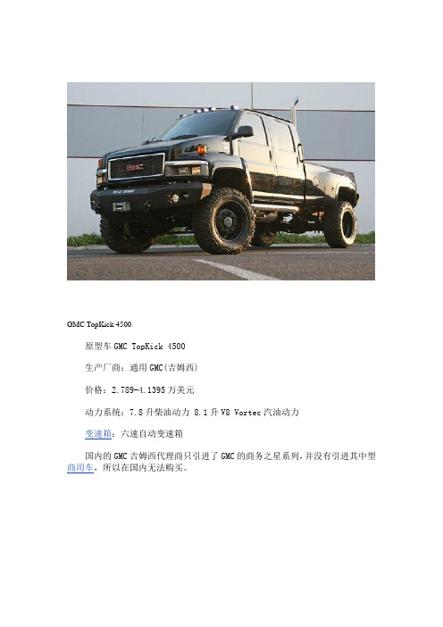
GMC TopKick 4500原型车GMC TopKick 4500生产厂商:通用GMC(吉姆西)价格:2.789-4.1395万美元动力系统:7.8升柴油动力 8.1升V8 Vortec汽油动力变速箱:六速自动变速箱国内的GMC吉姆西代理商只引进了GMC的商务之星系列,并没有引进其中型商用车,所以在国内无法购买。
GMC TopKick 4500回到上世纪80年代,铁皮最初是作为一辆小型货车,自那以后,就一直在改良提升。
毕竟,他是一名勇士博派,变形为雪佛兰Uplander将会很可笑。
这一最新的化身在成为人类的守卫者之前起初是作为一款震耳欲聋的GMC TopKick 敞蓬小货车出现的。
Topkick系列是通用旗下GMC分部开发的中型商用车,C4500是其入门型号,它提供单排座、双排座、房车、公共汽车等4种车身样式,并且有其余车身样式可改装。
发动机采用的是广泛应用在通用集团卡车中的8.1升V8 Vortec汽油发动机,最大功率325马力,最大扭矩约62公斤米。
另外一款发动机是6.6升Duramax涡轮增压柴油发动机,最大功率330马力,最大扭矩85公斤米。
售价2,7890-4,1395美元。
TopKick 4500不是一辆传统的消费者产品,而是一辆2吨型的中型卡车。
大家知道,这种类型的卡车背后有商业基础的支持,企业的名字就被钢印在门上。
然而,威斯康星州门罗的门罗设备公司已经建造了一个能够将TopKick改成敞蓬小货车的强大企业,同时该企业还为这些敞蓬小货车安装上了小型Sierra 3500 dually所使用的平板。
《变形金刚》这部影片的汽车部门开始时用两辆门罗公司改装的TopKick 4500 crew cab 4x4敞蓬小货车作为建造两辆铁皮的基础,为了其在银幕上更好看汽车部门还为它们用化妆品进行了涂抹。
冲着变形金刚的热潮,北美特殊车辆制造商MONROE TRUCK特别依照电影中TopKick 4500的造型,打造了专属的改装套件,以及舒适度调校让车迷可以过足电影瘾,也就是说你如果有一辆GMC TopKick 6500,那么恭喜你了,你完全可以按照电影中的铁皮形象进行改装.。
GK-4500型渗压计安装使用手册(REV J)
GK-4500 振弦式渗(扬)压计安装使用手册
3
2. 安装
2.1 初步检验
在验收时就应对渗压计读数进行检查和记录(详见第 3.1 节到 3.3 节关于读 数的说明) 。渗压计的内部有热敏电阻装置用在来测量温度(详见第 3.4 节的说 明) 。 每支仪器都提供了率定数据,包括在特定温度和气压之下的零读数。现场的 零读数要在压力的温度修正后应与工厂的读数相一致, 其差别在 20 个字之内。 制 造地海拔是+580 英尺。 1995 年 3 月 21 日之前, 工厂的气压读数已修正到海平面, 这个日期之后读数即代表绝对压力。 (气压随海拔的变化率是每 1000 英尺近似 0.5Psi) 。详见图 2-1 关于率定表的实例。
目
1. 2.Leabharlann 录3.4.
5.
工作原理 ..................................................................................................................2 安装 ..........................................................................................................................3 2.1 初步检验 ...........................................................................................................3 2.1.1 创建零读数 ............................................. 3 2.1.2 检查率定 ............................................... 4 2.2 在测压管或测井的安装 ...................................................................................5 2.3 在钻孔中的安装 ...............................................................................................6 A 类安装 ..................................................... 6 B 类安装 ..................................................... 6 2.4 在填土和坝体上的安装 ...................................................................................7 2.5 在软土中推挤或打桩的方式安装 ...................................................................8 2.6 过滤器的排气 ...................................................................................................9 2.6.1 低通气型过滤器,4500S 和 4500PN 型。 ..................... 9 2.6.2 4500S 型,可拆卸的陶瓷过滤器 ........................... 9 2.6.3 4500DP 型 ............................................. 10 2.7 4500H 型传感器 .............................................................................................10 2.8 接线和集线箱 .................................................................................................11 2.9 防雷保护 .........................................................................................................12 读数 ........................................................................................................................13 3.1 GK-401 振弦读数仪 .......................................................................................13 3.2 GK-403 读数仪操作 .......................................................................................13 3.3 温度测量 .........................................................................................................14 数据处理 ................................................................................................................14 4.1 压力计算 .........................................................................................................14 4.2 温度修正 .........................................................................................................15 4.3 气压修正(仅用于非通气型传感器) .........................................................16 4.3.1 通气型渗压计 .......................................... 17 4.4 环境因素 .........................................................................................................17 故障排除 ................................................................................................................18
现代汽车IONIQ_5_N_韩国驭电开跑

试车编号:No.2866HYUNDAIIONIQ 5N在此次现代汽车N 品牌IONIQ 5 N 韩国驾驭体验之旅中,我们深度体确保每一款N 品牌的量产车型都能完美传承N 品牌的三大核心高性能代表力作。
COVER STORY 封面故事现代汽车I O N I Q 5 N 刚刚在洛杉矶车展上斩获“2024世界年度性能车”大奖殊荣之后不久,我们就受邀来到韩国H M G D X 现代汽车集团驾驶体验中心,首次在赛道上亲身感受N 品牌首款量产高性能电动车I O N I Q 5 N 的独特魅力与卓越性能。
撰文:李耕现代汽车I O N I Q 5 N 韩国驭电开跑弯道电顽童的基因,更通过一系列专属技术调校,使其过弯性能达到了全新的水准。
在车身刚性部分,IONIQ 5 N新增42个增强焊接点,并优化了后备厢、电机、电池以及前后副车架的布局,进一步增强车身结构的稳定性和整体性能,确保了车辆在过弯时的稳定性。
不仅如此,IONIQ 5 N还对前后集成驱动桥进行了强化处理,使其能够承受更强大的电机扭矩。
与此同时,为了提升车辆转向时的响应和反馈,IONIQ 5 N对转向柱进行了特殊处理,除了提高转向比,还配备了经过特别调校的N齿条式电机驱动动力转向系统,大幅增强了转向扭矩反馈,带来了更直接和富有交互性的转向体验。
再搭配上专属的N Pedal(N 竞技踏板模式)功能,提供即时转向反馈和更强的油门响应,并利用减速产生的重量转移,大大优化了弯道驾驶体验。
为了提升驾驶乐趣,IONIQ 5 N配备了N Drift Optimize(N 漂移优化系统)电子控制技术,该功能可在驾驶过程中实现实时响应和输入,其集成的扭矩反冲漂移功能可模仿后驱燃油车的离合器反冲动作,特别适用需要快速启动漂移的驾驶场景。
HYUNDAIIONIQ 5 N车内增加了很多“N”元素,包括在前排整体式座椅靠背的前面和背面、前后门门槛处,方向盘上更有三处。
整车里里外外算下来,N标识不少于21个。
Lancer 冰淇淋机 4500系列安装说明书

6655 LANCER BLVD. • SAN ANTONIO, TEXAS 78219 USA• (210) 310-7000LINE MUST BE USED IF THE WATER SUPPLY CONTAINS ANY APPRECIABLE AMOUNT OF SILT, SAND, OR ANY OTHER DEBRIS. FAILURE TO DO SO CAN RESULT IN EQUIPMENT DAMAGE.FAILURE TO LIMIT WATER PRESSURE TO 50 PSI (3.52 KG/CM2) WILL RESULT IN IMPROPER PERFORMANCE OF THE DISPENSER - INSTALL WATER REGULATOR IF NECESSARY.THE WATER SUPPLY MUST BE PROTECTED BY MEANS OF AN AIR GAP, A BACKFLOW PREVENTION DEVICE (LOCATED UPSTREAM OF THE CO2 INJECTION SYSTEM) OR ANOTHER APPROVED METHOD TO COMPLY WITH NSF STANDARDS. A LEAKING INLET WATER CHECK V ALVE WILL ALLOW CARBONATED WATER TO FLOW BACK THROUGH THE PUMP (WHEN IT IS SHUT OFF), AND CONTAMINATE THE WATER SUPPLY. A BACKFLOW PREVENTION DEVICE MUST COMPLY WITH ASSE AND LOCAL STANDARDS. IT IS THE RESPONSIBILITY OF THE INSTALLER TO ENSURE COMPLIANCE.A SCREEN OF AT LEAST100 MESH [100 STRANDS PER 25MM (ONE INCH)] SHALL BE INSTALLED IMMEDIATELYUPSTREAM OF ALL CHECK V ALVE TYPE BACKFLOW PREVENTERS USED FOR WATER SUPPLY PROTECTION. THE SCREEN SHALL BE ACCESSIBLE AND REMOV ABLE FOR CLEANING OR REPLACEMENT.A FILTER IN THE WATER LINE MUST BE USED IF THE WATER SUPPLY CONTAINS ANY APPRECIABLE AMOUNT OF SILT,SAND, OR ANY OTHER DEBRIS. FAILURE TO DO SO CAN RESULT IN EQUIPMENT DAMAGE.DO NOT OPERATE CARBONATOR PUMP WITH WATER SUPPLY SHUT OFF.A.An adequate potable water supply must be provided. The water supply line must be at least a 3/8 inches (9.525 mm) pipe with aminimum of 20 PSI line pressure, but not exceeding a maximum of 50 PSI. Water pressure exceeding 50 PSI must be reduced to 50 PSI with a pressure regulator.1.Water pipe connections and fixtures directly connected to a potable water supply must all be sized, installed, and maintainedaccording to Federal, State, and Local laws.2.Off tastes and excessive silt, sand, or iron require that a water filter be installed in the water supplying the Carbonator. The waterfilter should be checked periodically, as required by local conditions.3.Do not connect to a heated (hot) water source or a water source supplying soft water. This will cause excessive foaming.B.The Carbonator Pump is equipped with a Strainer and a Tee on the outlet side for a plain water Valve (if required), but a water supplycontaining any appreciable quantity of silt, fine sand, or other debris requires a Filter ahead of the Unit. The Filter cartridge must be cleaned periodically, depending upon the condition of the water. Failure to do so may starve the Pump and cause it to burn out;thereby, voiding the equipment warranty.1.6INSTALLATION OF THE UNITA Inspect the counter location where the unit is to be installed. Verify that the counter is strong enough to safely support the weight ofthe unit being installed (see Section 1.3), after the cutout for the unit is made.B.Remove Splash Plate and Top Cover.C.Remove Cover Plate at rear of unit if not a “through the counter” installation.D.Connect soda and water supply lines to 3/8 inch barb fittings at the front of the unit. Check for leaks. (If dispenser is to operate withall soda valves, connect water line into one of the soda supply lines.)E.Connect syrup supply lines to the 3/8 inch barb inlet fittings at the front of the unit. Check for leaks.F.Install the ice bin drain hose; connect the 90° elbow or straight fitting underneath the unit’s base. The ice bin drain is located towardsthe front of the bin and slightly to the right. Screw the elbow or straight fitting into the cold plate; uncoil and connect the hose. Extend the hose to an open type drain.G.Connect the hose to the Drip Tray fitting, install the Drip Tray, and extend hose to open type drain.H.Both drain lines must be insulated with a closed cell insulation. Insulation must cover the entire length of the drain hose, includingfittings. The drain should be installed in such a manner that water does not collect in sags or other low points, as condensation will form.I.Install Cup Rest and Splash Plate.J.Connect Power Cord to grounded electrical outlet.K.Test Motor operation by pushing Ice Chute.L.Clean and sanitize dispenser (see Section 3).M.Fill unit approximately half full with ice. Push Chute and check for ice delivery.N.Finish filling the unit with ice and install Top Cover.O.Set brix ratio for beverage dispensing valves according to manufacturer’s instructions.1.7CONNECTING CO2WARNINGSCARBON DIOXIDE (CO2) DISPLACES OXYGEN. STRICT ATTENTION MUST BE OBSERVED IN THE PREVENTION OF CO2GAS LEAKS IN THE ENTIRE CO2AND SOFT DRINK SYSTEM. IF A CO2GAS LEAK IS SUSPECTED, IMMEDIATELY VENTILATE THE CONTAMINATED AREA BEFORE ATTEMPTING TO REPAIR THE LEAK.CO2IS A HEA VIER THAN AIR, COLORLESS, NONCOMBUSTIBLE GAS WITH A FAINTLY PUNGENT ODOR. HIGH PER-CENTAGES OF CO2MAY DISPLACE OXYGEN IN THE BLOOD, PROLONGED EXPOSURE TO CO2MAY BE HARMFUL.PERSONNEL EXPOSED TO HIGH CONCENTRATIONS OF CO2GAS WILL EXPERIENCE TREMORS WHICH ARE FOLLOWED RAPIDLY BY LOSS OF CONSCIOUSNESS AND SUFFOCATION.UNDER NO CIRCUMSTANCE SHOULD CO2PRESSURE EXCEED 80 PSI (5.6 KG/CM2). PRESSURE ABOVE THIS LIMIT WILL RESULT IN DAMAGE TO THE SYRUP PUMPS. SHOULD REMOTE SYRUP PUMPS FAIL TO OPERATE PROPERLY AT70 PSI (4.9 KG/CM2), THE CO2PRESSURE MAY BE REDUCED TO A MINIMUM PRESSURE OF60 PSI (4.2 KG/CM2), BUT NO LOWER. TO A VOID POSSIBLE PERSONAL INJURY OR PROPERTY DAMAGE, DO NOT ATTEMPT TO REMOVEIBD22, 28-0255/06IBD30, 28-0255/06。
allison 4500编号的意思
allison 4500编号的意思Allison 4500是一种经典的自动变速器型号,属于Allison Transmission公司生产的重型商用车辆变速器系列之一。
Allison Transmission是全球领先的自动变速器制造商,其产品广泛应用于卡车、公交车、工程车等各类商用车辆中。
Allison 4500变速器是专为高扭矩和高功率应用而设计的,适用于重型卡车和大型工程车辆。
该型号变速器采用了一系列先进的技术和创新设计,以提供卓越的性能、可靠性和耐久性。
以下是Allison 4500编号的一些具体含义和解释:1. 车型适应性:4500表示该变速器适用于重型车辆,可以处理高扭矩和高功率输出。
它通常与大型柴油引擎配合使用,以满足重载运输和高强度工作的需求。
2. 配置和功能:4500还可以包含其他数字和字母组合,用于进一步描述该变速器的配置和功能。
例如,4500 RDS表示该变速器具有辅助驾驶器启动(Retarder Drive System)功能,可提供额外的制动能力。
3. 挡位数量:4500编号还可以指示变速器的挡位数量。
Allison 4500通常具有4个或5个前进挡位和1个或2个后退挡位,以适应不同的驾驶和工作条件。
4. 控制系统:Allison 4500变速器还可以与各种控制系统集成,如电子控制单元(ECU)和车辆总线系统。
这些系统能够监测和优化变速器的性能,并提供更高的驾驶舒适性和可操作性。
总的来说,Allison 4500编号代表了一种适用于重型商用车辆的高性能自动变速器,具有强大的扭矩和功率输出能力,以及先进的控制系统和功能。
它是商用车辆行业中备受信赖和广泛应用的变速器型号之一。
青海省科学技术厅关于下达青海省二〇二〇年科技计划项目的通知
青海省科学技术厅关于下达青海省二〇二〇年科技计
划项目的通知
文章属性
•【制定机关】青海省科学技术厅
•【公布日期】2020.03.02
•【字号】青科发规〔2020〕20号
•【施行日期】2020.03.02
•【效力等级】地方规范性文件
•【时效性】现行有效
•【主题分类】科技计划,科技经费与财务
正文
青海省科学技术厅关于下达青海省二〇二〇年科技计划项目
的通知
各有关单位:
现将《青海省二〇二〇年结转科技项目经费计划》、《青海省二〇二〇年新开科技计划项目》下达给你们,本批计划包括科技项目264项,本年度拟资助经费46461万元。
其中,结转科技项目109项,当年资助15907.35万元;新开科技项目155项,当年资助30553.65万元。
请接此通知后,按已下达的经费预算完成项目合同书签定,加快推进项目的组织实施工作。
附件:1_青海省二〇二〇年结转科技项目经费计划.doc
2_青海省二〇二〇年新开科技计划项目.docx
2020年3月2日附件
1.青海省二〇二〇年结转科技项目经费计划。
PZ-CNC4500说明书
PZ3500 系列机型 75A
PZ4500 系列机型 75A
PZ6500 系列机型 75A
c. 马达电力需求(单位:KW)
9
TEL:+86-757-86283358
HTTP ://
使用说明书
项目 三轴马达 主轴马达(60 分) 干式吹气 luen 润滑 旋转刀库马达 4.5 空气压缩器
赖安全装置,为了确保安全,操作者必须在操作机器前细读操作手册且完全了解特殊的 预防措施。 B. C. 当按下操作面板上的能源开关钮时,需确实检查“READY”灯是否有亮起。 在启动机器后, 或经过长时间的休息(如隔天一早), 请先开启电源最少运转 30 分钟 ,
以便润滑油可布满至整个滑动面。然后在自动模式下以 50%或 30%的速度运转所有轴向 最少 10~20 分。请检查移动与旋转是否正常。 D. E. F. 检查油位及所有系统是否正常。 检查刀具、模块及工作是否正确。 在真正加工前请先试转。 5.操作机器前之特别注意事项 A. 确定所有的操作门是关闭的。
PZ3500 系列机型 4.5 7.5 0.05 0.125 0.25
PZ4500 系列机型 4.5 7.5 0.05 0.125 0.25
PZ6500 系列机型 4.5 7.5 0.05 0.125 0.25
空压机一定要选择用能够充分提供机台所须之充分气量,若气压不够容易造成刀库换刀中 断,增压缸压力不足等问题产生,且要定时排除空压缸内之积水。 注意:只能用清洁又干净的气供应机械使用,假若空气中含有水气喷出,则容易造成气动组 件故障,及铁质部分生锈。
10. 确认机器及控制系统无故障。 11. 确认指令程序手册皆完全了解。 12. 在启动开关前确认开关是否正确,不要突然碰触会引起故障或危险的开关。 13. 不要穿戴手套启动开关,那会引起故障甚至危险。 14. 不要以潮湿的手作业,那将引起电击。 15. 在电源没有时要立即关掉主要断路器。 16. 在无电源或能源中断后必须回到三轴原点模式。 17. 不要改变参数或其它设定,除非必要,如果一定要改则需记录原始的数值,以 便需要时能回到原始的设定。 18. 在重新装置保险丝或电气零件前,关机并根据之后的步骤操作。 19. 极限开关,近接开关,连接装置和其它装置不应被拆卸或更改。 20. 务必告知机器型号及机号,如此我们才能够尽速处理你的需求。 21. 为避免中断,机器应安置于远离高频波及焊接机器。 22. 为避免中断及电击,接地线需连接于地面上之接地板。 23. 安装需在室温 20℃~30℃。 24. 不要站在金属板的零件上以免破坏或使自己受到伤害。 25. 操作人员需受到专业知识训练的认证。 26. 戴手套去关铁屑输送机是很危险的。 27. 当有噪音及打雷时停止机器,如果机器因打雷受损,那么客户将为所有产生的 后果负责。 2.4、电源供应安装:
江森自控METASYS设计手册

第九章� 应用实例
�
9.1� 冷冻系统监控
�
9.2� 热交换站监控
�
9.3� 新风机组监控
�
9.4� 空调机组监控
技术手册说明 *由于我们的产品在不断地改变�本技术手册中的技术规格和信息的改变恕不另行通知�具体选型以 实际提供的技术参数为准。JOHNSON CONTROLS为任何误用或歧义造成的偶然或必然的损害不承担 任何责任。
注�电机启动盘只包括开关、继电器、接线端子�它的系统非工作时间实际上趋近为0。
AVAILABILITY 99.9964% 99.9971% 99.9971% 100%
Metasys�ADS 系统结构
概述
� 整个Metasys ADS系统由操作 站、网络控制引擎、现场控制器组 成�一个典型的系统架构如下图所 示。
以上等式是可靠性的定义标准。在这里非工作时间是指维 修和返修产品所需要的平均时间。这个平均时间通常称为 平均修复时间�包括预计的时间及不可预计的时间。在正 常的情况下�不论白天黑夜�我们的紧急反应时间不超过 四个小时。
系统可靠性也被表示为平均修复时间�MTTR�和平均故障 间隔时间�MTBF�。平均故障间隔时间是指系统可靠性的 一个衡量尺度�平均修复时间是系统可维护性的一个衡量 尺度。他们的关系如下� 系统可靠性=平均故障间隔时间/�平均故障间隔时间+平 均修复时间�
4500系列艾里逊液力变速箱防爆改造技术

4500系列艾里逊液力变速箱防爆改造技术TENG Pai;DENG Zhongbin;DING Hui;XIANG Dan;WU Jian;DU Yuwen【摘要】目前,中海油在渤海海域油田配置有ALLISON 750系列液力自动变速箱40余台,主要应用于钻井与修井等平台驱动泥浆泵、绞车等设备.美国艾里逊公司已停止生产ALLISON 750系列液力变速箱并停止相应配件服务.为保障现有的海洋修井机继续正常运行,在4500系列艾里逊液力变速箱替代应用技术研究的基础上,提出了针对Allison第5代4500 OFS变速箱电控系统防爆改造设计方案,对其电控部分予以2区防爆改造处理,以满足油田作业区域对海洋修井机设备防爆的要求,方案实施结果表明,采取防爆改造技术可实现对机械式Allison 750系列变速箱的替代应用.【期刊名称】《天津科技》【年(卷),期】2019(046)001【总页数】4页(P42-45)【关键词】海洋修井机;变速箱;电控系统;防爆改造;替代应用【作者】TENG Pai;DENG Zhongbin;DING Hui;XIANG Dan;WU Jian;DU Yuwen【作者单位】;;;;;【正文语种】中文【中图分类】TE920 引言由于目前渤海区域海洋修井机上使用的美国艾里逊公司的Allison 750变速箱使用时间大多超过20年,且Allison 750变速箱停产时间超过10年,已经没有原厂的变速箱配件供应。
为保障现有的海洋修井机继续正常运行,在4500系列艾里逊液力变速箱替代应用技术研究[1]基础上,需采用Allison第5代4500 OFS电控变速箱,对其电控部分做2区防爆改造处理[2],来替代机械式的Allison750变速箱。
为满足Allison 4500 OFS变速箱在海洋修井机钻台2区防爆运行要求,基于Allison 4500 OFS变速箱控制系统的结构和功能特点,需要进行如下方面的防爆改造:①Allison 4500 OFS变速箱本体防爆改造。
klinger sil c-4500

KLINGERSIL ®C-4500Carbon fibres and special heat resistant additivesbonded with NBR.A superior performance product designed for use with strongly alkaline media and steamin the chemical industry.KLINGER – The global leader in static sealingA Hightech Fibre Material –ideal forstrong alkali mediaand steamNanjing Ruipingde Electromechanical Equipment Co., LtdRoom 219,No. 35, Puzhou Road, Riverine Industrial Zone, Pukou District, Nanjing,China Tel.+86(0)25-58731856 Fax+86(0)25-58748806KLINGERSIL C-4500®Maximum permissible surface pressure σBO under operating conditions acc. DIN 28090 – 1 The maximum surface pressure under operating conditions is the maximum allowable surface pressure on the effective gasket area under service conditions that can be applied to the gasket before unacceptable relaxation of the flanged joint occurs and/or the gaskets are destroyed.Min. surface pressure σVUfor tightness classesL= 1.0, L= 0.1 and L= 0.01in accordance to DIN 28090The minimum surface pressure is theminimum surface pressure that shouldbe applied to the gasket to achievethe necessary tightness requirements.The value must be sufficient tocompress the material into the flangeimperfections, reduce the materialsMinimum surface pressure σBUfor tightness class L= 0.1The three dimensional diagram belowdescribes the behaviour of 2 mmgasket material with respect to theminimum surface pressure to achievea tightness class of L = 0.1 under awide range of temperatures andinternal pressures. It clearly showsthat the minimum surface pressuredecreases at elevated temperatures –0205040307060801020304050L0.5mm1.0mm1.5 mm2.0m m3.0 m m205040307060801020304050L0.5mm1.0mm1.5mm2.0m m3.0 m mKLINGERSIL C-4500®Tightness class L= 0.1 allows a maximum leakage of 0.1 mg nitrogen per second per meterof gasket length (mg/s x m)Flanged joint integrityImportant points to be observed With heightened awareness of safety and environmental issues, reducing leaks from flanged assemblies has become a major priority for industry.It is therefore important for companies who use gaskets to choose the correct material for the job and install and maintain it correctly to ensure optimum performance.A flanged joint will remain tight as long as the surface pressure in service is higher than the minimum surface pressure required to achieve the necessary levels of tightness but is lower than the maximum permissible surface pressure.But increasingly high demands on the tightness requirements for flanged joints (e.g. Tightness class L 0.1 in accordance with DIN 28090)necessitate the application of high loads on the gasket material in order to meet these stringent requirements. If the gasket is to be subjected to non-static loading and stress fluctuations due to temperature and pressure cycling, it is advisable to select a gasket material which is less prone to embrittlement with increasing temperatures (e.g.KLINGERgraphite laminate,KLINGERtop-chem or KLINGERtop-sil). In cyclic loading conditions we recommend a minimum surface stress of 30 MPa and that the gasket should be as thin as is practicable.For safety reasons never re-use gaskets.Gasket load 15 MPaGasket load 20 MPaGasket load 35 MPaL e a k m g /(s m )L e a k m g /(s m )L e a k m g /(s m )L e a k m g /(s m )L e a k m g /(s m )L e a k m g /(s m )High temperature tightness High temperature tightness is measured by means of the Klinger Hot Compression test under defined constant gasket load and temperature with increasing internal pressures using nitrogen as test fluid.Stabilisation time for each reading is two hours and a new test specimen is used for every gasket load and temperature.The tightness is analysed with a massflow meter. The pressure is controlled by pressure controller.The following guidelines are designed to ensure the optimum performance of our gasket materials: 1. Choosing the gasketThere are many factors which must be taken into account when choosing a gasket material for a given appli-cation including temperature, pressure and chemical compatibility. Please refer to the information given in our brochure or, for advice to our software program KLINGER®expert. If you have any questions regarding the suitability of material for a given application please contact Klinger Technical Department.2. Gasket thicknessThe gasket should be as thin as technically practical. To ensure optimum performance a minimum thickness/width ratio of 1/5 is re-quired (ideally 1/10).3. Flange conditionEnsure all remains of old gasket materials are removed and the flanges are clean, in good condition and parallel.4. Gasket compoundsEnsure all gaskets are installed ina dry state, the use of gasket compounds is not recommendedas this has a detrimental effect on the stability and load bearing characteristics of the material. In its uncompressed form the gasket can absorb liquid, and this may lead to failure of the gasket in service. To aid gasket removal Klinger materials are furnished with a non sticking finish.In difficult installation conditions, seperating agents such as dry sprays based on molybdenum sulphide or PTFE e.g. KLINGERflon spray, may be used, but only in minimal quantities. Make sure that the solvents and propellants are completely evaporated. Installation instructions 5. Gasket DimensionsEnsure gasket dimensions are correct.The gasket should not intrude into thebore of the pipework and should beinstalled centrally.6. BoltingWire brush stud/bolts and nuts(if necessary) to remove any dirt onthe threads. Ensure that the nuts canrun freely down the thread before use.Apply lubricant to the bolt andto the nut threads as well as to theface of the nut to reduce friction whentightening. We recommend the useof a bolt lubricant which ensures afriction coefficient of between 0.10to 0.14.7. Joint AssemblyIt is recommended that the bolts aretightened using a controlled methodsuch as torque or tension, this willlead to greater accuracy andconsistency than using conventionalmethods of tightening. If using atorque wrench, ensure that it isaccurately calibrated.For torque settings please referto the KLINGER®expert or contact ourTechnical Department which will behappy to assist youCarefully fit the gasket intoposition taking care not to damagethe gasket surface.When torquing, tighten bolts inthree stages to the required torque asfollows:Finger tighten nuts. Carry outtightening, making at least threecomplete diagonal tighteningsequences i.e. 30%, 60% and 100%of final torque value. Continue withone final pass – torquing thebolts/studs in a clockwise sequence.8. RetighteningProvided that the above guidelinesare followed retightening of thegasket after joint assembly shouldnot be necessary.If retightening is considerednecessary, then this should only beperformed at ambient temperaturebefore or during the first start-upphase of the pipeline or plant.Retightening of compressed fibregaskets at higher operatingtemperatures and longer operatingtimes may lead to a failure of thegasket connection and possible blowout.9. Re-useFor safety reasons never re-use agasket.Powerful sealing calculationwith online help onCD-ROMT echnical data■UsesHigh pressure gasket for special applications. Suitable for use with strong alkali medias and steam at higher temperatures as well as to oils,gases, salt solutions, fuels, alcohols,organic and inorganic acids,hydrocarbons, lubricants andrefrigerants. Premium material grade with very high stress retention.■ Dimensionsof the standard sheets Sizes:1000 x 1500mm,2000 x 1500mm.Thicknesses:0.5mm, 1.0mm, 1.5mm,2.0mm, 3.0mm;other thicknesses and sizes on request.Tolerances:thickness ±10%, length ±50mm,width ±50mm.■ SurfacesKLINGERSIL ®gasket materials are generally furnished with surfaces of low adhesion. On request, graphite facings and other surface finishes on one or both sides are also available. ■ Function and durabilityThe performance and service life of KLINGER gaskets depend in large measure on proper storage and fitting, factors beyond the manu-factor’s control. We can, however,vouch for the excellent quality of our products.With this in mind, please also observe our installation instructions.■ Tests and approvalsFire safe according API SPEC 6 FA.BAM approval in accordance with UVV 28, oxygen( VGB 62)tested up to 100 bar and 85°C.Approved for gas supply in accordance with DIN 3535/6.DIN - DVGW permit NG 5123AN0539.ÖVGW permit, KTW recommended Lab. National d`Essais 105.097Germanischer Lloyd.Meets the technical requirements of BS 7531:2006 Grade AX.TA Luft ( Clean air ) approval,tested in accordance with VDI 2440 at 250°C.Nanjing Ruipingde Electromechanical Equipment Co., LtdRoom 219,No. 35, Puzhou Road, Riverine Industrial Zone, Pukou District, Nanjing,China Tel.+86(0)25-58731856 Fax+86(0)25-58748806。
中东版陆巡4500大保养作业
中东版陆巡4500大保养作业中东版陆巡4500是一款专为中东市场设计的越野车型,具有出色的越野性能和可靠的动力系统。
为了保持车辆的良好状态和延长使用寿命,定期的大保养是必不可少的。
本文将介绍中东版陆巡4500的大保养作业内容和步骤。
一、更换机油和机滤机油是发动机正常运转所必需的润滑剂,定期更换机油能有效保护发动机,并提升其工作效率。
在大保养时,应将旧机油彻底排干,并安装新的合适型号的机油,并同时更换机油滤清器。
二、更换空气滤清器空气滤清器的作用是过滤空气中的杂质,防止进入发动机内部,保护发动机的正常运转。
在大保养时,应将旧空气滤清器取下,并安装全新的空气滤清器。
三、更换燃油滤清器燃油滤清器能够过滤燃油中的杂质和水分,防止其进入发动机燃烧室,保护燃油系统的正常运行。
在大保养时,应将旧燃油滤清器取下,并安装新的燃油滤清器。
四、更换火花塞火花塞是发动机点火系统中的关键部件,能够引燃混合气体,驱动发动机工作。
定期更换火花塞能够保持发动机的正常运行和燃烧效率。
在大保养时,应将旧火花塞取下,并安装新的适配型号的火花塞。
五、更换传动系统油传动系统油是保证变速器正常工作的重要润滑剂,定期更换传动系统油能够延长变速器的使用寿命和提升换挡顺畅度。
在大保养时,应将旧传动系统油彻底排干,并加注新的适用型号的传动系统油。
六、检查制动系统制动系统是车辆行驶安全的关键部件,定期检查制动片、制动盘和制动液的磨损情况,并及时更换,能够保证制动系统的正常工作。
七、检查悬挂系统悬挂系统对于车辆的稳定性和行驶舒适性有着重要影响。
大保养时,应检查悬挂系统的各个部件,包括悬挂弹簧、减震器等,确保其工作正常。
八、检查电池和电路系统电池是车辆电力系统的重要组成部分,定期检查电池的电量和电路系统的工作情况,确保电力系统正常运行。
九、检查轮胎和转向系统轮胎是车辆与地面直接接触的部分,定期检查轮胎的磨损情况和气压,确保轮胎的正常使用。
同时,检查转向系统的工作情况,保证转向灵活准确。
液质AB4500操作规程

一、开关机A A 、开机1.打开UPS电源,打开氮气发生器(气瓶),确认Curtain gas的输入压力为0.4MPa,gas1/2为0.7MPa,exhuast为0.4MPa。
2.打开机械泵电源开关(5500系列直接打开质谱主机电源,仪器自动启动机械泵)3.等机械泵工作至少30min5.打开质谱主机电源开关6.过夜抽真空B B 、关机1.停止输液:关停针泵或液相泵,或断开输液管线(一般质谱主机Standby后液相系统也自动待机,输液泵自动关停,但建议操作人员再次确认,必须保证没有任何液体再泵入质谱)2.使仪器待机,并灭活配置2.关闭质谱仪主机电源开关(5500系列只需按下电源开关旁的VENT按键排放真空)3.机械泵继续工作至少30min4.关闭机械泵上的电源开关(5500系列会自动关停机械泵,待机械泵停止后即可关闭5500系列主机上的电源开关)5.关闭气体发生器或气瓶二. 仪器校准与调谐本节包括如何在Analyst 软件中进行手动质量校准,一般仪器在开关机后才需要做调谐或每个季度例行调谐。
1 1 、打开analyst软件,双击Hardware Configure,在硬件配置Hardware Configure 菜单下单击ma ssSpecOnly ( 只连质谱机),单击Active profile激活仪器。
硬件配置表中massSpecOnly 出现绿勾后,表示质谱仪主机与计算机通讯正常,关闭Hardware Configuration Editor。
3、双击左边工具菜单Navigation Bar 中的Manual Tuning,打开一个空白质谱参数设置及运行窗口,进入手动调谐模式:4、在project 工具条中选择installation- -开头的项目文件夹5、点击File open6、选择Acquisition Method 打开四极杆校准方法文件列表(如:Q1PosPPG.dam,Q1NegPPG.dam,Q3PosPPG.dam,Q3NegPPG.dam 方法文件,文件名有可能不同)。
Sperry Marine NAVIPILOT 4500N使用手册说明书

NAVIPILOT 4500NNetworked, adaptive and self-tuning Heading Control SystemNAVIPILOT 4500N is Sperry Marine’s new networked, self-adaptive heading control system that combines industry-leading performance with easier deployment and operation. It keeps your vessel more efficiently on course, reduces fuel consumption,emissions and workload on the bridge.With a colour touchscreen, it’s intuitiveto use and heading control functionalityis safely operated with a dial wheel andbuttons to avoid unintended changes.NAVIPILOT 4500N still delivers theheading control performance thatSperry Marine is renowned for, to keepyour vessel more efficiently on course.Keep your vessel more efficiently on course, reduce fuelconsumption, emissions and workload on the bridgeStay compliant• T ype approved to applicableMED standardImprove ease of use• I ntuitive 7” colour touch screenfor improved readability• Swipe between screens forimproved accessibility of settings• H armonized alarm managementto reduce frequency and operatorworkload, with guidance onrequired actionIncrease reliability• S elf-monitors for faults andsystem configuration via integrateddiagnostics for efficient supportOptimise operationalschedule• A daptive and self-tuning system thatcontinuously monitors and optimisesheading control performance to keepthe vessel more efficiently on courseReduce through-life costs• E asy to install with reducedcomponents, standard networkcabling and connectionsImprove flexibility• H eading control available as astandalone system or additional toNAVIGUIDE 4000 manual steeringsystem, for new builds or retrofitsReduce emissions• I ndustry-leading heading controlperformance with minimisedrudder movement required duringmanoeuvres, less force back,reduced need for propulsionenergy and less fuel consumption The NAVIPILOT 4500N has a continuous self-tuning adaptation for accurate steering and efficient fuelconsumption which enables the system to monitor performance and to automatically adjust rudder gainand counter rudder settings as needed, to keep the tuning optimized even if the vessel behavior is affectedby changes in loading and trim or by changing weather conditions.• A ll vessels have unique behaviour eventhose of the same design• T rim changes during voyage due to fuelusage changing weight of the vesselSelf-tuning fully adaptive feature adjusting to the vessel conditionReal-time self-tuning adaption for most accurate steering and efficientconsumption despite external and internal factors:• D ifferent cargo loading parameters fromone voyage to the next• L onger term changes in behaviour asthe vessel agesIntroduction to the NAVIPILOT 4500N new features on the touch displayKeep an eye on the main display indicating the actual heading from GYRO, the selected heading, as well as Autopilot active status.Easy access to the Autopilot control parameters without losing sight of the essential heading control information thanks to the split screen approach. Change your parameters in the Home and Dimming menus. If alerts are present in the system they will bedisplayed here automatically, including comprehensive operator guidance.Safety relevant functionality (eg.: changing headings) accessible by buttons and wheel. For easy Sperry Marine was one of the first companies to design and develop an autopilot with the aim of increasing profits by reducing the running costs of the ship using a fully self-tuning adaptive headingcontrol system. The ultimate version with new modern design provides additional ease of use to the crew whilst permanently indicate all information required by contemporary navigation demands:General integration optionsCombined with our Fiber Optic Gyro Compasses, the autopilot will be provided with the most stable and accurate heading data available on the market, meaning the autopilot does not need to over-correct. With the result of an overall reduction in rudder movements.VisionMaster / ECDISNAVIPILOT 4500N can be integrated with our VisionMaster ECDIS for advanced Track Control functionality, according to applicable MED standards:- Enhance safety and reduce operator workload with pre-programmed routes for repetitive courses- Simplify operations on more complex voyages with multiple waypoints or lots of manoeuvres- Reduce fuel consumption further with enhanced voyage planning that incorporates weather and sea conditionsNAVIGUIDE 4000 steering control systemNAVIPILOT 4500N can be integrated with our versatile manual steering control system NAVIGUIDE 4000 that provides all required manual steering modes. NAVIGUIDE 4000 can be interfaced with a wide range of steering gears and can thus be adapted to customer needs.The complete system can be easily used in any new build as an integral part of our Integrated Bridge System offering or in in retrofits to enhance our existing system or any third party’s systems.Our NAVIPILOT 4500N can be used on any kind of vessels, of all size and for all type of operations.Suitable for every operating scenarioNAVIGAT 2500Integrate with our NAVIGAT 2500fiber optic gyro compasses foreven higher system performanceand efficiency.NAVIGAT 200Providing more redundancywith our Network HeadingManagement System.VisionMaster IntegratedBridge SystemThe intelligent bridge forthe connected ship.NAVIGAT 3500Adding highest heading accuracyand motion reference data toyour bridge, especially whensailing in high lattitude. VisionMaster ECDISC reate a Track Control System throughintegration of NAVIPILOT 4500N withVisionMaster ECDIS to automatetrack keeping.NAVIGAT 100Single gyro headinginput compliance.You may also be interested in:Global Service and SupportSperry Marine provides service and support on a 24/365 basis at every major port worldwide, at anchor, offshore and at sea.All Marine Service Engineers are all certified to ensure they install, maintain and repair our products to the industry’s highest standards on a consistent global basis. Please see /services for full details of all our service locations.Find out morePlease visit for more information on Sperry Marine’s complete range of products and services.If you would like a quotation, please email sales@.BR-78/EXP-SD-2023-680。
- 1、下载文档前请自行甄别文档内容的完整性,平台不提供额外的编辑、内容补充、找答案等附加服务。
- 2、"仅部分预览"的文档,不可在线预览部分如存在完整性等问题,可反馈申请退款(可完整预览的文档不适用该条件!)。
- 3、如文档侵犯您的权益,请联系客服反馈,我们会尽快为您处理(人工客服工作时间:9:00-18:30)。
®Kestrel 4500 手持式风速仪(可测风向)
z
z z
z z z z
NK4500可测量参数: z z
z z z z z
z NK4500 特点: z 多功能
三行图表显示 可存储1400个数据
z 最小/最大/平均风速 z 用户可定义屏幕 小巧、坚固耐用 高精度轴承
z 操作范围广 z 叶轮可更换 z
高灵敏度温度传感器 背光显示
草绿色版本采用红色背景光,可提供照明 z 可选择语言 z 采用2个AAA 电池供电
数据可上传至电脑 风速
z 温度 z 侧风 顺风/逆风 温度
风寒 z 相对湿度 z 热度指数
露点温度
湿球温度 z 大气压 z 海拔高度
密度高度 时间/日期
Kestrel 4500具有Kestrel 4000的所有性能,能够
精确测量风速、温度、相对湿度、大气压和其他参数。
另外,Kestrel 4500具有一个内置的数字指南针,能够测
量和显示风向值。
当设定一个参照物时,Kestrel 4500能够自动计算侧
风、顺风和逆风风速,如果将其和Kestrel 风向标装置组
合,就可以在数秒内建立一个记录气象数据的小型气象
站。
Kestrel 4500是旋转风杯式风速仪,体积小巧,方便携带。
采用高精度轴承,轻量叶轮,可精确测量风速值,
即便是在风速很小(低至0.3m/s )的情况下。
如果叶轮损坏,可更换。
Kestrel 4500还可根据各传感器测量数据来计算出风寒指数、热度指数、露点温度、湿球温度和密度高度。
风寒是人类对风速和低温的一种感觉温度,风速越大,人类感觉温度越低;热度指数是人类对温度和相对湿度 的一种感觉温度,相对湿度越高,人类感觉温度越高;露点温度指空气在水汽含量和气压都不改变的条件下,冷却到饱和时的温度;密度高度是将气压高度值对温度校验后的高度。
Kestrel 4500采用2节AAA 电池来供电,可更换,具有2种省电模式来延长电池寿命。
可选语言:英语、法语、意大利语、西班牙语和德语。
Kestrel ®4500 手持式风速仪(可测风向)
产品规格 尺寸127mm×45mm×28mm 重量
102g 颈带绳
0.2m 和0.5m 物理 外壳颜色
黄色、草绿色 显示类型
点矩阵LCD ,场致(EL )发光背光 显示器更新
1秒 数据采集2秒到12小时之间,可调;图表可显示1400个数据点;可手动或自动采
集数据,数据可上传至电脑。
风速(当前值、最大/最小值、平均值)
风向 露点温度
侧风 大气压
顺风/逆风 海拔高度
温度 密度高度
风寒 湿球温度
相对湿度 数字指南针
可测量参数热度指数 时间和日期
风速单位Kt, m/s, km/h, mph, ft/min, Beaufort force(B)
风向单位°
温度单位℃, ℉
气压单位mBar, inHg, hPa, psi
海拔单位m, ft
显示 时间和日期显示dd/mm/yy, mm/dd/yy, 12 hour, 24 hour
操作范围0.4~ 60m/s (0.8~ 135mph )
精度范围0.4~ 40m/s (0.8~ 89mph )
精度读数的±3%或者 ±0.1m/s
校准漂移小于1% (7m/s 下操作100小时后)
风速 分辨率0.1kt, m/s, km/h, mph 。
操作范围360°
精度范围0~ 360°
精度±5°
风向 分辨率1°
操作范围-45~ +125℃
精度范围-29~ +70℃
精度±1.0℃
分辨率0.1℃
温度 风寒精度±1℃
操作范围0%~ 100%
精度范围5%~ 95%
精度±3%
分辨率0.1%
相对湿度 校准偏移±2%(使用24个月后)
操作范围10~ 1100mBar (25℃)
精度范围750~ 1100mBar (25℃)
精度±1.5mBar
分辨率0.1mBar
大气压 校准偏移典型 每年±1mBar
操作范围-2000~ +9000m
精度范围-2000~ +6000m
精度±15m
性能 海拔高度 分辨率1m
叶轮直径25mm ,高精度叶轮和轴承,用户可更换叶轮
温度传感器密封、绝热、高精度
相对湿度传感器电容式高分子传感器,安装在外面的薄壁电离室
传感器 大气压传感器单片硅材料气压传感器
防潮等级IP67
震动经过落地试验,抗震性MIL-STD-810F
温度操作范围:-10~ +55℃;存储温度:-30~ +60℃
环境 电磁兼容性(EMC )CE
电池2节AAA 碱性电池,用户可更换;电池寿命平均为400小时。
自动关机可设置为15分钟或60分钟后自动关机
校准风速、温度、大气压和相对湿度出厂已经校准;每一个Kestrel 风速仪都具有一个COC 认证证书
其他
保证5年。
