ESB33153中文资料
维沙亚高抗性 高压金属玻璃带领导电阻说明书
VR25000003303JA 100VR37000003904JA100VR25000008204JA100VR37000002005FA100VR37000002204FA100VR25, VR37, VR68Vishay BCcomponentsHigh Ohmic / High Voltage Metal Glaze Leaded ResistorsDESIGN SUPPORT TOOLSA metal glazed film is deposited on a high grade ceramic body. After a helical groove has been cut in the resistive layer, tinned electrolytic copper wires are welded to the end-caps. The resistors are coated with a light blue lacquer which provides electrical, mechanical, and climatic protection.FEATURES•UL Approved (UL1676, file no: E171160)•Meet the safety requirements of:-IEC 60065-DIN EN 60065-VDE 0860-CQC (China)•AEC-Q200 qualified (VR25, VR37)•High pulse loading capability (maximum 10 kV)•Radial version available for VR25•Material categorization: for definitions of compliance please see /doc?99912APPLICATIONS•Where high resistance, high stability, and high reliability at high voltage are required •High humidity environment •White goods •Power supplies •Automotive electronicsNote(1)Ohmic values (other than resistance range) are available on requestTECHNICAL SPECIFICATIONSDESCRIPTION VR25VR37VR68Imperial size 020*********Resistance range (1)100 k Ω to 22 M Ω100 k Ω to 33 M Ω100 k Ω to 68 M ΩResistance tolerance ± 10 %; ± 5 %; ± 1 %Temperature coefficient ≤ ± 200 ppm/KRated dissipation, P 700.25 W 0.5 W 1.0 W Operating voltage, U max. AC/DC 1600 V 3500 V 10 000 V Operating temperature range -55 °C to +155 °CPeak permissible film temperature 155 °C Thermal resistance (R th )140 K/W 120 K/W70 K/W Insulation voltage:1 min.; U ins700 V Maximum noise (white noise)5 μV/V 2.5 μV/V 2.5 μV/V Max. resistance change atrated dissipation for resistance range, |∆R /R | max., after 1000 h1.5 %1.5 %1.5 %SAFETY REQUIREMENTS AND QUALIFICATIONSDESCRIPTIONVR25, VR37VR37VR68Safety requirements / qualifications AEC-Q200UL1676 qualification (file no: E171160)for ohmic range 510 k Ω to 11 M Ω;DIN EN 60065 (VDE 0860): 2015; clause 14.2 a);EN 60065: 2014IEC 60065: clause 14.2 a)CQCVR25, VR37, VR68Vishay BCcomponentsNote(1)See table “Temperature Coefficient and Resistance Range” for selecting correct ohmic value - tolerance combinationTEMPERATURE COEFFICIENT AND RESISTANCE RANGETYPE TCRTOLERANCERESISTANCE E-SERIES VR25≤ ± 200 ppm/K± 1 %100 k Ω to 15 M ΩE24; E96± 5 %100 k Ω to 22 M ΩE24; E96± 10 %15 M Ω to 22 M ΩE24VR37± 1 %100 k Ω to 33 M ΩE24; E96± 5 %100 k Ω to 33 M ΩE24VR68± 1 %100 k Ω to 68 M ΩE24; E96± 5 %100 k Ω to 68 M ΩE24PART NUMBER AND PRODUCT DESCRIPTIONPART NUMBER: VR25000001003FA100TYPE / SIZE VARIANT TCR RESISTANCE TOLERANCE (1)PACKAGINGSPECIAL VR25000 = VR25VR37000 = VR37VR68000 = VR680 = neutral0 = standard3 digit value 1 digit multiplier MULTIPLIER 0 = *1001 = *1012 = *1023 = *1034 = *1045 = *1056 = *106F = ± 1 %J = ± 5 %K = ± 10 %A1AC A5RD R5N400 = standardPRODUCT DESCRIPTION: VR25 1 % A1 100KVR25 1 %A1100K TYPE / SIZETOLERANCE PACKAGINGRESISTANCE VR25VR37VR68± 1 %± 5 %± 10 %A1AC A5RD R5N4100K = 100 k Ω15M = 15 M ΩPACKAGINGTYPECODE QUANTITY PACKAGING STYLEWIDTH PITCH DIMENSIONS VR25A11000Taped according to IEC 60286-1 fan-folded in a box 53 mm 5 mm 75 mm x 31 mm x 260 mm A5500053 mm 5 mm 76 mm x 105 mm x 265 mm N44000Taped according to IEC 60286-2 fan-folded in a box-12.7 mm 48 mm x 253 mm x 330 mm R55000Taped according to IEC 60286-1 on a reel 53 mm 5 mm 93 mm x 300 mm x 298 mm VR37A11000Taped according to IEC 60286-1 fan-folded in a box53 mm 5 mm 72 mm x 60 mm x 258 mm R55000Taped according to IEC 60286-1 on a reel 53 mm 5 mm 90 mm x 375 mm x 375 mm VR68AC 500Taped according to IEC 60286-1 fan-folded in a box66 mm 10 mm 82 mm x 111 mm x 256 mm RD750Taped according to IEC 60286-1 on a reel66 mm10 mm105 mm x 315 mm x 305 mmV R 5000001003F A 1002VR25, VR37, VR68 Vishay BCcomponentsDESCRIPTIONProduction is strictly controlled and follows an extensive set of instructions established for reproducibility. A homogeneous film of metal alloy is deposited on a high grade ceramic body and conditioned to achieve the desired temperature coefficient. Plated steel termination caps are firmly pressed on the metalized rods. Mostly, a special laser is used to achieve the target value by smoothly cutting a helical groove in the resistive layer without damaging the ceramics. Connecting wires of electrolytic copper plated with 100 % pure tin are welded to the termination caps. The resistor elements are covered by a light blue protective coating designed for electrical, mechanical, and climatic protection. Four or five color code rings designate the resistance value and tolerance in accordance with IEC 60062.Yellow and gray are used instead of gold and silver because metal particles in the lacquer could affect high-voltage properties.The result of the determined production is verified by an extensive testing procedure performed on 100 % of the individual resistors. Only accepted products are stuck directly on the adhesive tapes in accordance with IEC 60286-1 or for the radial versions in accordance to IEC 60286-2.MATERIALSVishay acknowledges the following systems for the regulation of hazardous substances:•IEC 62474, Material Declaration for Products of and for the Electrotechnical Industry, with the list of declarable substances given therein (1)•The G lobal Automotive Declarable Substance List (GADSL) (2)•The REACH regulation (1907/2006/EC) and the related list of substances with very high concern (SVHC) (3) for its supply chainThe products do not contain any of the banned substances as per IEC 62474, G ADSL, or the SVHC list, see /how/leadfree.Hence the products fully comply with the following directives:•2000/53/EC End-of-Life Vehicle Directive (ELV) and Annex II (ELV II)•2011/65/EU Restriction of the Use of Hazardous Substances Directive (RoHS) with amendment 2015/863/EU•2012/19/EU Waste Electrical and Electronic Equipment Directive (WEEE)Vishay pursues the elimination of conflict minerals from its supply chain, see the Conflict Minerals Policy at /doc?49037.ASSEMBLYThe resistors are suitable for processing on automatic insertion equipment and cutting and bending machines. Excellent solderability is proven, even after extended storage. They are suitable for automatic soldering using wave or dipping.The resistors are completely lead (Pb)-free, the pure tin plating provides compatibility with lead (Pb)-free and lead-containing soldering processes. The immunity of the plating against tin whisker growth, in compliance with IEC 60068-2-82, has been proven under extensive testing. The encapsulant is resistant to cleaning solvent specified in IEC 60115-1. The suitability of conformal coatings, if applied, shall be qualified by appropriate means to ensure the long-term stability of the whole system.APPROVALSThese resistors meet the safety requirements of:•UL1676 (510 kΩ to 11 MΩ); file no: E171160•IEC 60065, clause 14.2 a)•DIN EN 60065, clause 14.2 a)•VDE 0860, clause 14.2 a)•CQC, ChinaRELATED PRODUCTSFor a correlated range of Metal Film Resistors see the datasheet:“High Ohmic / High Voltage Metal Film Leaded Resistors”, /doc?30260For product that offers high power dissipation and metal oxide film technology see the datasheet:“High Power Metal Oxide Leaded Resistors”,/doc?20128Notes(1)The IEC 62474 list of declarable substances is maintained in a dedicated database, which is available at http://std.iec.ch/iec62474(2)The G lobal Automotive Declarable Substance List (G ADSL) is maintained by the American Chemistry Council, and available atVR25, VR37, VR68Vishay BCcomponentsFUNCTIONAL PERFORMANCEDeratingHot-Spot Temperature Rise ( T) as a Function of Dissipated PowerVR25VR37VR25, VR37, VR68 Vishay BCcomponentsMaximum allowed peak pulse voltage in accordance with IEC 60065, 14.2 a);50 discharges from a 1nF capacitor charged to Ûmax.; 12 discharges/min (drift ∆R/R≤ 2 %)VR25VR37VR25, VR37, VR68 Vishay BCcomponentsTemperature Rise ( T) at the Lead End (Soldering Point) as a Function of Dissipated Power at Various Lead Lengths after MountingVR25VR37VR25, VR37, VR68Vishay BCcomponentsTESTS PROCEDURES AND REQUIREMENTSAll tests are carried out in accordance with the following specifications:•IEC 60115-1, generic specification (includes tests)The test and requirements table contains only the most important tests. For the full test schedule refer to the documents listed above.The tests are carried out with reference to IEC 60115-1, in accordance with IEC 60068-2-xx test method and under standard atmospheric conditions in accordance with IEC 60068-1, 5.3.A climatic category 55 / 155 / 56 is applied, defined by the lower category temperature (LCT = -55 °C), the upper category temperature (UCT = 155 °C), and the duration of exposure in the damp heat, steady state test (56 days).Unless otherwise specified the following values apply:•Temperature: 15 °C to 35 °C •Relative humidity: 45 % to 75 %•Air pressure: 86 kPa to 106 kPa (860 mbar to 1060 mbar).For performing some of the tests, the components are mounted on a test board in accordance with IEC 60115-1, 4.31.In test procedures and requirements table, only the tests and requirements are listed with reference to the relevant clauses of IEC 60115-1 and IEC 60068-2-xx test methods. A short description of the test procedure is also given.TESTS PROCEDURES AND REQUIREMENTSIEC 60115-1 CLAUSE IEC 60068-2TEST METHOD TESTPROCEDUREREQUIREMENTS PERMISSIBLE CHANGE(∆R max.)4.6.1.1Insulation resistanceU max. DC = 500 V during 1 min; V-block methodR ins min.: 10 000 M Ω4.7Voltage proof U RMS = U ins ; 60 sNo breakdown or flashover4.8Temperature coefficientAt (20 / -55 / 20) °C and (20 / 155 / 20) °C≤ ± 200 ppm/K 4.12NoiseIEC 60195VR25: max. 5 μV/V VR37: max. 2.5 μV/V VR68: max. 2.5 μV/V 4.13Short time overload Room temperature; 2.5 x ;(voltage not more than 2 x limiting voltage);10 cycles; 5 s ON and 45 s OFF∆R max.: ± 2 % R 4.1621 (Ua1)21 (Ub)21 (Uc)Robustness of terminationsTensile, bending, and torsionNo damage ∆R max.: ± 0.5 % R4.1720 (Ta)Solderability+235 °C; 2 s; solder bath method; SnPb40+245 °C; 3 s; solder bath method; SnAg3Cu0.5(before aging)Good tinning (≥ 95 % covered);no damage+235 °C; 2 s; solder bath method; SnPb40+245 °C; 3 s; solder bath method; SnAg3Cu0.5(after aging)Good tinning (≥ 95 % covered);no damage4.1820 (Tb)Resistance to soldering heat Unmounted components (260 ± 5) °C; (10 ± 1) s∆R max.: ± 0.5 % R 4.1914 (Na)Rapid change of temperature30 min at -55 °C and 30 min at +155 °C;5 cycles ∆R max.: ± 0.5 % R 4.2029 (Eb)Bump 3 x 1500 bumps in 3 directions; 40 g No damage ∆R max.: ± 0.5 % R 4.226 (Fc)Vibration 10 sweep cycles per direction;10 Hz to 2000 Hz;1.5 mm or 200 m/s 2No damage ∆R max.: ± 0.5 % R4.23Climatic sequence:R ins min.: 1 G Ω∆R max.: ± 1.5 % R4.23.2 2 (Bb)Dry heat 16 h; 155 °C 4.23.330 (Db)Damp heat cyclic 24 h; 25 °C to 55 °C;90 % to 100 % RH4.23.4 1 (Ab)Cold 2 h; -55 °C 4.23.513 (M)Low air pressure 2 h; 8.5 kPa;15 °C to 35 °C4.23.630 (Db)Damp heat remaining cyclic5 days; 55 °C;95 % to 100 % RH; 5 cycles P 70 x RVR25, VR37, VR68Vishay BCcomponentsDIMENSIONSVR25 WITH RADIAL TAPINGLead Spacing (F = 4.8 mm), Size 02074.2478 (Cab)Damp heat(steady state)56 days; 40 °C;90 % to 95 % RH; loaded with 0.01 P 70(steps: 0 V to 100 V)∆R max.: ± 1.5 % R 4.25.1Endurance (at 70 °C)1000 h; loaded with P 70 or U max.;1.5 h ON and 0.5 h OFF ∆R max.: ± 1.5 % R 4.26Active flammability “cheese-cloth test”Steps of:5 / 10 / 16 / 25 / 40 x P 70 duration 5 minVR25: no flaming of gauze cylinder VR68: no flaming of gauze cylinder 4.35Passive flammability “needle-flame test”Application of test flame for 20 sNo ignition of product;no ignition of under-layer;burning time less than 30 sDIMENSIONS - Leaded resistor types, mass, and relevant physical dimensionsTYPE Ø D max. (mm)L 1 max. (mm)L 2 max. (mm)Ø d (mm)MASS (mg)VR25 2.5 6.57.50.58 ± 0.05212VR37 4.09.010.00.70 ± 0.03457VR686.818.019.00.78 ± 0.051690TESTS PROCEDURES AND REQUIREMENTSIEC 60115-1 CLAUSE IEC 60068-2TEST METHOD TEST PROCEDUREREQUIREMENTS PERMISSIBLE CHANGE(∆R max.)L dDIMENSIONS in millimetersPitch of components P 12.7 ± 1.0Lead spacing F 4.8 + 0.7 / - 0.0Width of carrier tape W 18.0 ± 0.5Body to hole centerH 19.5 ± 1.0Height for cutting (max.)L 11Height for bending H 016.5 ± 0.5Component height (max.)H 129VR25, VR37, VR68 Vishay BCcomponentsHISTORICAL 12NC INFORMATION•The resistors have a 12-digit numeric code starting with -2322 241 refers to VR25-2322 242 refers to VR37-2322 244 refers to VR68•The subsequent first digit for 1 % tolerance products (E24 and E96 series) or 2 digits for 5 % (E24 series) and 10 % (E12 series) indicate the resistor type and packing•The remaining digits indicate the resistance value:-The first 3 digits for 1 % or 2 digits for 5 % and 10 % tolerance products indicate the resistance value-The last digit indicates the resistance decadeLast Digit of 12NC Indicating Resistance DecadeHistorical 12NC Example•The 12NC for a VR25, resistor value 7.5 MΩ, 5 % tolerance, supplied on a bandoleer of 1000 units in ammopack, is: 2322 241 13755.•The 12NC for a VR37, resistor value 7.5 MΩ, 5 % tolerance, supplied on a bandoleer of 1000 units in ammopack, is: 2322 242 13755.•The 12NC for a VR68, resistor value 7.5 MΩ, 5 % tolerance, supplied on a bandoleer of 500 units in ammopack, is: 2322 244 13755.RESISTANCE DECADE LAST DIGIT100 kΩ to 976 kΩ41 MΩ to 9.76 MΩ5≥ 10 MΩ612NC CODING FOR VR25, VR37, VR68 - Resistor type and packagingTYPE TOLERANCE(%)VR25 CODING STARTS WITH 2322 241 .....VR37 CODING STARTS WITH 2322 242 .....VR68 CODING STARTS WITH 2322 244 .....BANDOLIER IN AMMOPACK BANDOLIER ON REEL RADIAL TAPED STRAIGHT LEADS4000 UNITS52 mm52 mm66.7 mm52 mm66.7 mm1000 UNITS5000 UNITS500 UNITS5000 UNITS750 UNITSVR25± 10....8....7....- 6....-± 536...13...53...-23...-± 1038...12...52...-22...-VR37± 1-8....-- 6....-± 5-13...--23...-VR68± 1---8....- 6....± 5---13...-23...Legal Disclaimer Notice VishayDisclaimerALL PRODUCT, PRODUCT SPECIFICATIONS AND DATA ARE SUBJECT TO CHANGE WITHOUT NOTICE TO IMPROV E RELIABILITY, FUNCTION OR DESIGN OR OTHERWISE.V ishay Intertechnology, Inc., its affiliates, agents, and employees, and all persons acting on its or their behalf (collectively,“Vishay”), disclaim any and all liability for any errors, inaccuracies or incompleteness contained in any datasheet or in any other disclosure relating to any product.Vishay makes no warranty, representation or guarantee regarding the suitability of the products for any particular purpose or the continuing production of any product. To the maximum extent permitted by applicable law, Vishay disclaims (i) any and all liability arising out of the application or use of any product, (ii) any and all liability, including without limitation special, consequential or incidental damages, and (iii) any and all implied warranties, including warranties of fitness for particular purpose, non-infringement and merchantability.Statements regarding the suitability of products for certain types of applications are based on Vishay's knowledge of typical requirements that are often placed on Vishay products in generic applications. Such statements are not binding statements about the suitability of products for a particular application. It is the customer's responsibility to validate that a particular product with the properties described in the product specification is suitable for use in a particular application. Parameters provided in datasheets and / or specifications may vary in different applications and performance may vary over time. All operating parameters, including typical parameters, must be validated for each customer application by the customer's technical experts. Product specifications do not expand or otherwise modify Vishay's terms and conditions of purchase, including but not limited to the warranty expressed therein.Hyperlinks included in this datasheet may direct users to third-party websites. These links are provided as a convenience and for informational purposes only. Inclusion of these hyperlinks does not constitute an endorsement or an approval by Vishay of any of the products, services or opinions of the corporation, organization or individual associated with the third-party website. Vishay disclaims any and all liability and bears no responsibility for the accuracy, legality or content of the third-party website or for that of subsequent links.Except as expressly indicated in writing, Vishay products are not designed for use in medical, life-saving, or life-sustaining applications or for any other application in which the failure of the Vishay product could result in personal injury or death. Customers using or selling Vishay products not expressly indicated for use in such applications do so at their own risk. Please contact authorized Vishay personnel to obtain written terms and conditions regarding products designed for such applications. No license, express or implied, by estoppel or otherwise, to any intellectual property rights is granted by this document or by any conduct of Vishay. Product names and markings noted herein may be trademarks of their respective owners.© 2022 VISHAY INTERTECHNOLOGY, INC. ALL RIGHTS RESERVEDRevision: 01-Jan-20221Document Number: 91000VR68000001003JA C00VR68000001504JA C00VR25000003303JA 100VR37000003904JA100VR25000008204JA100VR37000002005FA100VR37000002204FA100。
ESAB焊材
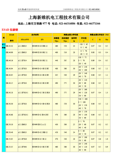
1.5
12.50
G 42 3 M G3Si1
-20 ℃ 70
OK Autrod
EN440 G 38 2 C G3Si1
+20 ℃ 130
A5.18 ER70S-6
470
560
26
0.08 0.9
1.5
气保 12.51
G 42 3 M G3Si1
-20 ℃ 90
焊丝 OK Autrod
EN440 G 42 2 C G4Si1
OK Autrod 12.30
OK Flux 10.45
OK Flux 10.47 OK Flux 10.49 OK Flux 10.50
≈ 1.75
≈ 1.1 ≈ 1.1 ≈ 1.5
OK Autrod 12.10 0.85
OK Autrod 12.22
OK Autrod 12.20 1.3 OK Autrod 12.30
+20 ℃ 130
A5.18 ER70S-6
525
595
26
0.1
1.1
1.7
12.63
G 46 3 M G4Si1
-20 ℃ 90
OK Autrod
EN440 G 42 2 C G4Si1
+20 ℃ 130
A5.18 ER70S-6
525
595
26
0.1
1.0
1.7
12.64
G 46 3 M G4Si1
OK Autrod 12.20
OK Autrod 12.22
A5.18 ER70S-3 A5.18 ER70S-6
EN 1668 W2Si EN 1668 W3Si1
MC33153DG中文资料
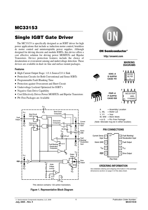
VEE Kelvin VCC 2 GND
Fault 8 Blanking/
Desaturation VEE Input
PIN CONNECTIONS
Current Sense Input
1
Kelvin GND 2
VEE 3
8
Fault Blanking/ Desaturation Input
7 Fault Output
tPLH(in/out)
−
80
300
tPHL (in/out)
−
120
300
Drive Output Rise Time (10% to 90%) CL = 1.0 nF Drive Output Fall Time (90% to 10%) CL = 1.0 nF
tr
−
17
55
tf
−
17
55
Propagation Delay
Features
• High Current Output Stage: 1.0 A Source/2.0 A Sink • Protection Circuits for Both Conventional and Sense IGBTs • Programmable Fault Blanking Time • Protection against Overcurrent and Short Circuit • Undervoltage Lockout Optimized for IGBT’s • Negative Gate Drive Capability • Cost Effectively Drives Power MOSFETs and Bipolar Transistors • Pb−Free Packages are Available
SW-331中文资料

(-55°Cto +85°C) SW-331 SW-333
1.4 1.0 0.9 2.0:1 1.4:1 1.3:1 40 47 52
1.4 1.0 0.9 2.0:1 1.4:1 1.3:1 30 35 40
dB Max dB Max dB Max Max Max Max dB Min dB Min dB Min
元器件交易网
Matched GaAs SPDT Switch DC - 2 GHz
Features
q q q
SW-331, SW-333
V 2.00
SW-331 (CR-2)
Miniature Ceramic Package Fast Switching Speed, 7 ns Typical Ultra Low DC Power Consumption
Functional Schematics
Typical Performance
INSERTION LOSS
VS
FREQUENCY
Pin Configuration
ISOLATION VS FREQUENCY
Truth Table
Electrical Schematic
VSWR
VS
FREQUENCY
Ordering Information
Part Number
SW-331 PIN SW-333 PIN
Package
Ceramic Ceramic
元器件交易网
GaAs SPDT Terminated Switch
SW-338, SW-339
V 2.00
Absolute Maximum Ratings
1
pb331芯片手册

pb331芯片手册摘要:1.引言2.pb331芯片概述3.pb331芯片功能特点4.pb331芯片的硬件结构5.pb331芯片的软件配置6.pb331芯片的应用领域7.总结正文:【引言】本文将为您详细介绍pb331芯片手册的内容,包括芯片概述、功能特点、硬件结构、软件配置以及应用领域等方面的信息。
通过阅读本文,您将对pb331芯片有更深入的了解。
【pb331芯片概述】pb331芯片是一款由我国某公司研发的具有高性能、低功耗的通信处理器。
该芯片专为无线通信领域设计,支持多种通信协议,适用于多种应用场景。
【pb331芯片功能特点】pb331芯片具有以下主要功能特点:1.高性能:采用先进制程工艺,提供较高的运行频率,实现高速数据处理。
2.低功耗:采用低功耗设计,降低运行功耗,延长设备续航时间。
3.多协议支持:支持多种通信协议,如Wi-Fi、蓝牙、GPS等,满足不同应用需求。
4.高度集成:集成丰富的外设接口,简化系统设计,降低整体成本。
【pb331芯片的硬件结构】pb331芯片硬件结构主要包括:CPU、RAM、ROM、通信模块、外设接口等。
这些部分协同工作,实现芯片的各项功能。
【pb331芯片的软件配置】pb331芯片提供了一套完整的软件开发环境,包括驱动程序、协议栈、应用层接口等。
开发者可以根据需求进行软件开发,实现定制化功能。
【pb331芯片的应用领域】pb331芯片广泛应用于各类通信设备,如智能手机、平板电脑、物联网设备等。
此外,该芯片还适用于工业控制、医疗设备、智能家居等多个领域。
【总结】pb331芯片凭借其高性能、低功耗以及多协议支持等特性,在通信处理器市场具有较高的竞争力。
通过本文的介绍,相信您对pb331芯片有了更加全面的了解。
MC33153PG;MC33153DG;MC33153DR2G;MC33153P;MC33153DR2;中文规格书,Datasheet资料
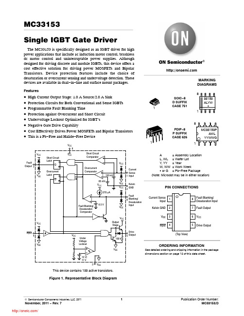
IFO
mA
25
10
Power Dissipation and Thermal Characteristics D Suffix SO−8 Package, Case 751 Maximum Power Dissipation @ TA = 50°C Thermal Resistance, Junction−to−Air P Suffix DIP−8 Package, Case 626 Maximum Power Dissipation @ TA = 50°C Thermal Resistance, Junction−to−Air
Characteristic
Symbol
Min
Typ
Max
Unit
SWITCHING CHARACTERISTICS
Propagation Delay (50% Input to 50% Output CL = 1.0 nF) Logic Input to Drive Output Rise Logic Input to Drive Output Fall
Characteristic
Symbol
Min
Typ
Max
LOGIC INPUT
Input Threshold Voltage High State (Logic 1) Low State (Logic 0)
VIH
−
2.70
3.2
VIL
1.2
2.30
−
Input Current High State (VIH = 3.0 V) Low State (VIL = 1.2 V)
VCC
Current Sense 1 Input
S1D13305中文资料
元器件交易网
The information of the product number change
Starting April 1, 2001, the product number will be changed as listed below. To order from April 1, 2001 please use the new product number. For further information, please contact Epson sales representative.
SDU1374#0C SDU1375#0C SDU1376#0C SDU1376BVR SDU1378#0C
• S1D1380x Series New No. Previous No.
SDU1386#0C
New No.
S5U13806P00C
S5U13503P00C S5U13504P00C S5U13505P00C S5U13506P00C
S1D13305 Series S1D13305D00A S1D13305F00A S1D13305F00B
S1D1370x Series S1D13704F00A S1D13705F00A S1D13706B00A S1D13706F00A S1D13708 Series
• S1D1350x Series Previous No.
S5U13704P00C S5U13705P00C S5U13706P00C S5U13706B32R S5U13708P00C
• S1D13A0x Series Previous No.
SDU13A3#0C SDU13A4#0C
New No.
贴片电容标331 -回复
贴片电容标331 -回复“贴片电容标331”的全称是“贴片多层陶瓷电容标准型号331”,是一种常见的电子元件。
本文将围绕贴片电容标331展开详细介绍,包括其定义、结构、特点、应用领域、选择与购买、使用注意事项等内容。
第一节:定义(150字)贴片电容标331是一种多层陶瓷贴片电容器,属于标准型号,其型号编码为331。
具有固定的电容值和尺寸,适用于广泛的电子电路应用。
第二节:结构(150字)贴片电容标331的结构包括多层陶瓷片和金属电极。
多层陶瓷片由陶瓷材料制成,上面涂覆有导电材料形成电极。
多个陶瓷片相互叠加,形成具有特定电容值的电容器。
两端的金属电极用于引出电容器的正负极。
第三节:特点(200字)贴片电容标331具有以下几个特点:1. 尺寸小巧:由于采用贴片结构,贴片电容标331的尺寸非常小,适合密集的电路板布局。
2. 电容值稳定:多层陶瓷片的结构使得贴片电容标331的电容值稳定,不易受温度和频率的影响。
3. 工作频率宽:贴片电容标331的工作频率范围广,适用于高频和低频电路。
4. 低ESR:贴片电容标331的等效串联电阻(ESR)较低,能够提供良好的电容性能。
5. 高温度耐受性:贴片电容标331能够在较高的温度下正常工作,适用于一些特殊环境。
第四节:应用领域(250字)贴片电容标331广泛应用于各种电子设备和电路中,包括但不限于以下领域:1. 智能手机和平板电脑:在小尺寸的手机和平板电脑中,贴片电容标331被用于电源管理、信号传输和滤波等电路中。
2. 通信设备:在通讯设备中,贴片电容标331可以用于天线匹配电路、滤波电路和耦合电路等。
3. 计算机:在计算机主板和外部设备中,贴片电容标331可应用于电源滤波、去耦等关键电路中。
4. 汽车电子:在汽车电子控制系统中,贴片电容标331可用于发动机控制单元、电动助力转向系统等。
5. 工业控制:贴片电容标331也应用于工业控制设备中,如PLC(可编程逻辑控制器)、变频器等。
ATE33153-说明书-中文

6.5
7.0
V
ISI
-1.4 -10 µA
电流源(Vpin8=0V, Vpin4=0V)
放电电流(Vpin8=15V, Vpin4=5.0V)
器件整体 电源电流 待机(Vpin4=VCC, 输出开路)
工作(CL=1.0nF, f=20kHz)
Ichg Idschg
-200 -270 -300 µA
1.0 2.5
管脚图
丹东奥拓电子有限公司
共4页 第1页
201505
ATE/QB 01.03-2015
版本号 A/201505
ATE33153
最大额定值
参数 电源电压 VCC 至 VEE
开尔文地至 VEE 逻辑输入
电流检测Байду номын сангаас入
消隐/去饱和输入 栅极驱动输入 拉电流
灌电流 二极管箝位电流 故障输出 拉电流 灌电流 功耗和热特性 SOP8 封装 最大功耗@Ta=50°C
mA
7.2 14
ICC
mA 7.9 20
丹东奥拓电子有限公司
共4页 第3页
201505
封装信息
DIP8 单位:mm
ATE/QB 01.03-2015
版本号 A/201505
ATE33153
SOP8 单位:mm
丹东奥拓电子有限公司
共4页 第4页
201505
TJ
TA
Tstg
0.56 180 1.0 100 150
-40~+105
-65~+150
W °C/W
W °C/W
℃
℃
℃
电参数 (VCC=15V,VEE=0V,开尔文地接至 VEE,TA=25℃,除非另外说明)
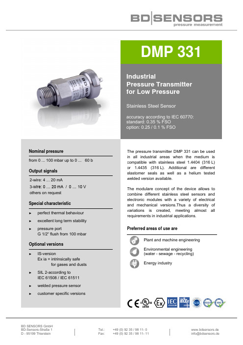
BD SENSORS GmbH DMP 331 工业压力传感器说明书
BD SENSORS GmbH BD-Sensors-Straße 1 Tel.: +49 (0) 92 35 / 98 11- 0www.bdsensors.de D - 95199 ThiersteinFax: +49 (0) 92 35 / 98 11- 11*****************DMP 331IndustrialPressure Transmitter for Low PressureStainless Steel Sensoraccuracy according to IEC 60770: standard: 0.35 % FSO option: 0.25 / 0.1 % FSONominal pressurefrom 0 ... 100 mbar up to 0 ... 60 b Output signals 2-wire: 4 ... 20 mA3-wire: 0 … 20 mA / 0 … 10 V others on request Special characteristic►perfect thermal behaviour ►excellent long term stability ►pressure portG 1/2" flush from 100 mbarOptional versions►IS-versionEx ia = intrinsically safefor gases and dusts ►SIL 2-according toIEC 61508 / IEC 61511►welded pressure sensor ►customer specific versionsThe pressure transmitter DMP 331 can be used in all industrial areas when the medium is compatible with stainless steel 1.4404 (316 L) or 1.4435 (316 L). Additional are different elastomer seals as well as a helium tested welded version available.The modulare concept of the device allows to combine different stainless steel sensors and electronic modules with a variety of electrical and mechanical versions.Thus a diversity of variations is created, meeting almost all requirements in industrial applications. Preferred areas of use arePlant and machine engineeringEnvironmental engineering (water - sewage - recycling) Energy industrypressure and levelwww.bdsensors.deExplosion protection (only for 4 … 20 mA / 2-wire)ApprovalsDX19-DMP 331 IBExU 10 ATEX 1068 X / IECEx IBE 12.0027X zone 0: II 1G Ex ia IIC T4 Gazone 20: II 1D Ex ia IIIC T135 °C DaSafety technical maximum values U i = 28 V, I i = 93 mA, P i = 660 mW, C i ≈ 0 nF, L i ≈ 0 μH,the supply connections have an inner capacity of max. 27 nF to the housingPermissible temperatures for environment in zone 0: -20 ... 60 °C with p atm 0.8 bar up to 1.1 bar in zone 1 or higher: -40/-20 ... 70 °CConnecting cables (by factory)cable capacitance: signal line/shield also signal line/signal line: 160 pF/m cable inductance: signal line/shield also signal line/signal line: 1 μH/mMiscellaneousOption SIL2 version 3 according to IEC 61508 / IEC 61511 Current consumption signal output current: max. 25 mAsignal output voltage: max. 7 mAWeight approx. 200 g Installation position any 4 Operational life 100 million load cycles CE-conformity EMC Directive: 2014/30/EU ATEX Directive 2014/34/EU3 only for4 … 20 mA / 2-wire, not in combination with accuracy 0.1 %4Pressure transmitters are calibrated in a vertical position with the pressure connection down. If this position is changed on installation there can be slight deviations in the zero point for pressure ranges p N ≤ 1 bar.Wiring diagrams2-wire-system (current)3-wire-system (current / voltage)Pin configuration Electrical connectionISO 4400Binder 723 (5-pin)M12x1 / metal(4-pin)Bayonet MIL-C-26482(10-6)2-wire3-wire Supply + Supply –Signal + (for 3-wire)1 2 33 4 1 1 2 3 A B -A D BShieldground pin54pressure portElectrical connectioncompact field housingcable colours (IEC 60757)V S+ V S- S+ GNDSupply + Supply –Signal + (for 3-wire)V S + V S - S+ WH (white) BN (brown) GN (green) ShieldGNDGNYE (green-yellow)psupply +supply –V SIsupply +A/Vsignal +V SpI/Usupply –ISO 4400 Binder series 723, 5-pin M12x1, 4-pin(IP 65) (IP 67) (IP 67)cable outlet with PVC cable cable outlet, cable with(IP 67) 5ventilation tube (IP 68) 6compact field housing(IP 67)universal field housing stainless steel 1.4404 (316 L) with cable gland M20x1.5 (ordering code 880) and other versions on request pressure and levelwww.bdsensors.deDimensions (mm / in)standardSIL- and SIL-IS version* with electrical connection Bayonet MIL-C-26482 (10-6) increases the length of devices by 5 mmMechanical connections (dimensions mm / in)G1/2" DIN 3852 G1/2" EN 837 1/2" NPTG1/4" DIN 3852 G1/4" EN 837 1/4" NPTG1/2" open port DIN 3852G1/2" flush DIN 3852(p N ≤ 40 bar) (p N ≤ 40 bar)DMP331_E_310123Tel.: +49 (0) 92 35 / 98 11- 0www.bdsensors.de Fax: +49 (0) 92 35 / 98 11- 11*****************© 2023 B D |S E N S O R S G m b H – T h e s p e c i f i c a t i o n s g i v e n i n t h i s d o c u m e n t r e p r e s e n t t h e s t a t e o f e n g i n e e r i n g a t t h e t i m e o f p u b l i s h i n g . W e r e s e r v e t h e r i g h t t o m a k e m o d i f i c a t i o n s t o t h e s p e c i f i c a t i o n s a n d m a t e r i a l s .metric threads and other versions on request**-------1101110.1010000.1616000.2525000.4040000.6060001.010011.616012.525014.040016.06001101002161602252502404002606002-1 … 0X 1029999consult123E 1S 9consultstandard for p N ≥ 0.4 bar:0.35 % FSO 3standard for p N < 0.4 bar:0.50 % FSO 5option 1 for p N ≥ 0.4 bar:0.25 % FSO 2option 2:0.10 % FSO19consult100200T A 0cable with ventilation tube (IP68)M 10B G 0B G 4stainless steel 1.4301 (304)999consult 10020030040055H 00N 00N 40999consult1329consult000999consult1 absolute pressure possible from 0.4 bar2 not in combination with SIL3 standard: 2 m PVC cable without ventilation tube (permissible temperature: -5 … 70°C), others on request4code TR0 = PVC cable, cable with ventilation tube available in different types and lengths 5only for p N ≤ 40 bar6welded version only with pressure ports according to EN 837 and NPT31.01.2023customer34T R 0111intrinsic safety 4 … 20 mA / 2-wire2gauge 4 … 20 mA / 2-wire SIL2 4 … 20 mA / 2-wire 0 … 10 V / 3-wire0 … 20 mA / 3-wire absolute customer15, 6without (welded version)© 2023 B D |S E N S O R S G m b H - T h e s p e c i f i c a t i o n s g i v e n i n t h i s d o c u m e n t r e p r e s e n t t h e s t a t e o f e n g i n e e r i n g a t t h e t i m e o f p u b l i s h i n g . W e r e s e r v e t h e r i g h t t o m a k e m o d i f i c a t i o n s t o t h e s p e c i f i c a t i o n s a n d m a t e r i a l s .DMP 331standard G1/4" DIN 3852customercustomerEPDM4 … 20 mA / 2-wirecustomercustomerSIL2 with intrinsic safetymale plug M12x1 (4-pin) / metal ES G1/4" EN 837G1/2" DIN 3852male and female plug ISO 4400male plug Binder series 723 (5-pin)cable outlet with PVC cable (IP67)8customercable outlet,1/4" NPT FKM Bayonet MIL-C-26482 (10-6); 2 wire Bayonet MIL-C-26482 (10-6); 3 wire00F G1/2" EN 837G1/2" DIN 3852501/2" NPT compact field housing G1/2" DIN 3852 open pressure portwith flush sensor。
3313轴承尺寸参数规格

3313轴承尺寸参数规格
3313轴承是一种双列角接触球轴承,通常用于承受径向和轴向负荷的应用。
它的尺寸参数规格如下:
内径(d),65mm.
外径(D),140mm.
宽度(B),58.7mm.
基本额定动载荷,124kN.
基本额定静载荷,104kN.
参考速度,4500转/分钟。
极限转速,5600转/分钟。
这些尺寸参数规格是根据国际标准制定的,对于选择适合的3313轴承来说非常重要。
除了上述的基本参数外,还需要考虑安装
尺寸、润滑要求、适用的工作温度范围等因素。
另外,对于特定的应用,可能还需要考虑轴承的密封性能、材料、精度等方面的参数规格。
在选择3313轴承时,建议根据实际使用条件和要求,综合考虑以上因素,以确保选择到最适合的轴承型号。
奔驰mb331.0刹车油 标准
奔驰mb331.0刹车油标准关于奔驰MB331.0刹车油的标准。
第一步:介绍奔驰MB331.0刹车油的背景和重要性奔驰MB331.0刹车油是一种专门设计用于奔驰汽车的刹车系统的液体。
刹车油在汽车行驶时起着至关重要的作用,可确保刹车系统的正常运行,提高车辆的安全性能。
奔驰MB331.0刹车油有其独特的标准要求,以确保其适用于奔驰汽车的高性能刹车系统。
第二步:解释奔驰MB331.0刹车油的标准要求奔驰MB331.0刹车油的标准要求包括以下几个方面:干沸点、湿沸点、黏度、腐蚀性、阻尼特性和抗氧化性等。
干沸点是指刹车油在没有水份存在的情况下的沸点,湿沸点则是指刹车油在含有水分的情况下的沸点。
这两个参数决定了刹车油在高温下的性能稳定性和抗水分能力。
黏度是指刹车油在不同温度下的流动性能,和高温下的黏度稳定性。
腐蚀性是指刹车油对刹车系统内金属部件的侵蚀能力,阻尼特性则是指刹车油在刹车系统中的抗泡性和抗浪翻性。
抗氧化性是指刹车油对氧化的抵抗能力。
奔驰MB331.0刹车油要求符合以上多项标准,以确保刹车系统的性能和安全性。
第三步:详细解释奔驰MB331.0刹车油标准要求中的各项参数干沸点和湿沸点是刹车油关键的温度性能指标。
干沸点要求刹车油在没有水分存在的情况下,其沸点不低于230,以保证在高温刹车时不会出现沸腾现象。
湿沸点要求刹车油在含有2水份时,其沸点不低于155,以抵抗湿气对刹车系统的侵蚀,防止刹车液沸腾造成刹车系统失效。
黏度是刹车油的流动性能指标。
奔驰MB331.0要求刹车油在-40下的动力黏度不超过1500mm²/s,在-20下的运动黏度不超过150mm²/s,在100下的动力黏度不超过2.5mm²/s。
这些限制确保了刹车油在不同温度下的流动性和黏度稳定性。
腐蚀性是刹车油对刹车系统内金属部件的侵蚀能力。
奔驰MB331.0要求刹车油在特定条件下对金属的腐蚀性不超过15mg/cm²,以避免刹车系统出现腐蚀现象。
3313j-1-103e-调节电位器数据表说明书
*RoHS Directive 2002/95/EC Jan 27 2003 including Annex.†“Fluorinert” is a registered trademark of 3M Co.Specifications are subject to change without notice.Customers should verify actual device performance in their specific applications.Electrical Characteristics Standard Resistance Range........................10 ohms to 2 megohms(see standard resistance table)Resistance Tolerance............±20 % std.End Resistance.......1 % or 3 ohms max.(whichever is greater)Contact Resistance Variation.......................................3 % or 3 ohms AdjustabilityVoltage Divider...........................±0.1 %Rheostat....................................±0.2 %Resolution.....................................Infinite Insulation Resistance................500 vdc.100 megohms min.Dielectric StrengthSea Level..................................500 vac 70,000 Feet...............................350 vac Adjustment Angle...................220°nom.Environmental Characteristics Max. Soldering Exposure..................................260 °C/5 seconds Power Rating (200 volts max.)70 °C ....................................0.125 watt 125 °C .........................................0 watt Operating T emp. Range.....................................-55 °C to +125 °C Temperature Coefficient.....................≤100 ohms ±150 ppm/°C;>100 ohms ±100 ppm/°CSeal Test........................85 °C Fluorinert †-STD 202, Method 106(no vibration) TRS ±3 %;IR 10 megohmsVibration......20 G TRS ±1 %; VRS ±1 %Shock........100 G TRS ±1 %; VRS ±1 %Load Life...............................1000 hours@ 70 °C Rated Power;TRS ±3 %Rotational Life......100 cycles TRS ±3 %Thermal Shock...........................5 cyclesTRS ±2 %; VRS ±1 %Physical CharacteristicsMechanical Angle..................250 °nom.Torque...............................50 g-cm max.Stop Strength...................200 g-cm min.Pushover Strength (“S” only)...........1.6 Kilograms (3.5 lbs) minimum Flammability...........................U.L. 94V-0Weight...........................Approx. 0.01 oz.Marking ........................Resistance codeand date codeWiper................50 % (Actual TR) ±10 %Standard PackagingJ Style.......................1000 pcs./7 ” reel S Style.........................200 pcs./7 ” reel Adjustment Tool..............................H-913313J-1CLOCKWISEDIMENSIONS ARE:MM (INCHES)TOLERANCES: ±0.25 (.010) EXCEPT WHERE NOTED*Ro HSC OMP LI AN T3313X-23313X-1Specifications are subject to change without notice.Customers should verify actual device performance in their specific applications.Meets EIA 48112.40 + 2.00/ -.000(.488 + .079/ -.000)2.67(.105)REELTAPE 2.50 ± .10(.098 ± .004)16.40 + 2.00/ -.000(.646 + .079/ -.000)2.67(.105)REEL3313J/X Packaging Specifications3313S Packaging SpecificationsDIMENSIONS ARE:MM (INCHES)TOLERANCES: ±0.25 (.010) EXCEPT WHERE NOTEDStandard Resistance TablePopular distribution resistance values listed in boldface. Special resistances available.Resistance Part MarkingResistance (Ohms)Code Code 10A110020212005051500100A210120022201500525011,000A31022,000232025,0005350210,000A410320,0002420350,00054503100,000A5104200,00025204500,000555041,000,000A61052,000,00026205REV. 11/06How To Order3313 J - 1 - 502 EModel StyleStandard or Modified Product Indicator -1 = Single Slot -2 =Cross Slot Resistance CodeEmbossed Tape1000 pcs. / 7 ” Reel (J Style)200 pcs. / 7 ” Reel (S Style)RECOMMENDED LAND PATTERN1.57(.062)WIDE DEEP LONG WIDE DEEP LONG Product Dimensions。
331 贴片电阻

331 贴片电阻331贴片电阻,作为一种常见的电子元件,广泛应用于各种电子设备中。
贴片电阻具有体积小、性能稳定、精度高等特点,能够满足各种电路设计的需求。
接下来,我们将进一步了解贴片电阻的种类、性能优势以及在实际应用中的注意事项。
一、贴片电阻的种类贴片电阻根据材质、功率、电阻值等不同参数可分为多种类型。
以下为主要种类:1.碳膜电阻:碳膜电阻具有良好的耐热性能和稳定性,适用于中等功率和精度要求较高的场合。
2.金属膜电阻:金属膜电阻具有较高的精度、稳定性和较低的温度系数,适用于高精度、高稳定性要求的场合。
3.氧化铝电阻:氧化铝电阻具有较高的功率和耐压性能,适用于大功率场合。
4.氮化硅电阻:氮化硅电阻具有极高的功率和耐压性能,适用于极高功率要求的场合。
二、贴片电阻的性能优势1.体积小、重量轻:贴片电阻采用表面贴装技术,具有较小的体积和重量,有利于电子设备的小型化。
2.稳定性高:贴片电阻采用薄膜技术,具有较高的稳定性,能满足各种电路设计要求。
3.精度高:贴片电阻的精度可达到±1%以内,满足高精度电路的需求。
4.耐热性能好:贴片电阻具有良好的耐热性能,可承受较高的温度,适用于各种环境。
5.寿命长:贴片电阻具有较长的使用寿命,能在恶劣环境下保持良好的性能。
三、贴片电阻的应用注意事项1.选型:根据电路需求,选择合适的贴片电阻类型和参数。
2.焊接:贴片电阻焊接时,应选用合适的焊接设备和焊接材料,避免对电阻性能造成损害。
3.安装:在安装过程中,注意保护电阻表面,避免损伤。
4.环境条件:贴片电阻在使用过程中,应注意环境温度的变化,避免高温或低温环境对电阻性能产生影响。
5.电源电压:确保电源电压稳定,避免电压波动对电阻造成损害。
总之,贴片电阻作为一种重要的电子元件,具有体积小、稳定性高、精度高等优点,广泛应用于各种电子设备。
在实际应用中,我们应充分了解贴片电阻的种类、性能优势以及注意事项,确保电阻发挥最佳性能。
3314j电位器参数

3314j电位器参数
3314j是一种电位器型号,通常用于调节电路中的电阻值。
它是一种单轴电位器,具有3个引脚,其中两个是固定端,一个是可变端。
3314j电位器的参数包括阻值范围、公差、功率额定值和温度系数等。
首先,阻值范围是指电位器可调节的电阻数值范围,通常以欧姆(Ω)为单位。
3314j电位器的阻值范围可能在几十欧姆至几兆欧姆之间,具体取决于型号和规格。
其次,公差是指电位器实际阻值与标称阻值之间的允许偏差范围。
一般来说,公差越小,电位器的精度越高。
3314j电位器的公差通常以百分比或者绝对值表示,例如5%的公差表示实际阻值可能偏离标称阻值的5%。
第三,功率额定值是指电位器能够承受的最大功率。
3314j电位器的功率额定值可能在几瓦特到几十瓦特之间,具体取决于型号和尺寸。
最后,温度系数是指电位器阻值随温度变化的稳定性。
温度系
数通常以ppm/℃(百万分之一/摄氏度)来表示,例如50ppm/℃表示在温度每上升1摄氏度时,阻值会上升50百万分之一。
较低的温度系数意味着电位器对温度变化的影响较小。
总的来说,3314j电位器的参数包括阻值范围、公差、功率额定值和温度系数,这些参数决定了它在电路中的具体应用和性能表现。
希望这些信息能够帮助到你。
CSESJ350 3

• Operating Manual • Warning Information• Parts ListCSESJ3503½ TonService JackMeets or exceeds ASME PALD-2005standards for performance & safety.Copyright © Professional Tool Products, 2009All rights reserveddeScripTionCSESJ350 service jack is a self-contained device designed for lifting, but not sustaining, a partial vehicular load. It consists of a frame with wheels and swivel casters supporting a mechanism that actuates a pivoting lift arm equipped with a saddle. It is designed for use by professional auto mechanics.***owner/uSer reSponSibiliTyThe owner and/or user must have an understanding of the manufacturer’s operating instructions and warnings before using this jack. Personnel involved in the use and operation of equipment shall be careful, competent, trained, and qualified in the safe operation of the equipment and its proper use when servicing motor vehicles and their components. Warning information should be emphasized and understood. If the operator is not fluent in English, the manufacturer’s instructions and warnings shall be read to and discussed with the operator in the operator’s native language by the purchaser/owner, making sure that the operator comprehends its contents.Owner and/or user must study and maintain for future reference the manufacturer’s instructions and pertinent warning information. Owner and/or user is responsible for keeping all warning labels and instruction manuals legible and intact. Replacement labels and literature are available from the manufacturer.inSpecTionVisual inspection should be made before each use of the jack, checking for leaking hydraulic fluid and damaged, loose or missing parts. Each jack must be inspected by a manufacturer’s repair facility immediately, if subjected to an abnormal load or shock. Any jack which appears to be damaged in any way, is found to be badly worn, or operates abnormally MUST BE REMOVED FROM SERVICE until necessary repairs are made by a manufacturer’s authorized repair facility. It is recommended that an annual inspection of the jack be made by a manufacturer’s authorized repair facility and that any defective parts, decals or warning labels be replaced with manufacturer’s specified parts. A list of authorized repair facilities is available from the manufacturer.OPERATIONIMPORTANT: Before attempting to raise a vehicle, check vehicle service manual for recommended lifting surfaces.1. To raise load: Close release valve tightly (by turning handle clockwise). DO NOT OVERTIGHTEN. Position jack under load so that saddle will contact load firmly and load is centered so it cannot slip. Operate jack handle until saddle approaches the load. Once again check to see that saddle is correctly positioned. Raise load to desired height. Place jack stands of appropriate capacity under the vehicle. DO NOT CRAWL UNDER VEHICLE WHILE LIFTING VEHICLE OR PLACING OR REMOVING JACK STANDS! Place jack stands at vehicle manufacturer's recommended lift areas that provide stable support for the raised vehicle.2. To lower load: Open release valve VERY SLOWLY (by turning handle counterclockwise). When release valve is opened, saddle and load will be lowered. Lower the vehicle slowly so as not to shock load the jack stands. Once repairs are completed, raise vehicle enough to remove jack stands. Lower vehicle very slowly.CAUTION: Keep hands or feet away from the hinge mechanism of the jack.hydraulic JacK mainTenanceIMPORTANT: Service jacks are designed for lifting purposes only; always support raised load with jack stands.regular mainTenance• Monthly or as necessary (depending on usage)1. Using a grease gun, add grease to grease fitting in the lift arm pivot shaft. (Use a multi-purpose NLGI type grease only.)2. Lubricate all linkages and pivot points. (Use white lithium spray grease only.)3. Remove handle; lubricate handle receptacle and handle end. (Use white lithium spray grease only.)4. Lubricate both rear casters, bearings and both front wheels. (Use white lithium spray grease only.)5. Tighten all accessible hardware.CSESJ350 Power Unit* Included in Seal Kit - RS35NSKOnly items identified by part number are available for purchase.RS35B20NPARTS BREAKDOWN - CSESJ350Item PartNo.No.DescriptionQty.1 RS35T01 Retaining Ring2 2 RS35T02 Washer 23 RS35B03 Front Wheel2 4 RS35B10 Rear Caster Ass'y.2 5 RS35T08 Hex Nut & Lock Washer2 6 RS35B11 Yoke Retaining Bolt & Washer 2 7 RS35T17 Handle Lever "B" 1 8 RS35T15 Handle Lever "A" 1 9 RS35009C Handle Bumper 1 10 RS35T13 Set Screw - Handle 1 11 RS35011C Handle Yoke 1 12 RS35B20N Power Unit Ass'y. 1 13 RS35T18 Universal Joint Ass'y.1 14 RS35B24 Block Linkage (incl. Split Pin, Ret. Rings) 1 15 RS35T12 Grease Fitting 1 16 RS35T04 Retaining Ring 2 17 RS35017 Saddle1 18 RS35018 Saddle Screw1 19 RS35019C Rubber Saddle Pad 1 20 RS35T19 Spring2Index PartNo.No.DescriptionQty.1 * Steel Ball 5 62 Large Pump Housing 13 * O-Ring 15 x 2.65 24 * Back-Up Washer 20 x 15.6 x 1.25 2 5 Big Pump Piston 16 Pump Spring 17 RSDC22N Dust Cover1 8 Washer1 9 RSRR27N Retaining Ring 201 10 RS35T18 Universal Joint Assembly1 11 * Steel Ball 6 1 12 * Brass Washer 2 13 Small Pump Housing 1 14 * O-Ring 10 x 2.65 2 15 * Back-Up Washer 15 x 10.6 x 1.25 2 16 Small Pump Piston 1 17 Pump Spring 1 18 RSDC15 Dust Cover1 19 Washer1 20 RSRR16 Retaining Ring 151 21 RS0FS37 Screw (incl. #22 o-ring)3 22 * O-Ring 7.1 x 1.8 3 23 Relief Valve Bolt 2 24 * Relief Valve Spring 2 25 * Plug 2 26 * Steel ball 4 1 27 Hydraulic Block 1 28 * Cylinder Seal 1 29 Cylinder 1 30 * O-Ring 31 x 4.6 1 31 * Gasket 1 32 Ram Bearing 1 33 Retaining Ring 30 1 34 Ram 1 35 Cylinder Nut 1 36 * O-Ring 29.6 x 3.5 1 37 * Gasket 1 38 Reservoir Tube 1 39 * Gasket 1proper STorageIt is recommended that this jack be stored in a dry location with all wheels touching the ground on a relatively level surface. TroubleShooTingImportant: Service jacks are self-contained devices used for lifting, but not sustaining, a partial vehicular load. In accordance with ASME-PALD standard, section 10-4.1.2 Load Sustaining Test: “A load not less than the rated capacity…shall not lower more than 1/8” (3.18mm) in the first minute, nor a total of .1875” (4.76mm) in 10 minutes.” Leak down within this range is considered normal operation and is NOT a warrantable defect.WARRANTY COVERAGECornwell Quality Tools Company (“Cornwell”) warrants against defects the hydraulic pump on this product for a period of TWO (2) YEARS from the date of original retail purchase. Cornwell Quality Tools Company (“Cornwell”) warrants against defects the balance of components on this product for a period of 90 days from the date of original retail purchase. Subject to the conditions and limitations set forth below, Cornwell will, at its option, either repair or replace any part of the product(s) that proves defective by reason of improper workmanship or materials.This warranty does not cover any damage to this product that results from accident, abuse, misuse, natural or personal disaster, or any unauthorized disassembly, repair, or modification. Repairs, disassembly and modification are only authorized to be made by Cornwell or a warranty service center approved by Cornwell. WARRANTY SERVICETo obtain warranty service, contact your Cornwell dealer.EXCLUSIONS AND LIMITATIONSTHIS WARRANTY AND THE REMEDIES SET FORTH ABOVE ARE EXCLUSIVE AND IN LIEU OF ALL OTHER WARRANTIES, REMEDIES AND CONDITIONS, WHETHER ORAL OR WRITTEN, EXPRESS OR IMPLIED. CORNWELL SPECIFICALLY DISCLAIMS ANY AND ALL IMPLIED WARRANTIES, INCLUDING, TO THE EXTENT PERMITTED BY APPLICABLE LAW, ANY WARRANTIES OF MERCHANTABILITY AND FITNESS FOR A PARTICULAR PURPOSE. IF CORNWELL CANNOT LAWFULLY DISCLAIM IMPLIED WARRANTIES UNDER THIS LIMITED WARRANTY, ALL SUCH IMPLIED WARRANTIES ARE LIMITED IN DURATION TO THE DURATION OF THIS WARRANTY. IN NO EVENT SHALL CORNWELL BE LIABLE TO THE PURCHASER OR TO THE USER OF A CORNWELL PRODUCT FOR ANY SPECIAL, INCIDENTAL OR CONSEQUENTIAL DAMAGES BASED UPON BREACH OF WARRANTY, BREACH OF CONTRACT, NEGLIGENCE, TORT, OR ANY OTHER LEGAL THEORY. SUCH DAMAGES INCLUDE, WITHOUT LIMITATION, EXPENSES, LOST REVENUES, LOST SAVINGS, LOST PROFITS, OR ANY OTHER INCIDENTAL OR CONSEQUENTIAL DAMAGES ARISING FROM THE PURCHASE, USE OR INABILITY TO USE THE CORNWELL PRODUCT.Some states do not allow the exclusion or limitation of incidental or consequential damages or exclusions or limitation on the duration of implied warranties or conditions, so the above limitations or exclusions may not apply to you. This warranty gives you specific legal rights, and you may also have other rights that vary by state. Repair kits and replacement parts are available for many Cornwell products, regardless of whether or not the product is still covered by a warranty plan.Cornwell Quality Tools Company667 Seville Road • Wadsworth, OH 44281-1094。
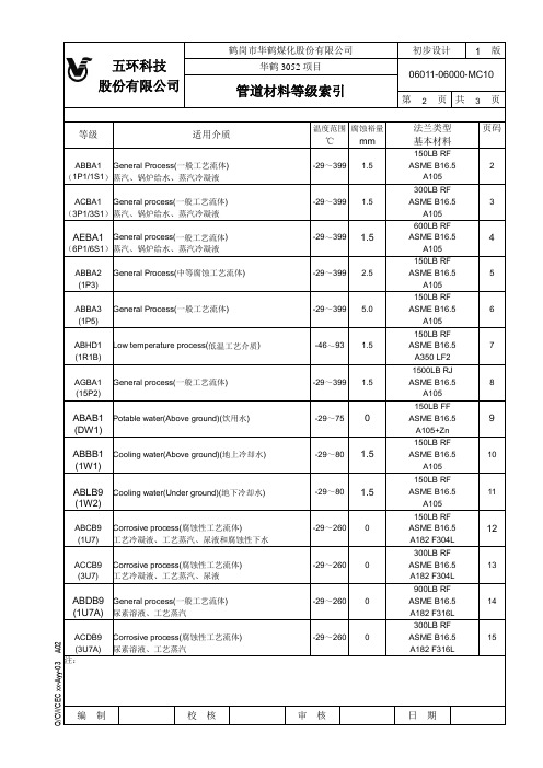
3-3-3.3-4b 管道材料等级索引(尿素装置)
(1R1B)
A350 LF2
1500LBRJ
AGBA1
General process(一般工艺流体)
-29~399
1.5
ASME B16.5
8
(15P2)
A105
150LBFF
ABAB1
Potable water(Above ground)(饮用水)
-29~75
0
ASME B16.5
9
(DW1)
A105+Zn
(3U7)
工艺冷凝液、工艺蒸汽、尿液
A182 F304L
900LBRF
ABDB9
General process(一般工艺流体)
-29~260
0
ASME B16.5
14
(1U7A)
尿素溶液、工艺蒸汽
A182 F316L
300LBRF
ACDB9
Corrosive process(腐蚀性工艺流体)
-29~260
AGEA9
甲铵液、二氧化碳、尿液、工艺蒸汽
-29~399
0
ASTM316LMOD
17
(15U3)
注:
1.5
ASME B16.5
3
(3P1/3S1)
蒸汽、锅炉给水、蒸汽冷凝液
A105
600LBRF
AEBA1
General process(一般工艺流体)
-29~399
1.5
ASME B16.5
4
(6P1/6S1)
蒸汽、锅炉给水、蒸汽冷凝液
A105
150LBRF
ABBA2
General Process(中等腐蚀工艺流体)
0
电阻331

电阻331
电阻是一种电子元件,其用于限制电路中电流流动的数量。
331系列电阻也称作1/3W 电阻,是一种常规的电阻,广泛应用于电子电路中,并被广泛使用于电子产品中。
331电阻是特种电阻,与其他电阻相比,它的特点是小而轻,有一种薄膜状的结构。
因此,331电阻可以被放置在有限的空间内,以满足它受限的空间和使用要求。
另外,它的驱动电流很低,且有很高的直流电阻值和额定功率,能够有效抑制热效应,使用寿命更长。
331电阻的额定电压是1/4W,最高工作温度为125摄氏度。
一般它有五种不同的阻值:2R2-2R7,3R3-3R9,4R3-4R7,6R8-6R8,8R2-8R2。
331电阻常用于电子系统,如手机和其他电子设备中。
331电阻在降低波动电源和滤波电路中扮演着重要的角色,它可以抑制不利于整个系统的大噪声,具有极好的低频衰减特性。
它还能抑制外界电磁波的干扰,保持正常的通信对设备的协作和工作的正常进行。
此外,331电阻小巧、轻量级易于安装,即使电路和环境都有很大变化,其制造精度也不会受到影响。
331电阻的温度稳定性也很高,在特定温度范围内,它可以保持电阻值的精度和可靠性,保证电路稳定工作和长时间使用期限。
总之,331电阻具有小型、低驱动电流、高耐压,以及较高的直流电阻和额定功率,方便安装,可靠性强,功能多样的特性,可以满足不同的使用要求,为电子领域的发展提供了重要的依据。
贴片电容标331
贴片电容标331
(最新版)
目录
1.贴片电容的概述
2.贴片电容的命名规则
3.贴片电容的种类和特点
4.贴片电容的应用领域
5.贴片电容的市场前景
正文
1.贴片电容的概述
贴片电容,又称片式电容器,是一种表面安装型元器件。
它是一种多层陶瓷电容器,以其体积小、容量大、可靠性高、寿命长等特点,广泛应用于各类电子产品中。
2.贴片电容的命名规则
贴片电容的命名规则通常由三个数字和一个字母组成。
例如,331,其中第一个数字代表电容的体积,第二个数字代表电容的电介质材料,第三个数字代表电容的封装形式,最后一个字母代表电容的类型。
3.贴片电容的种类和特点
贴片电容主要有以下几种类型:
- 陶瓷贴片电容:具有体积小、容量大、稳定性好等特点,适用于高频电路。
- 钽贴片电容:具有体积小、容量大、漏电流小等特点,适用于低电压、高稳定性的电路。
- 铝贴片电容:具有体积大、容量小、稳定性较差等特点,适用于低
频电路。
4.贴片电容的应用领域
贴片电容广泛应用于各类电子产品,如手机、电脑、家电、通信设备等。
其主要作用是滤波、耦合、旁路等,对电路的稳定性和性能有着重要的影响。
5.贴片电容的市场前景
随着科技的发展和电子产品的普及,贴片电容的市场需求不断增长。
预计在未来几年,全球贴片电容市场将保持稳定的增长态势。
- 1、下载文档前请自行甄别文档内容的完整性,平台不提供额外的编辑、内容补充、找答案等附加服务。
- 2、"仅部分预览"的文档,不可在线预览部分如存在完整性等问题,可反馈申请退款(可完整预览的文档不适用该条件!)。
- 3、如文档侵犯您的权益,请联系客服反馈,我们会尽快为您处理(人工客服工作时间:9:00-18:30)。
■ Packaging Specifications
Standard Reel Dimensions in mm (not to scale)
Taping Reel
φ382.0±2.0 25.0 3.0 3.0 END Carrier tape 1.75±0.1 P=20±0.1 Drawing direction 4±0.1 2±0.1 φ1.5+0.1 0.2
12.5
1.0
3.5
0.3 10.0
φ1.5±0.1 1.0 7.75 12.5
0.3 1.0
6
12.5
φ1.5±0.1
+0 0 .1
1.0 7.75
0. 3
6-2.3 1.0
1.0
2.5
2.5
1. 7
0 -R 24
.4
+0 0 .1
φ1
.2
N.C. C N.O. N.C.
C
φ1
6-1.6
2.5
.7
2.5
10.0 PWB mounting hole for reference (Tolerance: ±0.05) View from terminal side
C N.O. Circuit diagram
8.7
C N.O. Circuit diagram
PWB mounting hole for reference Tolerance : ±0.05 (t=1.6 mm)
N.O. 8.6 1.5±0.3 Lock travel 2.3±0.5 Full travel 3.9±0.2 C N.C.
N.O. C N.C. 9.85
N.O. C 1.5±0.3 Lock travel
C
3.3±0.05 2.5
4.9 2.75
4.9 2.75
1.0
(6.5)
(6.5)
6.0
Note: PP=Self-lock NL=Non-lock
Design and specifications are each subject to change without notice. Ask factory for the current technical specifications before purchase and/or use. Should a safety concern arise regarding this product, please be sure to contact us immediately.
■ Application Notes:
● Operating force should be applied at the center of the lever.
Design and specifications are each subject to change without notice. Ask factory for the current technical specifications before purchase and/or use. Should a safety concern arise regarding this product, please be sure to contact us immediately.
Embossed Carrier Taping
Cover tape TOP 21.5±0.5
24±0.3
Non-packed portion (160 mm min.)
Packed portion
Non-packed portion (100 mm min.) Leading portion 400 mm min.
consumer electronic equipment and different types of mode switches
■ Explanation of Part Numbers
1 2 3 4 5 6 7 8
E
S
Product Code
B
3
Type
3
Design No.
■ Specifications
元器件交易网
Push Switches/ESB33 ESB33 Vertical Push Switches
Type:
ESB33 (H=6.0 mm)
■ Features
● Low profile (H=6.0 mm) ● 3 N and 5 N operating force availables ● A wide range of acceptable currents from microcomputer
Apr. 2008
元器件交易网
Push Switches/ESB33
■ Dimensions in mm (not to scale)
No. 1 ESB33133 2-poles 2-throws No. 2 ESB33536 2-poles 2-throws
N.O. 8.6 C N.C. 9.85 2.5±0.1
controls to relay control signals
■ Recommended Applications
switches etc.)
● Operation switches for automobiles (heater con trol ● Secondary power switches for lower voltage in
■ Standard Products
Operating Mode PP 3.0 N±1.0 N NL PP NL PP NL Surface Mount Embossed Taping (Reel ) 3.0 N±1.0 N ESB33536 Wave Soldering Polyethylene Bag (Bulk) 5.0 N±1.5 N ESB33154 ESB33535 Light Yellow ESB33134 ESB33153 Black Terminals Packaging Operating Force Part Numbers ESB33133 Light Yellow Lever Color
Rating Travel Mounting Height Poles and Throws Operating Mode Switching Mode Minimum Quantity/Packing Unit Quantity/Carton 50 µA 3 Vdc to 0.2 A 14 Vdc (Resistive load) Lock travel=1.5 mm Full travel=2.3 mm 6.0 mm 2-poles 2-throws Self-lock, Non-lock Non-shorting 100 pcs. Polyethylene Bag (Bulk) / 300 pcs. Embossed Taping (Reel Pack) 2000 pcs. Polyethylene Bag (Bulk) / 1800 pcs. Embossed Taping (Reel Pack)
Feb. 2008
2.3±0.5 Full travel N.C. N.O. N.C.
N.C.
C 3 0.
C 3 0.
C 3 0.
