OX4580A-LZ中文资料
0458020011;中文规格书,Datasheet资料

This document was generated on 08/14/2012PLEASE CHECK FOR LATEST PART INFORMATIONPart Number:45802-0011Status:ActiveOverview:HD Mezz™Description:1.20mm by2.00mm Pitch HD Mezz™ Receptacle, 143 Circuits, 8.00mm Unmated Height, 11 Rows, Tin-LeadDocuments:3D ModelTest Summary TS-45802-005 (PDF)Drawing (PDF)Test Summary TS-45802-008 (PDF)Product Specification PS-45802-001 (PDF)Test Summary TS-45802-901 (PDF)Application Specification AS-45802-001 (PDF)RoHS Certificate of Compliance (PDF)Test Summary TS-45802-001 (PDF)Agency CertificationCSA LR19980ULE29179GeneralProduct Family PCB Receptacles Series45802Application Board-to-Board, SignalComments 1.20mm Pitch Pin-to-Pin and 2.00mm Pitch Row-to-Row OverviewHD Mezz™Product Name Mezzanine UPC822348849413PhysicalCircuits (Loaded)143Circuits (maximum)143Color - ResinBlack Durability (mating cycles max)100Flammability94V-0Glow-Wire Compliant No Guide to Mating Part No Keying to Mating Part None Lock to Mating Part YesMaterial - MetalHigh Performance Alloy (HPA)Material - Plating MatingGold Material - Plating Termination Tin-LeadMaterial - Resin High Temperature Thermoplastic Net Weight7.020/g Number of Rows 11Orientation Vertical PCB Locator Yes PCB RetentionYes PCB Thickness - Recommended 1.60mm Packaging TypeTray Pitch - Mating Interface2.00mm Pitch - Termination Interface 2.00mm Plating min - Mating0.762µm Plating min - Termination 2.540µm Polarized to Mating Part Yes Polarized to PCB YesRobotic Placement Vacuum Pick-Up Tape StackableNo Surface Mount Compatible (SMC)YesSeriesimage - Reference onlyEU RoHSChina RoHSNot RoHS Compliant REACH SVHC Not ReviewedLow-Halogen Status Not ReviewedNeed more information on product environmental compliance?Email productcompliance@For a multiple part number RoHS Certificate of Compliance, click herePlease visit the Contact Us section for any non-product compliance questions.Search Parts in this Series 45802SeriesMates With45830 HD Mezz™ PlugTemperature Range - Operating-55°C to +105°CTermination Interface: Style Surface MountUnmated Height8.50mmElectricalCurrent - Maximum per Contact2AGrounding to PCB NoVoltage - Maximum250V ACSolder Process DataDuration at Max. Process Temperature (seconds)20Lead-free Process Capability Reflow Capable (SMT only)Max. Cycles at Max. Process Temperature2Process Temperature max. C260Replacement RoHS Compliant Part Number0458020311Material InfoReference - Drawing NumbersApplication Specification AS-45802-001Product Specification PS-45802-001Sales Drawing SD-45802-0001, SD-45802-0002Test Summary TS-45802-001, TS-45802-005, TS-45802-008,TS-45802-901This document was generated on 08/14/2012PLEASE CHECK FOR LATEST PART INFORMATION分销商库存信息: MOLEX 0458020011。
21554-AA资料
21554PCI-to-PCI Non-Transparent Bridge Evaluation BoardUser’s GuideJanuary2001Order Number: 273475-00121554PCI-to-PCI Non-Transparent Bridge Evaluation Board21554PCI-to-PCI Non-Transparent Bridge Evaluation Board Contents1Introduction.............................................................................................................................1-51.1Overview.........................................................................................................................1-51.2Features............................................................................................................................1-51.3Major Components..........................................................................................................1-61.3.1Local or Secondary Bus Connectors.................................................................1-61.3.2Test Point Pods..................................................................................................1-71.3.3Jumpers.............................................................................................................1-71.3.4Switch Packs.....................................................................................................1-71.3.5Devices..............................................................................................................1-71.4Switch Settings................................................................................................................1-81.5Stake-Pin Jumpers...........................................................................................................1-91.6Clock Configuration......................................................................................................1-101.7Clamping Voltage..........................................................................................................1-111.8Local Bus Slot Numbering and IDSEL Mapping..........................................................1-121.9Interrupt Routing...........................................................................................................1-131.10Typical Configurations..................................................................................................1-14 2Operation and Installation.................................................................................................2-12.1Specifications..................................................................................................................2-12.2Hardware Requirements..................................................................................................2-12.3Software Requirements..................................................................................................2-22.3.1SROM Programming........................................................................................2-22.3.2Flash ROM Programming.................................................................................2-32.4DE1B55401Installation Procedure.................................................................................2-4 3Optional Configurations.....................................................................................................4-13.1PICMG Configuration.....................................................................................................4-13.2Central Function and Arbiter Control..............................................................................4-23.3Asynchronous Clocking..................................................................................................4-2A Signal and Default Information (3)A.1Test Pod Pin Outs (3)A.2Factory Default Switch and Jumper Configuration (5)21554PCI-to-PCI Non-Transparent Bridge Evaluation BoardIntroduction Introduction1 This document describes the21554PCI-to-PCI nontransparent Bridge Evaluation Board(referredto as the DE1B55401).1.1OverviewThe DE1B55401is a PCI expansion board that is used to evaluate the operation of the21554whenused as a gateway to an intelligent subsystem.The subsystem can use a variety of PCI devices andlocal processors.The DE1B55401can be used to perform the following functions:•Develop initialization code to configure the21554and associated logic and devices on the local PCI bus as a intelligent controller•Evaluate the operation of the21554with a variety of PCI devices configured in an intelligent subsystem.•Build and evaluate a system using synchronous and asynchronous clocking•Testing of features such as:—I2O*transactions—Power management features—Vital Product Data(VPD)support1.2FeaturesThe DE1B55401has the following features:•Complies fully with the protocol and electrical standards of Revision2.2of the PCI Local Bus Specification.•Includes a21554“nontransparent”PCI-to-PCI Bridge that provides bridging between two processor domains.•Includes a host PCI interface that plugs into any5V PCI option card slot.•Provides four local bus5V PCI bus option card slots.One slot may be used as a localprocessor or system slot.•Support,products,and documentation.IntroductionIntroductionIntroductionIntroductionTable1-2.Jumper ConnectionsJumpers FunctionJ22When installed,it enable l_stat pull-up resistor for Hot-Swap Functionality testing and enables operation of LED1.J23When installed,s_ad<24>is IDSEL when J101is a PCI Option slot. When not installed,pin A26is GNT2from the local processor.J24Enables pr_cs control of the flash ROM’s CE.See Table2-2on page2-3. J25Enables pr_cs control of the socket ROM’s CE.IntroductionIntroductionTable 1-4.Voltage Clamp aa.Only one jumper resistor (R95or R97)may be installed at a time.Installing both or no jumper resistors is not allowed.Clamping Voltage InstalledRemoved3.3V s_vio R41R635V s_vioR63R41IntroductionIntroductionIntroductionIntroductionOperation and Installation Operation and Installation2 This chapter provides information about the DE1B55401specifications,hardware,and softwarerequirements.It also describes how to install the DE1B55401.2.1SpecificationsThe physical and power specifications for the DE1B55401are:Dimensions:•Height:20.2cm(8.0in)•Width:17.8cm(7.0in)Power Requirements:•DC amps@5V:2A(maximum)•On Board3.3volt regulator for s_vio and Vdd5A(Maximum)2.2Hardware RequirementsThe following equipment is required to use the DE1B55401:•A computer system equipped with a PCI option slots.•A PCI expansion slot on the motherboard that is equipped for the5-V PCI environment•PCI option cards used to create the local subsystem•An optional local processor to control the subsystemThe local processor can be used out of the any PCI slots.The top PCI slot is configurable as aPICMG CPU slot.Operation and InstallationOperation and InstallationTable2-4.DBFLASH.EXE Command SummaryCommand Description CommentsDbflash/e Erase entire flash ROM contents Will erase all blocksDbflash/bx image.bin Program block x with image.bin If image larger than1block,program will continue into the next block until entire image is loaded.Operation and InstallationOptionalConfigurationsOptional Configurations33.1PICMG ConfigurationThis chapter describes how to configure the DE1B55401for a Single Board Computer (SBC)with a PCI interface as defined be the PICMG PCI-ISA interface specification.The DE1B55401can support an intelligent subsystem on the local bus.The intelligent subsystem is architectureindependent.The 21554can interface to the PCI interface of any intelligent subsystem.The J101connector has the capability of accepting an intelligent controller.Table 3-1details the jumper options necessary for this mode of operation.To operate a controller on the local bus the clocks have to be routed accordingly.Table 3-2identifies the series of zero ohm resistors that must be configured to implement the system slot as the clock source.Table 3-1.PICMG Stake Pin JumperJumperFunctionJ23When installed,use s_ad<24>as IDSEL when J101is a PCI Option slot.When removed a ,pin A26becomes GNT2from local processor.Correct routing of s_idsel for Slot J101.a.Factory default.Table 3-2.PICMG Options JumpersFunctionInstalled Removed System slot drives s_clk_i on the 21554R67R66,R65System slot provides local clockR90,R91,R92,R93R97,R98,R99,R100OptionalConfigurationsTable 3-4.REQ#and GNT#SelectionSwitch PackSwitch a a.All switches must be either up or down for correct operation.Request/Grant Switch DownSystem slot (J102)as arbiter Switch Up21554as arbiter J21SW2req#1REQ1from PICMG slot REQ1from 21554SW3gnt#1GNT1from PICMG slot GNT1from 21554SW4req#2REQ2from PICMG slot REQ2from 21554SW5gnt#2GNT2from PICMG slot GNT2from 21554J20SW1req#3REQ2from PICMG slot REQ2from 21554SW2gnt#3GNT2from PICMG slotGNT2from 21554Table 3-5.Synchronous or Asynchronous Clock ControlSwitch PackSwitchSwitch DownSwitch UpDescriptionJ20SW3Synchronous host and local clock domains Asynchronous host and local clock domains Synchronous/Asynchronous Operation pr_ad<4>SW4Disable 21554s_clk_oEnable 21554s_clk_os_clk_o pr_ad<5>Signal and Default InformationAA.1Test Pod Pin OutsTest points are accessible through board mounted Header type connectors,which are referred to as pods.The following tables give the schematic name of the signal that can be found at each pod pin.All even numbered pod pins are grounded.All odd numbered pod pins connect to a unique signal that is documented on the 21554Bridge Reference Design Schematic.Table A-1associates the pod pin numbers to the secondary bus control signals and address and data lines.See Figure 1-1for the location of this connector.Table A-1.Secondary Bus Test PodsSecondary Bus Control SignalsPod Pin a Numbera.All even numbered pod pins are wired to earth ground.J9J17J13J81S_FRAME S_REQ3S_CBE3S_CBE43S_IRDY S_GNTC3S_CBE2S_CBE55S_TRDY S_REQ2S_CBE1S_CBE67S_DEVSEL S_GNTC2S_CBE0S_CBE79S_STOP S_REQ1P_GNT S_ACK6411S_PERR S_GNTC1P_REQ S_REQ6413S_SERR S_REQ0(no connection)S_PAR6415S_PARRS_GNTC0(no connection)(no connection)Secondary Address and Data PodsPod Pin a NumberJ10S_AD<0:7>J12S_AD<8:15>J11S_AD<16:23>J14S_AD<24:31>1S_AD7S_AD15S_AD23S_AD313S_AD6S_AD14S_AD22S_AD305S_A5S_AD13S_AD21S_AD297S_AD4S_AD12S_AD20S_AD289S_AD3S_AD11S_AD19S_AD2711S_AD2S_AD10S_AD18S_AD2613S_AD1S_AD9S_AD17S_AD2515S_AD0S_AD8S_AD16S_AD24Signal and Default InformationS_CLK0_D5PR_WR S_CLK0_C7PR_RD CLKB9PR_CS P_PCLK11PR_ALE(no connection)13PR_CLK(no connection)15P_MGGEN(no connection)Signal and Default Information。
OX2094A-LZ中文资料

OCXO SERIES 9400"FEATURES APPLICATIONS Excellentfrequencystability -TELECOM High Frequency up to 100MHz - BASE STATIONLowProfile -INSTRUMENTATION "ELECTRICAL PERFORMANCEPARAMETER OCXO SERIES 9400AT CUT CRYSTAL SC CUT CRYSTAL Supply voltage, nom. 12V, 5V,3.3V ±5% StandardPower dissipation steady state 2 Watt Max.Heat up power 5 Watt Max.Heat up time. 5 min MaxFrequency range 10 To 100MHz StandardFrequency Adjustment:Electrical (0 to 5V) Electrical (0 to 10V) ±10PPM Min±15PPM Min±0.7PPM Min±1PPM Min±0.05 PPM±0.15 PPM±0.010 PPM±0.020 PPMFreq. stability vs. temperatureLX: 0°C to 60°CFZ: -30°C to 70°C(Standard, contact factory for different temp ranges and stabilities) Freq. stability vs. supplychanges±0.01 PPM Max for ±5% Change ±0.005 PPM Max for ±5% Change Freq. stability vs. load changes ±0.005 PPM Max for ±5% Change ±0.002 PPM Max for ±5% ChangeLong term stability (Aging) ± 0.5 PPM Max for 1 Years±0.005 PPM/Day Max. ±0.1 PPM Max for 1 Years ±0.002 PPM/Day Max.Output HCMOS/TTL/Sine 0 to +10dBmHarmonics, Sub Harmonics -30dBc(Sine Output)Spurious -75dBc(SineOutput) Duty cycle 40/60% to 60/40%(HCMOS)Rise / fall time 10nS Max. (HCMOS,10%~90%Vout, 90%~10%Vout)Short term Stability (10MHz) 1 E-10 /Sec 5 E-11 /SecPhase Noise typical under static conditions(Sine Output 10MHZ) Offset Phase Noise10Hz -95 dBc/Hz100Hz -125 dBc/Hz1000Hz -135 dBc/Hz10000Hz -150 dBc/HzOffset Phase Noise10Hz -115 dBc/Hz100Hz -135 dBc/Hz1000Hz -145 dBc/Hz10000Hz -150 dBc/HzNote: All Typical parameters for a 10MHz output and 5V Supply, for different frequencies consult factory"HOW TO ORDER (PART NUMBER)Prefix OutputType Cut Type Series Revision Temperature Range Stability Frequency SupplyVoltageOX 1:TTL2:HCMOS3:ACMOS4:LVCMOS6:SINE 0:AT (No Vcontrol )1: SC (No Vcontrol )4: AT (Elect Vcontrol)5: SC (Elect Vcontrol)94: 9400 AFirst letter LowestTemperature,Second letter HighestTemperature:From A=-55°C toZ=+70°C, Then:1=+75°C, 2=+80°C,3=+85°C… in 5°Csteps Example:LZ: +0°C to +70°CLX: +0°C to +60°CFZ: -30°C to +70°CD3: -40°C to +85°CValue x 10E-2in PPMExample28=0.28PPM10=0.1PPMIn MHZ 3.3; 3.3V5: 5.0V12; 12V Prefix: OCXOMECHANICAL SPECIFICATION。
AA51880中文资料

AA51880中⽂资料Agamem Technology Inc. AA51880PRELIMINARY SERVO MOTOR CONTROLLERINTRODUCTIONThe AA51880 is a BJT integrated circuit for use in servo motor control applications.The built -in voltage regulato r provides the AA51880 with ex tremely stable output voltage.FEATURESBuilt-in voltage regulator.Larger driving capability. Small outline package.APPLICATIONSServo motor control.Radio controlled car, boat, airplane. IA products (such as air-condition).BLOCK DIAGRAMFUNCTION DESCRIPTIONTiming control block detects the motor position and adjust dead band. Output driver circuit control the servo motor current direction. The voltage regulator supports the application reference voltage.V INOT L T DB ST EXP1OUT1 OUT2 EXP2V REGAgamem Technology Inc.AA51880PRELIMINARY SERVO MOTOR CONTROLLERPIN ASSIGNMENTPIN DESCRIPTION Pin No Symbol Name & Function1 R T Timing Resistor2 EXP1 External PNP Transi stor 1 output3 OUT1 Output Driver 14 NC No Connection5 OUT2 Output Driver 26 EXP2 External PNP Transistor 2 output7 C ST Stretcher capacitor8 NC No Connection9 V REG Regulated Voltage output 10 V CC Power pin 11 R DB Error pulse output 12 GND Ground pin 13 GND Ground pin14 V IN Input signal15 P OT Servo position voltage 16C TTiming Capacitor12345678161514131211109(Top View)R T EXP1OUT1NC OUT2EXP2C ST NCC T P OT V IN GND GND R DB Vcc V REGAA51880Agamem Technology Inc.AA51880PRELIMINARY SERVO MOTOR CONTROLLERRATINGS (Ta=25¢J, unless otherwise noted)ELECTRICAL CHARACTERISTICS (Ta=25¢J and Vcc=4.8V, unless otherwise noted)VOLTAGE REGULATOR OUTPUT VOLTAGE CHARACTERISTIC (Ta=25¢J)4321V CC V R e gAgamem Technology Inc.AA51880 PRELIMINARY SERVO MOTOR CONTROLLER APPLICATION CIRCUITAgamem Technology Inc.AA51880PRELIMINARYSERVO MOTOR CONTROLLERn SSOP PACKAGE DIMENSIONPLAN。
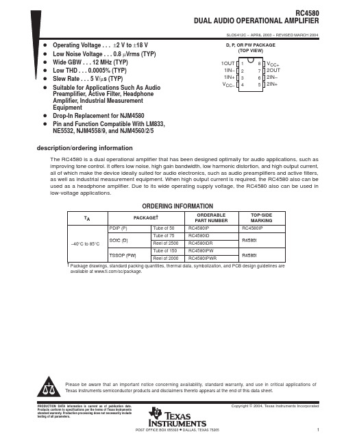
MC4580资料
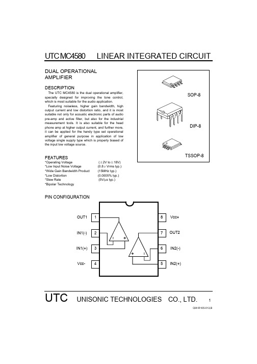
UTC MC4580LINEAR INTEGRATED CIRCUITUTC UNISONIC TECHNOLOGIES CO., LTD.1QW-R105-013,BDUAL OPERATIONAL AMPLIFIERDESCRIPTIONThe UTC MC4580 is the dual operational amplifier,specially designed for improving the tone control,which is most suitable for the audio application.Featuring noiseless, higher gain bandwidth, high output current and low distortion ratio, and it is most suitable not only for acoustic electronic parts of audio pre-amp and active filter, but also for the industrial measurement tools. It is also suitable for the head phone amp at higher output current, and further more, it can be applied for the handy type set operational amplifier of general purpose in application of low voltage single supply type which is properly biased of the input low voltage source.FEATURES*Operating Voltage (±2V to ±18V) *Low Input Noise Voltage (0.8μVrms typ.) *Wide Gain Bandwidth Product (15MHz typ.) *Low Distortion (0.0005% typ.) *Slew Rate (5V/µs typ.) *Bipolar TechnologyPIN CONFIGURATION12348765OUT2IN2(-)IN1(+)Vcc-Vcc+OUT1IN1(-)IN2(+)UTC MC4580LINEAR INTEGRATED CIRCUITUTC UNISONIC TECHNOLOGIES CO., LTD.2QW-R105-013,BTEST CIRCUITVcc+ABSOLUTE MAXIMUM RATINGS (Ta=25°C)PARAMETER SYMBOL RATINGSUNIT Supply Voltage V +/V - ±18 VInput VoltageV IC ±15 V Differential Input Voltage V ID ±30 V Output Current Io ±50mA Power DissipationP D 300 (SOP-8)800 (DIP-8) 250(TSSOP-8)mWOperating Temperature Range Topr -40 to+85 °C Storage Temperature RangeTstg -40 to +125°CUTC MC4580LINEAR INTEGRATED CIRCUITUTC UNISONIC TECHNOLOGIES CO., LTD.3QW-R105-013,BELECTRICAL CHARACTERISTICS (V + /V -=±15V, Ta=25°C )PARAMETER SYMBOLTEST CONDITION MINTYP MAXUNITInput Offset VoltageV IO R S ≤10k Ω - 0.5 3 mVInput Offset Current I IO - 5 200 nA Input Bias Current I B - 100 500 nA Large Signal Voltage Gain A V Vo=±10V, R L ≥2k Ω90 110 - dBOutput Voltage SwingV o M R L >=2k Ω±12±13.5- V Input Common Mode Voltage Range V ICM ±12±13.5- V Common Mode Rejection Ratio CMR R S ≤10k Ω 80 110 - dB Supply Voltage Rejection Ratio SVR Rs ≤10k Ω 80 110 - dB Operating Current Icc - 6 9 mA Slew Rate SR R L ≥2k Ω - 5 - V/µs Gain bandwidth Product GB f=10KHz - 15 - MHz Total Harmonic Distortion THD Av=20dB,Vo=5V, R L =2k Ω, f=1KHz - 0.0005 - % Input Noise Voltage V NI RIAA Rs=2.2 k Ω,30kHzLPF- 0.8 - µVrmsTYPICAL CHARACTERISTICSMaximum Output Voltage Swing vs. Load Resistance Maximum Output Voltage Swing vs. FrequencyOutput Voltage Swing vs. Output CurrentEquivalent Input Noise Voltage vs. FrequencyUTC MC4580LINEAR INTEGRATED CIRCUITUTC UNISONIC TECHNOLOGIES CO., LTD.4QW-R105-013,BOperating Current vs. TemperatureOutput Voltage Swing vs. TemperatureInput Offset Voltage vs. TemperatureInput Bias Current vs. TemperatureMaximum Output Voltage Swing vs. Operating Voltage Operating Current vs. Operating VoltageUTC MC4580 LINEAR INTEGRATED CIRCUITUTC UNISONIC TECHNOLOGIES CO., LTD.5QW-R105-013,BTotal Harmonic Distortion vs. Output VoltageVoltage Gain, Phase vs. Frequency。
MEMORY存储芯片ADM485ARZ-REEL中文规格书
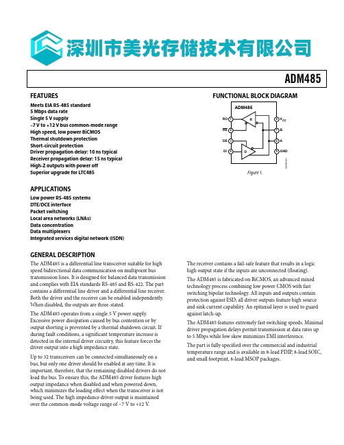
ADM485FUNCTIONAL BLOCK DIAGRAMCC 00078-001FEATURESMeets EIA RS-485 standard 5 Mbps data rateSingle 5 V supply–7 V to +12 V bus common-mode range High speed, low power BiCMOS Thermal shutdown protection Short-circuit protectionDriver propagation delay: 10 ns typical Receiver propagation delay: 15 ns typical High-Z outputs with power off Superior upgrade for LTC485APPLICATIONSLow power RS-485 systems DTE/DCE interface Packet switchingLocal area networks (LNAs) Data concentration Data multiplexersIntegrated services digital network (ISDN)GENERAL DESCRIPTIONThe ADM485 is a differential line transceiver suitable for high speed bidirectional data communication on multipoint bus transmission lines. It is designed for balanced data transmission and complies with EIA standards RS-485 and RS-422. The part contains a differential line driver and a differential line receiver. Both the driver and the receiver can be enabled independently. When disabled, the outputs are three-stated.The ADM485 operates from a single 5 V power supply. Excessive power dissipation caused by bus contention or by output shorting is prevented by a thermal shutdown circuit. If during fault conditions, a significant temperature increase is detected in the internal driver circuitry, this feature forces the driver output into a high impedance state.Up to 32 transceivers can be connected simultaneously on a bus, but only one driver should be enabled at any time. It is important, therefore, that the remaining disabled drivers do not load the bus. To ensure this, the ADM485 driver features high output impedance when disabled and when powered down, which minimizes the loading effect when the transceiver is not being used. The high impedance driver output is maintained over the common-mode voltage range of −7 V to +12 V .Figure 1.The receiver contains a fail-safe feature that results in a logic high output state if the inputs are unconnected (floating). The ADM485 is fabricated on BiCMOS, an advanced mixed technology process combining low power CMOS with fast switching bipolar technology. All inputs and outputs contain protection against ESD; all driver outputs feature high source and sink current capability. An epitaxial layer is used to guard against latch-up.The ADM485 features extremely fast switching speeds. Minimal driver propagation delays permit transmission at data rates up to 5 Mbps while low skew minimizes EMI interference. The part is fully specified over the commercial and industrial temperature range and is available in 8-lead PDIP , 8-lead SOIC, and small footprint, 8-lead MSOP packages.ADM485Rev. F | Page 2 of 16ADM485SPECIFICATIONSV CC = 5 V ± 5%, all specifications T MIN to T MAX, unless otherwise noted.Rev. F | Page 3 of 16ADM485TIMING SPECIFICATIONSV CC = 5 V ± 5%, all specifications T MIN to T MAX, unless otherwise noted.1 Guaranteed by characterization.Rev. F | Page 4 of 16ADM485Rev. F | Page 5 of 16ABSOLUTE MAXIMUM RATINGST A = 25°C, unless otherwise noted.Stresses above those listed under Absolute Maximum Ratings may cause permanent damage to the device. This is a stress rating only; functional operation of the device at these or any other conditions above those indicated in the operationalsection of this specification is not implied. Exposure to absolute maximum rating conditions for extended periods may affect device reliability.Table 4. TransmittingInputsOutputsDE DIB A 1 1 0 1 1 0 1 0 0X 1Z 2Z 21 X = don’t care.2Z = high impedance.1 X = don’t care.2Z = high impedance.ESD CAUTION。
EZJZZV800AA中文资料
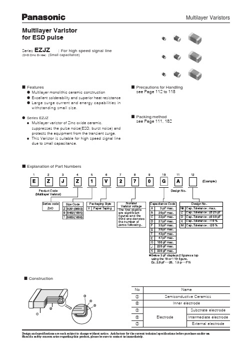
(Unit: mm)
A Symbol
Size Code
B W F E P1 P2 P0 fD t1 t2
0201 0402
0.37 0.67
0.5 0.8
±0.03 ±0.03 8.0 3.50 1.75 2.00 2.00 4.0 1.5 max. max.
0.62
±0.05
1.12
±0.05
±0.2 ±0.05 ±0.10 ±0.05 ±0.05 ±0.05 +0.1 0
n Precautions for Handling see Page 112 to 118
n Packing method see Page 111, 182
n Explanation of Part Numbers
1
2
3
4
5
6
7
8
9
10
11
12
EZ J Z 1 V 2 7 0GA
(Example)
n Typical Characteristics
l Voltage vs. Current
1000
100
10
EZJZ V171 A
EZJZ V800 A
EZJZ V500 A
EZJZ V330 A EZJZ V270 EZJZ V120
A A
1
0.000001 0.00001 0.0001 0.001
0201 EZJZZV270RA EZJZ0V120JA
0402 EZJZ0V270RA EZJZ0V270EA EZJZ1V120KA
0603 EZJZ1V270GA EZJZ1V330GA
4580的中文资料
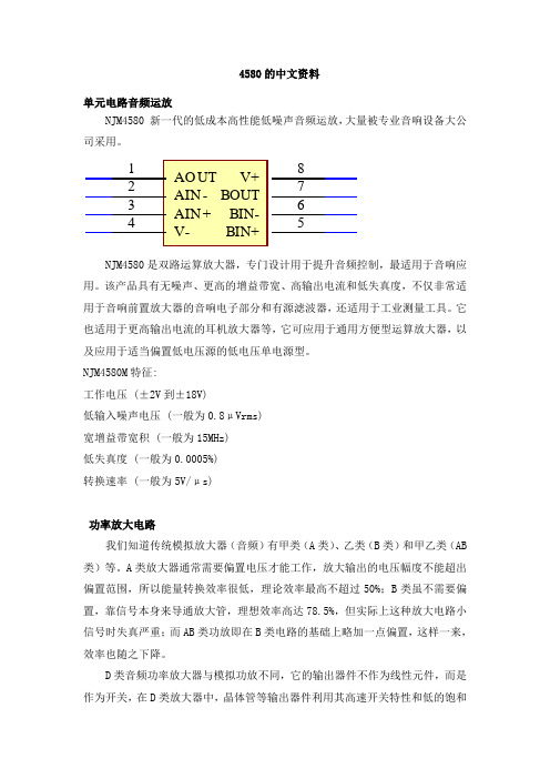
4580的中文资料单元电路音频运放NJM4580 新一代的低成本高性能低噪声音频运放,大量被专业音响设备大公司采用。
AO UT 1AIN -2AIN +3V-4BIN+5BIN-6BOUT7V+8IC9NJM4580 NJM4580是双路运算放大器,专门设计用于提升音频控制,最适用于音响应用。
该产品具有无噪声、更高的增益带宽、高输出电流和低失真度,不仅非常适用于音响前置放大器的音响电子部分和有源滤波器,还适用于工业测量工具。
它也适用于更高输出电流的耳机放大器等,它可应用于通用方便型运算放大器,以及应用于适当偏置低电压源的低电压单电源型。
NJM4580M 特征:工作电压 (±2V 到±18V)低输入噪声电压 (一般为0.8μVrms)宽增益带宽积 (一般为15MHz)低失真度 (一般为0.0005%)转换速率 (一般为5V/μs)功率放大电路我们知道传统模拟放大器(音频)有甲类(A 类)、乙类(B 类)和甲乙类(AB 类)等。
A 类放大器通常需要偏置电压才能工作,放大输出的电压幅度不能超出偏置范围,所以能量转换效率很低,理论效率最高不超过50%;B 类虽不需要偏置,靠信号本身来导通放大管,理想效率高达78.5%,但实际上这种放大电路小信号时失真严重;而AB 类功放即在B 类电路的基础上略加一点偏置,这样一来,效率也随之下降。
D 类音频功率放大器与模拟功放不同,它的输出器件不作为线性元件,而是作为开关,在D 类放大器中,晶体管等输出器件利用其高速开关特性和低的饱和压降的特点,其功耗小、效率很高,通常可达90%以上,又此电路不需要严格的对称,也不需要复杂的直流偏置和负反馈,使稳定性大大提高。
用同样的功耗的管子可得到比甲乙类放大器高4倍功率的输出,所以D类是高效、节能、数字化音频功率放大器。
D类音频功率放大器工作原理D类音频功率放大器通常由PWM调制器、PCM-PWM转换器、脉冲推动器/功率放大器、低通滤波器这几部分组成。
4580N;中文规格书,Datasheet资料

/
分销商库存信息:
EBM-PAPST 4580N
/
4580 N
AC axial compact fan
Product drawing
Web data sheet XI · Page 3 of 4 ebm-papst St. Georgen GmbH & Co. KG · Hermann-Papst-Straße 1 · D-78112 St. Georgen · Phone +49 7724 81-0 · Fax +49 7724 81-1309 · info2@ ·
/
4580 N
AC axial compact fan
Charts: Air flow
(in H ² O) 0,05 0,10 0,15
∆ pf ä
Pa
40
30
20
10
0
15
30
45
60
CFM50
75
100
Web data sheet XI · Page 4 of 4 ebm-papst St. Georgen GmbH & Co. KG · Hermann-Papst-Straße 1 · D-78112 St. Georgen · Phone +49 7724 81-0 · Fax +49 7724 81-1309 · info2@ ·
Nominal data
Type Phase Nominal voltage Frequency Speed Power input Min. ambient temperature Max. ambient temperature Air flow Sound power level Sound pressure level VAC Hz min-1 W °C °C m3/h B dB(A) 4580 N 1~ 230 50 2350 18.0 -10 55 123 5.2 41
8205a中文资料
8205a中文资料锂电池保护板根据使用的不同IC和电压具有不同的电路和参数。
常用的保护IC是8261,DW01 +,CS213,GEM5018等。
其中,精工的8261系列具有更好的精度,当然价格也更昂贵。
后者全部在台湾制造。
国内二级市场主要使用DW01 +和CS213。
以下是带有MOS管8205A(8pin)的DW01 +的说明:锂电池保护板的正常工作流程为:当电池电压在2.5V至4.3V之间时,DW01的第一引脚和第三引脚均输出高电平(等于电源电压),第二引脚电压为0V。
此时,DW01的引脚1和3的电压将分别施加到8205A的引脚5和4。
由于8205A中的两个电子开关的G 极连接到DW01的电压,因此它们处于导通状态。
两个电子开关均处于打开状态。
此时,电池单体的负极直接连接至保护板的P-端子,并且保护板具有电压输出。
2.保护板过放电保护控制原理:当电池通过外部负载放电时,电池电压将缓慢降低,与此同时,DW01将通过R1电阻实时监控电池电压。
当电池电压降至约2.3V时,DW01将认为电池电压处于过放电电压状态,引脚1的输出电压立即断开,从而引脚1的电压变为0V,并且开关由于引脚5上没有电压,因此8205A中的电子管关闭。
此时,电池单元的B-和保护板的P-处于断开状态。
即,电池单元的放电电路被切断,并且电池单元将停止放电。
保护板处于过放电状态,并且已经维护。
保护板的P 和P-具有间接充电电压后,DW01通过B-检测到充电电压后,将立即停止过放电状态,并再次在引脚1上输出高电压以开启过放电控制8205A中的电子管。
也就是说,电池单元的B-和保护板的P-被重新连接,并且电池由充电器直接充电。
3.保护板过充保护控制原理:当电池由充电器正常充电时,随着充电时间的增加,电池的电压将越来越高。
当电池电压升至4.4V时,DW01将认为电池电压处于过充电电压状态。
然后立即断开引脚3的输出电压,以使引脚3的电压变为0V,并且由于引脚4上没有电压,因此8205A中的开关管被闭合。
Z540中文资料(Intel)中文数据手册「EasyDatasheet - 矽搜」
Inte l proce ssor num be rs are not a m easure of pe rform ance . Proce ssor num be rs diffe re ntiate feature s within each proce ssor
Intel Virtualization Technology (Intel VT) requires a com puter system with an enabled Intel processor, BIO S, virtual m achine m onitor (VMM) and, for som e uses, certain platform software enabled for it. Functionality, perform ance or other benefits will vary depending on hardware and software configurations and m ay require a BIO S update. Software applications m ay not be com patible with all operating system s. Please check with your application vendor.
LZ编程器说明书
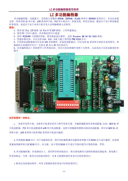
LZ多功能编程器多功能编程器,功能强大。
支持绝大多数的EPROM、EEPROM、FLASH和串行EEPROM系列芯片,并且还直接支持一些常用的51单片机,AVR系列单片机,PIC单片机芯片;价格及低,性价比很高;既适合于电子和电脑爱好者使用,也适合于电子电单片机开发人员和脑维修人员使用。
特性:1、使用32 Pin ZIF插座 18 Pin针型DIP插座,工作性能稳定。
2、使用PC 打印口通讯,具有极高的写片速度。
3、采用 WINDOWS下的图形界面,使用鼠标进行操作,支持 Windows ME/98/95/2000系统。
4、性能价格比高,可以支持810、815、845主板上使用的FWH BIOS芯片。
5、不用添加适配器就可以支持200多种器件,在添加适配器后,可以支持51系列单片机的全系列型号,和最新的大容量程序芯片!支持3.3V及2.9V电压的芯片。
6、具有编程指示!控制程序工作界面友好,对芯片的各种操作变得十分简单,无论是电子还是电脑爱好者都可应用范围和一些特点:1.用来开发单片机:为使单片机爱好者学习和开发更方便, 本编程器配套有各种适配器,比如:MCS-51单片机适配器、PIC单片机适配器和AVR单片机适配器。
这样只需根据需要购买相应的适配器,即可对MCS-51系列单片机,AVR系列单片机和PIC系列单片机进行编程。
2.用来刷新BIOS芯片对于电脑爱好者,则可用此编程器对电脑的各种板卡的BIOS芯片进行编程。
比如修复被病毒破坏的主板BIOS芯片,对主板、显卡等的BIOS芯片进行升级以提升计算机性能,等等。
3.多功能编程器,在电路设计上,采用科学的布线设计,将全部电路用大面积的地线包围起来,使电路工作更加稳定、可靠。
配有汉化的驱动程序,对E文烦感的爱好者也可以轻松使用它。
4.配有汉化的驱动程序,对E文烦感的爱好者也可以轻松使用它。
多功能BIOS 编程器支持的芯片 芯片类型 芯片型号单片机芯片 需51适配器转换座 89系列:Atmel :AT89C51、52、55、 AT89LV51、52、55AT89S8252 (8K+2K)、 AT89S53、 AT89LS8252、AT89LS53AT89C1051、AT89C2051、AT89C4051 (20pin)AT89C51RC (32KB)、 AT89C55WD (6.2V)SST89C54/58、 SI89C52Intel :i87C51、 i87C51FA 、 i87C51FBi8xC51、i8xC52、i8xC54、i8xC5890系列:AT90S1200、AT90S231390S2333、 90S4433、 90S4414、 90S8515、 90S4434、 90S8535,AT90S231316位EPROM(DIP40)(1-4Mbit)27C1024 (27C210)、 27C2048 (27C2002)、 27C4096 (27C4002) 需使用Eprom DIP40转换座 16位EPROM(DIP42)(4-32Mbit)M27C400(DIP40)、 27C800、 27C160、 27C322 需使用Eprom DIP42转换座 电擦除EPROM W27E512、 W27E010、 W27C010、 W27C020、 W27C040SST27SF256、 SST27SF512、 SST27SF010、 SST27SF020MX26C4000Vcc = 3.3-3.6V SST37VF512、 SST37VF010、 SST37VF020、 SST37VF040EEPROM 28C65、28C64、 28C128、 28C256、28C512、 28C010、 28C020、 28C040M28C16A/17A (DIP28)28C16、XLS2816 (DIP24)AT28C64B 、AT28C256、AT28C512、AT28C010、AT28C020、AT28C040FLASH Memory28F64、 28F128、 28F256、 28F512、28F010、 28F020MX26C1000、 MX26C2000、 MX28F1000、 MX28F2000Am28F256A 、 Am28F512A 、 Am28F010A 、 Am28F020Aintel :i28F001BX 、 28F004、 28F008、 28F016SST28SF040A 、LE28F400129F64、 29F128、 29F256、 29F512、29F010、 29F020、 29F040、 29F08029F001、29F002、 29F004、 29F008、 29F016、 29F032AT29C256、 AT29C512、AT29C010A 、 AT29C020、 AT29C040、AT29C040AW29EE512、W29EE011、 W29EE012、 W29C020(128)、W29C040PH29EE010(W29EE011)ASD AE29F1008 (AT29C010)、 AE29F2008 (AT29C020)AT49F512、 AT49F010、 AT49F020、 AT49F040SST39SF010、 SST3S9F020 、SST39SF040AT49F001、AT49F002 、 AT49F008AAm29F512、 Am29F010、 Am29F020、 Am29F040、HY29F08029F002、 29F002T 、 Pm29F002T 使用TSOP48转换座支持: Am29F400、Am29F800、29F160、29F320 (read 、write byte mode) HY29F200、 HY29F400、 HY29F800 、 AT49F2048A 、 AT49F4096A 、 AT49F8192A使用TSOP48转换座支持(Vpp12V ): i28F200、i28F400、i28F800、i28F160 (TSOP48)28F001(DIP32 or PLCC32)使用TSOP48LV转换座支持:29LV200、 29LV400、29LV800、29LV160、29LV320 (read、write byte mode)使用Firmware Hub/LPC (PLCC32)转换座支持:Firmware Hub芯片:82802AB、 82802AC、 AT49LW040、 AT49LW080SST49LF002A、 SST49LF003A、 SST49LF004A、 SST49LF008A LPC flash芯片:SST49LF020、 SST49LF040串行(I2C) EEPROM 24C02、24C04、24C08、24C16、 85C72、 85C82、 85C9224C32、24C64、24C128、24C256、24C512 (全部C、LC系列) PCF8572 或8572,PCF8582或8582,PCF8592或8592Microwire EEPROM 8位模式:93C06、 93C46、 93LC46、 93C56、 93C57、93C66、 93C76、 93C86、93C13、93C1416位模式:AT59C11、 AT59C22、 AT59C13CAT35C102、 CAT35C104、 CAT35C10893C06A 、93C46X、93C56、93C66、93C76、93C86 (NS)PIC单片机16C5X、17XXX、18XXX系列使用PIC单片机转换座支持:12C508、12C508A、12C509、12C509A 12CE518、12CE519 12C671、12C672、12CE673、12CE674 16C505 16C61、16C620、16C621、16C622A 16F627、16F628、16C71、16C715 16C84、16F83、16F84、16F84A 16C64A、16C65A、16C65B、16C67 16C74A、16C74B、16C77 16F871、16F874、16F877 16C62A、16C62B、16C63、16C63A、16C66 16C72、16C72A、16C73A、16C73B、16C76 16F870、16F872、16F873、16F876SPI EEPROM Atmel:AT25010、020、 040 (A8-A0)AT25080、 160、 320、 640、 128、 256 (A15-A0)ST:W95010....256、 Microchip 25x010 - 25x64025010、25020、2504025C080、25C160、25C320、25C640、25C128、25C256、25C512 AT25HP256、AT25HP512AT25HP1024CAT64LCxxx (16位数据I/O)CAT64LC010、 CAT64LC020、 CAT64LC040测试SRAM、非易失SRAM功能DS1220、DS1225Y、 DS1230Y/AB、 DS1245Y/AB、 DS1249Y/AB 6116、 6264、 62256、 62512、 628128EPROM 27C16、27C32、27C64、27C128、27C256、27C512、27C010、27C020、27C040、27C1001 M27C1001、M27C2001、M27C400127C080,M27C801,M87C2572716(Vpp25V)、2732、2764、27128、27256、27512、27010需使用Atmel AT89 PLCC44转换座P8048AH、 P8049AH、P8050AH、 P8042AH (Vea = 12V)P8041、 P8042OTP (read/verify/Progam)P8748、P8749H、P8742H(Vea = 18V)EPROM (read/verify/Progam)D8748、D8749、D8742、D8741、 D8742(Vea = 18V)从上面的列表中,我们可以发现,如果我们使用FWH(PLCC32)转换座,我们用此编程器可以支持最新几乎所有主板上的BIOS芯片,多功能BIOS编程器都可以支持,真正是一款性价比较高的编程器。
PS2805A-1-F4-A中文资料
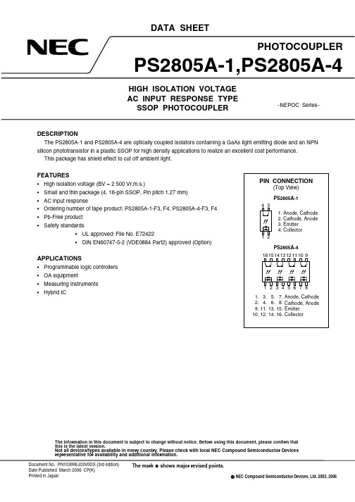
DESCRIPTIONThe PS2805A-1 and PS2805A-4 are optically coupled isolators containing a GaAs light emitting diode and an NPN silicon phototransistor in a plastic SSOP for high density applications to realize an excellent cost performance. This package has shield effect to cut off ambient light.FEATURES• High isolation voltage (BV = 2 500 Vr.m.s.)• Small and thin package (4, 16-pin SSOP, Pin pitch 1.27 mm) • AC input response• Ordering number of tape product: PS2805A-1-F3, F4, PS2805A-4-F3, F4 • Pb-Free product • Safety standards • UL approved: File No. E72422• DIN EN60747-5-2 (VDE0884 Part2) approved (Option)APPLICATIONS• Programmable logic controllers • OA equipment • Measuring instruments • H ybrid ICThe mark shows major revised points.DATA SHEETThe information in this document is subject to change without notice. Before using this document, please confirm thatthis is the latest version.Not all devices/types available in every country. Please check with local NEC Compound Semiconductor Devices representative for availability and additional information.Document No. PN10399EJ03V0DS (3rd edition)Date Published March 2006 CP(K) Printed in JapanNEC Compound Semiconductor Devices, Ltd. 2003, 2006PACKAGE DIMENSIONS (UNIT: mm)MARKING EXAMPLE2Data Sheet PN10399EJ03V0DSORDERING INFORMATIONPart Number Order Number Solder PlatingSpecificationPacking StyleSafety StandardsApprovalApplicationPart Number*1PS2805A-1 PS2805A-1-A Pb-Free 50 pcs (Tape 50 pcs cut) Standard products PS2805A-1PS2805A-1-F3 PS2805A-1-F3-A EmbossedTape 3 500 pcs/reel (UL approved)PS2805A-1-F4 PS2805A-1-F4-APS2805A-4 PS2805A-4-A Magazine Case 45 pcs PS2805A-4PS2805A-4-F3 PS2805A-4-F3-A Embossed Tape 2 500 pcs/reelPS2805A-4-F4 PS2805A-4-F4-APS2805A-1-V PS2805A-1-V-A 50 pcs (Tape 50 pcs cut) DIN EN60747-5-2 PS2805A-1PS2805A-1-V-F3 PS2805A-1-V-F3-A EmbossedTape 3 500 pcs/reel (VDE0884 Part2)PS2805A-1-V-F4 PS2805A-1-V-F4-A Approved(Option)PS2805A-4-V PS2805A-4-V-A Magazine Case 45 pcs PS2805A-4PS2805A-4-V-F3 PS2805A-4-V-F3-A Embossed Tape 2 500 pcs/reelPS2805A-4-V-F4 PS2805A-4-V-F4-A*1 For the application of the Safety Standard, following part number should be used.Data Sheet PN10399EJ03V0DS 3ABSOLUTE MAXIMUM RATINGS (T A = 25°C, unless otherwise specified)UnitRatingsParameter SymbolPS2805A-1 PS2805A-4Diode Forward Current (DC) I F±30 mA/chPower Dissipation Derating ∆P D/°C 0.6 0.8 mW/°CPowerDissipation P D 60 80 mW/chPeak Forward Current*1I FP±0.5 A/chTransistor Collector to Emitter Voltage V CEO 70 VEmitter to Collector Voltage V ECO 5 VCurrent I C 30 mA/chCollectorPower Dissipation Derating ∆P C/°C 1.2 mW/°CPowerDissipation P C 120 mW/chVr.m.s.500Isolation Voltage*2 BV2Operating Ambient Temperature T A−55 to +100 °CStorage Temperature T stg−55 to +150 °C*1PW = 100 µs, Duty Cycle = 1%*2AC voltage for 1 minute at T A = 25°C, RH = 60% between input and outputPins 1-2 shorted together, 3-4 shorted together (PS2805A-1).Pins 1-8 shorted together, 9-16 shorted together (PS2805A-4).4Data Sheet PN10399EJ03V0DSELECTRICAL CHARACTERISTICS (T A = 25°C, unless otherwise specified)Parameter Symbol Conditions MIN.TYP.MAX.Unit Diode ForwardVoltage V F I F = ±5 mA 1.2 1.4 VTerminalCapacitanceC t V = 0 V, f = 1.0 MHz 20pFTransistor Collector to Emitter DarkCurrentI CEO V CE = 70 V, I F = 0 mA 100 nACoupled Current Transfer Ratio(I C/I F)CTR I F = ±5 mA, V CE = 5 V 50 400 %Collector SaturationVoltageV CE(sat)I F = ±10 mA, I C = 2 mA 0.13 0.3 VIsolationResistanceR I-O V I-O = 1.0 kV DC 1011ΩIsolationCapacitanceC I-O V = 0 V, f = 1.0 MHz 0.4 pFRiseTime*1T r V CC = 5 V, I C = 2 mA, R L = 100 Ω 5 µsFallTime*1t f 7*1 Test circuit for switching timeV CCData Sheet PN10399EJ03V0DS 5TYPICAL CHARACTERISTICS (T A = 25°C, unless otherwise specified)1Ambient Temperature T A (˚C)D i o d e P o w e r D i s s i p a t i o n P D (m W )DIODE POWER DISSIPATION vs.AMBIENT TEMPERATUREAmbient Temperature T A (˚C)T r a n s i s t o r P o w e r D i s s i p a t i o n P C (m W )TRANSISTOR POWER DISSIPATION vs.AMBIENT TEMPERATUREForward Voltage V F (V)F o r w a r d C u r r e n t I F (m A )FORWARD CURRENT vs.FORWARD VOLTAGECollector to Emitter Voltage V CE (V)C o l l e c t o r C u r r e n t I C (m A )COLLECTOR CURRENT vs.COLLECTOR TO EMITTER VOLTAGEAmbient Temperature T A (˚C)COLLECTOR TO EMITTER DARKCURRENT vs. AMBIENT TEMPERATUREC o l l e c t o r t o E m i t t e rD a r k C u r r en t I C E O (n A )Collector Saturation Voltage V CE (sat) (V)C o l l ec t o r C u r r e n t I C (m A )COLLECTOR CURRENT vs.COLLECTOR SATURATION VOLTAGERemark The graphs indicate nominal characteristics.Data Sheet PN10399EJ03V0DS6–––––Ambient Temperature T A (˚C)NORMALIZED CURRENT TRANSFER RATIO vs. AMBIENT TEMPERATUREN o r m a l i z e d C u r r e n t T r a n s f e r R a t i o C T RForward Current I F (mA)C u r r e n t T r a n s f e r R a t i o C T R (%)CURRENT TRANSFER RATIO vs.FORWARD CURRENTLoad Resistance R L (Ω)SWITCHING TIME vs.LOAD RESISTANCES w i t c h i n g T i m e t ( s )µLoad Resistance R L (k Ω)SWITCHING TIME vs.LOAD RESISTANCES w i t c h i n g T i m e t ( s )µFrequency f (kHz)N o r m a l i z e d G a i n G VFREQUENCY RESPONSETime (Hr)LONG TERM CTR DEGRADATIONC T R (R e l a t i v e V a l u e )Remark The graphs indicate nominal characteristics.Data Sheet PN10399EJ03V0DS 7TAPING SPECIFICATIONS (UNIT: mm)8Data Sheet PN10399EJ03V0DSData Sheet PN10399EJ03V0DS9NOTES ON HANDLING1. Recommended soldering conditions(1) Infrared reflow soldering • Peak reflow temperature 260°C or below (package surface temperature) • Time of peak reflow temperature 10 seconds or less • Time of temperature higher than 220°C 60 seconds or less • Time to preheat temperature from 120 to 180°C 120±30 s• Number of reflows Three• Flux Rosin flux containing small amount of chlorine (The flux with a maximum chlorine content of 0.2 Wt% is recommended.)P a c k a g e S u r f a c e T e m p e r a t u r e T (˚C )Time (s)Recommended Temperature Profile of Infrared Reflow(2) Wave soldering • Temperature 260°C or below (molten solder temperature) • Time10 seconds or less• Preheating conditions 120°C or below (package surface temperature)• Number of times One (Allowed to be dipped in solder including plastic mold portion.)• Flux Rosin flux containing small amount of chlorine (The flux with a maximum chlorine content of 0.2 Wt% is recommended.)(3) Soldering by Soldering Iron• Peak Temperature (lead part temperature) 350°C or below • Time (each pins)3 seconds or less• Flux Rosin flux containing small amount of chlorine (The flux with a maximum chlorine content of 0.2 Wt% is recommended.)(a) Soldering of leads should be made at the point 1.5 to 2.0 mm from the root of the lead (b) Please be sure that the temperature of the package would not be heated over 100°CData Sheet PN10399EJ03V0DS10(4) Cautions• FluxesAvoid removing the residual flux with freon-based and chlorine-based cleaning solvent.2. Cautions regarding noiseBe aware that when voltag e is applied suddenly between the photocoupler’s input and output or between collector-emitters at startup, the output transistor may enter the on state, even if the voltage is within the absolute maximum ratings.3. Measurement conditions of current transfer ratios (CTR), which differ according to photocouplerCheck the setting values before use, since the forward current conditions at CTR measurement differ according to product.When using products other than at the specified forward current, the characteristics curves may differ from the standard curves due to CTR value variations or the like. This tendency may sometimes be obvious, especially below I F = 1 mA.Therefore, check the characteristics under the actual operating conditions and thoroughly take variations or the like into consideration before use.USAGE CAUTIONS1.Protect against static electricity when handling.2.Avoid storage at a high temperature and high humidity.Data Sheet PN10399EJ03V0DS11When the product(s) listed in this document is subject to any applicable import or export control laws and regulation of the authority having competent jurisdiction, such product(s) shall not be imported or exported without obtaining the import or export license.M8E 00. 4 - 0110The information in this document is current as of March, 2006. The information is subject to change without notice. For actual design-in, refer to the latest publications of NEC's data sheets or data books, etc., for the most up-to-date specifications of NEC semiconductor products. Not all products and/or types are available in every country. Please check with an NEC sales representative for availability and additional information.No part of this document may be copied or reproduced in any form or by any means without prior written consent of NEC. NEC assumes no responsibility for any errors that may appear in this document.NEC does not assume any liability for infringement of patents, copyrights or other intellectual property rights of third parties by or arising from the use of NEC semiconductor products listed in this document or any other liability arising from the use of such products. No license, express, implied or otherwise, is granted under any patents, copyrights or other intellectual property rights of NEC or others.Descriptions of circuits, software and other related information in this document are provided for illustrative purposes in semiconductor product operation and application examples. The incorporation of these circuits, software and information in the design of customer's equipment shall be done under the full responsibility of customer. NEC assumes no responsibility for any losses incurred by customers or third parties arising from the use of these circuits, software and information.While NEC endeavours to enhance the quality, reliability and safety of NEC semiconductor products, customers agree and acknowledge that the possibility of defects thereof cannot be eliminated entirely. To minimize risks of damage to property or injury (including death) to persons arising from defects in NEC semiconductor products, customers must incorporate sufficient safety measures in their design, such as redundancy, fire-containment, and anti-failure features.NEC semiconductor products are classified into the following three quality grades:"Standard", "Special" and "Specific". The "Specific" quality grade applies only to semiconductor products developed based on a customer-designated "quality assurance program" for a specific application. The recommended applications of a semiconductor product depend on its quality grade, as indicated below. Customers must check the quality grade of each semiconductor product before using it in a particular application."Standard":Computers, office equipment, communications equipment, test and measurement equipment, audioand visual equipment, home electronic appliances, machine tools, personal electronic equipmentand industrial robots"Special":Transportation equipment (automobiles, trains, ships, etc.), traffic control systems, anti-disastersystems, anti-crime systems, safety equipment and medical equipment (not specifically designedfor life support)"Specific":Aircraft, aerospace equipment, submersible repeaters, nuclear reactor control systems, lifesupport systems and medical equipment for life support, etc.The quality grade of NEC semiconductor products is "Standard" unless otherwise expressly specified in NEC's data sheets or data books, etc. If customers wish to use NEC semiconductor products in applications not intended by NEC, they must contact an NEC sales representative in advance to determine NEC's willingness to support a given application.(Note)(1)"NEC" as used in this statement means NEC Corporation, NEC Compound Semiconductor Devices, Ltd.and also includes its majority-owned subsidiaries.(2)"NEC semiconductor products" means any semiconductor product developed or manufactured by or forNEC (as defined above).••••••Data Sheet PN10399EJ03V0DS12NEC Compound Semiconductor Devices Hong Kong LimitedE-mail: ncsd-hk@ (sales, technical and general)Hong Kong Head Office T aipei Branch OfficeKorea Branch OfficeTEL: +852-3107-7303TEL: +886-2-8712-0478TEL: +82-2-558-2120FAX: +852-3107-7309 FAX: +886-2-2545-3859FAX: +82-2-558-5209NEC Electronics (Europe) GmbH http://www.ee.nec.de/TEL: +49-211-6503-0 FAX: +49-211-6503-1327California Eastern Laboratories, Inc. /TEL: +1-408-988-3500 FAX: +1-408-988-02790504NEC Compound Semiconductor Devices, Ltd. /E-mail: salesinfo@ (sales and general)techinfo@ (technical)Sales Division TEL: +81-44-435-1573 FAX: +81-44-435-1579For further information, please contact。
Bose ControlCenter CC-2 区域控制器说明书

技术数据表ControlCenter CC-2区域控制器产品描述Bose ® ControlCenter CC-2 区域控制器可以控制 FreeSpace ® 和ControlSpace ® 产品的音量和选择 A/B 音源。
它们有黑色或白色可供选择,适用于北美、欧洲和日本的 1-gang 电气盒。
这些区域控制器使用 CAT 5 接线,可以通过两个 RJ-45 连接器以菊花链方式简化连接。
关键特性• ControlCenter 系列 – 远程终端用户界面,可以和 BoseFreeSpace ® 功放、PowerShare 功放和 ControlSpace ® 处理器一起使用。
有三种控制配置,提供音量控制 (CC-1)、音量和 A/B 音源选择 (CC-2) 以及音量和 A/B/C/D 音源选择 (CC-3)。
• 多样选项 – 有白色或黑色可供选择,提供了多种外形以适应北美、日本和欧洲常见的电气盒。
• 支持 Decora ® 式壁板 – 北美和日本版专门设计为与 Decora ® 式壁板盖(未附带)一起使用。
86×86 毫米欧洲型号作为成品壁板提供,支持 60 毫米的螺钉间隔。
• 自定义标签 – 每个区域控制器都有一叠预打印标签,有两张空白标签以便自行添加内容。
技术规格产品代码768938-0110 ControlCenter CC-2 美国黑色768938-0210 ControlCenter CC-2 美国白色768938-2110 ControlCenter CC-2 欧洲黑色768938-2210 ControlCenter CC-2 欧洲白色768938-3110 ControlCenter CC-2 日本黑色768938-3210ControlCenter CC-2 日本白色兼容FreeSpace IZA 2120-LZ/HZ 功放FreeSpace IZA 250-LZ 、IZA-190-HZ 功放FreeSpace DXA 2120 功放ControlSpace ESP-00 II 音频处理器ControlSpace ESP-880、ESP-1240 音频处理器ControlSpace ESP-4120、ESP-1600 音频处理器箱内物品(1) 控制器,(1) 彩色预打印标签,(2) 安装螺钉,(1) 安装指南应用• 零售商店• 餐厅和酒吧• 餐饮场所• 宗教和祷告场所•附属区技术数据表连接面板ControlCenter CC-2区域控制器音量旋钮:线性锥形 10 kΩ 电位器。
XMC4000中文参考手册-第01章 XMC4500简介
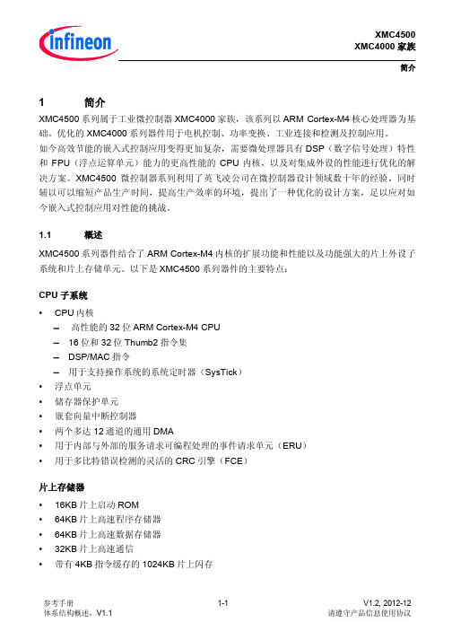
简介1 简介XMC4500系列属于工业微控制器XMC4000家族,该系列以ARM Cortex-M4核心处理器为基础。
优化的XMC4000系列器件用于电机控制、功率变换、工业连接和检测及控制应用。
如今高效节能的嵌入式控制应用变得更加复杂,需要微处理器具有DSP(数字信号处理)特性和FPU(浮点运算单元)能力的更高性能的CPU内核,以及对集成外设的性能进行优化的解决方案。
XMC4500微控制器系列利用了英飞凌公司在微控制器设计领域数十年的经验,同时辅以可以缩短产品生产时间,提高生产效率的环境,提出了一种优化的设计方案,足以应对如今嵌入式控制应用对性能的挑战。
1.1 概述XMC4500系列器件结合了ARM Cortex-M4内核的扩展功能和性能以及功能强大的片上外设子系统和片上存储单元。
以下是XMC4500系列器件的主要特点:CPU子系统•CPU内核−高性能的32位ARM Cortex-M4 CPU−16位和32位Thumb2指令集−DSP/MAC指令−用于支持操作系统的系统定时器(SysTick)•浮点单元•储存器保护单元•嵌套向量中断控制器•两个多达12通道的通用DMA•用于内部与外部的服务请求可编程处理的事件请求单元(ERU)•用于多比特错误检测的灵活的CRC引擎(FCE)片上存储器•16KB片上启动ROM•64KB片上高速程序存储器•64KB片上高速数据存储器•32KB片上高速通信•带有4KB指令缓存的1024KB片上闪存简介通信外设•以太网MAC模块,能够容纳10/100 MB/s的传输速率•通用串行总线,USB2.0主机,全速OTG,带有集成PHY•控制器局域网接口(MultiCAN),具有三节,64个消息对象,数据速率最高可达1 MB/s 的 Full-CAN/Basic-CAN•6个通用串行接口通道(USIC),可用作通用异步收发传输器(UART),双线与四线串行外设接口(SPI),IIC, IIS 与 LIN接口•用于人机交互的LED灯和触摸感应控制器(LEDTS)•用于储存数据的SD和多媒体卡接口(SDMMC)•外部总线接口单元(EBU)启用与外部储存设备以及片外外设通信,如SRAM,SDRAM,NOR,NAND和突发模式闪存。
Z8018033VEC中文资料(zilog)中文数据手册「EasyDatasheet - 矽搜」
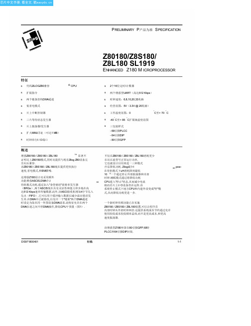
°C至+ 70 °C
s -40 °C至+ 85 °C扩展级温度范围
s 三包装样式 - 68引脚PLCC - 64引脚DIP - 80引脚QFP
概述
增强Z80180 / Z8S180 / Z8L180
™ 显著不
证明比上Z80180模式,同时还提供与现有Zilog Z80设备完
全向后兼容.
该Z80180 / Z8S180 / Z8L180现在提供更快执行
/NMNI /CN/C/INT/0INT/1INTS2T A0 A1 A2 A3 VSSA4 N/CA5 A6 A7 A8 A9 A10A11N/CN/CA12
图 4. Z80180 / Z8S180 / Z8L180 80引脚 QFP封装引脚配置
DS971800401
初稿
1-5
® CPU
Z80180/Z8S180/
Z8L180 SL1919
ENHANCED Z180 M ICROPROCESSOR
s 2个16位定时/计数器
s 两个增强型UART(高达512 Kbps)
s 时钟速度:6,8,10,20,33兆赫
s 经营范围:5V(3.3V @ 20兆赫)
s 工作温度范围:0
Zilog
ENHANCED Z180微处理器
CKA1//TEND0 CKA0//DREQ0
RXS/CTS1
/RFSNH/CN/C/HA/LTTEN/DDR1ECQKS1 TXS
RXA测1 试TXA1 N/C
RXAT0XA/0DCD/C0TS/R0TS0 D7 N/CN/CD6
1
64
60
55
50
/IORQ
TXA1 CKA1, /TEND0 RXA1
8205a芯片参数
8205a芯片参数
8205A 是一种四路运算放大器,广泛应用于电子系统中,例如充电宝、手机、电脑等。
它具有低失调电压、低噪声、低失真、大输出电流等特点。
在充电宝中,8205A 通常用于控制电池的充电和放电,以保持电池电压的稳定。
8205A 的参数如下:
- 输入电压范围:0.8V 至输入电压最大值
- 输出电压范围:0V 至输出电压最大值
- 输出电流:当输出电压为 3.6V 时,最大输出电流为 2A
- 失调电压:≤1mV
- 噪声电压:≤3mV
- 增益带宽积:≥5MHz
- 工作电流:置入电流≤5mA,输出电流≤2A
- 封装方式:SOT-23-5
要查询电子芯片的参数,可以下载一个集成电路查询软件,例如AIDA64 或 Integrated Collector。
这些软件可以查询各种元件的技术资料,包括芯片参数、电路图、供应商等。
此外,也可以在网上搜索相关的元件信息,例如在 TI 官网上搜索 8205A 芯片。
RC4580中文资料
元器件交易网元器件交易网IMPORTANT NOTICETexas Instruments Incorporated and its subsidiaries (TI) reserve the right to make corrections, modifications,enhancements, improvements, and other changes to its products and services at any time and to discontinueany product or service without notice. Customers should obtain the latest relevant information before placingorders and should verify that such information is current and complete. All products are sold subject to TI’s termsand conditions of sale supplied at the time of order acknowledgment.TI warrants performance of its hardware products to the specifications applicable at the time of sale inaccordance with TI’s standard warranty. T esting and other quality control techniques are used to the extent TIdeems necessary to support this warranty. Except where mandated by government requirements, testing of allparameters of each product is not necessarily performed.TI assumes no liability for applications assistance or customer product design. Customers are responsible fortheir products and applications using TI components. T o minimize the risks associated with customer productsand applications, customers should provide adequate design and operating safeguards.TI does not warrant or represent that any license, either express or implied, is granted under any TI patent right,copyright, mask work right, or other TI intellectual property right relating to any combination, machine, or processin which TI products or services are used. Information published by TI regarding third-party products or servicesdoes not constitute a license from TI to use such products or services or a warranty or endorsement thereof.Use of such information may require a license from a third party under the patents or other intellectual propertyof the third party, or a license from TI under the patents or other intellectual property of TI.Reproduction of information in TI data books or data sheets is permissible only if reproduction is withoutalteration and is accompanied by all associated warranties, conditions, limitations, and notices. Reproductionof this information with alteration is an unfair and deceptive business practice. TI is not responsible or liable forsuch altered documentation.Resale of TI products or services with statements different from or beyond the parameters stated by TI for thatproduct or service voids all express and any implied warranties for the associated TI product or service andis an unfair and deceptive business practice. TI is not responsible or liable for any such statements.Following are URLs where you can obtain information on other Texas Instruments products and applicationsolutions:Products ApplicationsAmplifiers Audio /audioData Converters Automotive /automotiveDSP Broadband /broadbandInterface Digital Control /digitalcontrolLogic Military /militaryPower Mgmt Optical Networking /opticalnetworkMicrocontrollers Security /securityTelephony /telephonyVideo & Imaging /videoWireless /wirelessMailing Address:Texas InstrumentsPost Office Box 655303 Dallas, Texas 75265Copyright 2004, Texas Instruments Incorporated。
典型DA转换DAC0832芯片4580
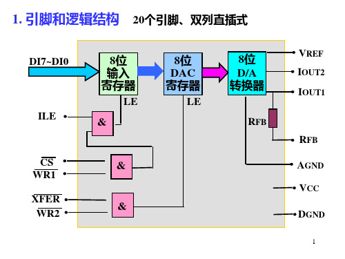
XFER
DGND AGND
13
PC总线
D7~D0
+5V
A9~A0
IOW
DI7~DI0
输入 寄存
ILE
LE
WR1 &
地 port1 CS
址
译 码
port2
XFER &
WR2
DAC 寄存
LE
D/A IOUT2 转换
+
Vo
IOUT1
-
RFB
转换一个数据的程序段:
MOV AL, data ;取数字量 MOV DX,port1 OUT DX, AL ;打开第一级锁存 MOV DX, port2 OUT DX, AL ;打开第二级锁存
• 双积分式A/D转换器组成: 积分器A1; 零电压比较器A2; 计数器; 控制逻辑; 标准电压等。
29
双积分式A/D转换
S2
V01
模拟输入
C
VX
S1
VN
标准电压
+ A1
V01 - 比较器 + A2
A/D启动 A/D结束
控制逻辑 ......
控制逻辑 ......
溢
清0
出 进
位
t0
t1
A/D启动 A/D结束
D0 ~ D7 +5V IOW
数据线
地 port1
A0
址
~
译 port2
A9
码
PC总线
DI0
RFB
~ DI7
IOUT1
-
ILE
IOUT2
+
Vo
WR1 WR2
转换一个数据的程序段:
- 1、下载文档前请自行甄别文档内容的完整性,平台不提供额外的编辑、内容补充、找答案等附加服务。
- 2、"仅部分预览"的文档,不可在线预览部分如存在完整性等问题,可反馈申请退款(可完整预览的文档不适用该条件!)。
- 3、如文档侵犯您的权益,请联系客服反馈,我们会尽快为您处理(人工客服工作时间:9:00-18:30)。
OCXO SERIES 8000 Rev. B
"FEATURES
Small OCXO in 1” SQ. package
Frequencies up to 38.880 MHz
AT and SC-Cut option
"ELECTRICAL PERFORMANCE
PARAMETER OCXO SERIES 8000
AT CUT CRYSTAL SC CUT CRYSTAL Supply voltage, nom. 5V ±5% Standard (3.3V, 12V Optional)
Power dissipation steady state 1.5 Watt Max.
Heat up power 3 Watt Max
Heat up time. 3 min Max
Frequency range 1 To 38.880 MHz Standard
Frequency Adjustment ±10PPM Min (0 to 5V) ±0.7PPM Min (0 to 5V)
±0.05 PPM ±0.1 PPM
±0.25 PPM ±0.01 PPM ±0.02 PPM ±0.03 PPM
Freq. stability vs. temperature
LX: 0°C to 60°C
FZ: -30°C to 70°C
D3: -40°C to 85°
(Standard, contact factory for different temp ranges and stabilities) Freq. stability vs. supply
changes
±0.015 PPM Max for ±5% Change ±0.010 PPM Max for ±5% Change Freq. stability vs. load changes ±0.01 PPM Max for ±5% Change ±0.005 PPM Max for ±5% Change
Long term stability (Aging) ±4 PPM Max for 10 Years
±0.005 PPM/Day Max. ±1 PPM Max for 10 Years ±0.002 PPM/Day Max.
Output HCMOS/TTL/Sine 0 to +7dBm (Low voltage CMOS Available)
Harmonics, Sub Harmonics -30dBc(Sine Output)
Spurious -75dBc(Sine
Output) Duty cycle 40/60% to 60/40%(HCMOS)
Rise / fall time 10nS Max. (HCMOS,10%~90%Vout, 90%~10%Vout)
Short term Stability (10MHz) 1 E-10 /Sec 5 E-11 /Sec
Phase Noise typical under static condition
(Sine Output 10MHZ) Offset Phase Noise
10Hz -90 dBc/Hz
100Hz -125 dBc/Hz
1000Hz -135 dBc/Hz
10000Hz -150 dBc/Hz
Offset Phase Noise
10Hz -110 dBc/Hz
100Hz -130 dBc/Hz
1000Hz -140 dBc/Hz
10000Hz -150 dBc/Hz
Note: All Typical parameters for a 10MHz output and 5V Supply, for different frequencies consult factory
" HOW TO ORDER (PART NUMBER)
Prefix Output Type Cut Type
Series Revision Temperature Range Stability Frequency Supply Voltage OX
2:HCMOS 4:LVCMOS 6:SINE
0:AT (No Vcontrol ) 1: SC (No Vcontrol )
4: AT (Elect Vcontrol) 5: SC (Elect Vcontrol)
80:8000
A
First letter Lowest Temperature,
Second letter Highest Temperature:
From A=-55°C to Z=+70°C, Then: 1=+75°C, 2=+80°C, 3=+85°C… in 5°C steps Example: LZ: +0°C to +70°C LX: +0°C to +60°C FZ: -20°C to +70°C FZ: -30°C to +70°C D3: -40°C to +85°C
Value x 10E-2 in PPM
Example 28=
0.28PPM 10= 0.1PPM
In MHZ
12:12V 5; 5V 3.3; 3.3V
HEIGHT, MAX. “H”: 0.52” / 13.2mm
OUTLINE TOLERANCE: ±0.015” / 0.4mm
PIN FUNCTIONS: [1] RF OUTPUT [2] GROUND
[3] N/C OR CONTROL VOLTAGE
[4] NOT CONNECTED [5] SUPPLY VOLTAGE。
