313LBPRCZFHCT中文资料
SNC313中文资料

Direct Drive Voice/Dual Tone Melody Controller 1 INTRODUCTIONSNC313 is a 1-channel voice synthesizer and dual-tone melody IC with PWM direct drive circuit. It built-in a 4-bit tiny controller with one 4-bit input port and two 4-bit I/O ports. By programming through the tiny controller in SNC313, user’s varied applications including voice section combination, dual-tone melody, key trigger arrangement, output control, and other logic functions can be easily implemented.2 FEATURESSingle power supply 2.4V – 5.5V7 seconds voice capacity are provided (@6KHZ sample rate)Built in a 4-bit tiny controllerOne 4-bit input port and two 4-bit I/O ports are provided128*4 bits RAM are provided24K*10 ROM size are provided for voice data and programMaximum 16k program ROM is providedReadable ROM code dataIR carrier signal is providedBuilt in a high quality speech synthesizerAdaptive playing speed from 2.5k-20kHz is providedOne voice channel plus Dual-Tone MelodyBuilt in a PWM Direct Drive circuit and a fixed current D/A outputSystem clock : 2MHzLow Power ResetDirect Drive Voice/Dual Tone Melody Controller 3 Block Diagram4 PIN ASSIGNMENTSymbol I/O Function DescriptionP13 ~ P10 I Bit3 ~ Bit0 of Input port 1P23 ~ P20 I/O Bit3 ~ Bit0 of I/O port 2P33 ~ P30 I/O Bit3 ~ Bit0 of I/O port 3VDD P Positive power supplyGND P Negative power supplyRST I Reset pin (active high)OSC O Oscillator / Crystal OutOutput of PWM or DA outputPositiveBUO1/VO OBUO2 O Negative Output of PWMDirect Drive Voice/Dual Tone Melody Controller5 FUNCTION DESCRIPTIONS 5.1. OscillatorSNC313 accept RC type oscillator for system clock. The typical circuit diagram for oscillator is listed as follow.rOSCVCCRC Oscillator5.2. ROMSNC313 contains substantial 24K words (10-bit) internal ROM. Program, voices and other data are shared with this same 24K words ROM.5.3. RAMSNC313 contains 128 nibbles RAM. The 128 nibbles RAM are divided into eight pages (page 0 to page 7, 16 nibbles RAM on each page). In our programming structure, users can easily define and locate RAM page in the program. For instance, users can use the instructions, PAGEn (n=0 to 7) to switch and indicate the RAM page. Besides, users can use direct mode, M0 ~ M15 in the data transfer type instructions, to access all 16 nibbles of each page.5.4. Power Down Mode“End” instruction will power down SNC313 and enable IC to consume fewer current for power saving. (<3uA @VDD=3V and <5uA @VDD=5V) Please be aware that when the power down mode is activated in SNC313, any valid data transition (L H or H L) occurring on any input port (P1) or IO ports (P2 and P3) will lead SNC313 back to normal operation mode.5.5. Sampling Rate CounterThe unique sampling rate counter is designed in voice channel to be able to play diverse voices at different sample playing rates. The playing rate can be adaptively set up among from the wide ranges of 2.5KHz to 20KHz. This feature makes voice close to its original source and yield the better voice quality.5.6. Dual-Tone GeneratorA dual-tone melody generator is included to generate 2-channel music songs with a pleasant square-wave-like timbre. The pitch range of each tone generator is as wide as 4 octaves (48 different notes totally). The output of dual-tone generator can be mixed with the output of voice synthesizer to achieve voice playing with BGM (background music). Additionally, Sonix provides a numbered-musical-notation representation to help users compose their songs. Further, a MIDI (1.0) file translator can convert MIDI files into Sonix format.5.7. I/O PortsP1 is a 4-bit input port and P2/P3 are two 4-bit I/O ports. Any bit of P2 and P3 can be programmed as either input or output port individually. Any valid data transition (H L or L H) of P1, P2 and P3 can reactivate the chip when the chip is in power-down mode.Input Port Configuration (P10~P13)I/O Port Configuration (P20~P23, P30~P33)Note: weak N-MOS’s can serve as pull-low resistor.5.8. IR FunctionP33 can be modulated with 38.5KHz square wave before sent out to P33 pin. The IR signal can be achieved by this modulated signal.5.9. DAC & PWMSNC313 is an advanced chip to be designed having two optimal methods to play out the voices. One is DAC and the other is PWM. Upon user’s applications, user can select either DAC or PWM in his design. Please be aware that only one method can be activated at a time.DAC: A 7-bit current type digital-to-analog converter is built-in SNC313. The relationship between input digital data and output analog current signal is listed in the following table. Also, the recommended application circuit is illustrated as follows.Input data Typical value of output current (mA)0 01 3/127…N n*(3/127)…127 3DAC outputPWM: A PWM (pulse width modulation) circuit is built-in SNC313. PWM can convert input digital data into pulse trains with suitable different pulse width. The maximum resolution of PWM is 7 bits. Two huge output stage circuits are designed in SNC313. With this advanced circuit, the chip is capable of driving speaker directly without external transistors. The recommended application circuit is illustrated as follows.PWM OutputDirect Drive Voice/Dual Tone Melody Controller 6 ABSOLUTE MAXIMUM RATINGItems Symbol Min Max Unit.Supply Voltage V DD-V -0.3 6.0 VInput Voltage V IN V SS-0.3 V DD+0.3 VOperating Temperature T OP 0 55.0 o CStorage Temperature T STG -55.0 125.0 o C7 ELECTRICAL CHARACTERISTICSItem Sym. Min. Typ. Max. Unit Condition Operating Voltage V DD 2.4 3.0 5.5 VStandby current I SBY - 2.05.0 - u A V DD=3V , no loadV DD=4.5V, no loadOperating Current I OPR - 300700 - u A V DD=3V , no loadV DD=4.5V, no loadInput current ofP1, P2, P3I IH - 3.0 10.0 u A V DD=3V,V IN=3VDrive current ofP2, P3I OD- 4 - m A V DD=3V,V O=2.4VSink Current ofP2, P3I OS- 6 - m A V DD=3V,V O=0.4VDrive current ofP2, P3I OD- 5 - m A V DD=4.5V,V O=3.9VSink Current ofP2, P3I OS- 9 - m A V DD=4.5V,V O=0.4V Drive current of Buo1 I OD 100 120 - m A VDD=3V,Buo1=1.5V Sink Current of Buo1 I OS 100 120 - m A VDD=3V,Buo1=1.5V Drive Current of Buo2 I OD 100 120 - m A VDD=3V,Buo2=1.5V Sink Current of Buo2 I OS 100 120 - m A VDD=3V,Buo2=1.5V Oscillation Freq. F OSC - 2.0 - MHzV DD=3VIR Carrier Frequency Fir - 38.5 - KHz Fosc=2MHzDirect Drive Voice/Dual Tone Melody Controller 8 ROSC PerformanceROSC frequency vs VDD (Typical value, R=120KΩ)ROSC frequency vs. VDD (For various R)Direct Drive Voice/Dual Tone Melody Controller 9 APPLICATION CIRCUITD/A Speaker Output16 Scan KeysNote: The C1 (0.1uF) between Power and GND should be closed to VDD pin of SNC313 as possible.Direct Drive Voice/Dual Tone Melody Controller10 BONDING PAD12345678910111213141516171819P10P11P12P13P20P21OSCG N DB U O 1V D DB U O 2G N D P22P23P30P31P32P33RST (0.00,0.00)SNC313Note: The substrate MUST be connected to Vss in PCB layout.Direct Drive Voice/Dual Tone Melody Controller DISCLAIMERThe information appearing in SONiX web pages (“this publication”) is believed to be accurate.However, this publication could contain technical inaccuracies or typographical errors. The reader should not assume that this publication is error-free or that it will be suitable for any particular purpose. SONiX makes no warranty, express, statutory implied or by description in this publication or other documents which are referenced by or linked to this publication. In no event shall SONiX be liable for any special, incidental, indirect or consequential damages of any kind, or any damages whatsoever, including, without limitation, those resulting from loss of use, data or profits, whether or not advised of the possibility of damage, and on any theory of liability, arising out of or in connection with the use or performance of this publication or other documents which are referenced by or linked to this publication.This publication was developed for products offered in Taiwan. SONiX may not offer the products discussed in this document in other countries. Information is subject to change without notice. Please contact SONiX or its local representative for information on offerings available. Integrated circuits sold by SONiX are covered by the warranty and patent indemnification provisions stipulated in the terms of sale only. The application circuits illustrated in this document are for reference purposes only. SONIX DISCLAIMS ALL WARRANTIES, INCLUDING THE WARRANTY OF MERCHANTABILITY OR FITNESS FOR ANY PURPOSE. SONIX reserves the right to halt production or alter the specifications and prices, and discontinue marketing the Products listed at any time without notice. Accordingly, the reader is cautioned to verify that the data sheets and other information in this publication are current before placing orders.Products described herein are intended for use in normal commercial applications. Applications involving unusual environmental or reliability requirements, e.g. military equipment or medical life support equipment, are specifically not recommended without additional processing by SONIX for such application.Direct Drive Voice/Dual Tone Melody Controller。
3132中文资料
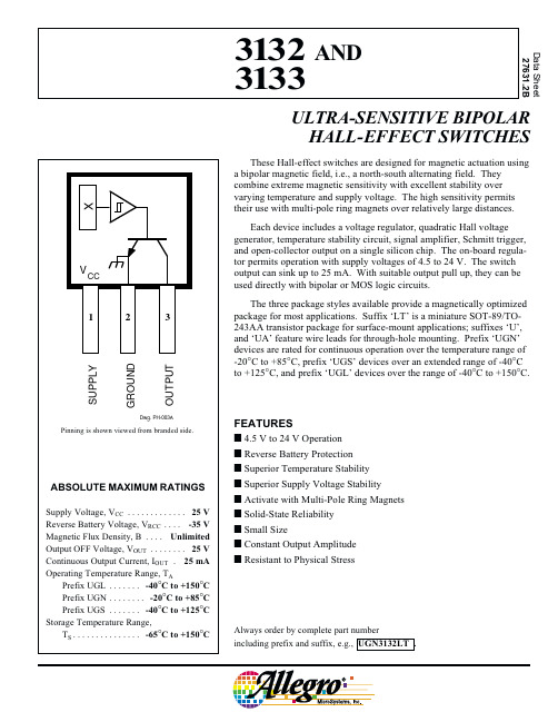
Units G G G G G
FEATURES I 4.5 V to 24 V Operation I Reverse Battery Protection I Superior Temperature Stability I Superior Supply Voltage Stability I Activate with Multi-Pole Ring Magnets I Solid-State Reliability I Small Size I Constant Output Amplitude I Resistant to Physical Stress
—
-20
—
52
—
NOTE: As used here, negative flux densities are defined as less than zero (algebraic convention.) Typical values are at TA = +25°C and VCC = 12 V.
Characteristic Operate Point
Release Point
Hysteresis
Symbol BOP
BRP
Bhys
Device Type* 3132 3133 3132 3133 Both
Min. — — -95 -75 30
Limits
SAMPO GK-313 说明书

GK-313SAMPO行動電話機使用手冊目錄1 前言 (7)1.1 簡介 (7)1.2 安全須知 (8)1.3 安全警告和注意事項 (9)1.3.1通用注意事項 (9)1.3.2使用手機的注意事項 (9)1.3.3使用電池的注意事項 (12)1.3.4使用充電器的注意事項 (13)1.3.5清潔和維護 (14)1.3.6一般注意事項 (15)2使用前 (16)2.1 名稱和說明 (16)2.1.1規格 (16)2.1.2按鍵說明 (17)2.1.3側鍵功能介紹 (19)2.2 電池 (19)2.2.1電池的拆卸和安裝 (19)2.2.2電池的充電 (20)2.3 連接網路 (22)12.3.3開關話機 (23)2.3.4 SIM卡的去鎖 (23)2.3.5話機解鎖 (24)2.3.6連接到網路 (25)3基本操作 (26)3.1 撥打電話 (26)3.1.1撥打國內電話 (26)3.1.2撥打固定電話分機 (26)3.1.3撥打國際電話 (27)3.1.4撥打列表中電話 (28)3.2 緊急呼叫 (28)3.3 接聽電話 (29)3.4 通話記錄 (29)3.5 呼叫菜單 (29)4功能表 (32)4.1 功能表的使用 (32)4.1.1搜索選擇功能 (32)4.1.2快捷選擇功能 (32)4.1.3導航鍵功能 (33)24.3 電話簿 (37)4.4 訊息 (39)4.4.1新訊息 (39)4.4.2 寫訊息 (39)4.4.3 查看已接收訊息和已保存訊息 (41)4.4.4常用範本的操作 (43)4.4.5 訊息設定 (43)4.4.6 多媒體訊息 (44)4.4.7 聊天 (46)4.4.8 語音郵件 (47)4.4.9 廣播訊息 (47)4.5 通話記錄 (47)4.5.1 查看通話列表 (47)4.5.2輔助選單 (48)4.6 設定 (50)4.6.1 話機設定 (50)4.6.2 通話設定 (52)4.6.3 網路設定 (53)4.6.4 安全設定 (52)4.6.5 恢復原廠設定 (55)4.6.6音效 (55)34.7.2相簿 (56)4.7.3動畫錄影器 (57)4.7.4動畫播放器 (57)4.7.5照片藝術家 (57)4.7.6音樂播放器 (58)4.7.7錄音 (59)4.7.8鈴聲編輯 (59)4.8 檔案管理 (60)4.9 娛樂和遊戲 (60)4.9.1遊戲 (60)4.9.2碼錶 (61)4.9.4遊戲設定 (61)4.10 情境模式 (61)4.10.1一般模式 (61)4.10.2會議模式 (62)4.10.3戶外模式 (62)4.10.4室內模式 (63)4.10.5耳機模式 (63)4.11 行動祕書 (63)4.11.1 日曆 (63)4.11.2 待辦事項 (64)44.12 網路服務 (64)4.12.1 STK (64)4.12.2 WAP (65)4.12.3 帳號資料 (66)4.13 附加功能 (67)4.13.1 計算機 (67)4.13.2 單位換算 (67)4.13.3 貨幣換算 (68)4.13.4 健康管理 (68)4.14 快捷功能 (69)4.15 T-FLASH卡的使用 (69)4.15.1 T-flash卡的拆裝 (69)4.15.2 T-flash卡的使用 (70)5輸入法 (71)5.1 概述 (71)5.2 鍵盤定義 (71)5.3 輸入法說明 (72)5.3.1拼音輸入法 (72)5.3.2筆劃輸入法 (74)5.3.3 智慧英文輸入法 (76)56附錄一 (79)6.1 常見故障診斷 (79)7附錄二 (80)7.1 縮略語及其解釋 (80)8附錄三 (81)8.1 手機配件使用注意事項 (81)8.2 電池 (81)8.2.1充電器 (82)8.2.2USB (82)8.3 保固條款 (82)8.2 維修中心 (85)61 前言1.1 簡介感謝您選擇SAMPO GK-313系列行動電話。
GlobalSat TR-313 用户手册说明书
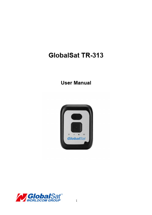
GlobalSat TR-313 User ManualTABLE OF CONTENTS1. Warning (3)2. Welcome (4)3. Introduction and Features (5)3.1 Introduction (5)3.2 LED Indicators (6)4. Device Operation (7)4.1 Device charging (7)4.2 SIM card Installation (8)4.3 Power (9)4.4 Emergency button (10)5. Contact Information (11)6. Safety Information (11)7. Limited Warranty (12)USE RESPONSIBLY. READ ALL INSTRUCTIONS ANDSAFETY INFORMATION BEFORE USE.Globalsat Worldcom Corporation / USGlobalsat, Inc., will not accept any responsibility whatsoever for accidents or violations of local Laws resulting from failure to observe common sense precautions and local laws. Your personal judgment, traffic regulations,and common sense must always take precedence over any directions produced by GPS receiver or the mapping software.Indemnification:User agrees to defend, indemnify and hold harmless GlobalSat WorldCom Corp. and USGlobalsat, Inc., its officers, directors, employees and agents against and from any third party claims, actions, damages or demands, including but not limited to, reasonable legal and accounting fees, resulting from user's use or misuse of this product, violation of these Terms, or any activities related to this product, or from user's violations of the rights of any other user of this product. Use of this Product is at user's own risk.Thank you for purchasing the GlobalSat TR-313. The TR-313 is a sleek, compact and feature rich Personal / Personnel tracking device. In addition to its telemetry abilities, the TR-313 unit incorporates a wide array of custom feature, functions and configurations for unique client requirements. TR-313 is a versatile device which can be used for many Personal & Personnel tracking applications. We appreciate your purchase of a GlobalSat Worldcom Product!3.1 IntroductionTR-313 is a 3G personal tracking device with fast GPS acquisition time. It is compact, portable and stylish in design capable to connect both GSM and GPRS wireless networks. Users can easily and remotely configure TR-313 and display GPS locations on remote monitoring / tracking platforms.3.2 LED IndicatorsPower Status LEDGSM LEDGPS LEDBluetooth LED (Optional function)Note: The TR313 BLE-enabled devices must be an authorized andpre-integrated TR-313 accessory in order to connect, not all BLE devices willconnect without pre-integration.4.1 Device charging1 2 3Using the device for the first time, rechargeable battery will require a complete 100% charge before TR-313 is operable. To maximize your device’s battery life, proceed by performing the steps listed below.1. Place the device on the charging cradle.2. Connect the Micro USB side of the cable to the cradle port and connect the otherend of the cable to the designated AC power source (USB/AC adaptor).3. Allow at least 6 hours of battery charging time.4.2 SIM Card Installation1 2 31. Unscrew the SIM card cover.2. Remove the cover.3. With the metal contacts facing down, with the notch of the SIM card positioned toyour lower left side as seen in the above #3 image, place the SIM card onto the SIM card compartment.4. Replace the back cover in its original compartment and re-screw the cover. Note: Before installing or taking out the SIM card, please power off the device.4.3 Power1. To turn the device “ON”, press and hold the power button for 1 second.2. To turn the device “OFF”, press and hold the power button for 3 seconds until thedevice vibrates.3. To perform a hard reset, press and hold the power button for 8 to 10 seconds.4. For developers accessing COM port connection from the device, press the powerbutton once quickly while the device is sitting on the cradle with the USB cable connected to PC.4.3 Emergency button1. While pressing and holding the emergency button, TR-313 will send the emergency SMS messages to pre-programmed phone numbers and continuously dial out to these phones numbers until one phone call is picked up. Call rotary.2. Once the emergency call is answered, the user and the contact may speak through the hands-free speakerphone.3. By default TR-313 allows the user to end a call by pushing the emergency button once.4. Users may also answer incoming phone calls by pushing the emergency button once when TR-313 exhibits ring tones.Note: .Please contact Technical Support for programming emergency phone numbers.GlobalSat WorldCom CorporationAddress: 16F., No.186, Jian 1st Rd., Jhonghe Dist., New Taipei City ,Taiwan TEL: +886-2-82263799 FAX: +886-2-82263899Please consult your airline prior to the operation of this product in the aircraft. . Operating this product in environments emitting intensive radio waves or radiation can affect the operation and functionality of this product.Avoid use in humid or rainy environment. Water ingress can disable or destroy this product beyond repair.Avoid using this product in a dusty environment. Dust ingress can compromise the products ability to function.Avoid situations that include Over-voltage, over charging, power cable damage may cause overheating or potential fire disaster.Never use any chemical or detergent to clean the Personal Tracker to prevent erosion of the surface or paintwork.In order to eliminate the risk of electric shock, make certain the charging cable is completely inserted / seated, do not touch the power cable plug / connectors with wet or damp hands.Do not charge the Device in any extreme cold or hot temperatures, which may cause damage to the device.Keep out of the reach of children during charging.Avoid direct prolonged exposure to sunlight and high temperatures to avoid the potential over-heating of the battery of this product, which may cause damage.Please do not attempt to repair this device yourself, contact Globalsat or USGlobalSat for Technical Support.Keep all the wires tidy in order to prevent damage or tangling.Globalsat/USGlobalsat (1) Year Limited WarrantyFOR CONSUMERS, WHO ARE COVERED BY CONSUMER PROTECTION LAWS OR REGULATIONS IN THEIR COUNTRY OF PURCHASE OR, IF DIFFERENT, IN THEIR COUNTRY OF RESIDENCE, THE BENEFITS CONFERRED BY THIS WARRANTY ARE IN ADDITION TO ALL RIGHTS AND REMEDIES CONVEYED BY SUCH CONSUMER PROTECTION LAWS AND REGULATIONS. THIS WARRANTY DOES NOT EXCLUDE, LIMIT OR SUSPEND ANY RITGHTS OF CONSUMERS ARISING OUT OF NONCONFORMITY WITH A SALES CONTRACT. SOME COUNTRIES, STATES AND PROVINCES DO NOT ALLOW THE EXCLUSION OR LIMITATION OF INCIDENTAL OR CONSEQUENTIAL DAMAGES OR ALLOW LIMITATIONS ON HOW LONG AN IMPLIED WARRANTY OR CONDITION MA Y LAST, SO THE LIMITATIONS OR EXCLUSIONS DESCRIBED BELOW MAY NOT APPLY TO YOU. THIS WARRANTY GIVES YOU SPECIFIC LEGAL RIGHTS, AND YOU MAY ALSO HAVE OTHER RIGHTS THAT VARY BY COUNTRY, STATE OR PROVIDENCE. THIS LIMITED WARRANTY IS GOVERNED BY AND CONSTRUED UNDER THE LAWS OF THE COUNTRY IN WHICH PRODUCT PURCHASE TOOK PLACE. GLOBALSAT/ USGLOBALSAT, THE WARRANTOR UNDER THIS LIMITED WARRANTY, IS IDENTIFIED AT THE END OF THIS DOCUMENT ACCORDING TO THE COUNTRY OR REGION IN WHICH THE PRODUCT PURCHASE TOOK PLACE.G lobalsat/ USGlobalsat’s warranty obligations for this hardware product are limited to the terms set forth below:Globalsat/ USGlobalsat, as defined below, warrants this hardware product against defects in materials product hardware against manufacturing defects in materials and workmanship under normal use for aperiod of ONE (1) year from the date of retail purchase by the original end-user purchaser and purchased from a recognized “authorized dealer”(“Warranty Period”).Products purchased from any unauthorized source, such as unauthorized e-Bay resellers, will not qualify for free warranty service/support and may require the end-user to pre-pay fees associated with, but not limited to the support, repair, replacement and shipping of the product to and from the service center. If a hardware defect arises and a valid claim is received by Globalsat/ USGlobalsat within the Warranty Period, at its option and to the extent permitted by law, Globalsat/ USGlobalsat will either (1) repair the product at no charge, using new parts or parts equivalent to new in performance and reliability, (2) exchange the product with a product that is new orequivalent to new in performance and reliability and is at least functionally equivalent to the original product or, (3) refund the purchase price of the product. Globalsat/ USGlobalsat may request that you replace defective parts with new or refurbished user-installable parts that Globalsat/ USGlobalsat provides in fulfillment of its warranty obligation. A replacement product or part, including a user-installable part that has been installed in accordance with instructions provided by Globalsat/ USGlobalsat, assumes the remaining warranty of the original product or ninety (90) days from the date of replacement or repair, whichever provides longer coverage for you. When a product or part is exchanged, any replacement item becomes your property and the replaced items becomes Globalsat/ USGlobalsat’s property. Parts provide by Globalsat/ USGlobalsat in fulfillment of its warranty obligation must be used in products for which warranty service is claimed. When a refund is given, the product for which the refund is provided must be returned to Globalsat/ USGlobalsat and becomes Globalsat/ USGlobalsat’s property.If a defect arises and a valid claim is received by Globalsat/ USGlobalsat after the first one hundred and eighty (180) days of Warranty period, a shipping and handling charge may apply to any repair or exchange of the product undertaken by Globalsat/ USGlobalsat.EXCLUSIONS AND LIMITATIONSThis Limited Warranty applies only to the hardware product manufactured by or for Globalsat that can be identified by the “Globalsat” trademark, trade name, or logo annexed to it. The Limited Warranty does not apply to any non-Globalsat hardware product or any software, even if packaged or sold with the Globalsat hardware.Manufacturers, suppliers, or publishers, other than Globalsat/ USGlobalsat, may provide their own warranties to the end user purchaser, but Globalsat/ USGlobalsat, in so far as permitted by law, provides their products “as-is”. Software distributed by Globalsat/ USGlobalsat with or without the Globalsat brand name (including, but not limited to system software) is not covered under this Limited Warranty. Refer to the licensing agreement accompanying the software for details of your rights with respect to its use. Globalsat/ USGlobalsat does not warrant that the operation of the product will be uninterrupted or error-free. Globalsat/USG lobalsat is not responsible for damage arising from failure to follow instructions relating to the product’s use.This warranty does not apply: (a) to consumable parts, such as batteries, unless damage has occurred due to a defect in materials and workmanship; (b) to cosmetic damage, including but notlimited to scratches, dents, and broken plastic on ports; (c) to damage cause by use accident, abuse, misuse, flood, fire, earthquake or other external causes; (e) to damage caused by operating the product outside the permitted or intended uses described by Globalsat/ USGlobalsat; (f) to damage caused by service (including upgrades and expansions) performed by anyone who is not a representative of Globalsat/ USGlobalsat or an Globalsat/ USGlobalsat authorized service provider;(g) to a product or part that has been modified to alter functionality or capability without the written permission of Globalsat/ USGlobalsat; or (h) if any Globalsat/ USGlobalsat serial number has been removed or defaced.IMPORTANT: Do not open the hardware product. Opening the hardware product may cause damage that is not covered by this warranty. Only Globalsat/ USGlobalsat or an authorized service provider should perform service on this hardware product.TO THE EXTENT PERMITTED BY LAW, THIS WARRANTY AND THE REMEDIES SET FORTH ABOVE ARE EXCLUSIVE AND IN LIEU OF ALL OTHER WARRANTIES, REMEDIES AND CONDITIONS, WHETHER ORAL OR WRITTEN, STATUTORY, EXPRESS OR IMPLIED. AS PERMITTED BY APPLICABLE LAW, GLOBALSAT/ USGLOBALSAT SPECIFICALLY DISCLAIMS ANY AND ALL STATUTORY OR IMPLIED WARRANTIES, INCLUDING, WITHOUT LIMITATION, WARRANTIES OF MERCHANTIBILITY AND FITNESS FOR A PARTICULAR PURPOSE AND WARRANTIES AGAINST HIDDEN OR LATENT DEFECTS. IF GLOBALSAT/ USGLOBALSAT CANNOT LAWFULLY DISCLAIM STATUTORY OR IMPLIED WARRANTIES THEN TO THE EXTENT PERMITTED BY LAW, ALL SUCH WARRANTIES SHALL BE LIMITED IN DURATION OF THE EXPRESS WARRANTY AND TO THE REPAIR OF REPLACEMENT SERVICE AS DETERMINED BY GLOBALSAT/ USGLOBALSAT IN ITS SOLE DISCRETION.No Globalsat/ USGlobalsat reseller, agent, or employee is authorized to make any modifications, extension, or addition to this warranty. If any term is held to be illegal or unenforceable, the legality or enforceability of the remaining terms shall not be affected or impaired.EXCEPT AS PROVIDED IN THIS WARRANTY AND TO THE MAXIMUM EXTENT PERMITTED BY LAW, GLOBALSAT/ USGLOBALSAT IS NOT RESPONSIBLE FOR DIRECT, SPECIAL, INCIDENTAL OR CONSEQUENTIAL DAMAGES RESULTING FROM ANY BREACH OF WARRANTY OR CONDITION, OR UNDER ANY OTHER LEGAL THEORY, INCLUDING BUT NOT LIMITED TO LOSS OF USE; LOSS OF REVENUE; LOSS OF ACTUAL OR ANTICIPATED PROFITS (INCLUDING LOSS OF PROFITS ON CONTRACTS); LOSS OF THE USE OF MONEY; LOSS OF ANTICIPATED SAVINGS; LOSS OF BUSINESS; LOSS OF OPPORTUNITY; LOSS OF GOODWILL; LOSS OF REPUTATION; LOSS OF;DAMAGE TO OR CORRUPTION OF DATA; OR ANY INDIRECT OR CONSEQUENTIAL LOSS OR DAMAGE HOWSOEVER CAUSED INCLUDING THE REPLACEMENT OF EQUIPMENT AND PROPERTY, ANY COSTS OF RECOVERING, PROGRAMMING OR REPRODUCING ANY PROGRAM OR DATA STORED IN OR USED WITH THE GLOBALSAT/ USGLOBALSAT PRODUCT AND ANY FAILURE TO MAINTAIN THE CONFIDENTIALITY OF DATA STORED ON THE PRODUCT. THE FOREGOING LIMITATION SHALL NOT APPLY TO DEATH OR PERSONAL INJURY CLAIMS, OR ANY STATUTORY LIABILITY FOR INTENTIONAL AND GROSS NEGLIGENT ACTS AND/OR OMISSIONS. GLOBALSAT/ USGLOBALSAT DISCLAIMS ANY RESPRESENTATION THAT IT WILL BE ABLE TO REPAIR ANY PRODUCT UNDER THIS WARRANTY OR MAKE A PRODUCT EXCHANGE WITHOUT RISK TO OR LOSS OF PROGRAMS OR DATA.OBTAINING WARRANTY SERVICEPlease access and review the online help resources referred to in the documentation accompanying this hardware product before seeking warranty service. If the product is still not functioning properly after making use of these resources, access the online website for instructions on how to obtain warranty service. You must follow Globalsat/ USGlobalsat warranty processes. Globalsat/ USGlobalsat may provide warranty service (i) by sending the unit to Globalsat/ USGlobalsat location, where service is performed at the location, or (ii) by sending the unit to an authorized Globalsat/ USGlobalsat supplier (iii) by sending you new or refurbished customer-installable replacement product or parts to enable you to service or exchange your own product (“RMA service”). Upon receipt of the replacement product or part, the original product or part becomes the property of Globalsat/ USGlobalsat and you agree to follow instructions, including, if requires, arranging the return of the product or part to Globalsat/ USGlobalsat in a timely manner. When providing RMA service requiring the return of the original product or part, Globalsat/ USGlobalsat may require credit card authorization as security for the retail price of the replacement product or part and applicable shipping costs. If you follow the instructions, Globalsat/ USGlobalsat will cancel the credit card authorization, so you will not be charged for the product or part and shipping costs. If you fail to return the replace product or part as instructed, Globalsat/ USGlobalsat will charge the credit card for the authorized amount. Service options, parts availability and response times may vary according to the country in whichservice is requested. Service options are subject to change at any time. You may be responsible for shipping and handling charges if product cannot be serviced in the country in which service is requested. If you seek service in a country that is not the country of purchase, you will comply with applicable export laws and regulations and be responsible for all custom duties, V.A.T. and other associated taxes and charges. For international service, Globalsat/ USGlobalsat may repair or exchange defective products and parts withcomparable products and parts that comply with local standards. In accordance with applicable law, Globalsat/ USGlobalsat may require that you furnish proof of purchase details and/ or comply with the registration requirements before receiving warranty service.Please refer to the accompanying documentation for more details on this and other matters obtaining warranty service.Globalsat/ USGlobalsat will maintain and use customer information in accordance with the Globalsat/ USGlobalsat Privacy Policy.If your product is capable of storing software programs, data and other information, you should make periodic backup copies of the information contained on the product’s hard drive or other storage media to protect the contents and as a precaution against possible operational failures. Before you deliver your product for warranty service it is your responsibility to keep a separate backup copy of the contents, and disable any security passwords. IT IS POSSIBLE THAT THE CONTENTS OF YOUR HARD DRIVE WILL BE LOST OR REFORMATTED IN THE COURSE OF WARRANTY SERVICE, AND GLOBALSAT/ USGLOBALSAT AND ITS AGENTS ARE NOT RESPONSIBLE FOR ANY DAMAGE TO OR LOSS OF PROGRAMS, DATA OR OTHER INFORMATION CONTAINED ON THE MEDIA OR ANY PART OF THE PRODUCT SERVICED. Your product will be returned to you configured as originally purchased, subject to applicable updates. You will be responsible for reinstalling all other software programs, data and passwords. Recovery and reinstallation of service programs and user data are not covered under this Limited Warranty.。
XP313使用手册
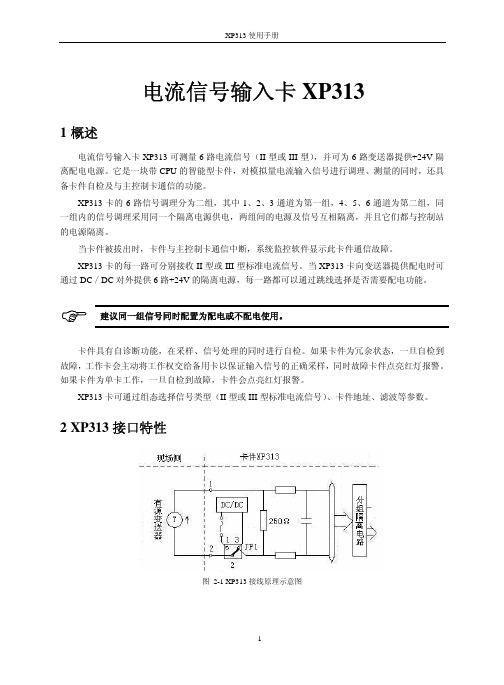
端子定义
配电
不配电
CH1+ CH1- CH2+ CH2- CH3+ CH3-
NC NC CH4+ CH4- CH5+ CH5- CH6+ CH6- NC NC
CH1CH1+ CH2CH2+ CH3CH3+
NC NC CH4CH4+ CH5CH5+ CH6CH6+ NC NC
备注 第一通道 第二通道 第三通道
2-3
2-3
2-3
配电设置跳线(JP1~JP6)
需要配电 不需配电
第一路 JP1 1-2 JP1 2-3
表 4-4 配电跳线
第二路 JP2 1-2 JP2 2-3
第三路 JP3 1-2 JP3 2-3
第四路 JP4 1-2 JP4 2-3
第五路 JP5 1-2 JP5 2-3
第六路 JP6 1-2 JP6 2-3
第四通道 第五通道 第六通道
CHX+表示第 X 通道正端,CHX-表示第 X 通道负端。例如第 1 通道的正、负端为:CH1+、 CH1-。NC 表示该端子不接线。
3
XP313 使用手册
4.4 跳线设置
冗余设置跳线(J2~J5)
表 4-3 冗余跳线
J2
J4
J5
卡件单卡工作
1-2
1-2
1-2
卡件冗余配置
XP313 卡件电源
(5±0.3)VDC,Imax<50mA (24±0.5)VDC,Imax<200mA 输入回路
6路 电流信号(Ⅱ型或Ⅲ型),组态可选
组态可选 15bit,带极性
250Ω 光电隔离,分组隔离 500VAC 1 分钟(现场侧与系统侧) 250VAC 1 分钟(组组之间)
东芝复印机英文缩写说明

东芝英文缩写说明ADF ........................................ 自动输稿器ADU ........................................ 自动双面器APS ........................................ 自动纸型选择AMS ........................................ 自动倍率选择APC ........................................ 自动电源控制API ........................................ 应用程序接口BYPASS ........................................ 旁路(手送供纸)CCD ........................................ 电荷耦合器/光电转换器CM ........................................ 纸盒组件CODEC ........................................ 编码解码器DDNS ........................................ 动态域名服务DF ........................................ 输稿器DRAM ........................................ 动态随机存储器DPI ........................................ 点/英寸Firmware ........................................ 固化程序FQDN ........................................ 完全合格域名HPF ........................................ 高通滤波器HVPS ........................................ 高压板HSYNC ........................................(激光单元)水平同步检测IGBT ........................................ 绝缘栅双极性晶体管I/F ........................................ 接口IPC ........................................(复印机与整理器之间)接口板IVSYNC ........................................ 图象垂直同步LDAP ........................................ 轻量目录存取协议LCD ........................................ 液晶显示屏LED ........................................ 发光二极管LSI ........................................ 大规模集成电路LSU ........................................ 激光单元LVDS ........................................ 低电压差分信号LVPS ........................................ 低压电源板NCP ........................................ Netware 核心协议NDS ........................................ Netware 目录服务NVRAM ........................................ 非易失性随机访问存储器MIB ........................................ 管理信息基础系统MIME ........................................ 多用途网际邮件扩充协议PLL ........................................ 相位锁定环路PM ........................................ 定期保养PFP........................................ 供纸工作台PWM ........................................ 脉冲宽度调制RADF ........................................ 翻转(双面)自动输稿器RFC ........................................ 请求注解RTC ........................................ 实时时钟SFB ........................................ 旁路(手送)供纸SLP ........................................ 服务定位协议SNMP ........................................ 简单网络管理协议SRAM ........................................ 静态随机存储器STP ........................................ 装订器WINS ........................................ Windows 网名服务英文缩写说明。
313LBPNCZFHGG中文资料

WIRING CODE
313L Red Green White Black Blue Brown Shield + Excit./Signal NC NC - Excit./Signal NC Option GH NC Option GH Open
Some options will affect dimensions. Consult factory if important. Note: Altering option codes will alter the unit length.
FLATS
1/2 NPT CONDUIT FITTING
1.0" DIA. REF.
BREATHER TUBE
1.00" 6.1 REF.
SUBMERSIBLE CABLE
2770 Long Road, Grand Island, NY 14072 USA Tel. (716) 773-9300 • Fax (716) 773-5019 • E-mail: sales@ • Website:
with Option LJ tapered inlet with stand off plate
ORDERING GUIDE
Ordering: Specify model, and pressure range and indicate modifications or accessories required. Use the following codes to identify desired item. Example 313L-B-PZ-LJ MODEL SERIES RANGE OPTIONS
Standard
PRESSURE RANGES:
S331C中文说明书

Site MasterS113C,S114C,S331C,S332C,天线、电缆和频谱分析仪用户指南专门用于传输线和其它射频器件的手持式测试仪目录第一章—概述简介………………………………………………………………..1-1说明………………………………………………………………..1-1标准附件……………………………………………………………1-1选件…………………………………………………………………1-2可选附件……………………………………………………………1-2性能指标…………………………………………………………..1-3维护事项……………………………………………………………1-6校准…………………………………………………………………1-6自动校准InstaCal 模块…………… ………………………………1-7年检………………………………………………………………….1-7第二章—功能和操作简介…………………………………………………………….…….2-1测试连接器面板…………………………………………………….2-1前面板概述………………………………………………………….2-2功能区硬键……………………………………………………………2-3 键盘区硬键…………………………………………………………2-4软键…. ………………………………………………………………2-6功率监测菜单……………………………………………………….2-15符号………………………………………………………………….2-19自检………………………………………………………………….2-19错误代码…………………………………………………………….2-19 自检错误…………..…………………………………………….2-19范围错误……..………………………………………………….2-21自动校准InstaCal错误消息………….…………………………2-22 电池信息…………………………………………….………………2-24新电池充电…………………………………………………………2-24 在Site Master上给电池充电…………………………………….2-24用充电器给电池充电………………………………………………2-24电池充电指示……………………………………………………2-25电池寿命…………………………………………………………..2-25关于电池的重要信息……………………………………………..2-26第三章—操作入门简介…………………………………………………………3-1开机过程……………………………………………………3-1选择频率/距离………………………………………………3-2校准…………………………………………………………..3-2校准确认……………………………………………….3-3手动校准过程………………………………………….3-4自动校准InstaCal 模块确认…………………………3-5自动校准InstaCal模块校准过程……………………. 3-6有测试端口延长电缆的校准………………………3-6 设臵刻度…………………………………………………3-7 自动刻度……………………………………………….3-7幅度刻度………………………………………………3-7 保存和调用设臵………………………………………….3-7 保存设臵……………………………………………...3-7调用设臵……………………………………………..3-8 保存和调用显示…………………………………………3-8 保存显示…………………………………………….3-8调用显示……………………………………………3-8设臵距离和电缆类型……………………………..3-9 改变单位…………………………………………………..3-9改变显示语言……………………………………………..3-9打印………………………………………………………..3-10 打印屏幕……………………………………………..3-10打印机开关设臵……………………………………..3-11 使用软背包……………………………………………….3-12第四章—电缆测量和天线测量简介……………………………………………………….4-1传输线扫描的基本原理………………………………….4-1进行传输线扫描所需的信息…………………………….4-2典型传输线扫描的测试过程…………………………….4-3 系统回波损耗测量………………………………….4-3插入损耗测量………………………………………4-4故障点定位(DTF)传输线测试…………………4-8天线子系统回波损耗测试………………………..4-10第五章—频谱分析仪测量简介……………………………………………………….5-1占用带宽………………………………………………….5-1通道功率测量…………………………………………….5-2 Site Master的通道功率测量…………………………5-2 邻道功率测量…………………………………………….5-4带外杂波散射测量……………………………………….5-6带内/通道外测量…………………………………………5-7场强测量…………………………………………………5-8天线校准………………………………………………….5-9 第六章—功率测量简介………………………………………………………..6-1功率测量…………………………………………………..6-1 第七章—Site Master软件工具简介………………………………………………………… 7-1特点…………………………………………………………7-1系统需求……………………………………………………7-1安装…………………………………………………………7-2 通讯口设臵……………………………………………7-2接口电缆安装………………………………………….7-3 使用软件工具……………………………………………….7-3从Site Master下载图形曲线………………………………..7-3图形获取……………………………………………………..7-3图形属性…………………………………………………….7-4 曲线叠加或图形叠加…………………………………..7-4保存曲线………………………………………………7-5常规电缆列表…………………………………………7-6输入天线因子…………………………………………7-7上载天线因子………………………………………...7-8创建数据库…………………………………………..7-8打印格式……………………………………………..7-8附录 A—参考数据同轴电缆技术数据…………………………………………………A-1附录B—视窗简介…………………………………………………………………B-1 样例…………………………………………………………………B-1第一章概述简介本章对Site Master S113C、S114C、S331C和S332C型号及其性能指标、选用附件、日常维护和校准要求进行了说明。
佳能 LBP3310打印机 说明书
重要事项:在使用打印机之前,请认真阅读本指南。
请妥善保管本指南以备将来参考。
用户指南激光打印机CHILBP3310激光打印机用户指南打印机手册本打印机的手册分为以下两种。
请根据需要将其用作参考。
CD-ROM提供的PDF格式的手册。
•安装•基本操作•故障排除•设置打印网络环境•管理网络环境中的打印机仅当安装了可选网卡时•从Web浏览器中操作/设置打印机仅当安装了可选网卡时要查看PDF格式的手册,需要安装Adobe Reader/Adobe Acrobat Reader。
如果您的系统上未安装Adobe Reader/Adobe Acrobat Reader,请从Adobe Systems Incorporated网站下载。
本手册的结构开始之前安装打印机装入纸张和出纸托盘设置打印环境打印机的基本使用使用各种打印功能日常维护故障排除安装可选附件附录第1章第2章第3章第4章第5章第6章第7章第8章第9章第10章我们经过多次斟酌,确保本手册无错误和遗漏。
然而,我们将坚持不懈地改进我们的产品,如果您需要确切的产品规格,请与佳能联系。
目录前言 (ix)如何使用本手册 (ix)本手册使用的符号 (ix)本手册使用的按键和按钮 (ix)本手册使用的屏幕显示 (x)本手册使用的图例 (x)本手册使用的缩略语 (xi)法律声明 (xii)产品名称 (xii)FCC(联邦通信委员会) (xii)EMC规程(220至240V机型) (xiii)激光安全性 (xiii)国际能源之星计划 (xiv)本机中的有毒和有害物质 (xiv)WEEE规程 (xv)商标 (xv)Copyright (xv)免责声明 (xv)使用您的产品和使用图像的法律限制 (xvi)重要安全说明 (xvii)安装 (xvii)电源 (xviii)拆装 (xix)维护和检修 (xx)耗材 (xxi)其他 (xxii)第1章开始之前特点和优点.............................1-2CD-ROM...............................1-4光盘安装.............................1-5部件及其功能............................1-7打印机组件............................1-7正面.............................1-7背面.............................1-8里面.............................1-9控制面板.............................1-10ii可选附件..............................1-12进纸器..............................1-12网卡...............................1-13第2章安装打印机安装过程...............................2-2安装地点...............................2-3安装环境.............................2-3温度/湿度条件........................2-3电源要求...........................2-3安装要求...........................2-4安装空间.............................2-5周围所需空间.........................2-5底座位置...........................2-6确认包装箱中的物品..........................2-7将打印机搬到安装地点并取下打印机外部的包装材料............2-8取下打印机内的包装材料并安装墨盒..................2-11安装墨盒的注意事项........................2-11安装墨盒.............................2-11除去纸盒的包装材料并装入纸张....................2-18连接电源线.............................2-21连接至计算机............................2-23将打印机连接到计算机.......................2-23使用USB电缆..........................2-24有关连接USB电缆的注意事项.................2-24连接USB电缆........................2-24使用LAN电缆..........................2-25有关连接LAN电缆的注意事项.................2-25连接LAN电缆........................2-26打开/关闭打印机..........................2-27打开打印机............................2-27关闭打印机............................2-28第3章装入纸张和出纸托盘纸张要求...............................3-2适用的纸张............................3-2纸张尺寸...........................3-2纸张类型...........................3-3可打印区域............................3-6不适用的纸张...........................3-7存放纸张.............................3-8存放打印的纸张..........................3-8iii纸张来源..............................3-9纸张来源类型...........................3-9纸张来源的纸张容量........................3-10选择纸张来源...........................3-11多功能托盘或纸盒的拆装注意事项..................3-12出纸托盘..............................3-13出纸托盘类型...........................3-13打印面朝下出纸托盘......................3-13打印面朝上出纸槽.......................3-14出纸托盘的纸张容量........................3-15选择出纸托盘...........................3-16切换到打印面朝上出纸槽....................3-16切换到打印面朝下出纸托盘...................3-16在纸盒中装入纸张..........................3-17装入标准尺寸纸张.........................3-17装入自定义尺寸(非标准尺寸)和16K纸张.............3-23在多功能托盘中装入纸张.......................3-30装入标准尺寸纸张(索引卡片和信封除外)..............3-31装入索引卡片或信封........................3-36装入自定义尺寸纸张(非标准纸张).................3-41装纸方向..............................3-47第4章设置打印环境系统要求..............................4-2检查您的打印环境..........................4-3安装打印机驱动程序.........................4-4从CD-ROM安装.........................4-5即插即用安装...........................4-12对于Windows Vista.......................4-12对于Windows XP/Server2003..................4-19对于Windows2000......................4-24完成安装之后............................4-29对于Windows Vista........................4-29对于Windows XP/Server2003...................4-30对于Windows2000........................4-31通过配置页打印来检查运行情况....................4-32通过在网络上共享打印机在网络计算机上进行打印............4-35打印服务器设置..........................4-36准备打印机共享设置......................4-36打印机共享设置........................4-38客户机上的安装..........................4-45从光盘安装程序安装打印机驱动程序...............4-46从[打印机和传真]文件夹或[打印机]文件夹安装........4-52从[Windows资源管理器]中安装................4-65 iv卸载打印机驱动程序.........................4-66第5章打印机的基本使用从应用程序中打印...........................5-2更改打印首选项的默认值........................5-8双面打印..............................5-10自动双面打印...........................5-10手动双面打印...........................5-16取消打印作业............................5-20使用打印队列取消打印作业.....................5-20使用打印机状态窗口取消打印作业..................5-22使用取消作业键取消打印作业....................5-23如何使用帮助............................5-24手册................................5-29安装手册.............................5-29卸载手册.............................5-32对于Windows2000/XP/Server2003/Vista(32位)........5-33对于Windows Vista(64位)..................5-33打印机状态窗口...........................5-34打印机状态窗口中的功能......................5-34显示打印机状态窗口........................5-35[首选项(用户)]对话框......................5-36[首选项(管理员)]对话框.....................5-36[应用程序]菜单.........................5-37[设备设置]菜单.........................5-37[Remote UI](仅当安装了可选的网卡时)...............5-38[更新]..............................5-38[解决错误]............................5-38[取消作业]............................5-38[打印队列]............................5-39第6章使用各种打印功能使用各种不同的打印选项........................6-3打印机驱动程序中的各种选项卡....................6-10 [页面设置]选项卡........................6-11[完成方式]选项卡........................6-12[纸张来源]选项卡........................6-13[质量]选项卡..........................6-14[设备设置]选项卡........................6-15[配置文件]选项卡........................6-16预览................................6-17在一张纸上打印多页.........................6-19v缩放打印..............................6-22自动缩放打印...........................6-22任意缩放比例打印.........................6-23海报打印..............................6-25水印打印..............................6-27水印打印.............................6-27编辑水印.............................6-29打印边框和打印日期.........................6-31手册打印..............................6-33打印装订线.............................6-35选择纸张输出方法..........................6-37以页面左上角为起点打印.......................6-39将数据旋转180度进行打印......................6-41为每一页选择纸张..........................6-43平滑处理质感粗糙的图像.......................6-45打印时调整墨粉浓度.........................6-47使用调整后的亮度和对比度进行打印..................6-49打印灰度示例............................6-51使用“配置文件”..........................6-53选择“配置文件”.........................6-53添加“配置文件”.........................6-55编辑“配置文件”.........................6-56删除“配置文件”.........................6-57使用PageComposer编辑作业......................6-59第7章日常维护更换墨盒..............................7-2更换墨盒的注意事项........................7-3更换墨盒前............................7-3更换墨盒.............................7-8拆装墨盒的注意事项........................7-14存放墨盒.............................7-16清洁定影滚筒............................7-17清洁打印机外部...........................7-20搬运打印机.............................7-22拆装打印机.............................7-28 vi第8章故障排除故障排除流程图............................8-2卡纸.................................8-3清除卡纸的注意事项........................8-4卡纸区域.............................8-6清除卡纸的过程..........................8-7警告指示灯亮起/闪烁........................8-25警告指示灯亮起(服务错误显示)..................8-26警告指示灯闪烁..........................8-29打印质量问题............................8-30纸张问题..............................8-36安装问题..............................8-37本地安装问题...........................8-38在网络上共享打印机时出现安装问题.................8-38打印测试页............................8-40卸载失败时............................8-41卸载USB类驱动程序.......................8-44数据没有发送到打印机........................8-47如果使用USB电缆连接打印机和计算机...............8-47在网络上共享打印机时.......................8-50其他问题..............................8-52确认打印机功能...........................8-54第9章安装可选附件进纸器................................9-2搬运打印机............................9-3取下包装材料并安装进纸器.....................9-6指定进纸器的状态.........................9-10卸下进纸器............................9-12网卡................................9-14部件及其功能...........................9-17安装网卡.............................9-18设置网卡.............................9-23重新设置网卡...........................9-25卸下网卡.............................9-28vii第10章附录规格................................10-2硬件规格.............................10-2软件规格.............................10-4每个部件的尺寸...........................10-5NetSpot Device Installer........................10-7检查Windows Vista的处理器版本...................10-8确认[在主机后台打印]的设置....................10-9索引...............................10-11序列号位置............................10-15 viiiix衷心感谢您购买Canon LASER SHOT LBP3310产品。
音频放大电路
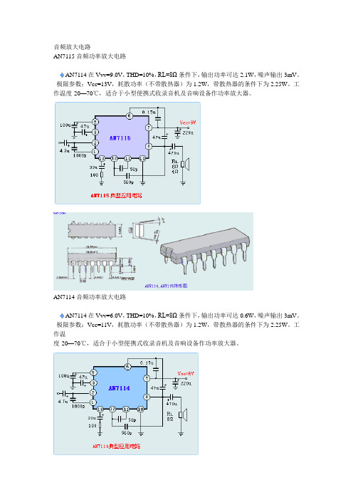
音频放大电路AN7115 音频功率放大电路AN7114在Vvv=9.0V,THD=10%,RL=8Ω条件下,输出功率可达2.1W,噪声输出3mV。
极限参数:Vcc=13V,耗散功率(不带散热器)为1.2W,带散热器的条件下为2.25W。
工作温度-20—70℃,适合于小型便携式收录音机及音响设备作功率放大器。
AN7114 音频功率放大电路AN7114在Vvv=6.0V,THD=10%,RL=8Ω条件下,输出功率可达0.6W,噪声输出3mV。
极限参数:Vcc=11V,耗散功率(不带散热器)为1.2W,带散热器的条件下为2.25W。
工作温度-20—70℃,适合于小型便携式收录音机及音响设备作功率放大器。
BA313 带ALC录放音电路BA313是一个内置自动电平控制电路(ALC)的录放音前置放大电路,常用于盒式磁带录音机,9脚DIP双列直插封装,电路具有如下特点:自动电平控制范围宽,工作电压范围宽(3—12V),高增益,低失真,低噪声。
BA328 立体声前置放大电路BA328具有双路前置放大电路,它具有外接元件少,安装方便等特点,单8脚直插封装。
电路特点如下:工作电压范围宽,噪声小,开环增益高,左右声道平衡性好。
常用于磁带录放音机,汽车立体声收音机及家用音响设备。
BA328极限参数如下:最高电源电压18V,最大功耗:540mW,工作温度:-25-70℃。
BA532 音频功率放大电路BA532与用于OTL电路的低频功率放大电路,输出功率高达5.8W,内设负载短路、过电压和过热保护电路,单列10 脚封装,电路特点有:在电源电压为13.8V时,8Ω负载阻抗,THD=10%时,输出功率可达5.8W,纹波抑制比高达40dB,引脚与BA511A、BA521相同。
常用于汽车立体声收录音机,收音机、电视机和磁带录音机中作功率输出电路。
BA536 4.5W双声道功率放大电路BA536是一个双声道音频功率放大电路,它具有通道平衡好、增益差小,12脚DIP单列直插封装,电路具有如下特点:输出功率每声道4.5W(4Ω负载阻抗,12V电源电压时),5.5W(3Ω负载阻抗,12V电源电压时)。
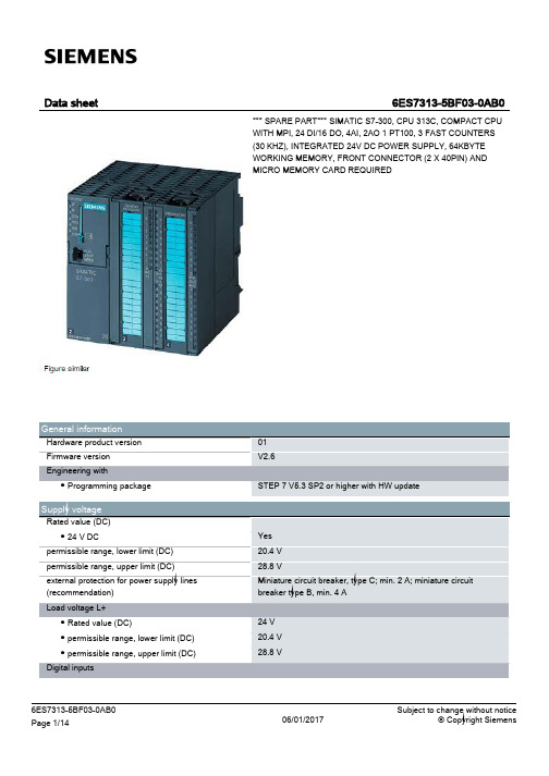
SIMATIC S7-300 CPU 313C 产品说明书
128 byte 128 byte
124.0 to 126.7 124.0 to 125.7 752 to 761 752 to 755
1 016 1 016 1 008 1 008
253 253 250 250
3
none 4
8 8 6
4 8; In rack 3 max. 7
Yes Yes 6 wk; At 40 °C ambient temperature 10 s
IEC timer ● present ● Type ● Number
Data areas and their retentivity retentive data area in total Flag ● Number, max. ● Retentivity available ● Retentivity preset ● Number of clock memories Data blocks ● Number, max. ● Size, max. ● Retentivity adjustable ● Retentivity preset Local data ● per priority class, max.
Hardware configuration Number of expansion units, max. Number of DP masters ● integrated ● via CP Number of operable FMs and CPs (recommended) ● FM ● CP, PtP ● CP, LAN Rack ● Racks, max. ● Modules per rack, max.
Nesting depth ● per priority class ● additional within an error OB
MAX313中文资料

Note 1: Signals on NC_, NO_, COM_, or IN_ exceeding V+ or V- will be clamped by internal diodes. Limit forward diode current to maximum current rating.
元器件交易网
MAX312/MAX313/MAX314
10Ω, Quad, SPST, CMOS Analog Switches
ABSOLUTE MAXIMUM RATINGS
Voltages Referenced to GND V+ ...........................................................................-0.3V to +44V V- ............................................................................+0.3V to -44V V+ to V-...................................................................-0.3V to +44V VL .....................................................(GND - 0.3V) to (V+ + 0.3V) All Other Pins (Note 1) ................................(V- - 2V) to (V+ + 2V)
Range (2Ω max) o Guaranteed ESD Protection > 2000V per Method
KAPPA LBP压缩器数据表说明书
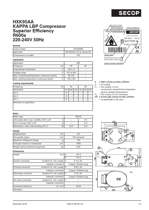
December 2016 DES.D.564.R1.02 1/2HXK95AAKAPPA LBP Compressor Superior Efficiency R600a220-240V 50HzGeneral Code number CDO00085ApprovalsEN 60335-2-34 w. Annex AACompressors on pallet 100Application Application LBPFrequencyHz 5060Evaporating temperature °C -35 to -5–Voltage rangeV 187 to 264–Max. condensing temperature continuous (short)°C 60 (70)–Max. winding temperature continuous (short)°C130 (130)–Cooling requirements Frequency Hz5060Application LBP MBP HBP LBP MBP HBP32°C S –––––38°C S –––––43°CS–––––Remarks on application:Motor Motor typeRSCRLRA (rated after 4 sec. UL984), HST | LST A – 3.8Cut in Current, HST | LSTA –11.6Resistance, main | start winding (25°C)Ω22,415,3Design Displacement cm 39.6Oil quantity (type)cm 3165 (mineral)Maximum refrigerant charge g 150Free gas volume in compressor cm 31560Weight without electrical equipment kg8.60Dimensions Heightmm A167.0B173.5Suction connector location/I.D. mm | angle C6.15 | 35°material | comment Copper | Rubber plugProcess connector location/O.D. mm | angle D6.00 | 35°material | comment Copper | Rubber plugDischarge connector location/I.D. mm | angle E5.15 | 40°material | comment Copper | Rubber plugOil cooler connector location/I.D. mm | angle F–material | comment–Connector tolerance I.D. mm±0.05Remarks:S = Static cooling normally sufficient O = Oil coolingF 1 = Fan cooling 1.5 m/s(compressor compartment temperature equal to ambient temperature)F 2 = Fan cooling 3.0 m/s necessarySG = Suction gas cooling normally sufficent –= not applicable in this area2/2 DES.D.564.R1.02 December 2016Secop accepts no responsibility for possible errors in catalogs, brochures, and other printed material. Secop reserves the right to alter its products without notice. This also applies to products already on order provided that such alterations can be made without subsequential changes being necessary to specifications already agreed. All trademarks in this material are the property of the respective companies. Secop and the Secop logotype are trademarks of Secop GmbH. All rights reserved.Accessories for HXK95AA Code numberTest conditions EN 12900Household ASHRAE LBP Run capacitor (compulsory)4.8 mm or 6.3 mm spade connectors 4 μF Condensing temperature 55°C 54.4°C Terminal board4.8 mm spade connectorsZX F5Ambient temperature 32°C 32.2°C (incl. ePTC and external protector)Suction gas temperature 32°C 32.2°C Terminal board6.3 mm spade connectors DA F5Liquid temperatureno subcooling32.2°C(incl. PTC and external protector) 4.8 mm spade connectorsZA F5Motor ProtectorAE18 FU xF5Cable clamp (screws not included)113410_Cover157595_Evaporation tray (optional)113188_All-in-one equipment , e.g. 4ZNCode number Mounting accessories Code numberCover / cable clamp + screws / earthing screw16168000on request, various options available。
SDC-313系列SDC-243系列
SDC-313系列SDC-243系列彩色CCD摄像机使用说明书说明在安装和使用摄像机之前,请仔细阅读说明书。
P/No. : 6806-0444-01A制造商:天津三星光电子有限公司地址:天津市南开区平昌道7号电传邮编:300190网址:感谢您购买三星CCD摄像机,在使用摄像机前,请确认摄像机制式和正确的输入电压,为了让您完全的了解本说明,我们将介绍一些我们的产品。
■SDC-313系列(410,000 像素)•NTSC 制式•PAL 制式SDC - 313ND SDC - 313PD SDC - 313NASDC - 313PA■SDC-243系列(270,000 像素)•NTSC 制式•PAL 制式SDC - 243ND SDC - 243PD SDC - 243NASDC - 243PA■型号划分SDC - 313 x xSDC - 243 x x•信号系统N NTSC 制式P PAL 制式•电源D DC 12V A AC 24V~本设备应该由具有专业资格的人员进行安装,并应在允许地区范围内安装。
说明-此设备是根据FCC条约第15项的CLASS A数码设备限制测试的。
这些限制是为了防止产品在商贸环境中使用时的有害干扰而提供保护设计的。
本产品生产和使用时可以放射出电磁波,如果您未按照说明书安装使用,可能会产生有害的电磁干扰。
当在居民区里使用本产品时,有可能会产生有害的电磁干扰,在这种情况下,使用者需要自费改善此种干扰。
注意-在未经生产商允许的情况下,私自更换或修理摄像机,会使消费者的权益无法保障。
警告:为防止电击或火灾的危险:◆不要使用其它未经指定的电源。
◆不要将制品暴露在雨中或潮湿的环境中。
警告-为了防止有火灾和电击的危险,请不要将本产品放置在雨中或者潮湿的环境中。
特征目录卓越的逆光补偿逆光补偿技术允许摄像机在任何环境下,找到最佳摄像条件且自动给出所需的光量补偿。
因此您总可以得到清晰的精美的细节以及完美的光线对比度。
产品详细介绍-武汉市亨利贞科技有限公司
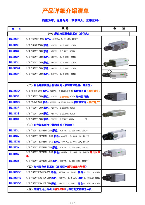
产品详细介绍清单质量为本,服务为先,诚信做人,互惠互利。
型号规格备注(一)彩色枪型摄像机系列(分体式)HL-313H1/4“SHARP CCD彩色,420TVL,1。
0 LUX,DC12VHL-313I1/3“SHARPCCD彩色,420TVL,1。
0 LUX,DC12VHL-313J1/4“SONY CCD彩色,420TVL,0.5 LUX,DC12VHL-313K 1/3“SONY CCD彩色,420TVL,0。
5 LUX,DC12VHL-313L 1/3“SONY CCD彩色,460TVL,0。
5 LUX,DC12VHL-313M 1/3“SONY CCD彩色,480TVL,0。
5 LUX,DC12VHL-313N 1/3“SONY CCD彩色,540TVL,0。
5 LUX,DC12V(二)彩色超低照度分体积系列(彩转黑可选型/ 黑白型)HL-313O1/3“SONY CCD彩色,420TVL,0.05LUX,DC12V彩转黑可选(感红外灯)HL-313P1/3“SONY CCD彩色,420TVL,0.001LUX,DC12V彩转黑可选HL-313Q1/3“SONY CCD彩色,460TVL,0.05LUX,DC12V彩转黑可选(感红外灯)HL-313R1/3“SONY CCD彩色,420TVL,0.003LUX,DC12VHL-313S1/3“SONY CCD彩色,480TVL,0.003LUX,DC12VHL-313T1/3“SONY CCD彩色,530TVL,0.03LUX,DC12V 无(三)彩色超低照度分体积系列(高端型)HL-313U 1/3“SONY EXVIEW CCD彩色,420TVL,0。
008 LUX,DC12VHL-313V 1/3“SONY EXVIEW CCD彩色,460TVL,0。
005 LUX,DC12VHL-313W 1/3“SONY EXVIEW CCD彩色,480TVL,0。
CPU313-2DP技术参数
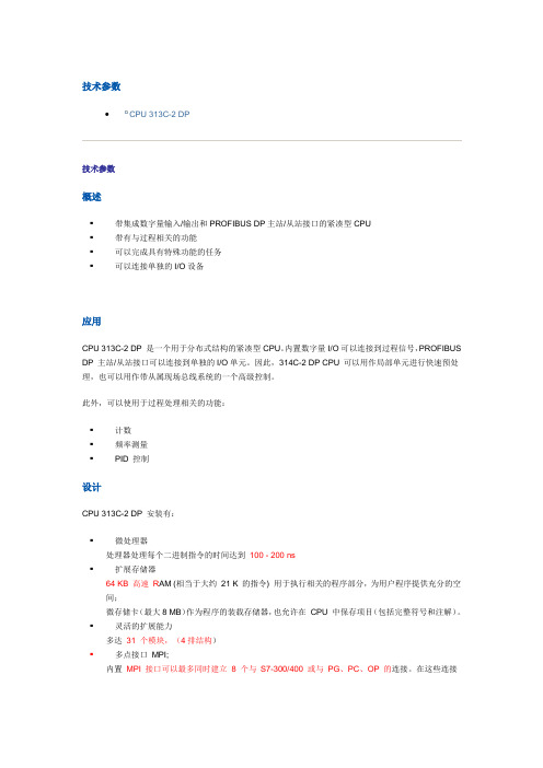
技术参数CPU 313C-2 DP技术参数概述▪带集成数字量输入/输出和PROFIBUS DP主站/从站接口的紧凑型CPU▪带有与过程相关的功能▪可以完成具有特殊功能的任务▪可以连接单独的I/O设备应用CPU 313C-2 DP 是一个用于分布式结构的紧凑型CPU。
内置数字量I/O可以连接到过程信号,PROFIBUS DP 主站/从站接口可以连接到单独的I/O单元。
因此,314C-2 DP CPU 可以用作局部单元进行快速预处理,也可以用作带从属现场总线系统的一个高级控制。
此外,可以使用于过程处理相关的功能:▪计数▪频率测量▪PID 控制设计CPU 313C-2 DP 安装有:▪微处理器处理器处理每个二进制指令的时间达到100 - 200 ns▪扩展存储器64 KB 高速R AM (相当于大约21 K 的指令) 用于执行相关的程序部分,为用户程序提供充分的空间;微存储卡(最大8 MB)作为程序的装载存储器,也允许在CPU 中保存项目(包括完整符号和注解)。
▪灵活的扩展能力多达31 个模块,(4排结构)▪多点接口MPI;内置MPI 接口可以最多同时建立8 个与S7-300/400 或与PG、PC、OP 的连接。
在这些连接中,始终分别为PG 和OP 各保留一个连接。
通过“全局数据通讯”,MPI可以用来建立最多16个CPU组成的简单网络。
▪PROFIBUS DP 接口:带有PROFIBUS DP 主/从接口的CPU 313C-2 DP 可以用来建立高速、易用的分布式自动化系统。
对用户来说,分布式I/O单元可作为一个集中式单元来处理(相同的组态、编址和编程).▪内置输入/输出16个数字量输入(均可用于报警处理)和16个数字量输出。
功能▪口令保护用户程序使用密码保护,可防止非法访问。
▪诊断缓冲;最后100个故障和中断事件保存在该缓冲区中,供诊断使用。
▪免维护的数据后备;在断电的情况下,CPU自动地将保持数据写到微存储卡中,这样,在再次通电时它能保持不变。
313D 315D 海猫挖掘机零部件参考指南说明书

313D, 313D2 & 315D HYDRAULIC EXCAVATORS PARTS REFERENCE GUIDESCHEDULED MAINTENANCE PARTSThis guide is designed to provide you with a quick reference for the parts and part numbers you need to keep your Cat 313D/315D Hydraulic Excavator running at peak efficiency.MAINTENANCEProactive preventative maintenance extends the life of your machine and protects your investment. Only Caterpillar knows Cat equipment’s filtration and lubrication requirements and offers parts kits to match your machine’s maintenance cycles.REPLACEMENT PARTSProper maintenance minimizes the need for repair and replacement. In the event that replacement parts are required, the use of genuine Cat parts helps maximize machine performance and maintains high resale value.Thank you for selecting the Cat ® 313D/315D Hydraulic Excavator.PROTECT YOUR INVESTMENT WITH GENUINE CAT ®PARTSWEAR PARTSREPAIR PARTSPLANNED MAINTENANCE KITSUNDERCARRIAGECAB GLASSGET BUCKET TEETHHOODS/DOORS/CAPSACCESSORIES/MIRRORS/LIGHTSENGINE PARTS*Reman PartsCYLINDER PARTSCYLINDER PARTSKITS*Reman PartKits are not available through . Please contact your local Cat Dealer.EXCAVATOR LINKAGE CONFIGURATIONSeparate Configurations - Reach, Long ReachTo buy Cat parts online, visit if you have a dealer account or (US only) if you don’t yet have an account.Cat Filters Provide Longer Injector LifeChances are, you don’t skip oil changes or regular maintenance on the family car. So why skip planned maintenance on your Cat equipment? Cat fuel filters outperform the competition, with up to 45% longer injector life and up to 80% decreased cost per hour.*Productivity & Hydraulics Go Hand In HandIf your hydraulic system isn’t performing at peak efficiency, it’s robbing your machine of performance. Efficiency losses usually occur slowly and can reach 20% before you detect a problem — that’s one day of lost production every week! These losses can also increase your fuel consumption and operating costs.Need help?Your local Cat dealer can provide:• Technical Support • Parts needed and equipment fit • Customer Value Agreements • Repair financing • Oil sample analysis • Rental Services Find your local dealer at today.* Visit https:///filtersandfluids for more details AEHJ0209© 2020 Caterpillar. All Rights Reserved. CAT, CATERPILLAR, LET’S DO THE WORK, their respective logos, “Caterpillar Corporate Corporate Yellow”, the “Power Edge” and Cat “Modern Hex” trade dress as well as corporate and product identity used herein, are trademarks of Caterpillar and may not beused without permission.。
XP313I使用手册
3 技术指标
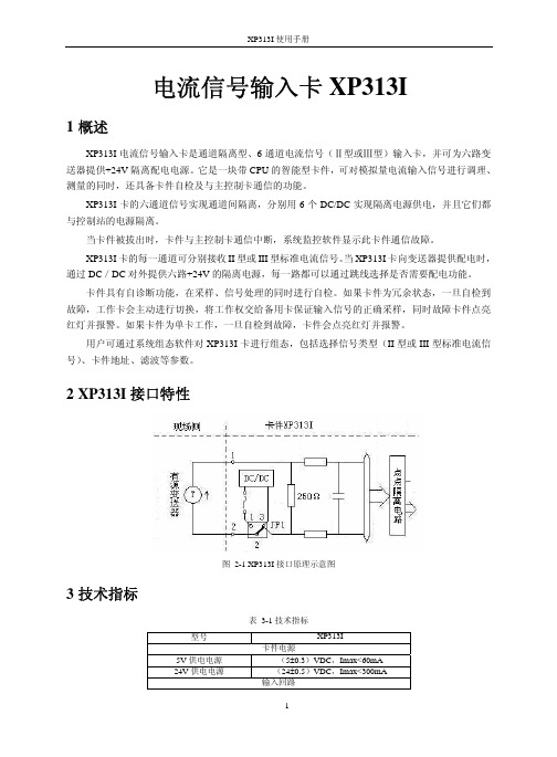
图 2-1 XP313I 接口原理示意图
型号
5V 供电电源 24V 供电电源
表 3-1 技术指标
XP313I 卡件电源
(5±0.3)VDC,Imax<60mA (24±0.5)VDC,Imax<300mA 输入回路
1
XP313I 使用手册
通道数 信号类型 滤波时间 分辨率 输入阻抗 隔离方式 隔离电压
常亮 闪
FAIL(红) RUN(绿) WORK(绿) COM(绿)
故障指示 运行指示 工作/备用
通信指示
正常 自检故障 CPU 复位
不运行
-正常
备用 工作 切换中
无通信 组态错误
正常
POWER(绿) 5V 电源指示 故障 正常 --
4.3 端子定义及接线
端子接线方法如下表所示。表中 CHX+表示第 X 通道正端,CHX-表示第 X 通道负端,如第 1 通道的正、负端为:CH1+、CH1-。NC 表示该端子不接线。
6 资料版本说明
资料版本号 XP313I 使用手册(V1.0)
表 6-1 版本升级更改一览表 输出时间
更改说明
4
XP313I 卡的六通道信号实现通道间隔离,分别用 6 个 DC/DC 实现隔离电源供电,并且它们都 与控制站的电源隔离。
当卡件被拔出时,卡件与主控制卡通信中断,系统监控软件显示此卡件通信故障。 XP313I 卡的每一通道可分别接收 II 型或 III 型标准电流信号。当 XP313I 卡向变送器提供配电时, 通过 DC/DC 对外提供六路+24V 的隔离电源,每一路都可以通过跳线选择是否需要配电功能。 卡件具有自诊断功能,在采样、信号处理的同时进行自检。如果卡件为冗余状态,一旦自检到 故障,工作卡会主动进行切换,将工作权交给备用卡保证输入信号的正确采样,同时故障卡件点亮 红灯并报警。如果卡件为单卡工作,一旦自检到故障,卡件会点亮红灯并报警。 用户可通过系统组态软件对 XP313I 卡进行组态,包括选择信号类型(II 型或 III 型标准电流信 号)、卡件地址、滤波等参数。
- 1、下载文档前请自行甄别文档内容的完整性,平台不提供额外的编辑、内容补充、找答案等附加服务。
- 2、"仅部分预览"的文档,不可在线预览部分如存在完整性等问题,可反馈申请退款(可完整预览的文档不适用该条件!)。
- 3、如文档侵犯您的权益,请联系客服反馈,我们会尽快为您处理(人工客服工作时间:9:00-18:30)。
PRESSURE RANGES:
• From 0-3 through 0-100 psig (See ordering guide.)
ACCURACY:
• From ±0.1% FSO (RSS) to ±0.5% FSO (RSS) (See specifications & ordering guide.)
TOPE Co., Ltd. Tel. (02) 8228-0658 • Fax. (02) 8228-0659 • E-mail: tope@ • Website: SL5B-313L.02C
元器件交易网
SPECIFICATIONS
Specifications printed on reverse side of this brochure. GP:50 reserves the right to make product improvements and amendments to the product specification stated throughout this brochure without prior notification. Please contact the factory on all critical dimensions and specifications for verification.
•
MODEL 313L 4-20mA SERIES B ±0.5% FSO (RSS) C ±0.2% FSO (RSS) D ±0.1% FSO (RSS)
•
•
•/•/•
OPTIONS AA None (standard connector) CZ Alternate cable length (specify) ALTERNATE PRESSURE PORT FH 1/8” NPT (F) FL 1/8” NPT (M) LD Tapered inlet LJ Tapered inlet with standoff plate
SPECIFICATIONS
Unless otherwise stated, these specifications are the standards to which the units are normally constructed. Alterations may be easily and readily accomplished by the standard modification code or by discussion with the factory. We invite your inquiry. Accuracy (Static error band includes non-linearity, hysteresis, non-repeatability) Series B ±0.5% FSO (RSS) Series C ±0.2% FSO (RSS) Series D ±0.1% FSO (RSS) Temperature Limits* Compensated Operating Storage Temperature Compensation* Zero Span Electricals Excitation Zero Balance Span Load Impedance Circuit Protection Insulation Resistance Resolution Mechanicals Proof Pressure Burst Pressure External Pressure Case Materials Pressure Response Long Term Stability Position Effect Calibration Orientation Cycle Life Fluid Fill Length Diameter Connections Pressure Electrical Cable Identification * See modifications on ordering guide. 0°F to +140°F -40°F to +150°F -40°F to +150°F Less than ±2% FSO/100°F at full scale pressure range and/or upper range limit Less than ±2% FSO/100°F at full scale pressure range and/or upper range limit 12 - 40 Vdc 4.0mA ±2% FSO at 70°F 16.0mA ±2% FSO at 70°F 1400 ohm maximum at 40 Vdc excitation Short Circuit - Indefinite Reverse Wired - Indefinite Greater than 10 M ohm at 50 Vdc and 70°F Infinite 2 times rated full scale pressure 4 times rated full scale pressure 500 psi maximum Type 316 stainless steel < 5 ms to 90% < +0.5% FSO / year ±0.01% FSO for a 90° change in orientation Horizontal unless specified 1 million pressure cycles 200 CS. Dow Corning 200. (Silicon Oil) 6.1 inches 1.0 inches PVC bullet nose Molded polyurethane jacket, 6 conductor with breather tube, 24 AWG, 8’ long Etched onto housing
元器件交易网
SUBMERSIBLE LEVEL TRANSMITTER
Model 313L
GENERAL PURPOSE
FEATURES:
• • • • All-welded, stainless steel construction Rugged, all encapsulated electronics. Leakproof 1/2” NPT conduit thread standard
FLATS
1/2 NPT CONDUIT FITTING
1.0" DIA. REF.
BREATHER TUBE
1.00" 6.1 REF.
SUBMERSIBLE CABLE
2770 Long Road, Grand Island, NY 14072 USA Tel. (716) 773-9300 • Fax (716) 773-5019 • E-mail: sales@ • Website:
WIRING CODE
313L Red Green White Black Blue Brown Shield + Excit./Signal NC NC - Excit./Signal NC Option GH NC Option GH Open
Some options will affect dimensions. Consult factory if important. Note: Altering option codes will alter the unit length.
with Option LJ tapered inlet with stand off plate
ORDERING GUIDE
Ordering: Specify model, and pressure range and indicate modifications or accessories required. Use the following codes to identify desired item. Example 313L-B-PZ-LJ MODEL SERIES RANGE OPTIONS
PRESSURE RANGE psi in wc PG 3 XK 100 PJ 5 XM 150 PL 7.5 XO 200 PN 10 XQ 300 PP 15 PR 20 PO 25 PT 30 PV 50 PX 75 PZ 100
GENERAL CT Tefzel jacketed cable GA Standardized output to ±0.5% FSO GB Alternate output, pressure units, or full scale outputs that are non-standard GE Improved temperature compensation to ±0.5% FSO unless otherwise specified GG Alternate calibration signal GH Internal calibration resistor set to 100 ±0.5% FSO unless other wise specified JH Remote cable mounted (in-line) zero & span controls. 3’ cable on open side. Length of cable on closed side as required. (500’ maximum) GZ Customer special
