整机验证服务 HCT-201003-RoHS zjyz
2010年第一季度检测合格安全产品名单发布

防火墙
防火 墙
D L- 6 0 F 10
DF 一 5 0 L 20 V 61 V AS V12 S - . V3O .
友讯电予设备 (k ) -海 有限公 司
友讯电子设备 ( j海)有限公司
小 型l火墙 防
小型防火墙
XKC 1 8 2 1 0 1 M e e u n rt l yMa a e 3 3 8 02 32 AfeV le af i n g r i t
XKC 5 1 2 2 l 9 S ma te B ih ma l twa 3 8 9 01 0 2 y ne r t iGae y g
86 30
I B-NPS 3000
赛门铁 克软件 ( 北 ) 有限公司
江 苏意源科 技有限公 司
反垃圾m件 ( 基本级 )
信达环宇漏洞扫描 系统
V1 . 6
XDH Y N SV80 — S .
深圳市赛虢科 技有限公司
北京信达 环宇安全网络技术有 限公司
其它‘ 企业标准 )
网络脆弱性 扫描 ( 基本 级 )
10 1 0 00
1O l 0 O1
X C0 7 0232 Q K 7 2 0 2 10 1 Q令牌 动态密码议证 系统
X C 0 6 0 2 19 K 7 26 2102
X C 5 2 2 10 1 K 386 02 22 X C 52 02 22 K 3 8 5 2 1 0 1
中信联 电子签章系统
Gel ra 网络入 侵防御系统 电脑家长
V1 . O Gna I SV l tP _ 0 V30 .
D - 0 FL 21
DFL一800
发讯电子设备 ( 上海 ) 有限公司
Gap Checker ISA3-#L 安装说明书
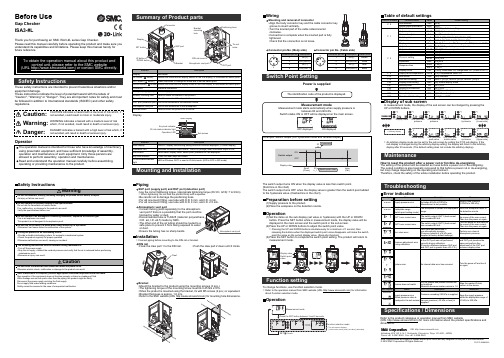
Before UseGap CheckerISA3-#LSafety InstructionsPipingSUP port (supply port) and OUT port (detection port)•Use the correct tightening torque. (Appropriate tightening torque (Rc1/8 • G1/8): 7 to 9 Nm)∗: When tightening, do not hold the product body with a spanner.•Be careful not to damage the positioning boss.•For ø6 one-touch fitting, use tube with O.D. 6 mm, and I.D. 4 mm.•For ø4 one-touch fitting, use tube with O.D. 4 mm, and I.D. 2.5 mm.Safety InstructionsMounting and InstallationThank you for purchasing an SMC ISA3-#L series Gap Checker.Please read this manual carefully before operating the product and make sure you understand its capabilities and limitations. Please keep this manual handy for future reference.These safety instructions are intended to prevent hazardous situations and/or equipment damage.These instructions indicate the level of potential hazard with the labels of"Caution", "Warning" or "Danger". They are all important notes for safety and must be followed in addition to International standards (ISO/IEC) and other safety regulations.Atmospheric vent portblocked by water or dust.O.D. ø4, I.D. ø2.5) made by SMC.or dust.•Ensure the tubing has no sharp bends.OperatorTie rod holesBracket holeBracket•Mount the bracket to the product using the mounting screws (3 pcs.).•The tightening torque of the mounting screw must be 0.45 Nm ±10%.•When the product is mounted using the bracket, fix with M5 screws (2 pcs.) or equivalent.•Bracket thickness is approx. 1.6 mm.•Refer to the SMC website (URL ) for mounting hole dimensions.Switch point valueFunction selection mode∗: The sub screen displays[ the function name ] and [ set value ] alternately.The switch output turns ON when the display value is less than switch point.(Solid line in the chart)The switch output turns OFF when the display value is greater than the switch point added to the hysteresis value. (Dashed line in the chart)To change functions, use Function selection mode.∗: Refer to the operation manual from SMC website (URL ) for information about Function selection mode.Installation∗: Connect piping before mounting to the DIN rail or bracket.DIN rail•Hook the claw part 1 to the DIN rail. •Push the claw part 2 down until it clicks.WiringMounting and removal of connector•Align the body connector key and the cable connector key groove to insert vertically.•Turn the knurled part of the cable sideconnector clockwise.•Connection is complete when the knurled part is fully tightened.Check that the connection is not loose.Switch Point SettingOperation(1)Set the items on the sub display (set value or hysteresis) with the UP or DOWN button. Press the SET button while in measurement mode, the display value will be displayed in the main screen and the switch point in the sub screen.(2)Press the UP or DOWN buttons to adjust the switch point value.∗: Pressing the UP and DOWN buttons simultaneously for a minimum of 1 second, thenreleasing the buttons when the displayed switch point value disappears, will make the switch point the same as the current display value. (Snap shot function)(3)Press the SET button to complete the switch point setting. The product will return to measurement mode.Function settingOperationDisplay of sub screenIn measurement mode, the display of the sub screen can be changed by pressing the ∗: Arbitrary displaypeak value hysteresis bottom value (Upper side)MaintenanceHow to reset the product after a power cut or forcible de-energizingThe setting of the product will be retained as it was before a power cut or de-energizing.The output condition is also basically recovered to that before a power cut or de-energizing,but may change depending on the operating environment.Therefore, check the safety of the whole installation before operating the product.Specifications / DimensionsRefer to the product catalogue or operation manual from SMC website(URL ) for more information about the product specifications and dimensions.Akihabara UDX 15F , 4-14-1, Sotokanda, Chiyoda-ku, Tokyo 101-0021, JAPAN Phone: +81 3-5207-8249 Fax: +81 3-5298-5362URL TroubleshootingConnector pin No. (Body side)Connector pin No. (Cable side)Power is suppliedPreparation before setting(1)Supply pressure to the product.(2)Place the workpiece on the detection nozzle.Note: Specifications are subject to change without prior notice and any obligation on the part of the manufacturer.© 2018 SMC Corporation All Rights Reserved Display∗: An arbitrary display mode can be set for the sub screen by setting the [F10] sub display. If the sub display is changed during the arbitrary display setting, the display will return to the arbitrary display after 30 seconds. (The default setting does not include the arbitrary display).PS ※※-OMW0010。
环氧乙烷灭菌器验证方案
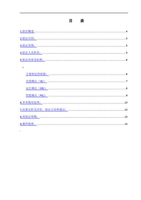
目录1.验证概述: (4)2.验证目的: (5)3.验证范围: (5)4.验证人员职责: (5)5.验证内容及标准: (6)…方案制定的依据: (6)安装确认(IQ): (7)运行确认(OQ): (8)性能确认(PQ): (9)6.异常情况处理: (13)7.结果分析及评价、验证小结和建议: (13)8.再验证周期: (13)9.最终批准: (13))1.验证概述:简介:科技有限公司位于沈阳经济技术开发区,新建医疗器械生产车间,公司特选用杭州申生消毒设备有限公司的申生牌HSX型环氧乙烷灭菌器(型号HSX-3)。
为确认新设备在新建车间满足安装、运行、性能及生产工艺要求,特此制订本验证方案,对设备进行验证。
该设备用于医用防护口罩的灭菌。
为了确认该设备在规定的条件下满足器具灭菌质量,因此对HSX-3型环氧乙烷灭菌器进行验证。
设备基本情况:设备名称:环氧乙烷灭菌器型号:HSX-3生产厂家:杭州申生消毒设备有限公司)设置场所:灭菌车间)。
设备结构:该设备由灭菌室、真空系统、热循环系统、加药系统、门及密封系统、残气处理系统、电气控制系统及计算机监控和管理系统组成。
柜体采用双层结构,内柜采用防腐蚀不锈钢经喷砂、钝化处理;外层用钢板。
灭菌采用了脉动真空的排气方式,使空气排除量达99%以上,完全排除温度“死角”与小装置效应,保证了灭菌质量。
工作原理及模式描述:环氧乙烷的灭菌机理是:EO能与细菌蛋白质上的羧基(-COOH)、氨基(-NH2 )、巯基(-SH)和羟基(-OH)发生烷基化反应使蛋白质失去在基本代谢中需要的反应基,阻碍了细菌蛋白质正常的化学反应和新陈代谢而导致微生物死亡。
#2.验证目的:通过对HSX-3型环氧乙烷灭菌器的预确认、安装确认、运行确认、性能确认的验证,证明HSX-3型环氧乙烷灭菌器的制造、性能符合生产要求及GMP要求。
通过灭菌过程确认(灭菌器、工艺参数、操作等)确保灭菌系统和灭菌过程能持续稳定的生产无菌的产品,无菌保证水平为10-6(ISO 11135-1:2007,),而且灭菌后产品和包装的性能符合预定的要求。
“红兔子”系统验证作业指导书
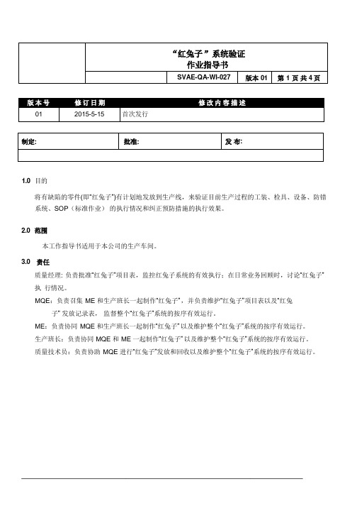
1.0 目的将有缺陷的零件(即“红兔子”)有计划地发放到生产线,来验证目前生产过程的工装、检具、设备、防错系统、SOP(标准作业)的执行情况和纠正预防措施的执行效果。
2.0 范围本工作指导书适用于本公司的生产车间。
3.0 责任质量经理: 负责批准“红兔子”项目表,监控红兔子系统的有效执行;在日常业务回顾时,讨论“红兔子”执行情况。
MQE:负责召集ME 和生产班长一起制作“红兔子”,并负责维护“红兔子”项目表以及“红兔子”发放记录表,监督整个“红兔子”系统的按序有效运行。
ME:负责协同MQE 和生产班长一起制作“红兔子”以及维护整个“红兔子”系统的按序有效运行。
生产班长:负责协同MQE 和ME 一起制作“红兔子”以及维护整个“红兔子”系统的按序有效运行。
质量技术员:负责协助MQE 进行“红兔子”发放和回收以及维护整个“红兔子”系统的按序有效运行。
4.0 程序4.1“红兔子”选取原则4.1.1 客户及内部曾发生过的优先级问题;4.1.2 有错漏装风险的工序或零件;4.1.3 测试设备或防错工位的验证。
4.2“红兔子”项目表4.2.1 根据“红兔子”选取原则,现场质量组织SDT(质量、生产、工艺)成员共同选择“红兔子”项目,完成“红兔子”制作,制定“红兔子”项目表并经质量经理批准。
4.2.2 根据”红兔子”的实施结果和内外部问题的发生情况对”红兔子”项目进行实时调整。
4.3“红兔子”制作要求4.3.1“红兔子”样件外观上与正常供货零件无差异(除外观缺陷“红兔子”);4.3.2“红兔子”的缺陷必须是明确的,不存在疑义的(即时有时无的缺陷,不能制作成“红兔子”);4.3.3 涉及到安全特性的项目,原则上不得制作“红兔子”。
4.4“红兔子“保存要求4.4.1.针对总装线,“红兔子”要进行定置定位管理,放置在规定区域,由MQE 负责保管。
“红兔子”放置区域要列出红兔子项目表。
4.4.2 针对SMD 产线, “红兔子”保存不作具体要求,由MQE 视实际情况确定需不需要保存。
正泰集团C安全认证证书一览表
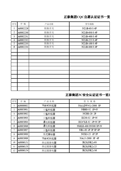
DZ20Y ,J-630 3P 4P DZ20Y ,J-400 3P 4P
DZ20C-400 3P NM1-63S. H 3P 4P
DZ5-50 3P DZ5-20 3P NRE8-40 DZ20C-250 3P DZ20Y.J.G-225/3P DZ20J-225/4P
正泰集团3C安全认证证书一览表 第6页 型号规格 DZ20C-160 3P DZ20Y. J.G-100/3P DZ20J-100/4P DW15-4000 DW15-2500 HD11-600 3P HD11-200 3P NRC8-40.31.22 HD11-400 RT14-32 RT14-20 RT14-63 HDLRS-200 HDLRS-150 HDLRS-100 HDLRT0-600 HDLRT0-400
正泰集团3C安全认证证书一览表 第7页 型号规格 HDLRT0-200 HDLRT0-100 RT28-63 RT28-32
99 A0009444 100 A0009445 101 A0009446 102 A0009447 103 A0009448 104 A0009449 105 A0009450 106 A0009451 107 A0009452 108 A0009453 109 A0009454 110 A0009455
70 A0009414 71 A0009415 72 A0009416 73 A0009416 74 A0009418 75 A0009419 76 A0009420 77 A0009421 78 A0009422
序号 序 编
79 A0009423 80 A0009424 81 A0009425 82 A0009426 83 A0009427 84 A0009427 85 A0009429 86 A0009430 87 A0009432 88 A0009433 89 A0009434 90 A0009435 91 A0009436 92 A0009437 93 A0009438 94 A0009439
med-certificate-for-novec-1230-ecs-500-psi说明书

Form code: MED 201.NOR Revision: 2021-03 Page 1 of 3Certificate No: MEDB00005BK Revision No: 1Application of: Directive 2014/90/EU of 23 July 2014 on marine equipment (MED), issued as "Forskrift om Skipsutstyr" by the Norwegian Maritime Authority. This Certificate is issued by DNV AS under the authority of the Government of Norway.This is to certify:That the Equivalent fixed gas fire extinguishing systems components (extinguishing medium, head valves and nozzles) for machinery spaces and cargo pump roomswith type designation(s) Novec 1230 ECS 500 psiIssued toKidde-Fenwal, Inc.Ashland, MA , USAis found to comply with the requirements in the following Regulations/Standards:Further details of the equipment and conditions for certification are given overleaf.This Certificate is valid until 2025-09-10.Issued at Høvik on 2021-06-17DNV local station:Certification & Inspection ServicesApproval Engineer: Helge BjørnaråNotified Body No.: 0575for DNV ASSverre Olav Bergli Head of Notified BodyThe mark of conformity may only be affixed to the above type approved equipment and a Manufacturer’s Declaration of Conformit y issued when the production-surveillance module (D, E or F) of Annex B of the MED is fully complied with and controlled by a written inspection agreement with a Notified Body. The product liability rests with the manufacturer or his representative in accordance with Directive 2014/90/EU.This certificate is valid for equipment, which is conform to the approved type. The manufacturer shall inform DNV AS of any changes to the approved equipment. This certificate remains valid unless suspended, withdrawn, recalled or cancelled.Should the specified regulations or standards be amended during the validity of this certificate, the product is to be re-approved before being placed on board a vessel to which the amended regulations or standards apply.LEGAL DISCLAIMER: Unless otherwise stated in the applicable contract with the holder of this document, or following from mandatory law, the liability of DNV AS, its parent companies and their subsidiaries as well as their officers, directors and employees (“DNV”) arising from or in connection with the services rendered for the purpose of the issuance of this document or reliance thereon, whether in contract or in tort (including negligence), shall be limited to direct losses and under any circumstance be limited to 300,000 USD.Digitally Signed By: Sæle-Nilsen, Dag Location: DNV Høvik, Norwayon behalf ofProduct description“Novec 1230 ECS 500 psi”,is a fixed gas fire extinguishing system using fire extinguishing agent Novec 1230 stored in steel cylinders as liquid and pressurized with nitrogen and distributed through pipes and nozzles.The extinguishing concentration and nozzles are covered by this type approval certificate. Documentation for the other system components shall be submitted and approved for each project.The system is to be designed in accordance with the “Principal Requirements” in IMO MSC/Circ.848 as amended by IMO MSC.1/Circ.1267.The extinguishing agent Novec 1230 is produced by 3M, Cordova, Illinois, USA.2) When calculated at 20°C. Ambient temperature to be determined case by case for each project3) NFPA 2001 (2008 Edition)The following associated companies are authorised by Kidde-Fenwal to apply this certificate:-Kidde-Fenwal Inc., Ashland, USA-Kidde Products Limited T/A Kidde Fire Production, Buckinghamshire, UKApplication/LimitationApproved for use as "total flooding" fire extinguishing system in machinery spaces and cargo pump rooms. The design gas concentration (diesel) shall be minimum 5.85% (applied on a net volume) and the maximum agent discharge time shall be 10 seconds for 95% of the extinguishing concentration. The extinguishing system shall be designed and installed according to SOLAS Ch. II-2, IMO MSC/Circ.848 as amended by IMO MSC.1/Circ.1267 and the maker’s manual.The following additional limitations will apply:A. Novec 1230 ECS 500 psi systems are not suita ble for the ship’s cargo holds. If Novec 1230 ECS 500 psi systemsare installed inside cargo pump rooms, all components shall be certified for use in hazardous areas, the design gas concentration shall be adjusted, and the system is subjected to case by case approval.B. If Novec 1230 agent is used above its NOAEL (calculated on net volume at max expected ambient temperature),means should be provided to limit exposure (IMO MSC.1/Circ.1267, 6). In no case should Novec 1230 be used in concentrations above its LOAEL.C. Steel storage cylinders of size 10 lb (4.5 kg) to 900 lb (408 kg). Cylinders being 81 L or larger is only acceptedwhen arrangements are provided on board to ensure that cylinders can be easily moved (even to shore) for service and recharging. All cylinders shall be of the same size.D. Cylinders are topped up with nitrogen to 34.5 bar (500 psi) at 21°C. The fill density shall be maximum 1.12 kg/L.Cylinders are to be delivered with product certificate or equivalent certificates acceptable to the flag administration and class.E. Cylinders are to be delivered with product certificate or equivalent certificates acceptable to the flag administrationand class.F. Cylinders to be located in a separate room in accordance with SOLAS Ch. II-2 Reg. 10.4.3 or distributed throughoutthe protected space in accordance with the requirements in IMO MSC/Circ.848 item 11 as amended by IMOMSC.1/Circ.1267. When distributed within the protected space, the min extinguishing concentration (after any single failure) shall be 4.5%.G. Components in the system will be regarded under pressure class II with a maximum design pressure of 40 bar (at54 °C). Consideration will though be made for piping and couplings inside the protected space.H. The nozzles are to be located in accordance with the Kidde manual. A basic rule is that one nozzle can as amaximum cover an area of 5 x 10 m. A 360° nozzles shall be located centrally in this area, the 180° nozzles on the sides (as applicable). The maximum cover height is 5 m. The minimum average nozzles pressure is 4.2 bar.I. Bilges (except open bilges in small volume engine rooms) are to be protected with a dedicated nozzle network.The following documentation is to be submitted to the flag administration in each case:a. Plans showing location of cylinders, piping, nozzles and release stations as well as the assembled systemb. Capacity calculations, including hydraulic flow calculations.c. Plans defining release lines and alarm system.d. Material specification and dimensions for piping and specifications for all other components.e. Ship specific release procedures and post discharge ventilation procedures.f. Manual containing design, inspection, operation and maintenance procedures.g. Control arrangements for closure of openings and stop of fans and any pressure relief devices as per IMOMSC/Circ.848, 13. These plans can also be supplied by yard.Testing at installations and periodical surveys-The system shall be tested as per maker’s manual, flag administration and class requirements.-The system is subject to biennial (every 2nd year) inspection by an approved service supplier. The attending surveyor will also apply requirement relevant for flag administration and/or class on newbuilding and ship inoperation surveys.Type Examination documentationDesign, Installation, Operation and Maintenance Manual No. 06-237589-001 dated May 2017 from Kidde Fire Systems. Addendum - 06-237784-001 (2” and 3” Valve Burst Disc Harmonization) issued August 2020 from Kidde Fire Systems. Addendum - 06-237595-003 (KFS, LLI,) issued June 2020 from Kidde Fire Systems.Addendum - 06-237595-004 (450 lb Cylinder) issued August 2020 from Kidde Fire Systems.Addendum - 06-237798-001 (2” El-check Valve) issued October 2020 from Kidde Fire Systems.Addendum - 06-237761-001 (3” Valve) issued January 2020 from Kidde Fire Systems.Addendum - 06-237766-001 (1 1/2” and 2” Flexible Discharge Hose) issued January 2020 from Kidde Fire Systems Addendum - 06-237775-001 (Manifold “Y” fitting) issued May 2020 from Kidde Fire Systems.Report No. HAI Project #5087 dated 28 June 2002, from Hughes Associates, Inc., Baltimore, USA.(tested on U.S. Coast Guard’s Fire & Safety Test Detachment in Mobile, AL).Report No. 04-CRADA-RDC-001, dated 16 November 2004, from Kidde-Fenwal Inc., Massachusetts, USA.(tested on U.S. Coast Guard’s Fire & Safety Test Detachment in Mobile, AL, witnessed by UL).Report File EX4674, Project 04NK23160 dated 1 February 2005 from UL, Northbrook, USA.Report No. 3026502 dated 24 March 2006,from FM Approvals, Norwood, USA.Report File EX4674, Project 4788267101 dated 30 March 2018 from UL, Northbrook, USA.Report File EX4674, Subscriber 359696001, Project 4789259964 dated 25 February 2020 from UL, Northbrook, USA. Report File EX4674_20141101 revised 24 November 2020 (2 pages) from UL, Northbrook, USAKidde-Fenwal component sheets, stamped July 2005.Tests carried outTested in accordance with IMO MSC/Circ.848 as amended by IMO MSC.1/Circ.1267.Marking of productMain components in the system are to be marked with name and address of manufacturer, type designation and MED Mark of Conformity (see first page).。
设备验证文件目录

PAZ2000I-C型智能检测自补颗粒机
VM-135-02
36
DPB-250E型自动泡罩包装机
VM-136-02
37
NJP-1200C型全自动胶囊填充机
VM-137-02
38
ZP-37型旋转式压片机
VM-138-02
设备验证文件目录
序号
文件名称
验证编码
39
BG-150E型智能高效包衣机
VM-139-02
设备验证文件目录
序号
文件名称
验证编码
1
口服固体车间Ⅱ洁净厂房、设施
VM-101-01
2
口服固体车间Ⅰ洁净厂房、设施
VM-102-02
3
丸剂车间洁净厂房、设施
VM-103-02
4
软胶囊车间洁净厂房、设施
VM-104-02
5
前处理车间洁净厂房、设施
VM-105-02
6
微检室洁净厂房、设施
VM-106-02
46
DPP-250II型自动泡罩包装机
VM-146-02
47
YUJ-17型制丸机
VM-147-02
48
SMS-I型筛动式模板数片机
VM-148-02
49
CH-200型单轴槽式混合机
VM-149-02
50
XF-8A四级分离机
VM-150-02
51
感应式自动瓶盖封口机
VM-151-02
52
ZLK166型整粒机
VM-159-00
60
15
纯化水系统
VM-115-02
16
压缩空压系统
VM-116-02
17
供应商稽核报告

Section Four︰環境品質保證部分 Environment Quality Assurance Part
廠商Factory: Item Category s Audit Items 「環保管制品」與「非環保管制品」是否共存?如有,是否明確原料倉物料保管手順?以防混入? 是否明確「環保合格品」與「環保不合格品」的隔離保管方法? Is there exiting materials or parts both controlled comform to environment standards and not controlled to comform? if there is, how do you clear define the procedure for raw material maintain in warehouse? and how to ensure without mixture? Is there any method to separate "parts that confirmed to conform to environment standards" and "nonconformity"? 采購管理 Purchasin g managem ent 如何識別所納入的採購品是否適合相關客戶之Foxconn CCPBG 的產 品,還是其他公司的?現場有無識別管理記錄﹖ How do you identify that purchased materials or parts are conforming to related customer's environment management standard? Can materials or parts be identifed clearly they used for products that shipped to Foxconn CCPBG or other companies? Is there any identifiability records ? 對各項委託協力廠商生產品(成品〃半成品)〃部品〃材料,是否有制定選定基準、評價基準、檢查基準、檢查方法、判定方法? Do you have subcontract factory? Is there any standards of selection, evaluation, inspection, inspection methods and judgement for their provided products ( products, WIP), parts and materials? 是否有文件明確生產前已確認確實使用確認合格之部品?如何做? Is there a document defined that all the supplied parts have been confirmed qualified before manufacture? How to do? 長期在庫的部件以及副資材有否重新確認適合?如何確認?記錄否? Are the parts and sub-materials stayed in the warehouse for a long time confirmed again? How to confirm it is suitable? Any records? ◆在製造現場、半成品倉與成品倉︰是否存在「環保管制品」與「非環保管制品」?如有,如何防止混料?是否明確方法 / 識別管理記 錄? 如何確保現場不使用環保合格品以外的物料或輔材? ◆Is there existing parts both controlled comform to environment standards and not controlled to comform on site? or products warehouse? if there is, how to ensure without mixture? Is there any records about methods and identification? How to ensure that materials or sub-material that not confirming to conform to environment standard shouldn't be used? 是否對現場使用之設備、工夾具、藥品列冊管理? 如何確保其不會造成對產品的污染? 若有使用成型機器,如何防範上回用料及更換材料時的剩餘材料引起污染? Have you establish a management list for manufacture equipments, jigs and chemicals to be used? how to confirm they can't caused the pollution of product? If you use the molding machines, how to avoid the pollution caused by recycle materials and remainders after changed? Rules Reco MAJ/ MUST Describe (include doucments, Doc Number, Point rds MIN how to do, etc.)
用电信息采集终端检测装置技术协议 2013
用电信息采集终端检测装置技术协议1.范围本技术规范适用于用电信息采集终端检测装置(FKC-301)的订货,能够校验集中器、专变终端、用电管理终端和三相电能表。
本技术规范未提及的技术条件需符合《Q/GDW1373-2013》至《Q/GDW 1380-2013》和《DL/T698-2010》相关规程和标准规定。
2.引用标准●Q/GDW1373-2013电力用户用电信息采集系统功能规范●Q/GDW1374-2013电力用户用电信息采集系统技术规范●Q/GDW1375-2013电力用户用电信息采集系统型式规范●Q/GDW1376-2013电力用户用电信息采集系统通信协议●Q/GDW1377-2013电力用户用电信息采集系统安全防护技术规范●Q/GDW1378-2013电力用户用电信息采集系统设计导则●Q/GDW1379-2013电力用户用电信息采集系统检验技术规范●DL/T645-1997多功能电能表通信规约●DL/T645-2007多功能电能表通信规约●Q/GDW129-2005电力负荷管理系统通用技术条件●Q/GDW130-2005电力负荷管理系统数据传输规约●DL/T698-2010.3电能信息采集与管理系统:电能信息采集终端技术规范●DL/T698-2010.4电能信息采集与管理系统:通信协议●JJG597-2005交流电能表检定装置检定规程●JJG307-2006机电式交流电能表检定规程●JJG596-1999电子式电能表检定规程注:上述几个标准中的所有引用标准中的所有条款均作为本技术条件的引用,不再逐一列出。
3.技术条件采集终端检验装置的生产完全符合上面引用文献中的各项国家标准和规程中的有关技术要求。
装置的表位数为:16表位3.1性能要求3.1.1、装置精度装置精度:0.1级。
标准表精度:0.05级。
3.1.2、电压、电流档位电压档位:57.7V、100V、220V、380V。
电流档位:0.001A、0.005A、0.01A、0.05A、0.1A、0.5A、1A、2.5A、5A、10A和25A。
I ST D01说明书

版权所有!未征得深圳市易检车服科技有限公司(下称“易检车服公司”)的书面同意,任何公司或个人不得以任何形式(电子、机械、影印、录制或其它形式)对本说明书进行复制和备份。
本手册专为易检车服产品的使用而设计,对于将之用于指导其它设备操作而导致的各种后果,本公司不承担任何责任。
本手册及其包含的所有范例若有更改,恕不另行通知。
因使用者个人或第三方的意外事故,滥用、误用该设备,擅自更改、修理该设备,或未按易检车服公司的操作与保养要求而致使设备损坏、遗失所产生的费用及开支等,易检车服公司及其分支机构不承担任何责任。
对于使用其它选用配件或损耗品而非易检车服公司原装产品或易检车服公司认可之产品而导致该设备损坏或出现问题,易检车服公司不承担任何责任。
正式声明:本说明书所提及之其它产品名称,目的在于说明本设备如何使用,其注册商标所有权仍属原公司。
本设备供专业技术人员或维修人员使用。
注册商标易检车服公司已在中国及海外若干国家进行了商标注册,其标志为。
在易检车服公司之商标、服务标志、域名、图标和公司名称还未注册之国家,易检车服公司声明其对未注册商标、服务标志、域名、图标和公司名称仍享有其所有权。
本手册所提及之其它产品及公司名称的商标仍属于原注册公司所有。
在未得到拥有人的书面同意之前,任何人不得使用易检车服公司或所提及的其它公司之商标,服务标志,域名,图标,公司名称。
您可以访问网址:了解易检车服公司产品信息;或写信至:深圳市龙岗区坂田街道天安云谷产业园11栋3310客服服务中心,与易检车服公司进行联系,征得其手册使用权之书面同意。
III为了避免造成人身伤害、财产损失或对产品造成意外损坏,在使用产品前请阅读本章中的全部信息。
注意事项1.始终保持在安全的环境中进行车辆检测。
2.切勿在驾驶车辆的同时操作检测设备,以免分心造成车祸。
3.起动发动机前,应拉好手刹,特别应挡好前轮,并将变速杆置于空档(手动变速器)或[P]档位(自动变速器)以免起动发动机而使车辆冲出伤人。
GEH-3500F型号的GE Power Management制造的ET-16和ET-17指示灯产品
INSTRUCTIONSTYPE ET-16 and ET-17INDICATING LAMPSManual Part Number: GEH-3500FCopyright © 2000 GE Power ManagementGE Power Management 215 Anderson Avenue Markham, Ontario L6E 1B3 CanadaTelephone: (905) 294-6222Fax: (905) 201-2098E-mail:*****************.com Internet: /indsys/pmgGE Power ManagementManufactured under anISO9002 Registered SystemBCS Switchgear Inc.Switchgear | Circuit Breakers | Parts | Tech Support | 888.599.0486Need Help? 888.599.0486GEH-3500FGE Power ManagementType ET-16 and ET-17 Indicating Lamps2CONTENTSPAGE NO.Introduction ..............................................................................................................................................................3Application ................................................................................................................................................................3Features ....................................................................................................................................................................3Ratings ......................................................................................................................................................................4Connections .............................................................................................................................................................4Recommended Panel Assembly .............................................................................................................................4Table 1: ET-16 – Indicating Lamp ...........................................................................................................................4Table 2: ET-16 – for dim-bright application ...........................................................................................................4Table 3: ET-16 – For LEDs .......................................................................................................................................5Table 4: ET-17 – Indicating Lamp ...........................................................................................................................5Table 5: ET-16 Special 127B8177 INDICATING LAMP COMPLETE .....................................................................6Table 6: ET-17 Special 128B1654 INDICATING LAMP COMPLETE .....................................................................6Table 7: Color Cap ...................................................................................................................................................7Ordering table 8: COLOR CAP ................................................................................................................................7TABLE 9: ET-16 LEDs RENEWAL PARTS INFORMATION .. (7)These instructions do not purport to cover all details or variations in equipment nor provide for every possible contingency to be met in connection with installation, operation or maintenance. Should further information be desired or should particular problems arise which are not covered sufficiently for the purchaser's purposes, the matter should be referred to the General Electric Company (USA)To the extent required the products described herein meet applicable ANSI, IEEE and NEMA standards; however, no such assurance is given with respect to local codes and ordinances because they vary greatly. | 888.599.0486Need Help? 888.599.0486GE Power ManagementGEH-3500FType ET-16 and ET-17 Indicating Lamps3INTRODUCTIONThe ET-16 (incandescent and LEDs) and ET-17 (neon) indicating lamps consist of a common receptacle, plug in type resistors and lamps, escutcheon, and color cap. They are available for mounting on switchboard panels up to and including ¼ inch thickness.APPLICATIONThese lamps can be used whenever a panel mounted signal or indicating lamp is desired.The ET-16 is available for either one brilliance or dim bright operation when incandescent lamps are used. ET-16lamps are also available with Light Emitting Diodes (LEDs). The incandescent type can be easily upgraded to the LED type. It only requires acquiring the appropriate color LED and lens cap and inserting into the lamp receptacle.The ET-17 can be used when extra long life is a factor and brilliance is not. It also can be used when low current is desired.FEATURES1.The simple “push-twist” type plug has been adopted for both the bulb and the resistor. This wasaccomplished by incorporating a bayonet base on both components.2. A common receptacle for both the ET-16 and ET-17 coupled with the plug-in resistor and bulb makes iteasy to change on the panel without disassembling.3.The resistor is in series with the bulb, and the ohmic value for the different circuit voltages is designed at80% of the rated bulb voltage to give it longer life. Changing voltages is easily accomplished by changing the series resistor (see listed tables for the proper resistor).4. A short circuit plug is available when a series resistor is not required or if an external resistor is to be used.5.The ET-16 uses GE Catalog No. 1819 for the 24 DC lamp and GE Catalog Number 1835 for the balanceof the ratings. For LED types, long life LEDs (100,000 hours) are specified. Additional features are as follows: reduced heat, resistance to shock and vibration, improved safety, lower current, cost savings, and no cold filament inrush current. The LED lamps come in red, green, and amber colors. White is not an option because a white light LED is not available. ET-17 uses GE Catalog Number B1A.6.Terminals are readily available. They are designed for either AMP “FASTON” type connectors, solder, orscrews.7.Nine basic color caps designed for maximum visibility are available for ET-16 incandescent types. FiveTranslucent caps: red, green, yellow, white; and four transparent caps: amber, red, green, blue, and clear.For ET-16 LED types, only the transparent lens caps are recommended. This is because the transparent lens allows more LED light to pass through than the translucent lens cap used on incandescent lamps.The available colors are as follows: red, green, amber, yellow smoke, clear and blue.ET-17: Because of the special properties of neon, only amber, transparent red, and clear lenses are suitable.The color caps have a knurled OUTSIDE DIAMETER FOR EASY REMOVAL.8.The ET-16 is also available for dim bright applications.9.When special voltage or resistance is required other than those listed, a special lamp may be ordered withthe proper design, or designated series resistor.10.A two-inch insulating washer is supplied with each indicating light. It should be mounted on the inside ofthe panel as illustrated in Figs. 2, 3, and 4. The function of this washer is to provide additional insulation between the terminal and ground (panel) if a surge were to be induced on one of the potential leads.If a bulb other than those listed above is required, the lamp will be furnished less the bulb.Listed tables give some of the specials made available. | 888.599.0486Need Help? 888.599.0486GEH-3500F GE Power ManagementType ET-16 and ET-17 Indicating Lamps4RATINGSResistors ET-16:12.5 WattsET-17: 1 WattBULB DESIGN VOLTAGEDESIGN AMPSCANDLE POWER AVERAGE LIFE(HOURS)1819280.04 A Approx. 0.3425001835550.05 A Approx. 1.15000B1A105-1250.3 mA-15,000CONNECTIONSSee Figure 1A and 1B for typical tell-tale and dim-bright connections.RECOMMENDED PANEL ASSEMBLYThread the pal nut against the shoulder of the receptacle. Install the two-inch insulating washer on the front of the receptacle against the pal nut. Insert the receptacle through the panel and thread the escutcheon nut against panel. Install the color cap and hand tighten (do not force). Turn the escutcheon nut back up against the color cap,then back off ½ to ¾ turn (¾ turn recommended) to give at least 1/64 inch clearance but not more than 1/32 inch clearance between the color cap and escutcheon nut (for up to 3/16 inch panel). For the ¼-inch panel, the color cap will be flush with the escutcheon nut. Tighten the pal nut against panel to 10 to 12 inch-pounds of torque.TABLE 1: ET-16 – INDICATING LAMPCIRCUIT VOLTAGE Resistor 0165A7844Rated volts MIN.volts MAX.volts CATALOG NUMBER(includes lamp, color cap, and resistor)Part No.Ohmic Value Bulb(GE Catalog Number)receptacleColor capcartonoutline24 V DC 48 V DC 125 V DC 250 V DC 120 V AC 240 V AC 22 V 44 V 110 V 220 V 95 V 195 V 28 V 56 V 140 V 280 V 130 V 260 V0116B6708G10116B6708G20116B6708G30116B6708G40116B6708G50116B6708G6123456102002000510019004800181918350116B 6709G 1See ordering Table 60165A 9257P 10165A 7859TABLE 2: ET-16 – FOR DIM-BRIGHT APPLICATIONCIRCUIT VOLTAGE Resistor 0165A9217Ohmic Value Rated volts MIN.volts MAX.volts CATALOG NUMBER (inlcudes lamp, color cap, and resistor)PartNo.Total Tap Bulb (GE Catalog Number)receptacleColor capcartonoutline48 V DC 125 V DC 250 V DC 120 V AC 240 V AC44 V 110 V 220 V 95 V 195 V56 V 140 V 280 V 130 V 260 V0116B8108G20116B8108G30116B8108G40116B8108G50116B8108G612345450255060002450570050170044001600420018350116B 6709G 3See ordering Table 60165A 9257P 20165A 9216GE Power Management GEH-3500FType ET-16 and ET-17 Indicating Lamps5TABLE 3: ET-16 – FOR LEDsReceptacle with Resistor by Voltage LED Lamp by Voltage No.3 - Transparent Color Lens Cap Rated Voltage Min.Max.Catalog No.RatedVoltage Lamp Color Cat. No.Digits Transp.Cap Color Cat. No.Digits 24 DC2228116B6708G4124 DCRed Green Amber R92G92A9248 DC 4456116B6708G4248 DC Red Green Amber R52G52A52125 DC250 DC 110220140280116B6708G43116B6708G44125 DC 250 DC Red Green Amber R53G53A5370 AC 120 AC 130 AC 240 AC559510519576130140260116B6708G47116B6708G45116B6708G48116B6708G4670 AC 120 AC 130 AC 240 ACRed Green AmberR53G53A53Red Green Amber Yellow Smoke Clear NoneR4G4A4Y4S4C4N4Example: Using Table 3 to specify a complete ET-16 LED catalog number for a 24 V DC, Red LED Lamp, red Transparent Color CapReceptacle and Resistor by VoltageLED Lamp Color by VoltageLens Cap by ColorCatalog Number: 116B6708G41 R92 R4TABLE 4: ET-17 – INDICATING LAMPResistor 0165A7956Voltage Range AC/DC Cat. No.*(includes Lamp, color gap,and resistor)Part No.Ohmic Value Bulb (GE Catalog Number)receptacleColor CapCartonOutline110-139140-219220-299300-374375-449450-6000116B6734G10116B6734G20116B6734G30116B6734G40116B6734G50116B6734G6123456200 K 560 K 750 K 1 M 1.2 M 1.6 MB1A0116B 6709G 1see Ordering Table 70165A 9257P 30165A 7955Specify color cap from Table 6 or 7GEH-3500F GE Power ManagementType ET-16 and ET-17 Indicating Lamps6TABLE 5: ET-16 SPECIAL 127B8177INDICATING LAMP COMPLETE1 REQ D of GR. or PT NO. LISTED BELOWRESISTOR Group No*VoltsReceptacleDRG. No.Part No.Value BULB GE Cat. No.Color CapCartonOnline1234567897017140220321252771401300116B 6709G -10165A 78447891021112913750 Ω50 Ω2500 Ω4300 Ω200 Ω3300 Ω5900 Ω2500 Ω2300 Ω1835756NONE 183518191835183518351835** S e e O r d e r i n g T a b l e 60165A 9257P -10165A 7859** 756 Bulb Furnished by CustomerTABLE 6: ET-17 SPECIAL 128B1654INDICATING LAMP COMPLETE1 REQ D of GR. or PART NUMBER LISTED BELOWRESISTOR BULBGroup No*VoltsReceptacle DRG. No.Part No.Value GE Cat. No.ColorCapCartonOnline1210 to 250V AC/DC156 K ΩNE51H **267 to 120V AC0116B 6709G R -10165A 7956880 K ΩNE51 or B1AS e e O r d e r i n g T a b l e 70165A 92570165A 7955** NE51H BULB Furnished by CustomerGE Power Management GEH-3500FType ET-16 and ET-17 Indicating Lamps 7TABLE 7: COLOR CAPCOLOR CAPCAT. NO.COLOR CAT. NO.0116B6708G NONE NONE 0116B6708G*C CLEAR Π208A3768P10116B6708G*R RED ∅208A3768P20116B6708G*G GREEN ∅208A3768P30116B6708G*Y YELLOW ∅208A3768P40116B6708G*W WHITE ∅208A3768P50116B6708G*B BLUE Π208A3768P60116B6708G*A AMBER Π208A3768P70116B6708G*D GREEN Π208A3768P80116B6708G*ERED Π208A3768P9ORDERING TABLE 8: COLOR CAPCOLOR CAPCAT. NO.COLOR CAT. NO.0116B6734G*NONE NONE0116B6734G*C CLEAR Π208A3768P10116B6734G*E RED Π208A3768P90116B6734G*AAMBER Π208A3768P7HOW TO ORDER:Order by the complete Catalog Number and specify color cap. To order renewal parts for ET-16 LEDs or for Incandescent ET16 conversion to LEDs, use the following table:TABLE 9: ET-16 LEDs RENEWAL PARTS INFORMATIONReceptacle: 116B6709G1Resistor 165A7844PRatedVoltagePart No.Ohmic Value LampColor LED Lamp 286A5442P GE Part mp Marking Lens Cap 286A5443PLens Color24 DC 110Red Green Amber R92G92A921819L2R 1819L2G 1819L2A 48 DC 2200Red Green Amber R52G52A521835L2R 1835L2G 1835L2A 125 DC 250 DC 3420005100Red Green Amber R53G53A531835L3R 1835L3G 1835L3A 70 AC 120 AC 130 AC 240 AC75136750190023004800Red Green AmberR53G53A531835L3R 1835L3G 1835L3ARed Green Amber Yellow Smoke ClearR4G4A4Y4S4C4GEH-3500F GE Power ManagementType ET-16 and ET-17 Indicating Lamps8Figure 1 (0246A3685[1]): TYPICAL TELL-TALE AND DIM-BRIGHT CONNECTIONGE Power Management GEH-3500FType ET-16 and ET-17 Indicating Lamps9Figure 2 (0165A9216[4]): OUTLINE AND PANE DRILLING FOR TYPE ET-16 INDICATING LAMP WITH TAPRESISTOR FOR DIM BRIGHT OPERATIONSGEH-3500F GE Power ManagementType ET-16 and ET-17 Indicating Lamps10Figure 3 (0165A7859[6]): OUTLINE AND PANEL DRILLING FOR TYPE ET-16 INDICATING LAMPGE Power Management GEH-3500F Type ET-16 and ET-17 Indicating Lamps11Figure 4 (0165A7955[6]): OUTLINE AND PANEL DRILLING FOR NEON INDICATING LAMP TYPE ET-17gGE Power Management215 Anderson AvenueMarkham, OntarioL6E 1B3 CanadaTelephone (905) 294-6222/indsys/pm。
深圳市国鑫恒运信息安全有限公司 RMC2108-695-HS 用户手册说明书
RMC2108-695-HS用户手册Version1.0目录前言第一章机箱概况说明第二章简易安装说明第三章机箱参数信息前言本手册是写给专业系统集成商和个人电脑技术人员,提供RMC2108-695-HS 机箱的安装和使用的信息,应仅由经验丰富的技术人员进行安装和维护。
Gooxi RMC2108-695-HS第四代服务器机箱主要基于标准2U服务器而设计,可组装成通用的计算服务器、存储服务器、网吧服务器、数据库服务器、VOD存储服务器、HPC服务器等。
与更注重外观设计的普通台式机机箱不同,服务器机箱更注重品质与内涵,更显庄重。
在用料上,GooxiRMC2108-695-HS服务器机箱产品使用进口一级SGCC镀锌钢板,具有耐指纹,耐蚀性、耐热性、热传导及热反射性、成型性、焊接性。
除此而外,考虑到服务器使用时更高的稳定性需求,Gooxi RMC2108-695-HS 服务器机箱在散热性做的非常到位,散热通道的设计合理,可形成前进后出的合理的通风散热通道,以便及时带走机箱内的大量热量,保证服务器的稳定运行。
扩展能力是服务器机箱设计是否合理的重要因素,Gooxi RMC2108-695-HS 服务器机箱比普通机箱的扩充能力更强,如:硬盘扩充、外设扩充等。
第一章机箱概况说明1.1机箱构造⑴底座⑵后窗⑶风墙⑷硬盘模组⑸前盖板⑹上盖板⑺把手⑻硬盘架⑼风扇1.2后窗构造⑴电源位⑵I/O挡片位置⑶扩展插槽1.3料包●32颗#6-32*5mm沉头螺丝用于固定硬盘。
●10颗总高度为8mm活动螺柱,用于安装主板。
●16颗#6-32*6mm一十字盘头螺丝,用于紧固主板及电源。
●SAS-标贴0~7。
●一个100*120*0.045mm PE自封袋。
1.4机箱视图前视图:后视图:1.5机箱面板相关指示灯上图为前面板各按钮及LED指示灯,每个按钮或指示灯均有其自己的功能及状态说明,LED状态描述序号图片LED外观描述①-LOGO标签(贴标或可定制亚克力标签)②绿色灯常亮设备开机状态③Reset重启服务器按钮④绿色灯闪烁系统正常运行⑤黄色灯常亮报警指示。
GCWJ-01机舱微机监测报警系统产品说明书

GCWJ-01机舱微机监测报警系统产品说明书河南光彩电器有限公司地址:河南省安阳市太行路三枪工业园区电话:+86-0372-******* (市场部)+86-0372-******* (技术中心)传真:+86-0372-******* (市场部)+86-0372-******* (技术中心)邮编:455000电子邮箱:*********************网址:GCWJ-01 微机监测系统产品说明书一、概述GCW J-01微机监测系统主要用于船舶机舱动力装置的热工参数的测量、计算、图象显示、越限报警、记录等。
该装置的主机采用具有光彩自主知识产权的工业控制用计算机,该系统已通过CCS船检认证,整套软件在W IN2000环境下运行,该软件采用北京三维力控科技有限公司开发的PCAuto5.0最新版本,使主机具有工作效率高、反应快、显示与报警及时的特点。
二、主要功能及特点1.主机软件在W IN2000环境下运行;2.采用双机冗余运行模式,当主机出现故障时备用主机能够自动投入运行;3.具有看门狗功能,可限制非专业人员的任意操作;4.具有彩色图形显示功能(根据用户要求,可专门绘制);5.具有模拟仪表显示功能;6.具有报警列表显示功能;7.具有报警历史存档内容显示功能;8.具有打印功能;9.报警检测参数自动存储在电子存储器中,存储器容量可根据检测参数的数量适当调整,最少不少于2G;10.可根据用户要求在现场自由定义显示的内容;11.LCD/CRT上无论显示任何内容,一旦有新的报警,则报警速显窗口会自动弹出并及时发出声响报警;12.根据设定的参数,当参数越限时发出报警声,同时自动将检测点的当前参数全部存存储于电子存储器内,以备查询;13.具有报警历史查询功能;14.具有报警信息延伸功能(延伸至驾控台、轮机长室等位置);15.具有VDR延伸报警接口,可把采集的所有信息通过NMEA-0183数据格式及时传送给VDR;16.抗干扰能力强,不受外界谐波的干扰,同时不会发出谐波干扰其它设备。
设备验证报告模板

设备确认再确认工艺验证清洁验证再验证回顾验证同步验证检验方法验证分析仪器确认其他XX安装和运行确认验证方案目录验证目的和范围错误!未定义书签。
设备说明错误!未定义书签。
验证小组人员和职责错误!未定义书签。
突出的问题错误!未定义书签。
审批后开始工作错误!未定义书签。
安装确认的项目、接受标准和结果错误!未定义书签。
运行确认的项目、接受标准和结果错误!未定义书签。
安装和运行确认结论错误!未定义书签。
建议错误!未定义书签。
附录表错误!未定义书签。
偏差错误!未定义书签。
方案变更历史错误!未定义书签。
附录1 错误!未定义书签。
验证目的和范围确认该设备符合供应商的安装要求和相关要求;确认该设备有足够的信息证明可以安全、有效、连续的运行并得以维护;确认该设备在空载和预期的范围内,运行正确可靠,各项参数的限度符合说明书的规定及已获批准的变更控制;确保在执行运行确认之前已经辨别出需要校正的仪器;确保在执行运行确认之前已有草拟的设备操作SOP、维修SOP、清洁SOP等文件;确保相关人员已经过培训,可以正确使用、清洁和维护设备;确保设备操作SOP、维修SOP、清洁SOP等文件草案已经过相应的补充与修改,并被批准为正式文件;确认该设备的状态是否可以执行后续性能确认;确保以上确认过程经过文件化的记录;本次验证的范围为:本次确认主要验证XX安装和运行是否符合生产要求。
设备说明设备的工作原理反应釜的工作原理是在内层放入反应溶媒可做搅拌反应,夹层可通上不同的冷热源(冷冻液,热水或热油)做循环加热或冷却反应。
设备的组成、安装位置主要由由带夹套的釜何釜体,原动机和减速机,密封装置组成。
设备的主要参数容积:材质设备结构:主轴转速:验证小组人员和职责4 确认工作依据经QA批准的确认方案(、)药品生产管理规范(GMP)制造厂商产品质量标准5确认工作实施时间安装确认(I .Q)从年月日至年月日运行确认()从年月日至年月日6 确认工作认可标准确认记录完善、真实。
医疗器械EMC检验的送检要求及说明
承诺书广东省医疗器械质量监督检验所:本公司所提供的样机、配件及文件资料证书全部真实有效,并与今后生产的产品相一致,若有任何不一致,本公司愿承担由此产生的一切法律责任;公司公章年月日表1 样品的适用范围表2 样品的工作频率、生理模拟频率和响应时间表3 样品的信息注:填写相关信息,并在符合的可选项中打;表4 样品的构成表5 样品的运行模式表6 样品电缆信息表7 样品骚扰源表8 样品的EMC关键元器件清单1、送检样品主机一台,附件包括产品配套使用的患者电缆、互连电缆、脚踏开关、适配器、显示器、电脑、测试软件等;当送检产品为医疗器械附件时如有创血压传感器、血氧探头等,企业应提供符合电磁兼容标准要求的主机和辅助设备;2、当送检产品有覆盖型号时应提供覆盖申请,说明主检型号与覆盖型号的差异,并提供所有覆盖型号的样机;覆盖型号差异表样式见“三、承诺书、覆盖型号差异表及产品相关资料表格”;以下情况不允许覆盖:a.按产品种类划分,种类不同的产品不能互相覆盖;b.按产品工作原理划分,工作原理不同的产品不能互相覆盖;c.按影响产品电磁兼容性的关键件划分,关键件、印刷电路图、电气结构不同的产品不能互相覆盖;d.同一商标、同一规格型号的产品,由不同产地生产的不能互相覆盖;e.台式设备与落地式设备之间不能互相覆盖;3、申请中文报告检验时,医疗器械注册产品标准中应包含电磁兼容性的条款信息,英文报告不需要提供;根据国家规定不再要求企业提供注册产品标准时,企业只需提供技术要求,技术要求中应包含电磁兼容性的信息;4、承诺书样式见“三、承诺书、覆盖型号差异表及产品相关资料表格”;5、一般使用说明书和技术说明书合并,说明书内容中必须包含EMC相关信息的提示,详见YY0505IEC60601-1-2或GB/T IEC 61326-2-6标准的条款要求,该部分如有疑问可与我所业务人员联系;出具中文报告需提供中文说明书,出具英文报告需提供英文说明书;6、电路图包括网电源部分、应用部分、电路板等图纸;由于特殊原因不能提供电路图如该电路是外购部件,需将该电路作为关键元器件写到关键元器件清单中;7、样品连接图,需要体现主机与其他部件的连接关系,例如适配器,探头等;医疗系统需要体现设备间的连接关系;只有主机没有其他附件的产品不需要提供连接图;8、提供产品风险分析报告,利于根据分析报告中确认送检产品的基本性能,作为 EMC抗扰度测试结果的判定依据;9、对于进口检测设备,若在国外已经进行EMC检测,需提供相关检测报告;10、EMC关键元器件清单详见表8,通过认证的元器件提供纸质版证书;11、产品相关资料表格,出具中文报告需提供中文表格,出具英文报告需提供英文表格;表1.产品的适用范围产品的适用范围指产品预期使用的环境和场所;常见的适用范围有医院、家庭、大诊所、小诊所、医生办公室、急救室、手术室、车辆、飞机、救护车、血站、工业场所等,测试人员需要根据产品适用范围来确定测试的限值;表2.样品的工作频率、生理模拟频率和响应时间工作频率是指在设备或系统中设定用来控制某种生理参数的电信号或非电信号的基频;例如呼吸机的工作频率基频可能是每分钟6次的呼吸率;生理模拟频率是指用于模拟生理参数的电信号或非电信号的基频,使得设备或系统以一种与用于患者时相一致的方式运行;例如,心电监护仪的生理模拟频率基频可能是每分钟55次搏动的心率;响应时间指设备或系统对输入信号的反应的速度,例如脉搏血氧计需要在几个心电周期内显示一个平均值,测试人员将根据产品的响应时间来确定EMC抗扰度试验的驻留时间,以评估试验期间的产品性能;表3.样品的信息屏蔽场所指具有射频屏蔽效能的场所,如屏蔽室;样品尺寸中,若为多部件系统,则列出每个部件使用时的最大尺寸;表4.样品的构成列出样品的主要组成结构和配件,例如:主机、适配器、脚踏开关、电脑、探头,电极等,要求与说明书和企业标准中的组成结构一致;若部件为硬件,填写硬件的型号,样品包含软件部分,应填写软件的版本号;表5.样品的运行模式列出送检样品的工作模式,例如:对于高频电刀,其运行模式包括电切模式、电凝模式等工作模式,测试人员根据提供的工作模式进行测试;模式描述包括具体的一些设置和运行参数,连接模拟器状况等;表6.样品的电缆信息指送检样品外部的所有电缆,例如:电源线、适配器电缆、USB通讯线和串口线等各端口连接导线、部件间的连接线、电位均衡导线及各种患者电缆;样品的气管和内部电缆不需要列出;若无具体名称,可用连接部件代替,例如:控制连接扫描架电缆;电缆长度,单位为米,保留小数点后一位;表7.样品搔扰源例如:开关电源、晶振、时钟频率、电机等,主要针对射频范围9 KHz 到 3000GHz的部件;表8.样品的EMC关键元器件清单EMC关键元器件清单,指与样品EMC设计和EMC测试结果密切相关的元器件或部件;已经获得认证的元器件在备注栏填写证书类型和编号;例如: 带磁环的电源线、滤波电容、电感、磁珠、磁环、瞬变干扰吸收器件气体放电管、固体放电管、压敏电阻、瞬变电压吸收二极管、滤波器、开关电源、电源适配器、变压器、晶振、芯片、继电器、电抗器、电磁阀、可控硅、变频器、霍尔元件、机箱、电池、IC芯片、电动机、压缩机、整流器、显示器、镇流器、各种集成电路及外购电路主板等,企业可根据各自样品情况进行填写;位置指相关元器件在产品内的具体位置;若未获得证书等对应内容,请填写“/”;。
火检系统
DR6101E火焰检测器(PM系列)产品说明书IDD-II和IDD-IIU型火检探头1. 概述IDD-II/IDD-IIU型火检探头是一种经制造厂封装的装置, 属不可修理部件,它根据被观察燃烧器燃烧火焰的强度和频率的不同,产生与之成正比的交流信号,随后将信号通过四芯电缆传送至放大器。
IDD-II火检探头的主要部件是一个铁制盒,内含硫化铅(PbS)传感器和一个小印刷线路板,印刷线路板用于提供电源,并对PbS传感器产生的信号进行放大。
为简化结构和成本,采用PbS传感器窗口方式来替代透镜组件,整个组件用环氧树脂封装。
1.1 机械技术要求尺寸:1.75 x 6.25 英寸重量:1 磅5盎司安装螺纹:1.00” NPT符合NEMA4标准观察角度(非限制性的):120°建议的观察角度:3-5°运行温度:0°- +140℉ 运行-25°- +140℉ 储藏冷却/密封风要求:10 scfm, 6.00” W.C.光谱响应:IDD-II (38321-01):700 – 3300 nmIDD-IIU(38321-02):400 – 3300 nm1.2 电气要求:输入电压:传感器偏置电压:+50 vdc,逻辑电压:+12 vdc。
输出电压:0.1 – 8.0 vac.耗电: 最大0.12 vA电缆: 四芯屏蔽电缆, 20 线规多股绞合线最大电缆长度(火检至放大器的距离): 1320 英尺接头(闷头):MS3112E10-6P接头(电缆):MS3116E10-6S2. 安全性注意事项:安装和拆除IDD-II/IIU探头时,应带上安全眼镜以防冷却风/密封风中的悬浮颗粒或因风箱气体背压而导致眼睛伤害。
3、安装IDD-II/IIU探头通常的安装方式有两种:“前墙安装”或者是直接瞄准安装,当直接瞄准安装有困难的时候可使用光纤来瞄准。
通常FORNEY公司会根据具体项目的需要,随火检探头一起发运某些安装火检的设备。
PCB测试作业指导书
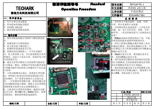
文件编号12E201609170011、所有焊点不能有假焊、连锡、空焊、半焊、焊点有刺等不良现象。
2、在焊接时要注意观查前一工序是否有问题,如:电子元件浮高、歪斜、少件、错件等。
(有这些情况请马上反映给拉长处理)3、PCBA板表面必须保持清洁干净,不能有明显的洗板水或助焊剂痕迹存在。
4、所有主机继电器输出都必须接上真实负载进行测试,保证继电器输出正常,不应许测试人员只听继电器跳动声判断继电器输出是否正常。
5、30A输出是否正常,调光输出是否正常,受控12V输出是否正常。
6、项目如需加层板的必须加装好加层板进行功能测试,且加层板继电器也必须接真实负载测试其是否为正常输出。
7、强电和弱电输出端子必须要测量正面螺丝处是否为正常输出输入,避免端子未插入PCB,导致该端子无作用。
工具/夹具检测工具/仪器品 质 要 求单机V3.1测试架测试灯箱泰格方舟科技有限公司一、作业前准备1、生产订单以及功能表2、所有配套的面板及配件3、单机V3.1测试架4、测试架配套面板连接线1、将所有配套面板以及配件与测试架连接好。
2、将测试架与灯箱连接好。
3、将主机安装于测试架上。
4、检测所有连接线是否正常。
5、将测试架电源线接上,并开启电源开关,给主机系统上电,并注意观察是否有异常情况,电流大小是否正常,发现异常立即关闭电源开关。
6、通电无异常后测试人员需依照功能表进行功能逐一测试,如测试中发现功能异常或不理解功能作用的时候立即通知生产拉长进行处理。
7、主机功能测试完成后,需要进行老化测试,单机版主机老化时间要求测试24小时,老化期间,生产需要安排相关人员进行巡查,一旦发现异常故障出现,需将问题记录且给到维修部进行维修,维修人员必须要把故障现象及处理方法记录维修报表上。
8、主机老化后需要再次测试一遍基本功能是否正常,测试OK后贴上PASS标签后,按要求摆放好,避免堆积摆放造成损坏。
二、操作步骤文件编号121、将所有配套面板以及配件与测试架连接好。
- 1、下载文档前请自行甄别文档内容的完整性,平台不提供额外的编辑、内容补充、找答案等附加服务。
- 2、"仅部分预览"的文档,不可在线预览部分如存在完整性等问题,可反馈申请退款(可完整预览的文档不适用该条件!)。
- 3、如文档侵犯您的权益,请联系客服反馈,我们会尽快为您处理(人工客服工作时间:9:00-18:30)。
Sample size: 2 finished products 样品数量:2 个成品(依据具体检测情况进行调整)
Hong Cai Testing Technology Co.,Ltd. 虹彩检测技术有限公司
总机: ( 86)755-84616666(86)755-89594491 网址: 地址:深圳市龙岗区龙平西路志达工业区鹏利泰工业园 D 栋(邮编:518116)
深圳虹彩检测技术有限公司 Shen Zhen Hong Cai Testing Technology Co.,Ltd.
HCT
Hong Cai Testing HCT-2010-03-RoHS- 03
XRF 扫描&全球市场或终端客户的管控而感到烦恼吗?
面临挑战
HCT 建议企业的应对措施如下:
一、加强供应商的品质控管 面对 RoHS 针对产品所规定的管制物质, 意味制造商必须对组成产品的元件、 材料 全面清查外,更须著手调查供应商采用的材料成分,而制造商对供应链的管理即 成为一项重要的考验。 为了符合 RoHS 等绿色规范的要求, 在尖端产品设计开发上 , 必须考虑到各项零配件的选择是否符合不含有相关有害物质的料件要求。目前一 般的做法是,要求下游供应商签俱不使用有害物质的保证书,并要求在出货时出 具第三方公正检测单位的测试报告。因材料零组件采购风险提高,增加材料管制 成本,面对层层的供应链,如何做好供应商的稽核管理以及进料品质监测,已是 各家厂商极须优先处理的重要课题。 二、建立快速简易检测方法 由于 X 射线荧光分析仪(XRF)具有非破坏、简便、测试时间短的优势,目前已经被 各大电子电机厂商采用。首先要建立进料检测品质管理标准;利用 XRF 作快速进 料筛选,以确保进料品质;对于争议性样品,一般做法是送请第三方公正检测机 构做进一步确认;建立 XRF 抽样检测机制; 出货检验∶一般利用携带式 XRF 作为 成品快速检验工具,以确保出货品质,若客户要求出示检测报告,则需要委托专 业的第三方公正检测机构检测并提供检测报告。
应对措施
深圳虹彩检测技术有限公司 Shen Zhen Hong Cai Testing Technology Co.,Ltd.
HCT
Hong Cai Testing HCT-2010-03-RoHS- 03
整机 RoHS 一站式检测特惠服务
作为业界的您是否正在为符合 RoHS 的要求而烦恼呢?是否正为寻 找优良整机检测方案而忙碌呢?或者,因为高昂的整机检测费用而却步 呢? 即日起,虹彩检测将为您提供更贴身的整机检测特惠方案,XRF 扫描筛 选结合精确化学测试,一步到位让您的产品满足 RoHS 符合性要求,真正 帮您省时、省钱、省心!
深圳虹彩检测技术有限公司 Shen Zhen Hong Cai Testing Technology Co.,Ltd.
HCT
Hong Cai Testing HCT-2010-03-RoHS- 03
近几十年来,全球电子电气工业呈现膨胀式发展。电子电气工业领域内的技术 更新越来越快,不断缩短着产品的升级换代周期。同时,电子产品的结构也呈 现出日趋复杂的势头。电子电气工业在给人类带来方便和益处的同时也给社会 带来堆积如山的电子垃圾,世界各国处理报废电子电气产品的负担越来越重。 电子电气垃圾给全球生态环境造成的消极影响正越发严峻。 作为供应链末端的整机产品和复杂功能模块的生产企业,必将面临供应商数量 众多所带来的高昂测试成本,以及供应链复杂难控所引起的风险。 在电子零组件产业与系统组装业中,很多厂商都曾收过客户要求提供产品所含 限用物质的问卷表,或提供产品不含禁用物质的保证书。这些国际大厂及其国 内电子电气产品厂商开始积极推动绿色制造,一方面是由于国际社会对于企业 在环境保护上所做的努力日益受到重视,另一方面则是国际间因环境议题所建 立的非关税之技术性贸易障碍,例如:欧盟委员会颁布的《关于报废电子电气 设备指令》 ( WEEE 指令)和《关于在电子电气设备中限制使用某些有害物质指 令》 ( RoHS 指 令 ) 。如果产品不能符合回收再利用和特定有害物质管制的要求, 可能会面对重大赔偿损失,根本无法进入欧洲市场。所涉及的层面从产品设计、 生产制程,到物料采购、管理及品质控管机制与后阶段的服务,影响层面相当 深远,这是目前各大厂商所面临的重要挑战。
我们将对整机产品进行科学合理的拆分归类,并 为 HCT 出版物,本出版物所提供技术信息,并不应视为对所涉 确定测试部位点数,使检测费用降至最低!!!!
Hong Cai Testing Technology Co.,Ltd. 虹彩检测技术有限公司
总机: ( 86)755-84616666(86)755-89594491 网址: 地址:深圳市龙岗区龙平西路志达工业区鹏利泰工业园 D 栋(邮编:518116)
HCT 推出 XRF 预测试+Chemical 化学分析的一站式测试服务,一步到位,一次性解决成品及半成 品的管控带来的困扰。
HCT 整机验证服务是根据 IEC62321 和欧盟 RoHS 执行指引文件,将样品拆分成均一材质后进行 XRF 扫 描 , 参考扫描结果和申请者提交的原材料测试报告,对高危和疑似部位采用精密化学测试作进一步的确认,以验 证样品是否符合 RoHS 要求。 整机产品的 RoHS 符合性,取决于整机中的每个均质材质是否符合 RoHS 要求。整机生产商往往需要在新产品 上线前,对整机进行验证,而不仅仅是测试整机上的部分零部件。HCT 的整机验证服务正是通过对整机产品 进行必要测试,并结合其他验证方法,最终给予整机产品做出是否符合 RoHS 的判断结论。 制造商通过该项服务,可在稽查供应商普通化学测试结果的同时,降低自身的风险;不仅使产品符合性文件 简单化,还能有效降低自身准备符合性文件的成本和时间,大大节约相关的人力资源、系统资源和避免重复 性的测试。使用 HCT 的整机验证报告,也将大大加强贸易商(买家)的信心,贸易商在向消费者展示产品质 量的时候,整机验证报告可以做为产品制造商在产品质量安全上所作努力的直接证明,进而吸引和打动消费 者,增加产品在全球各地的销量。 声明: 更多测试详情请联系我们……
NO.of Testing point 检测点数(部位点数) <25 26-50 51-100 101-150 151-200 201-250 每增加 50 个检测点 package price(RMB) 优惠价格 +Chemical 化 学 分析 ) (XRF 扫描 扫描+Chemical 2800 3000 5000 8000 12000 15000 加 3000 Working day 检测周期(工作日) 4-5 5 44-5 4-5 4-5 5-7 5-7 /
�企业� Challenge Solution
Hong Cai Testing Technology Co.,Ltd. 虹彩检测技术有限公司
总机: ( 86)755-84616666(86)755-89594491 网址: 地址:深圳市龙岗区龙平西路志达工业区鹏利泰工业园 D 栋(邮编:518116)
©2010 HCT 版权所有 本刊所有内容, 均属 HCT 所有, 如无 HCT 预先书面同意,请勿引用或涉及本刊物所包含的信息。本信息 及的题目的详尽论述。本刊物具有教育性,并不可以取代任何 法律要求或适用规则。本刊物并不再提供咨询或专业建议。本 刊物所包含的信息将不再更改。 HCT 不保证本刊物所包含的内容 没有任何错误或能够满足任何特定的性能或质量标准。
