品保系统FM-QA-002(A0)
ESA620电气安全分析仪商品说明书
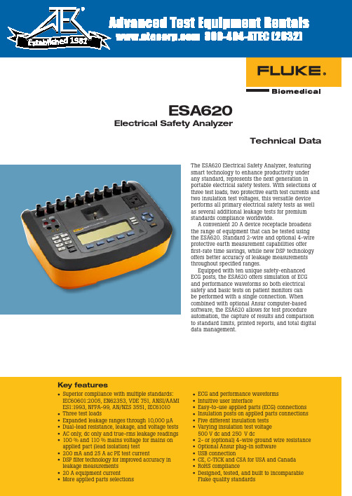
Electrical Safety Analyzer• Superior compliance with multiple standards:IEC60601:2005, EN62353, VDE 751, ANSI/AAMI ES1:1993, NFPA-99, AN/NZS 3551, IEC61010 • Three test loads• Expanded leakage ranges through 10,000 µA • Dual-lead resistance, leakage, and voltage tests • AC only, dc only and true-rms leakage readings • 100 % and 110 % mains voltage for mains on applied part (lead isolation) test • 200 mA and 25 A ac PE test current• DSP filter technology for improved accuracy in leakage measurements • 20 A equipment current• More applied parts selections• ECG and performance waveforms • Intuitive user interface• Easy-to-use applied parts (ECG) connections • Insulation posts on applied parts connections • Five different insulation tests • Varying insulation test voltage500 V dc and 250 V dc• 2- or (optional) 4-wire ground wire resistance • Optional Ansur plug-in software • USB connection• CE, C-TICK and CSA for USA and Canada • RoHS compliance• Designed, tested, and built to incomparable Fluke quality standardsTechnical DataThe ESA620 Electrical Safety Analyzer, featuring smart technology to enhance productivity under any standard, represents the next generation in portable electrical safety testers. With selections of three test loads, two protective earth test currents and two insulation test voltages, this versatile device performs all primary electrical safety tests as well as several additional leakage tests for premium standards compliance worldwide.A convenient 20 A device receptacle broadens the range of equipment that can be tested using the ESA620. Standard 2-wire and optional 4-wire protective earth measurement capabilities offer first-rate time savings, while new DSP technology offers better accuracy of leakage measurements throughout specified ranges.Equipped with ten unique safety-enhanced ECG posts, the ESA620 offers simulation of ECG and performance waveforms so both electrical safety and basic tests on patient monitors can be performed with a single connection. When combined with optional Ansur computer-based software, the ESA620 allows for test procedure automation, the capture of results and comparison to standard limits, printed reports, and total digital data management.Key featuresSpecifications2 Fluke Biomedical ESA620 Electrical Safety Analyzer*No-cost extended warranty available after first-year calibration at any Fluke Biomedical authorized service center.ESA620 Electrical Safety Analyzer Fluke Biomedical 3Models2785725 ESA620 Electrical Safety Analyzer US, 115 V 20 A 3051408 ESA620 Electrical Safety Analyzer EUR, 230 V 3051390 ESA620 Electrical Safety Analyzer FR, 230 V 3051413 ESA620 Electrical Safety Analyzer ISR, 230 V 3051424 ESA620 Electrical Safety Analyzer ITA, 230 V 3051436 ESA620 Electrical Safety Analyzer AUS, 230 V 3051449 ESA620 Electrical Safety Analyzer UK, 230 V 3051451 ESA620 Electrical Safety Analyzer SWI, 230 VStandard accessories2814967 Operator’s Manual CD2814971 Multilingual Getting Started Guide 2195732 15 A to 20 A Adapter (USA only) 2814980 Carrying Case 1626219 Data Transfer Cable Power Cord (country specific)ESA620 Accessory Kit (country specific)Optional accessories3116463 Ansur ESA620 Plug-In 1903307 Retractable Test Leads 2242165 Ground Pin Adapter2067864 Kelvin Cable Set for 4-Wire MeasurementOrdering informationFluke Biomedical.Better products. More choices. One company.Fluke Biomedical 6045 Cochran RoadCleveland, OH 44139-3303 U.S.A.Fluke Biomedical Europe Science Park Eindhoven 5110 5692EC Son, The NetherlandsFor more information, contact us:In the U.S.A. (800) 850-4608 or Fax (440) 349-2307In Europe/M-East/Africa +31 40 267 5435 or Fax +31 40 267 5436From other countries +1 (440) 248-9300 or Fax +1 (440) 349-2307Email:*************************Web access: ©2007-2008 Fluke Biomedical. Specifications subject to change without notice. Printed in U.S.A. 9/2008 3086339 D-EN-N Rev CModification of this document is not permitted without written permission from Fluke Corporation.About Fluke Biomedicalfor all your equipment calibration needs.range of software and hardware tools to meet today’s challenges.Fluke Biomedical Regulatory Commitmentcertified and our products are:• CE Certified, where required • NIST Traceable and Calibrated• UL, CSA, ETL Certified, where required • NRC Compliant, where required。
电子厂电子产品品保部可靠性试验作业指导书-经典
毅力電子貿易有限公司電威電子有限公司電科電子有限公司品質系統工作指導書(ISO9001:2000)文件名稱:可靠性試驗工作指導書文件編號﹕NL-QUA-WI—04發行日期:Aug.01。
2002控制碼﹕NL-MAN-F051.0目的為確保公司所有產品的質量達到國際標準或客戶要求,特制定本文件闡述對有關產品進行可靠性試驗的工作指引,以確保各產品的可靠性試驗項目均能按規定執行, 並使公司產品達到具有高度可靠及安全性能的目的。
2.0适用范圍本文件适用于本公司品管部及對本公司所有開發及生產的產品進行可靠性試驗(包括原材料)。
3.0用語定義3.1可靠性試驗:指對本公司開發的產品在量產前(即試產後)、量產中,或產品的原材料物件進行的各種可靠性試驗,以確保產品能夠滿足客戶的要求,並符合安全性、耐久性、適用於目的地區使用性,在一般環境下操作或運輸過程中不容易被損壞等情況。
產品改良後或原材料試驗需經總管級以上批准。
可靠性試驗項目類別一般分為以下九大類:a.一般動作檢驗:產品在試驗前及試驗後,必須在常溫下進行外觀及性能等檢測,檢測的方法、標準按品管部要求[詳細請參閱《品管部工作指導書(QC)》NL-QUA-WI-02]。
b.環境試驗:對產品在高溫高濕、低溫環境流通或使用時的外觀及性能進行檢測,並與常溫檢驗標準作比較.c.運輸模擬試驗:對產品在運輸過程中所受振動及沖擊等破壞程度的測試.d.安全性能試驗:對高壓、絕緣和內部安全性能的測試.e.耐久性試驗:對產品零部件壽命、零部件強度進行測試.f.防腐蝕試驗:對產品外殼絲印、噴油顏色及螺絲、拉杆天線等金屬零部件防腐蝕能力進行測試。
g.老化性試驗:對產品進行加/減電壓、常電壓連績老化測試。
h.靜電試驗:用模擬靜電發生器對產品進行靜電放電破壞測試。
i.cd抗震能力測試:對產品cd防震能力進行測試。
3.2室溫:又稱常溫, 通常指在20℃~26℃範圍。
4.0權責4.1品管部經理a.負責統籌可靠性試驗室的一切運作, 確保本公司產品質量均能達到安全可靠的目的。
ABBsacef2智能断路器铭牌说明

ABBsacef2智能断路器铭牌说明ABBsacef2智能断路器是一种智能电气设备,用于保护电路免受过电流、过载和短路等电气故障的影响。
铭牌是指安装在设备上的标识板,用于提供有关设备的详细信息和规格。
以下是ABBsacef2智能断路器铭牌的详细说明:1. 设备名称:ABBsacef2智能断路器2.型号:根据具体型号进行标识,例如F200、F320等等。
3.额定电压:指断路器能够正常工作的电压范围,一般为AC220V或AC380V,具体根据型号而定。
4.额定电流:指断路器能够承受和断开的最大电流,一般为几十安培至几千安培,具体根据型号而定。
5.额定短路切断能力:指断路器在短路故障时能够迅速切断电流的能力,一般以短路电流值来表示,例如20KA、36KA等等。
6.断路器类型:指断路器的工作原理和结构,例如空气断路器、真空断路器等。
8.制造日期:指断路器的生产日期,用于确定产品的使用寿命和维修周期。
9.其他参数:根据具体型号,可能还包括额定频率、使用环境条件、重量、尺寸等信息。
除了上述基本信息,铭牌可能还包括其他有关断路器的详细技术参数和性能指标。
这些参数可能包括过电流保护特性、额定短路开断时间、断路器的操作方式、远程控制功能等等。
这些信息可以帮助用户更好地了解断路器的功能和可靠性,从而更好地应用它们于电气系统中。
值得注意的是,断路器铭牌上的信息应该清晰可见,不易磨损和褪色。
用户在购买断路器时,应确保铭牌上的信息与实际需求相符,并且在安装和使用过程中,要定期检查和验明铭牌上的信息是否完好无损。
总结而言,ABBsacef2智能断路器铭牌提供了关键的设备信息,帮助用户选择和使用断路器。
用户在购买和使用断路器时,应仔细阅读并理解铭牌上的相关信息,以确保电路的安全和可靠性。
西门子G120C变频器说明书
SINAMICS SINAMICS G120C变频器入门指南版本 03/2013,固件 V4.4 03/2013, FW 4.4法律资讯警告提示系统为了您的人身安全以及避免财产损失,必须注意本手册中的提示。
人身安全的提示用一个警告三角表示,仅与财产损失有关的提示不带警告三角。
警告提示根据危险等级由高到低如下表示。
当出现多个危险等级的情况下,每次总是使用最高等级的警告提示。
如果在某个警告提示中带有警告可能导致人身伤害的警告三角,则可能在该警告提示中另外还附带有可能导致财产损失的警告。
合格的专业人员本文件所属的产品/系统只允许由符合各项工作要求的合格人员进行操作。
其操作必须遵照各自附带的文件说明,特别是其中的安全及警告提示。
由于具备相关培训及经验,合格人员可以察觉本产品/系统的风险,并避免可能的危险。
Siemens 产品请注意下列说明:商标所有带有标记符号®的都是西门子股份有限公司的注册商标。
标签中的其他符号可能是一些其他商标,这是出于保护所有者权利的目地由第三方使用而特别标示的。
责任免除我们已对印刷品中所述内容与硬件和软件的一致性作过检查。
然而不排除存在偏差的可能性,因此我们不保证印刷品中所述内容与硬件和软件完全一致。
印刷品中的数据都按规定经过检测,必要的修正值包含在下一版本中。
Siemens AG Industry Sector Postfach 48 48 90026 NÜRNBERG 德国A5E02999802A AR08/2011Copyright © Siemens AG 2011.本公司保留技术更改的权利P目录1 安全注意事项 (5)2 引言 (7)2.1变频器 SINAMICS G120C (7)2.2调试用工具 (8)3 安装 (9)3.1尺寸 (9)3.2功率接口 (11)连接过程和用户接口 (13)3.3变频器上的端子台 (14)3.4定义的输入/输出配置 (15)3.54 调试 (19)4.1 BOP-2 的菜单结构 (20)4.2基本调试 (21)4.3自由选择参数,修改参数 (22)4.4修改端子的功能 (23)使能“Safe Torque Off” (24)4.5订购 GSD 文件 (24)4.65 参数表 (25)6 故障排除 (39)故障和警告列表 (39)6.1其它信息 (44)6.2变频器目录变频器变频器安全注意事项机床制造商必须确保,一旦达到最低故障电流,主电源侧的过电流保护装置便能在 5 秒内切断电源,最低故障电流是指在绝缘完全损坏时、流向在运行时没有通电的可触碰导电部件和最大电流回路电阻的电流,过电流保护装置应该固定安装,或装入固定安装的部件中。
LCR-1000 LCR Meter 用户手册说明书

用户手册User’s GuideAT827/AT828Rev.A0固件说明:适用于主程序RevA1.0及以上的版本@Instruments常州安柏精密仪器有限公司.江苏省常州市武进区漕溪路9号14幢电话:*************销售服务电子邮件: *****************技术支持电子邮件: ****************©2005-2023 Applent Instruments Ltd.2 LCR-1000 LCR Meter用户手册目录目录 (2)插图目录 (5)表格目录 (6)1.安装和设置向导 (7)1.1装箱清单 (7)1.2电源要求 (7)1.3操作环境 (7)1.4清洗 (7)1.5更换电池 (8)2.概述 (9)2.1引言 (9)2.2测量功能 (9)2.2.1测量参数 (9)2.2.2等效方式 (10)2.2.3量程 (10)2.2.4测试速度 (10)2.2.5基本准确度 (11)2.2.6测量显示范围 (11)2.3信号源 (12)2.3.1测试频率 (12)2.3.2测试电平 (12)2.3.3源内阻 (12)2.4主要功能 (12)2.4.1校准功能 (12)2.4.2比较器功能 (12)2.4.3系统设置 (12)2.4.4接口 (12)3.开始 (13)3.1前面板 (13)3.2接口 (14)3.2.1电池充电功能 (14)3.3开机 (15)3.4测试端的连接 (15)4.[MEAS DISPLAY] 测量页面 (16)4.1[MEAS DISPLAY] - 测量显示页 (16)4.1.1FUNC - 测量功能 (16)4.1.2FREQ - 测试频率 (17)4.1.3LEVEL - 测试电平 (17)4.1.4RANGE - 测试量程 (17)3安装和设置向导4.1.5 SPEED - 测试速度 ............................................................................ 18 4.1.6 EQU - 等效方式 ................................................................................. 18 4.1.7HOLD – 数据保持 (19)5.[SETUP] 设置页面 ........................................................................................................................ 20 5.1[SETUP] 设置页 .................................................................................................... 20 5.1.1 AUTO LCZ – 自动LCZ 选择 .............................................................. 20 5.1.2 COMP - 比较器开关 .......................................................................... 21 5.1.3 BEEP - 讯响设置 ............................................................................... 21 5.1.4 NOMINAL - 输入[标称值] ................................................................... 22 5.1.5TOL - 输入百分比偏差 (23)6. [OPEN SHORT] 清零页面 ............................................................................................................ 24 6.1 [OPEN SHORT] 清零页 ........................................................................................ 24 6.2 [OPEN TEST]-开路校准 ......................................................................................... 24 6.3 [短路]校准.............................................................................................................. 25 7. [SYST]系统配置页面 (27)7.1[SYSTEM CONFIG] 系统配置页 ............................................................................ 27 7.1.1 KEY BEEP - 按键音开关 .................................................................... 27 7.1.2 BRIGHTNESS – LCD 背光亮度调整 .................................................. 28 7.1.3 TOUCH PANEL – 触摸屏设置 ............................................................ 28 7.1.4 DIM DISPLAY - 降低背光亮度时间设置 .............................................. 30 7.1.5 APO – 自动关机时间设置 .................................................................. 30 7.1.6 VCOM ENDMARK – USB 虚拟串口结束符 ......................................... 31 7.1.7 USB-HID PID – 产品ID 设置 ............................................................ 32 7.1.8 DEFAULT SET – 恢复出厂设置 (32)7.2 [SYSTEM INFORMATION] 系统信息页 (32)8. 测量步骤及示例 ............................................................................................................................. 34 8.1 测量示例 (34)9.远程控制及指令集 (36)9.1 USB-HID 设备类 .................................................................................................... 36 9.2 USB-HID 编程指南 ................................................................................................ 36 9.3 USB-VCOM 虚拟串口 . (38)9.4 指令集 (39)9.4.1 USB-HID 命令包 ................................................................................ 39 9.4.2 说明符 ............................................................................................... 40 9.4.3 数据类型 ............................................................................................ 40 9.5 命令参考 (41)9.5.1 DISP 显示子系统 ............................................................................... 41 9.5.2 FUNC 功能子系统 .............................................................................. 42 9.5.3 FREQ 频率子系统 ............................................................................. 44 9.5.4 APER 速度子系统 ............................................................................. 44 9.5.5 FETC? 查询结果子系统 ..................................................................... 44 9.5.6COMP 比较器子系统 (45)4 LCR-1000 LCR Meter用户手册9.5.7CORR 校准子系统 (46)9.5.8SYST 系统设置子系统 (48)9.5.9IDN?子系统 (48)9.5.10ERR错误子系统 (49)9.6命令汇总 (49)10.规格 (51)10.1一般规格 (51)10.2准确度 (52)10.3准确度 (52)10.3.1电容C及损耗D (52)10.3.2电感L和品质因数 (54)10.3.3阻抗Z与相位角θ (55)10.3.4ESR (55)10.3.5DCR (55)10.4外形尺寸 (56)安装和设置向导5插图目录图1-1 更换电池 (8)图3-1 前面板 (13)图3-2接口挡板 (14)图3-3充电指示灯,充电时显示为橙色 (14)图3-4测试端的连接 (15)图4-1 [MEAS DISPLAY]页 (16)图4-2 [HOLD]数据保存功能 (19)图5-1[SETUP] 页 (20)图5-2键盘输入框 (22)图6-1[OPEN SHORT] 页 (24)图6-2杂散导纳 (24)图6-3剩余阻抗 (25)图7-1<系统配置>页 (27)图7-2亮度调节键 (28)图7-3<系统配置>页 (32)图8-1电容器的测试结果 (34)图9-1在计算机上,仪器被识别为GW Intek HID (36)图9-2在仪器上,在底部提示行显示USB Attached (36)图9-3Windows 主机访问USB-HID设备流程图 (37)6 LCR-1000 LCR Meter用户手册表格目录表2-1 串并联等效电路 (10)表2-2 AT827测量显示范围 (11)表2-3 AT828 测量显示范围 (11)表3-1 前面板功能描述 (14)表3-2 接口挡板描述 (14)表4-1测试量程说明 (17)表4-2 量程与对应的测试范围 (18)表9-1一个指令发送包数据 (39)表9-2说明符 (40)表9-3数据格式列表 (40)表9-4倍率 (40)表9-5错误代码及信息 (49)表9-6所有USB命令汇总 (49)安装和设置向导71. 安装和设置向导感谢您购买我公司的产品!使用前请仔细阅读本章。
海浦蒙特MT70故障子码(1)
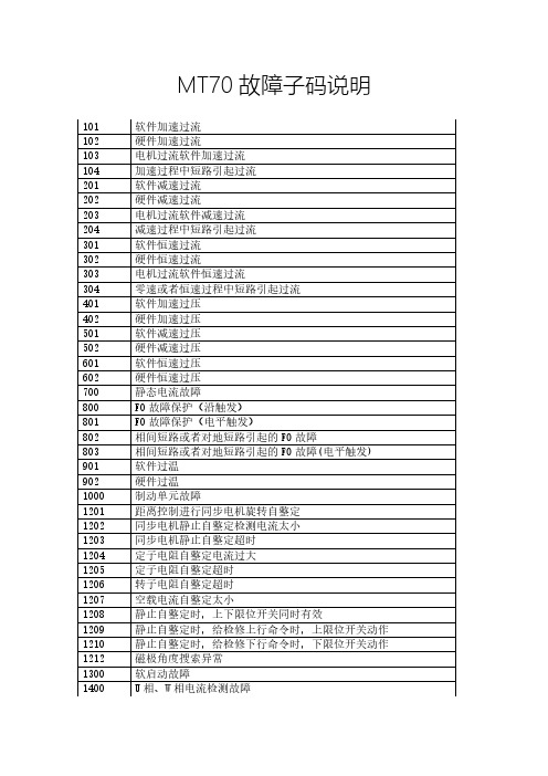
板载 E2prom 写操作超时 永磁同步曳引机自整定选择 F07.06 异步曳引机自整定选择 F10.10 F04.02 > F19.07 F04.02 > F19.08 F04.02 > F19.09 F04.02 > F19.10 F04.02 > F19.11 F19.07 < 0.100m/s F19.08 < 0.100m/s F19.09 < 0.100m/s F19.10 < 0.100m/s F19.11 < 0.100m/s 消防基站对应门机设为非服务层 第二消防基站对应门机设为非服务层 空闲基站对应门机设为非服务层 锁梯基站对应门机设为非服务层 永磁同步曳引机时 F11.00 设为 1 曳引机额定电流设定为 0 F07.11 > F07.02 F08.04 > F08.05 电梯实偏层与最大楼层总和大于 48 层 门机 1 分时不服务与门机 2 分时不服务同时有效 MCB-A 设置了 MT70-PG4-SC 编码器卡 门机 1 分时不服务时间设置错误 轿顶板多功能输入端子设置有 33 号设置重复 轿顶板多功能输入端子设置有 34 号设置重复 轿顶板多功能输入端子设置有 35 号设置重复 轿顶板多功能输入端子设置平层信号不在一起 同步电机选择 F00.01 = 0 或者 1 参数组读取越界 磁栅尺下限位高度异常 非检修下进行磁栅尺模式设置 磁栅尺设置楼层非当前楼层 磁栅尺模式设置异常 同时设置多种测试模式( MYKL 非标) 输入电压检测故障 编码器反向故障 静止自整定配 UVW 编码器检测到编码器反向故障 静止自整定配 SINCOS 编码器检测到编码器反向故障 编码器反向故障 编码器 AB 断线 自整定 SINCOS 编码器 C+、C-断线
西门子PowerFlex 523变频器说明书

On Drive GuidePowerFlex 523 Adjustable Frequency AC Drive Parameter GroupsBasic Display b Output Freq b001 Commanded Freq b002 Output Current b003 Output Voltage b004 DC Bus Voltage b005Drive Status b006Fault 1 Code b007Fault 2 Code b008Fault 3 Code b009Process Display b010Control Source b012Contrl In Status b013Dig In Status b014Output RPM b015Output Speed b016Output Power b017Power Saved b018Elapsed Run Time b019Average Power b020Elapsed kWh b021Elapsed MWh b022Energy Saved b023Accum kWh Sav b024Accum Cost Sav b025Accum CO2 Sav b026Drive Temp b027Control Temp b028Control SW Ver b029Basic Program P Language P030 Motor NP Volts P031 Motor NP Hertz P032 Motor OL Current P033Motor NP FLA P034Motor NP Poles P035Motor NP RPM P036Voltage Class P038Torque Perf Mode P039Autotune P040Accel Time 1P041Decel Time 1P042Minimum Freq P043Maximum Freq P044Stop Mode P045Start Source 1P046Speed Reference1P047Start Source 2P048Speed Reference2P049Start Source 3P050Speed Reference3P051Average kWh Cost P052Reset To Defalts P053Terminal Blocks t DigIn TermBlk 02t062 DigIn TermBlk 03t063 2-Wire Mode t064 DigIn TermBlk 05t065DigIn TermBlk 06t066Relay Out1 Sel t076Relay Out1 Level t077Relay 1 On Time t079Relay 1 Off Time t080EM Brk Off Delay t086EM Brk On Delay t087Anlg In 0-10V Lo t091Anlg In 0-10V Hi t092Anlg In V Loss t094Anlg In4-20mA Lo t095Anlg In4-20mA Hi t096Anlg In mA Loss t097Anlg Loss Delay t098Analog In Filter t099Sleep-Wake Sel t100Sleep Level t101Sleep Time t102Wake Level t103Wake Time t104Communications C Comm Write Mode C121 RS485 Data Rate C123 RS485 Node Addr C124 Comm Loss Action C125Comm Loss Time C126RS485 Format C127Opt Data In 1C161Opt Data In 2C162Opt Data In 3C163Opt Data In 4C164Opt Data Out 1C165Opt Data Out 2C166Opt Data Out 3C167Opt Data Out 4C168MultiDrv Sel C169Drv 1 Addr C171Drv 2 Addr C172Drv 3 Addr C173Drv 4 Addr C174DSI I/O Cfg C175Advanced Display d Analog In 0-10V d360 Analog In 4-20mA d361 Elapsed Time-hr d362Elapsed Time-min d363Counter Status d364Timer Status d365Timer StatusF d366Drive Type d367Testpoint Data d368Motor OL Level d369Slip Hz Meter d375Speed Feedback d376DC Bus Ripple d380Output Powr Fctr d381Torque Current d382PID1 Fdbk Displ d383PID1 Setpnt Displ d384Fiber Status d390Advanced Program A Preset Freq 0A410 Preset Freq 1A411 Preset Freq 2A412 Preset Freq 3A413 Preset Freq 4A414 Preset Freq 5A415 Preset Freq 6A416 Preset Freq 7A417 Keypad Freq A426 MOP Freq A427 MOP Reset Sel A428 MOP Preload A429 MOP Time A430 Jog Frequency A431 Jog Accel/Decel A432 Purge Frequency A433 DC Brake Time A434DC Brake Level A435DC Brk Time@Strt A436DB Resistor Sel A437DB Threshold A438S Curve %A439PWM Frequency A440Accel Time 2A442Decel Time 2A443Accel Time 3A444Decel Time 3A445Accel Time 4A446Decel Time 4A447Skip Frequency 1A448Skip Freq Band 1A449Skip Frequency 2A450Skip Freq Band 2A451PID 1 Trim Hi A456PID 1 Trim Lo A457PID 1 Trim Sel A458PID 1 Ref Sel A459PID 1 Fdback Sel A460PID 1 Prop Gain A461PID 1 Integ Time A462PID 1 Diff Rate A463PID 1 Setpoint A464PID 1 Deadband A465PID 1 Preload A466PID 1 Invert Err A467Process Disp Lo A481Process Disp Hi A482Testpoint Sel A483Current Limit 1A484Shear Pin1 Level A486Shear Pin 1 Time A487Stall Fault Time A492Motor OL Select A493Motor OL Ret A494Drive OL Mode A495IR Voltage Drop A496Flux Current Ref A497Boost Select A530Start Boost A531Break Voltage A532Break Frequency A533Maximum Voltage A534Pulse In Scale A537Var PWM Disable A540Auto Rstrt Tries A541Auto Rstrt Delay A542Start At PowerUp A543Reverse Disable A544Flying Start En A545FlyStrt CurLimit A546Compensation A547Power Loss Mode A548Half Bus Enable A549Bus Reg Enable A550Fault Clear A551Program Lock A552Program Lock Mod A553Drv Ambient Sel A554Reset Meters A555Text Scroll A556Out Phas Loss En A557Max Traverse A567Traverse Inc A568Traverse Dec A569P Jump A570Sync Time A571Speed Ratio A572Network N This group contains parameters for the network option card that is installed.Additional parameters are listed on the next page.2 PowerFlex 523 Adjustable Frequency AC DriveAppView Parameter GroupsModifiedM This group contains parameters that have their values changed from the factory default.Fault and Diagnostic F Fault 4 Code F604Fault 5 Code F605Fault 6 Code F606Fault 7 Code F607Fault 8 Code F608Fault 9 Code F609Fault10 Code F610Fault 1 Time-hr F611Fault 2 Time-hr F612Fault 3 Time-hr F613Fault 4 Time-hr F614Fault 5 Time-hr F615Fault 1 Time-min F621Fault 2 Time-min F622Fault 3 Time-min F623Fault 4 Time-min F624Fault 5 Time-min F625Fault 1 Freq F631Fault 2 Freq F632Fault 3 Freq F633Fault 4 Freq F634Fault 5 Freq F635Fault 1 Current F641Fault 2 Current F642Fault 3 Current F643Fault 4 Current F644Fault 5 Current F645Fault 1 BusVolts F651Fault 2 BusVolts F652Fault 3 BusVolts F653Fault 4 BusVolts F654Fault 5 BusVolts F655Status @ Fault 1F661Status @ Fault 2F662Status @ Fault 3F663Status @ Fault 4F664Status @ Fault 5F665Comm Sts - DSI F681Comm Sts - Opt F682DSI I/O Act F686Drv 0 Logic Cmd F705Drv 0 Reference F706Drv 0 Logic Sts F707Drv 0 Feedback F708Drv 1 Logic Cmd F709Drv 1 Reference F710Drv 1 Logic Sts F711Drv 1 Feedback F712Drv 2 Logic Cmd F713Drv 2 Reference F714Drv 2 Logic StsF715Drv 2 Feedback F716Drv 3 Logic Cmd F717Drv 3 Reference F718Drv 3 Logic Sts F719Drv 3 Feedback F720Drv 4 Logic Cmd F721Drv 4 Reference F722Drv 4 Logic Sts F723Drv 4 Feedback F724DSI Errors F731Conveyor G1Language P030Output Freq b001Commanded Freq b002Motor NP Volts P031Motor NP Hertz P032Motor OL Current P033Motor NP FLA P034Motor NP Poles P035Autotune P040Accel Time 1P041Decel Time 1P042Minimum Freq P043Maximum Freq P044Stop Mode P045Start Source 1P046Speed Reference1P047DigIn TermBlk 02t062DigIn TermBlk 03t063Relay Out1 Sel t076Anlg In 0-10V Lo t091Anlg In 0-10V Hi t092Anlg In4-20mA Lo t095Anlg In4-20mA Hi t096Anlg In mA Loss t097Slip Hz Meter d375Preset Freq 0A410Jog Frequency A431Jog Accel/Decel A432S Curve %A439Reverse DisableA544Mixer G2Language P030Output Freq b001Commanded Freq b002Output Current b003Motor NP Volts P031Motor NP Hertz P032Motor OL Current P033Motor NP FLA P034Motor NP Poles P035Autotune P040Accel Time 1P041Decel Time 1P042Minimum Freq P043Maximum Freq P044Stop Mode P045Start Source 1P046Speed Reference1P047Relay Out1 Sel t076Anlg In 0-10V Lo t091Anlg In 0-10V Hi t092Anlg In4-20mA Lo t095Anlg In4-20mA Hi t096Anlg In mA Losst097Preset Freq 0A410Stall Fault Time A492Compressor G3Language P030Output Freq b001Commanded Freq b002Motor NP Volts P031Motor NP Hertz P032Motor OL Current P033Motor NP FLA P034Motor NP Poles P035Autotune P040Accel Time 1P041Decel Time 1P042Minimum FreqP043Maximum FreqP044Stop Mode P045Start Source 1P046Speed Reference1P047Relay Out1 Sel t076Anlg In 0-10V Lo t091Anlg In 0-10V Hi t092Anlg In4-20mA Lo t095Anlg In4-20mA Hi t096Anlg In mA Loss t097Preset Freq 0A410Auto Rstrt Tries A541Auto Rstrt Delay A542Start At PowerUp A543Reverse Disable A544Power Loss Mode A548Half Bus Enable A549Centrifugal Pump G4Language P030Output Freq b001Commanded Freq b002Motor NP Volts P031Motor NP Hertz P032Motor OL Current P033Motor NP FLA P034Motor NP Poles P035Autotune P040Accel Time 1P041Decel Time 1P042Minimum Freq P043Maximum Freq P044Stop Mode P045Start Source 1P046Speed Reference1P047Relay Out1 Sel t076Anlg In 0-10V Lo t091Anlg In 0-10V Hi t092Anlg In4-20mA Lo t095Anlg In4-20mA Hi t096Anlg In mA Loss t097Preset Freq 0A410PID 1 Trim Hi A456PID 1 Trim Lo A457PID 1 Ref Sel A459PID 1 Fdback Sel A460PID 1 Prop Gain A461PID 1 Integ Time A462PID 1 Diff Rate A463PID 1 Setpoint A464PID 1 Deadband A465PID 1 Preload A466Auto Rstrt Tries A541Auto Rstrt Delay A542Start At PowerUp A543Reverse Disable A544Blower/Fan G5Language P030Output Freq b001Commanded Freq b002Motor NP Volts P031Motor NP Hertz P032Motor OL Current P033Motor NP FLAP034Motor NP Poles P035Autotune P040Accel Time 1P041Decel Time 1P042Minimum Freq P043Maximum Freq P044Stop Mode P045Start Source 1P046Speed Reference1P047Relay Out1 Sel t076Anlg In 0-10V Lo t091Anlg In 0-10V Hi t092Anlg In4-20mA Lo t095Anlg In4-20mA Hi t096Anlg In mA Loss t097Preset Freq 0A410PID 1 Trim Hi A456PID 1 Trim Lo A457PID 1 Ref Sel A459PID 1 Fdback Sel A460PID 1 Prop Gain A461PID 1 Integ Time A462PID 1 Diff Rate A463PID 1 Setpoint A464PID 1 Deadband A465PID 1 Preload A466Auto Rstrt Tries A541Auto Rstrt Delay A542Start At PowerUp A543Reverse Disable A544Flying Start En A545Additional groups are listed on the next page.PowerFlex 523 Adjustable Frequency AC Drive 3CustomView Parameter GroupFault DescriptionsExtruder G6Language P030Output Freq b001Commanded Freq b002Output Current b003Motor NP Volts P031Motor NP Hertz P032Motor OL Current P033Motor NP FLA P034Motor NP Poles P035Autotune P040Accel Time 1P041Decel Time 1P042Minimum Freq P043Maximum Freq P044Stop Mode P045Start Source 1P046Speed Reference1P047Relay Out1 Sel t076Anlg In 0-10V Lo t091Anlg In 0-10V Hi t092Anlg In4-20mA Lo t095Anlg In4-20mA Hi t096Anlg In mA Loss t097Slip Hz Meter d375Speed Feedback d376Preset Freq 0A410Stall Fault Time A492Pulse In Scale A537Power Loss Mode A548Half Bus Enable A549Textile/Fiber G8Language P030Output Freq b001Commanded Freq b002Motor NP Volts P031Motor NP Hertz P032Motor OL Current P033Motor NP FLA P034Motor NP Poles P035Autotune P040Accel Time 1P041Decel Time 1P042Minimum Freq P043Maximum Freq P044Stop Mode P045Start Source 1P046Speed Reference1P047DigIn TermBlk 02t062DigIn TermBlk 03t063Relay Out1 Sel t076Anlg In 0-10V Lo t091Anlg In 0-10V Hi t092Anlg In4-20mA Lo t095Anlg In4-20mA Hi t096Anlg In mA Loss t097Slip Hz Meter d375Fiber Status d390Preset Freq 0A410Jog Frequency A431Jog Accel/Decel A432S Curve %A439Reverse Disable A544Power Loss Mode A548Half Bus Enable A549Bus Reg Enable A550Max Traverse A567Traverse Inc A568Traverse Dec A569P Jump A570Sync Time A571Speed Ratio A572CustomGCThis group can store up to 100 of your frequently used parameters for your application.No.Fault Type (1)Description ActionF000No Fault –No fault present.–F002Auxiliary Input 1External trip (Auxiliary) input.•Check remote wiring.•Verify communications programming for intentional fault.F003Power Loss 2Single phase operation detected with excessive load.•Monitor the incoming AC line for low voltage or line power interruption.•Check input fuses.•Reduce load.F004UnderVoltage 1DC bus voltage fell below the minimum value.Monitor the incoming AC line for low voltage or line powerinterruption.F005OverVoltage1DC bus voltage exceeded maximum value.Monitor the AC line for high line voltage or transient conditions. Busovervoltage can also be caused by motor regeneration. Extend thedecel time or install dynamic brake option.F006Motor Stalled 1Drive is unable to accelerate or decelerate motor.•Increase P041, A442, A444, A446 [Accel Time x] or reduce load so drive output current does not exceed the current set byparameter A484 [Current Limit 1] for too long.•Check for overhauling load.F007Motor Overload 1Internal electronic overload trip.•An excessive motor load exists. Reduce load so drive output current does not exceed the current set by parameterP033 [Motor OL Current].•Verify A530 [Boost Select] setting.F008Heatsink OvrTmp 1Heatsink/Power Module temperature exceeds a predefined value.•Check for blocked or dirty heat sink fins. Verify that ambienttemperature has not exceeded the rated ambient temperature.•Check fan.F009CC OvrTmp 1Control module temperature exceeds a predefined value.•Check product ambient temperature.•Check for airflow obstruction.•Check for dirt or debris.•Check fan.F012HW OverCurrent 2The drive output current has exceeded the hardware current limit.Check programming. Check for excess load, improper A530 [BoostSelect] setting, DC brake volts set too high or other causes of excesscurrent.Additional faults are listed on the next page.4 PowerFlex 523 Adjustable Frequency AC DriveF013Ground Fault2 A current path to earth ground has been detected at one or more ofthe drive output terminals.Check the motor and external wiring to the drive output terminals for a grounded condition.F021Output Ph Loss1Output Phase Loss (if enabled).Configure with A557 [Output Phas Loss En].•Verify motor wiring.•Verify motor.F029Analog In Loss1An analog input is configured to fault on signal loss. A signal loss hasoccurred.Configure with t094 [Anlg In V Loss] or t097 [Anlg In mA Loss].•Check for broken/loose connections at inputs.•Check parameters.F033Auto Rstrt Tries2Drive unsuccessfully attempted to reset a fault and resume runningfor the programmed number of A541 [Auto Rstrt Tries].Correct the cause of the fault and manually clear.F038Phase U to Gnd2 A phase to ground fault has been detected between the drive andmotor in this phase.•Check the wiring between the drive and motor.•Check motor for grounded phase.•Replace drive if fault cannot be cleared.F039Phase V to Gnd F040Phase W to GndF041Phase UV Short2Excessive current has been detected between these two outputterminals.Check the motor and drive output terminal wiring for a shorted condition.Replace drive if fault cannot be cleared.F042Phase UW ShortF043Phase VW ShortF048Params Defaulted1The drive was commanded to write default values to EEPROM.•Clear the fault or cycle power to the drive.•Program the drive parameters as needed.F063SW OverCurrent1Programmed A486 [Shear Pin1 Level] has been exceeded for a timeperiod greater than the time programmed in A487 [Shear Pin 1Time].•Verify connections between motor and load.•Verify level and time requirements.F064Drive Overload2Drive overload rating has been exceeded.Reduce load or extend Accel Time.F070Power Unit2Failure has been detected in the drive power section.•Check maximum ambient temperature has not been exceeded.•Cycle power.•Replace drive if fault cannot be cleared.F071DSI Net Loss2Control over the Modbus or DSI communications link has beeninterrupted.•Cycle power.•Check communications cabling.•Check Modbus or DSI setting.•Check Modbus or DSI status.F072Opt Net Loss2Control over the network option card’s remote network has beeninterrupted.•Cycle power.•Check communications cabling.•Check network adapter setting.•Check external network status.F080Autotune Failure2The autotune function was either cancelled by the user or failed.Restart procedure.F081DSI Comm Loss2Communications between the drive and the Modbus or DSI masterdevice have been interrupted.•Cycle power.•Check communications cabling.•Check Modbus or DSI setting.•Check Modbus or DSI status.•Modify using C125 [Comm Loss Action].•Connecting I/O terminals C1 and C2 to ground may improve noise immunity.•Replace wiring, Modbus master device, or control module.F082Opt Comm Loss2Communications between the drive and the network option cardhave been interrupted.•Cycle power.•Reinstall option card in drive.•Modify using C125 [Comm Loss Action].•Replace wiring, port expander, option card, or control module.F094Function Loss2“Freeze-Fire” (Function Loss) input is inactive, input to theprogrammed terminal is open.Close input to the terminal and cycle power.F100ParameterChksum2Drive parameter non-volatile storage is corrupted.Set P053 [Reset To Defalts] to 2 “Factory Rset”.F101External Storage2External non-volatile storage has failed.Set P053 [Reset To Defalts] to 2 “Factory Rset”.F105 C Connect Err2Control module was disconnected while drive was powered.Clear fault and verify all parameter settings. Do not remove orinstall the control module while power is applied.F106Incompat C-P2The control module could not recognize the power module.•Cycle power.•Flash with newer firmware version.•Replace drive if fault cannot be cleared.F107Replaced C-P2The control module was mounted to a power module with a differentpower rating.Set P053 [Reset To Defalts] to any of the reset options.Additional faults are listed on the next page.Publication 520-DU002A-EN-E - September 2013 -Copyright © 2013 Rockwell Automation, Inc. All rights reserved.Allen-Bradley, Rockwell Automation, PowerFlex, and TechConnect are trademarks of Rockwell Automation, Inc.Trademarks not belonging to Rockwell Automation are property of their respective companies.Power, Control and Information Solutions HeadquartersAmericas: Rockwell Automation, 1201 South Second Street, Milwaukee, WI 53204-2496 USA, T el: (1) 414.382.2000, Fax: (1) 414.382.4444Europe/Middle East/Africa: Rockwell Automation NV, Pegasus Park, De Kleetlaan 12a, 1831 Diegem, Belgium, T el: (32) 2 663 0600, Fax: (32) 2663 0640Asia Pacific: Rockwell Automation, Level 14, Core F, Cyberport 3, 100 Cyberport Road, Hong Kong, T el: (852) 2887 4788, Fax: (852) 2508 1846All the recommended documentation listed in this section is available online at /literature .The following publications provide general drive information:The following publications provide specific PowerFlex 520-Series information on drive installation, features, specifications, and service:The following publications provide specific Network Communications information:F109Mismatch C-P 2The control module was mounted to a different drive type power module.Set P053 [Reset To Defalts] to any of the reset options.F110KeypadMembrane 2Keypad membrane failure / disconnected.•Cycle power.•Replace control module if fault cannot be cleared.F114uC Failure 2Microprocessor failure.•Cycle power.•Replace control module if fault cannot be cleared.F122I/O Board Fail 2Failure has been detected in the drive control and I/O section.•Cycle power.•Replace drive or control module if fault cannot be cleared.F125Flash Update Req 2The firmware in the drive is corrupt, mismatched, or incompatible with the hardware.Perform a firmware flash update operation to attempt to load a valid set of firmware.F126NonRecoverablErr2A non-recoverable firmware or hardware error was detected. The drive was automatically stopped and reset.•Clear fault or cycle power to the drive.•Replace drive or control module if fault cannot be cleared.F127DSIFlashUpdatReq 2A critical problem with the firmware was detected and the drive is running using backup firmware that only supports DSI communications.Perform a firmware flash update operation using DSI communications to attempt to load a valid set of firmware.(1)Type 1 = Auto-Reset/Run faults. Type 2 = Non-Resettable faults.TitlePublication Wiring and Grounding Guidelines for Pulse Width Modulated (PWM) AC Drives DRIVES-IN001 Preventive Maintenance of Industrial Control and Drive System EquipmentDRIVES-TD001 Safety Guidelines for the Application, Installation and Maintenance of Solid State Control SGI-1.1 A Global Reference Guide for Reading Schematic Diagrams 100-2.10 Guarding Against Electrostatic Damage8000-4.5.2TitlePublication PowerFlex 520-Series Adjustable Frequency AC Drive User Manual 520-UM001 PowerFlex 520-Series AC Drive Specifications 520-TD001 PowerFlex Dynamic Braking Resistor Calculator PFLEX-AT001 PowerFlex AC Drives in Common Bus ConfigurationsDRIVES-AT002TitlePublication PowerFlex 25-COMM-D DeviceNet Adapter User Manual520COM-UM002 PowerFlex 25-COMM-E2P Dual-Port EtherNet/IP Adapter User Manual 520COM-UM003 PowerFlex 25-COMM-P PROFIBUS DP Adapter520COM-UM004。
IAQG AS9104 产品质量管理系统标准说明书

¾ IAF Guidance on the Application of ISO/IEC Guide 61.
Accredited CRBs
Qualified and
Approved Auditors
Use of International Aerospace
Standards
Global Acceptance
Controlled Use of Assessment Results
These requirements are applicable to IAQG Sector Schemes when making use of ABs, CRBs and their auditors, for the assessment and certification/registration of supplier quality systems in accordance with the
Definitions – AS9104 – Clause 3
3.6 Certification/Registration Body (CRB):
¾ A party that audits and certifies/registers the quality management system of organizations with respect to published quality management system standards and any supplementary documentation required under the system.
大众电脑编码大全
大众电脑编码大全奥迪A6 2.8L 01)3B0 907 551 BF 2.8L V6/5V G01 001 CODING:04552 02)4B0 927 156 AJ AG5 01V 2.8L5V USA 3132 CODING:00004 03)3B0 614 111 ABS/ASR 5.3 FRONT D00 CODING:00031 15)4B0 959 655 G Airbag Fronttseite 2001 CODING:00004 35)4B0 962 258 J Central Lock/Alarm D35 CODING:06731 45?)4B0 907 357 LEDCHTWETTEREGLER D004 CODING:00005 36)4B0 959 608 Sitzmamnory R1 F 000 CODING:00000 56)4C0 035 186 Radio D02 CODING:0020766)4B0 919 283 ParkingSystem A6 Row D18 CODING:0110617)4C0 920 930 A Ch-kOMRIINSTR VDO D12 CODING:00162 08)4B0 820 043 AF A6-Klimavnllautomat D65 coding:00160 奥迪A6 2.4L VIN:VBA24B013014521 ?15??01)3B0 907 552 AD 2.4L V6/5V G 0000 CODING:04552 02)4B0 927 156 AL AG5 01V 2.4L5V RHW 2526 CODING:0001303)3B0 614 111 ABS/ASR 5.3 FRONT D00 CODING:0003115)4B0 959 655G Airbag Fronttseite 2000 CODING:0000435)4B0 962 258 E Zentralverrieg.DWA D34 CODING:0468345)4B0 951 178 A (?Unnenmumueberw) D04 CODING: 0000136)4B0 959 760 A Sitzmemnry D0556)4C0 035 186 Radio D02 CODING:0020766)4B0 919 283 Parkingsystem A6 ROW D18 CODING:0010617)4C0 920 930 A C5-KOMHI INSTR VDO D09 CODING:00062 08)4B0 820 043 AF A6-Klimavcllautomat D65 CIDING:00160大众奥迪1.8L 01)4R0 906 018 CA 1.8L R4/5VT 0003 CODING:04502 03)3B0 614 111 ABS/ASR 5.3 FRONT D00 CODING:0002215)4B0 959 655G Airbag Frongt+Seite 2001 CODING:00004 35)4B0 962 258J Cen tral lock/Alarm D35 CODING:0000156)4C0 035 186 Radio CODING:0020117)4C0 920 900A C5-KOMRI INSTR VDO D12 CODING:00144 08)4B0 820 043H A6-Klimauollautomat D64 CODING:00140宝来1.8L 01)06A 906 032 LD 1.8L R4/5VT 0001 CODING:04530 02)01M 927 733 LL AG4 Getribe 01M 4956 coding:0000003)1c0 907 379K ASR PRONT MK60 0103 CODING:002150515)1C0 909 601 2K Airbag VW51 0004 CODING:1287546)1C0 959 799C 18 Komfortger BF HLO 0003 CODING:0025956)3BD 035 186 Radio 5GD 0001 CODING:0040317)1J5 920 826A KOMRITWEGFAHRSP VDO V04 CODING:0512208)3B1 907 044C CLIMATRONIC C 2.0.0 CODING:0110019)6N0 909 901 Gateway k<->CAN 0000 CODING:000062002上海大众 B5 V6 2.8L 自动波全车电脑版本号地址码:01 - 发动机零件号码: 3B0 907 551 CP 2.8L V6/5V G 0001Coding 号: 08051 维修站号码: 00000地址码:02 - 自动波零件号码: 8D0 927 156 DJ AG5 01V 2.8l5V RdW 1111Coding 号: 00113 维修站号码: 66187地址码:03 - ABS /ESP 零件号码: 1J0 907 379 Q ABS/EDS 20 IE CA N 0001Coding 号: 13604 维修站号码: 00000 地址码:08 - 空调系统冷气/暖气零件号码: 3B1 907 044 J CLIMATRONIC B5GP 0003Coding 号: 17000 维修站号码: 66187地址码:15-Airbags 气囊系统零件号码: 1C0 909 605 B XJ AIRBAG VW51 04 02 * XJ为软件索引号 Coding 号: 22602 维修站号码: 66187地址码:17-仪表与IMMO址码:36- 司机侧座椅调节零件号码: 3B1 959 760 D Sitzverstellung 0101Coding 号: 0000000 维修站号码: 00000地址码:55-射灯控制零件号码: 4B0 907 357 LEUCHTWEITEREGLER D004Coding 号: 00015 维修站号码: 66187宝来汽车电脑器件型号01- 发动机:06A906032EQ 1.6L 5V MQ2004680 CODING:00031 WSC:00000VIN:LFVBA 11JX2 30499 94 IMMO_SN:VWZ7Z 0B642 230915-安全气囊:1C0909601 2K AIRBAG VW 510006 CODING:12875 WSC:10315 03 -ABS电脑:1C0907379L 0101ABS FRON 7MK60 CODING:0001025 WSC:00000 25-IMMOBILZER 电子防盗:Bitte Adresse 17 engeben46-中控与适系统:1C0959799 2M Komfortger?t HLO 00001 CODING:00259 WSC: 00000 1C1959801A 1M TJrste uer FS KLO 000917-组合仪表(防盗)电脑版本:1J5920806b komb1+wegfarlrsp vdo v02coding: 01102 wsc: 00000 VIN:LFVBA 11JX2 30499 94 IMMO_SN:VWZ7Z 0B642230919 - 网关: 6N0909901 Gateway k<-> can 0001coding:00006 wsc:00000AUDI A4 1.808 -空调系统4A0 820 043DCODING 000400006000061桑塔纳2000时代骄子安全气囊1C0 909 601 2N AIRBAG VW51 0008CODING:12878 WSC:01234C5 发动机 4D0 907 551 AH CODING 号码01 - ENGINE 发动机系统4D0 907 551 AH 2.8L V6/5V MOTR HS D04Coding: 06201 WSC 06335宝来汽车电脑版本号01- 发动机:06A 906 032JB 1.6L 5V AT AG4 4629 CODING:00033 02-自动变速箱零件号码01M 927 733 KK 组件AG4 GETRIEBE 01M 4989 Coding 号0000017-组合仪表(防盗)电脑版本:1J5920806C komb1+wegfaHrsp vdo v02 coding: 01102 wsc:00000 46-舒适系统零件号码 1C0 959 799 组件1M KOMFORTGER ?tHLO 0002 Coding号00259 斯科达法比亚气囊电脑VAG NUMBER Index CODING=========== ===== =====1J0 909 603 AS AIRBAG 167231J0 909 603 AT AIRBAG 167242002 Jetta 1.8T 电脑版本号01 --发动机: 06A 906 032 HF 1.8L R4/5VT G 0004Coding: 07550 WSC 1362202 -- 自动波09A 927 750 T AG5 Getriebe 09A 019303 -- ABS: 1C0 907 379 K ASR FRONT MK60 0103Coding: 0018945 WSC 0002817 -- 仪表/IMMO : 1J5 920 926 AX KOMBI+WEGFAHRSP VDO V11Coding: 07204 WSC 2258519 -- 网关 6N0 909 901 Gateway K<->CAN 0001Coding: 00006 WSC 2258546 -- 中控与舒适系统 1C0 959 799 C 1H Komfortger醫HLO 0003Coding: 00257 WSC 0002856 -- 收放机3B7 035 180 Radio NP2 0055Coding: 00031 WSC 00028美规原装奥迪A6.2.8L 手动自动两用波箱电脑型号发动机电脑:4D0907551AH 2.8L V6/5V MOTRAT D02CODING:06252波箱电脑:4B09271156G AG501V 2.8L5V USA 8509CODING:00001ABS电脑:8E0614111M ABS/EDS5.3 OUATTRO D31CODING:06169仪表电脑 :4B0919930RX C5-KOMBIINSTR VDO D15CODING:07262空调电脑 :4B0820043G A6-KLIMAVOLL AUTOMAT:D61CODING:00160中央控制门锁:4B0962258C CENTRALLOCK/ALARM D30CODING:15885宝来1.6L A/T发动机的CODING:00033ABS:0001025 A/T:00000仪表:01102 音响:00001舒适性系统:00259 捷达:1.6l A/T发动机的CODING:04030 A/T:03604 SRS:00065 防盗:09600 捷达都市先锋发动机:04003 A/T:00000 ABS:03604一汽新A6address 01Protocol: KW1281Controller: 3B0 907 551 CK Component: 2.8L V6/5V 0002Coding: 08502Shop #: WSC 00000Address 03Protocol: KW1281Controller: 3B0 614 111 Component: ABS/ASR 5.3 FRONT D00Coding: 00032Shop #: WSC 00000Address 17Protocol: KW1281Controller: 4C0 920 930 B Component: C5-KOMBIINSTR. VDO D12 Coding: 00162Shop #: WSC 0000001-发动机4B0 906 018 CL 1.8L R4/5VT G 0001Coding: 16551 WSC 00008WVWPD63B61P269969 VWZ7Z0A355186302-自动波 4B0 927 156 DA AG5 01V 1.8l5VT RdW 1313Coding: 00013 WSC 0000803 -ABS 3B0 614 111 ABS/ASR 5.3 FRONT D00Coding: 00021 WSC 0002817 -仪表&IMMO 3B0 920 925 B KOMBI+WEGFAHRSP VDO V13Coding: 07235 WSC 00008WVWPD63B61P269969 VWZ7Z0A355186346 - 中控与舒适系统 1C0 959 799 C 08 Komfortger醫HLO 0001Coding: 00257 WSC 00008A6.2.8 波箱控制单元编码4B0927156G AG5 01V 2.8L5V USA 8509编码号是00001 原装奥迪A6电脑型号美规原装奥迪A6.2.8L 手动自动两用波箱电脑型号发动机电脑:4D0907551AH 2.8L V6/5V MOTRAT D02CODING:06252波箱电脑:4B09271156G AG501V 2.8L5V USA 8509CODING:00001ABS电脑:8E0614111M ABS/EDS5.3 OUATTRO D31CODING:06169仪表电脑 :4B0919930RX C5-KOMBIINSTR VDO D15CODING:07262空调电脑 :4B0820043G A6-KLIMAVOLL AUTOMAT:D61CODING:00160中央控制门锁:4B0962258C CENTRALLOCK/ALARM D30CODING:15885菠萝转向助力电脑编号6Q0 423 156 Q LenkhilfeTRW V250Coding: 10140 Code: WS C 12345polo 波罗 1.4L MT 全车电脑版本号01-ENGINE //01-10-d 188 (含 EPC 电子油门控制)036 906 034 DM MARELLI 4MV 4837Coding: 00071 WSC 1234503 - ABS 6Q0 907 379 L ABS FRONT MK60 0101Coding: 0001097 WSC 1234508 - 空调6Q0 820 045 Klimaanlage X084015 - AIRBAG 6Q0 909 601 E 07 AIRBAG VW5 0007Coding: 12343 WSC 1234517 - 仪表/IMMO 6Q0 920 800 KOMBI+WEGFAHRSP VDO V16Coding: 00141 WSC 57952LSVFA49J732012842 VWZ7Z0C683158519 - 网关6N0 909 901 14 GATEWAY CAN 1S33Coding: 00014 WSC 12345 46-J393(T23+T12C)舒适系统6Q0 959 433 G 4W Komfortgera 0002Coding: 00064 WSC 12345 (coding 为00264 可多控制后面2个门)J386(T12d+T8h+t12e)左前门: 6Q2959802A 4W Tusteuer.FS KLO 0001J387(T8i +T6p+T12f)右前门: 6Q2959801A 4W Tusteuer.BF KLO 000156 - 收放机6QD 035 152 Radio 5GD 0001Coding: 00001 WSC 1234509 - 电源与继电器管理 6Q1 937 049 C 00 BN-SG. 1S33Coding: 25612 Code: WSC 1234544 - 转向助力6Q0 423 156 Q LenkhilfeTRW V250Coding: 10140 Code: WSC 1234503 - ABS 6Q0 907 379 L ABS FRONT MK60 0101 Coding: 0001097 WSC 12345上海大众菠萝全车电脑版本号15 6Q0909601E 07 AIRBAG VW5 0007CODING:1234317 6Q0 920 800 & ........... VDO V13CODING:0014119 6N0 909 901 14 CE CANcoding:0001409 6Q1 937 049C 00.BN -SG 1S32coding:2561201 036 906 034DM m......4MZ 4449coding:0007101 06A 906 032 JCME7.5.104686coding:0007103 6Q0 907 379 E 0103 ABS MK60coding:000109799新秀发动机CODING:06169ABS :01901 SRS :12878捷达发动机CODING:00001ABS :01901SRS :12336点子防盗:10400红旗发动机CODING:00000-00003ABS :06272点子防盗:0960094奥迪V6防盗电脑版本:4A0 953 234,8D0953234 ,可互用帕萨特B5电脑编号:发动机:3B0907551CT CODING:08551ABS:3Q0614517B CODING:04297。
AT527系列电池测试仪用户手册说明书

用户手册User’s GuideRev.A9固件说明:适用于主程序Rev.C1.02及以上的版本AT527系列电池测试仪常州安柏精密仪器有限公司Applent Instruments Ltd.江苏省常州市钟楼区宝龙61-3层电话:*************传真:************* 销售服务电子邮件:*****************技术支持电子邮件:****************©2005-2018 Applent Instruments Ltd..2 AT527系列用户手册安全须知当你发现有以下不正常情形发生,请立即终止操作并断开电源线。
立刻与安柏科技销售部联系维修。
否则将会引起火灾或对操作者有潜在的触电危险。
●仪器操作异常。
●操作中仪器产生反常噪音、异味、烟或闪光。
●操作过程中,仪器产生高温或电击。
●电源线、电源开关或电源插座损坏。
●杂质或液体流入仪器。
安全信息为避免可能的电击和人身安全,请遵循以下指南进行操作。
免责声明用户在开始使用仪器前请仔细阅读以下安全信息,对于用户由于未遵守下列条款而造成的人身安全和财产损失,安柏科技将不承担任何责任。
仪器接地为防止电击危险,请连接好电源地线。
不可在爆炸性气体环境使用仪器不可在易燃易爆气体、蒸汽或多灰尘的环境下使用仪器。
在此类环境使用任何电子设备,都是对人身安全的冒险。
不可打开仪器外壳非专业维护人员不可打开仪器外壳,以试图维修仪器。
仪器在关机后一段时间内仍存在未释放干净的电荷,这可能对人身造成电击危险。
不要使用已经损坏的仪器如果仪器已经损害,其危险将不可预知。
请断开电源线,不可再使用,也不要试图自行维修。
不要使用工作异常的仪器如果仪器工作不正常,其危险不可预知,请断开电源线,不可再使用,也不要试图自行维修。
不要超出本说明书指定的方式使用仪器超出范围,仪器所提供的保护措施将失效。
3安装和设置向导有限担保和责任范围常州安柏精密仪器有限公司(以下简称Applent)保证您购买的每一台AT527在质量和计量上都是完全合格的。
QA-IPQA-012(PCBA.包装.装配及其它部分)

IPQA巡拉檢查指引(PCBA、裝配、包裝及其它部分)
1.檢查每個工位是否有相應的MEI/TEI,是否根據MEI/TEI內容操作.
2.核對實物是否與MEI上的P/N一致,核對ECN有否跟進.
3. 測試儀器,裝配工夾具是否在有效期內使用.
4. 檢查包裝方法是否與MEI一致(如:貼紙的位置等).
5. 其它:
5.1不合格品有否明顯標識、有否隔離.
5.2好料、壞料是否分開堆放.
5.3擺放機(包括半成品)是否整齊,規范.
5.4 檢查PCB板是否用防靜電堆放(比如: 防靜電袋、防靜電盒).
5.5檢查靜電帶是否有測試記錄.
5.6裝配工位夾具是否滿足使用要求.
6. 每2小時隨機抽查2個工位,檢查是否符合要求,並記錄在<<IPQA巡查報告>>上.
7. 每2小時做一次<<IPQA巡查報告>>;若發現有問題時與拉管理人員確認,
並在下一次巡查時檢查拉是否改善.
8. 如果包裝出現問題,要追查已完成的成品機否同樣的問題,結果記錄<<IPQA 巡查報告>>上
9. <<IPQA巡查報告>>由IPQA管理人員審核后發出.
附<<IPQA巡查報告>>.
TO: PROD/ME IPQA 巡查報告
CC:
MODEL: 擬制: 審核: Date: 年月日
第
一
聯
交
Q
A
部
第
二
聯
交
生
產
部
NOTE: ECN---工程更改WMS---工藝標准MEI---工藝卡FQA-014 REV:00。
PMF702技术使用说明书(20110720)
许继智能控制技术有限公司PMF702综合配电保护器使用说明书 (Ver 1.0)重 要 提 示感谢您使用许继智能控制技术有限公司的产品。
为了安全、正确、高效地使用本保护器,请您务必注意以下重要提示:☆本说明书仅适用于PMF702综合配电保护器 V1.0 及以上版本的保护程序。
☆请仔细阅读本说明书,并按照说明书的规定设定、测试和操作。
如有随机资料,请以随机资料为准。
☆为防止保护器损坏,严禁带电插拔保护器各插件、严禁触摸印制电路板上的芯片和器件。
☆请使用合格的测试仪器和设备对保护器进行试验和检测。
☆本保护器设置的操作密码是:1000。
☆保护器可设置四组定值,只有当前组定值才投入使用,修改定值时一定要注意是否为正在使用的当前组定值。
建议采用默认的1组定值为当前组定值。
版权所有:许继智能控制技术有限公司本公司保留对此说明书修改的权利。
如果产品与说明书有不符之处,请您及时与我公司联系,我们将为您提供相应的服务。
2011 年 07 月印刷1 12 2 23 3 3 3 3 3 34 4 4 4 4 45 5 5 5 56 8 8 9 9 9 9 91 概述1.1 主要功能1.2 保护器主要特点2 通用技术数据2.1 额定直流数据 2.2 额定交流数据 2.3 过载能力 2.4 功率消耗 2.5 输出触点 2.6 绝缘性能 2.7 冲击电压 2.8 抗干扰能力 2.9 机械性能 2.10 环境条件3 主要功能数据3.1 保护动作时间 3.2 精确工作范围 3.3 定值整定范围 3.4 定值误差 3.5 遥测精度 3.6 遥信分辨率4 保护器结构4.1 外形尺寸及开孔尺寸 4.2 背视图5 保护器简介5.1 保护器硬件说明6 贮存7 显示模块使用说明7.1 LCD 显示器 7.2 键盘操作7.3 LED 指示灯Contents目录PMF702配电保护保护器使用说明书7.4 保护器上电 7.5 用户操作界面7.6 保护动作及对应信息8 保护工作原理8.1 综合配电保护器使用范围 8.2 主要功能原理9 订货须知 附录1 定值整定表 附录2 配置清单 附录3 开入定义附录4 PMF702综合配电保护器接线原理图1012171818182122272829Contents目录许继智能控制技术有限公司PMF702综合配电保护器使用说明书1 概述PMF702综合配电保护器根据保护对象的不同,设有四种保护模式(可在“设置”菜单的“保护类型”一栏设定),分别适用于线路、电容器、电动机、厂变四种不同保护对象。
AZM40B-ST-1P2P-PH产品说明书
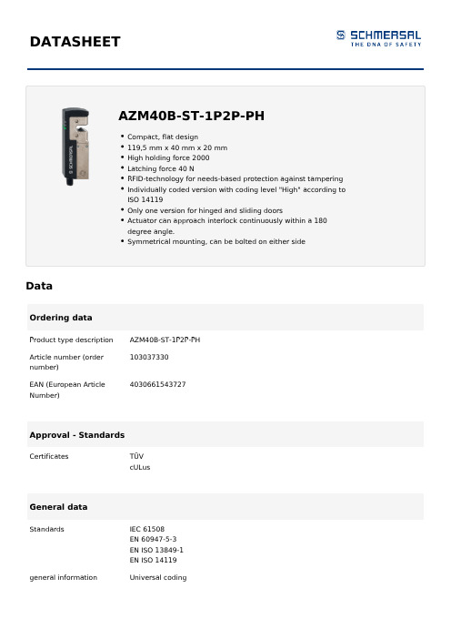
DATASHEETDataOrdering dataProduct type description AZM40B-ST-1P2P-PH103037330Article number (ordernumber)4030661543727 EAN (European ArticleNumber)Approval - StandardsCertificates TÜVcULusGeneral dataStandards IEC 61508EN 60947-5-3EN ISO 13849-1EN ISO 14119 general information Universal codingCoding level according toLowISO 14119Active principle RFIDEnclosure material Glass-fibre, reinforced thermoplastic and light-alloy diecast Gross weight270 g4,000 msTime to readiness,maximumReaction time, maximum100 msDuration of risk, maximum200 ms1.5 msResponse time safetyoutputs in case ofswitch-off by safetyinputs, maximumGeneral data - FeaturesActuator monitored YesLatching YesManual release YesShort circuit detection YesShort-circuit recognition YesSeries-wiring YesSafety functions YesYesIntegral SystemDiagnostics, statusNumber of safety contacts2Safety appraisalStandards IEC 61508EN ISO 13849-1Safety appraisal - InterlockingPerformance level, up to eControl category4PFH-value 1.10 x 10⁻⁹ /hPFD value8.90 x 10⁻⁵Safety Integrity Level3(SIL), suitable forapplications inMission Time20 Year(s)Mechanical dataInterlocking principle bistableMechanical life, minimum200,000 Operations2,000 NClamping force inaccordance withISO14119 Fzh2,600 NClamping force, maximumFmaxLatching force40 N0.5 m/sActuating speed,maximumType of the fixing screws DESIGN_MOUNTING_SCREWS11111111111111111112Mechanical data - Switching distances according IEC 60947-5-31 mmEnsured switch distance"ON" Sao8 mmEnsured switch distance"OFF" SarMechanical data - Connection techniqueTerminal Connector Connector M12, 8-pole, A-codedMechanical data - DimensionsLength of sensor119.5 mmWidth of sensor40 mmHeight of sensor20 mmAmbient conditionsDegree of protection IP66 to EN 60529IP67 to EN 60529+0 °CAmbient temperature,minimum+55 °CAmbient temperature,maximumStorage and transport-40 °Ctemperature, minimum+85 °CStorage and transporttemperature, maximumResistance to vibrations10 … 55 Hz, amplitude 1 mmto EN 60068-2-6Restistance to shock30 g / 11 msProtection rating IIIAmbient conditions - Insulation valueRated insulation voltage U32 VDCi0.8 kVRated impulse withstandvoltage UimpOvervoltage category III3Degree of pollution to VDE0100Electrical dataNo-load supply current I100 mARated operating voltage24 VDC - 15 % / + 10 % (stabilised PELV)Operating current1,200 mARequired rated short-100 Acircuit current to EN60947-5-1Note Cable length and cable section alter the voltage drop depending on the outputcurrentSwitching frequency,0.3 HzmaximumElectrical data - Solenoid controlSwitching thresholds-3 V … 5 V (Low)ELEC_DATA_SWITCHING_THRESHOLDS_MAGNET111111111111111111111Current consumption at24V15 mAClassification ZVEI CB24I,SinkC0Classification ZVEI CB24I, Source C1 C2 C3Electrical data - Fail-safe digital inputsSwitching thresholds−3 V … 5 V (Low)15 V … 30 V (High)Current consumption at24V5 mAClassification ZVEI CB24I,SinkC1Classification ZVEI CB24I, Source C1 C2 C3Electrical data - Fail-safe digital outputsRated operating current(safety outputs)250 mAVersions short-circuit proof, p-typeVoltage drop Ud ,maximum2 VCurrent leakage Ir0.5 mA Voltage, Utilisationcategory DC1224 VDCCurrent, Utilisationcategory DC120.25 AVoltage, Utilisationcategory DC1324 VDCCurrent, Utilisationcategory DC130.25 AClassification ZVEI CB24I,SourceC2Classification ZVEI CB24I, Sink C1 C2Electrical data - Diagnostic output Versions short-circuit proof, p-typeVoltage drop Ud ,maximum2 VVoltage, Utilisationcategory DC1224 VDCCurrent, Utilisationcategory DC120.05 AVoltage, Utilisationcategory DC1324 VDCCurrent, Utilisationcategory DC130.05 AStatus indicationNote (LED switching conditions display)Operating condition: LED green Error / functional defect: LED red Supply voltage UB: LED greenPin assignmentPIN 1A1 Supply voltage UB PIN 2X1 Safety input 1PIN 3A2 GNDPIN 4Y1 Safety output 1 PIN 5OUT Diagnostic output PIN 6X2 Safety input 2PIN 7Y2 Safety output 2AccessoryRecommendation(actuator)AZM 40-B1Ordering codeProduct type description:AZM40(1)-(2)-ST-1P2P-(3)(1)Z Guard locking monitoredB Actuator monitored(2)without Standard codingI1Individual codingI2Individual coding, re-teaching enabled(3)without Counterbores for countersunk screws (standard) PH Flat enclosure for protruding screwsPicturesProduct picture (catalogue individual photo)ID: kaz40f24| 1.1 MB | .jpg | 352.778 x 866.422 mm - 1000 x 2456 px - 72 dpi| 100.3 kB | .png | 74.083 x 181.681 mm - 210 x 515 px - 72 dpiK.A. Schmersal GmbH & Co. KG, Möddinghofe 30, 42279 WuppertalThe details and data referred to have been carefully checked. Images may diverge from original. Further technical data can be found in the manual. Technical amendments and errors possible.Generated on: 17/08/2021, 16:36。
不合格品控制程序48701
祥天智能科技不合格品控制程序年月曰版核准:1目的规各种不合格品处理,避免不合格品误用,使不合格品受控。
2围凡本公司的原材料、在产品、半成品、成品的不合格品处理。
3 权责3.1各单位:发现不合格品,开立不合格品处理单。
3.2品保部:原因分析及处置方式判定。
3.3生管、采购:处理退修或退货品,针对报废品进行扣款处理,允收工件的核准。
3.4业务:负责客诉,对顾客反映的问题进行统计、提交。
3.5仓库:办理物料的退货、入库、出库、存放。
4作业流程图相关单位不合格品控制程序相关文件/记录保保库保品品仓品保管品生标示隔离原因分析检验允粒扣款、补料复验Y Y入库/流入下一工序不合格品处理单不合格品处理单人库验收单5程序说明5. 1不合格品的来源5.1.1进料检验时发现5.1.2外购进厂检验时发现5. 1.3制程加工时发现5. 1.4成品检验时发现5. 1.5客诉5.2不合格品的识别5.2. 1在进料、外购、成品检验时,由品保部派出质检员根据相应产品的《检验标准书》中的各项检验规对其进行检验及判定,出现不合格品时由质检员填写《不合格品处理单》,最终交由品保部负责人进行后续处理。
5.2.2制程加工过程中,相关部门的操作者根据《制程检验标准书》对相应产品进行检验及判定,出现不合格品时由操作者本人填写《不合格品处理单》,最终交由品保部负责人进行后续处理。
5.2.3客户发现的不合格品,由业务部根据客户在现实使用过程中出现的具体不良状况填写《退修单》,并将不合格品召回,最终交由品保部负责人进行后续处理。
5. 3不合格品的标示、隔离及记录5. 3. 1不合格品发生时,由发现单位将不合格品及《不合格品处理单》交由品保部进行判定处理。
5.3.2品保人员将不合格品使用标签、工业吊牌或油漆笔进行标示,并将不合格品放置指定位置或场所进行统一管理。
5. 3.3品保部将《不合格品处理单》中的相关容进行登记及汇总,以便后续处理。
5. 4不合格品原因分析发现不合格品后,各单位将不合格品及《不合格品处理单》交至品保部,品保部负责人根据实物和不合格单中的情况描述对不合格品进行原因分析,并对不合格品进行判定和处置,最终由厂长复核。
非回流阀VBNF-LBA-G14-Q8商品可靠性数据表说明书

non-return valveVBNF-LBA-G14-Q8Broj artikla: 1927027Opći uvjeti primjeneSupport PortalLista pouzdanosti proizvodaThe information in this "Product reliability data sheet" is based on products being used as intended. This includes complying with all specifications in data sheets, catalogues, user documentation and the general operating conditions. The user alone is responsible for determining whether a product is suitable for a particular application.Svojstvo VrijednostWell-tried component1)YesService-life value B102)23 Mio cyclesFault exclusion Spontaneous change in initial switching position (without input signal).For check valves only with applied pressure at port 2.Spontaneous opening of the manual exhaust function in pressurisedand depressurised condition.Vibration resistance Transport application test with severity level 2 in accordance withFN942017-4 and EN 60068-2-6Shock resistance Shock test with severity level 2 in accordance with FN 942017-5 and EN60068-2-271)The product is a well-tried product for a safety-related application according to ISO 13849-1. The relevant basic and well-tried safety principles according ISO 13849-2 for this product are fulfilled. The suitability of the product for a preciseapplication must be verified and confirmed by the user.2)The ascertainment of characteristic service life values is generally based on the ISO 19973 "Pneumatic fluid power - Assessmentof component reliability by testing".15.12.2023. – Pridržano pravo promjena - Festo SE & Co. KG。
质量保证等级及执行标准说明

质量等级
执行标准
质量要求说明
质量补充要求说明
B
GJB597A-1996《半导体集成电路总规范》
1.符合GJB597A-1996规定,列入质量认证合格产品目录(QPL)的B级产品。
2.符合GJB597-1996规定,按B级质量级别规定要求进行管理、生产、筛选和试验控制的产品。
增加技术协议和用户要求
Ⅰ
SJ331-83半导体集成电路技术条件
符合SJ331-83半导体集成电路技术条件规定的产品。
ⅠA
Ⅱ
K1
GJB2438A-2002《混合集成电路总规范》《航天专项工程电子元器件标准要求》
符合GJB2438A-2002规定,按H级质量级别规定要求进行管理、生产、筛选和试验控制的产品。
符合航天专项工程电子元器件标准要求
H+
GJB2438A-2002《混合集成电路总规范》LMS111-2005 《混合集成电路技术条件》
符合航天专项工程电子元器件可靠性增长标准要求gqzj840615电子元器件七专技术条件符合qzj840615电子元器件七专技术条件的产品gqzj840615电子元器件七专技术条件符合qzj840615电子元器件七专技术条件的产品增加技术协议和用户要求hgjb2438a2002混合集成电路总规范符合gjb2438a2002规定按h级质量级别规定要求进行管理生产筛选和试验控制的产品
符合GJB2438A-2002 H级质量级别规定要求进行管理、生产、筛选和试验控制的产品。
符合航天专项工程电子元器件可靠性增长标准要求
G
QZJ840616电子元器件“七专”技术条件
符合QZJ840616电子元器件“七专”技术条件的产品。
ABBsacef2智能断路器铭牌说明

ABBsacef2智能断路器铭牌说明断路器型号含义例:第一单元代表产品名称,用下列字母表示:S少油断路器;D多油断路器;K空气断路器;L六氟化硫断路器;Z真空断路器;Q产气断路器;C磁吹断路器.利用固体绝缘材料在电弧作用下分解并产生气体来灭弧的断路器,称为产气断路器。
靠电磁吹弧,利用狭缝灭弧原理将电弧吹入狭缝中冷却灭弧的断路器称为磁吹断路器。
第二单元代表安装场所,用下列字母表示:N户内式;W户外式第三单元代表设计序号,用数字表示。
第四单元代表额定电压(千伏)。
第五单元代表补充工作特性,用字母表示;G改进型;F分项操作;第六单元代表额定电流第七单元代表额定断流容量(兆伏安)技术参数1.额定电压高压断路器所在系统的最高电压,额定电压指的是线电压,电压等级有10、20、35、60、110、220、330、500千伏各级。
额定电压不仅决定了断路器的绝缘要求,而且在相当程度上决定了断路器的总体尺寸和灭弧条件。
2.额定绝缘水平用雷电冲击电压(Up)来表示,操作冲击电压(Us)和工频电压(Ud)的额定耐受电压值应根据Up选择同一水平值。
绝缘水平有对地、相间和断路器断口三个值。
主要考虑断路器设备接受快波前和缓波前过电压作用的程度、系统中性点接地方式和过电压限制装置的型式。
3.额定电流在规定的使用和性能条件下能持续通过的电流有效值。
4.额定短时耐受电流断路器在合闸状态下能够承载的电流有效值。
断路器的额定短时耐受电流等于其额定断路开断电流。
5.额定短路持续时间断路器设备在合闸状态下能够承载的短时耐受电流的时间间隔。
350~800kV为2s252~363kV为3S126kV及以下为4S6.额定峰值耐受电流在规定的使用和性能条件下,断路器设备在合闸状态下能够承载的额定短时耐受电流第一个大半波电流峰值。
额定峰值耐受电流等于额定短路关合电流,等于2.5倍额定短时耐受电流。
7.额定短路开断电流额定短路开断电流是在规定的使用和性能条件下,断路器能开断的最大短路电流。
- 1、下载文档前请自行甄别文档内容的完整性,平台不提供额外的编辑、内容补充、找答案等附加服务。
- 2、"仅部分预览"的文档,不可在线预览部分如存在完整性等问题,可反馈申请退款(可完整预览的文档不适用该条件!)。
- 3、如文档侵犯您的权益,请联系客服反馈,我们会尽快为您处理(人工客服工作时间:9:00-18:30)。
东 莞 弘 擎 电 子 材 料 科 技 有 限 公 司
DONG GUAN HONG QING ELECTRONIC MSTAR TECHNOLOGY LTD
表单编号:FM-QA
核准: 审核: 制表:
品保系统
IPQC 工作职责文件编号:WIN-QA-002FQC 工作职责文件编号:WIN-QA-001IQC 工作职责文件编号:WIN-QA-003
QE 工作职责
文件编号:WIN-QA-004IQC
IPQC FQC QE 仪校进料检验报告表單編號:FM-QA-022
IPQC 巡检记录表表單編號:FM-QA-025出貨檢驗报告表單編號:FM-QA-028抽样检验作业办法文件编号:WIN-QA-008
首件確認報告表單編號:
抽样检验作业办法文件编号:WIN-QA-008成品检验标准书文件编号:WIN-QA-014仪器设备校正管制一览表文件編號:F M -Q A -008
高温老化箱作业指导书文件編號:F M -Q A -
离型力作业指导书文件編號:W I N -Q A -011
協力廠商評鑒作業方法文件編號:
品質异常联络单表單編號:F M -Q A -024
进料检验记录表表單編號:F M -Q A -023
巡檢记录日報表表單編號:F M -Q A -026
品质异常联络单表單編號:F M -Q A -024
品质异常联络单表單編號:F M -Q A -024
内部校验报告文件編號:F M -Q A -007
剥离力测试报告表單編號:F M -Q A -040
合格供應商名冊表單編號:
出货检验记录表表單編號:F M -Q A -029
品质控制流程图文件编号:F M -Q A -003
检验控制程序文件编号:QP11
检验控制程序文件编号:QP11检验控制程序文件编号:QP11纠正和预防措施控制程序文件编号:Q P 01
不合格品控制程序文件编号:Q P 12
检验控制程序文件编号:QP11儀器量具管制程序
文件编号:
仪器设备年度检验计划
文件编号:仪器设备履历表文件編號:F M -Q A -005
仪器设备校验记录表文件編號:F M -Q A -006
千分尺作业指导书號:W I N -Q A -010。
