ER腐蚀速率探头安装说明书及计算方法
管道腐蚀速率计算方法

管道腐蚀速率计算方法一。
管道腐蚀,这可是个大问题!就像身体里的隐疾,要是不及时发现和处理,后果不堪设想。
那怎么算出这腐蚀的速度呢?1.1 直接测量法。
这就好比是“眼见为实”,咱直接去量一量管道被腐蚀掉的那部分厚度。
用专业的工具,在不同的时间点测量,然后一对比,就能算出腐蚀掉了多少。
比如说,一开始管道壁厚 10 毫米,过了一段时间变成 8 毫米了,这差值除以时间,就是腐蚀速率啦。
1.2 失重法。
把一小段管道样品放在特定的环境里,等它腐蚀一段时间后,称一称重量。
原来多重,现在多重,这少掉的重量就是被腐蚀掉的部分。
再根据时间一算,腐蚀速率就出来了。
这就像“秋后算账”,清清楚楚明明白白。
二。
除了上面这些直接的办法,还有一些间接的招儿。
2.1 电化学方法。
这就有点高科技啦,通过测量管道的电化学参数,像电流、电位啥的,来推算腐蚀速率。
就好像通过“蛛丝马迹”来寻找真相。
2.2 电阻法。
管道的电阻会随着腐蚀而变化,咱就监测这电阻的变化,从而算出腐蚀的快慢。
这就像是“顺藤摸瓜”,找到问题的关键。
2.3 超声波检测法。
用超声波在管道里“溜达”一圈,根据反射回来的信号,就能知道管道的情况,进而算出腐蚀速率。
这简直是“火眼金睛”,啥都逃不过。
三。
不管用啥方法,都得小心谨慎,就像“差之毫厘,谬以千里”。
3.1 测量要精准。
工具得选好,操作得规范,稍有差错,那结果可就不准了。
3.2 环境要考虑。
不同的环境,腐蚀的速度可不一样。
温度、湿度、介质,都得考虑周全,不然就是“盲人摸象”,只看到了一部分。
算管道腐蚀速率,得有耐心,有细心,才能把这“看不见的敌人”给摸清楚,保护好咱们的管道。
腐蚀速率如何计算
腐蚀速率如何计算腐蚀速率如何计算金属材料的腐蚀速度常用金属腐蚀速度的重要指标、深度指标和电流指标表示。
金属腐蚀速度表示法是在要评价的土壤中埋设金属材料试样,经过一定时间后,测试出试样的重量变化或深度变化或电流变化,以此来评价土壤腐蚀性。
重量指标就是把金属因腐蚀而发生的重量变化,换算成相当于单位金属面积与单位时间内的重量变化的数值。
它又分为失重法和增重法两种。
用公式表示为:式中v-—失重时的腐蚀速度,克/米2.小时;v+—增重时的腐蚀速度,克/米2.小时;Wo-—金属的初始重量,克;W1—消除了腐蚀产物后金属的重量,克;W2—带有腐蚀产物的金属的重量,克;S—金属的面积,米2;T—腐蚀进行的时间,小时。
金属腐蚀速度的深度指标是把金属的厚度因腐蚀而减少的量,以线量单位表示,并换算成相当于单位时间的数值。
用公式表示为:式中vL—腐蚀的深度指标,毫米/年;p—金属的密度,克/厘米3。
金属腐蚀速度的电流指标是以金属电化学腐蚀过程的阳极电流密度的大小来衡量金属的电化学腐蚀速度的程度。
可由法拉第(Faraday)定律把电流指标和重量指标联系起来。
可用公式表示为:式中ia—腐蚀的电流指标,即阳极电流密度,安培/厘米2;A——原子量;N——化合价;列举几个常用的腐蚀速率计算方法:1、失重法失重法直接表示由于腐蚀而损失的材料重量,其过程为:对预先制备的试样测量尺寸,净准确称重后置于腐蚀介质中,实验结束后取出,清除产物后清洗、干燥、再称重。
试样的失重直接表征材料的腐蚀程度。
其腐蚀速率的计算方法:通常采用单位时间内单位面积上的重量变化表征平均腐蚀速率g*(m^-2)*(h^-1)。
v=(w0-w1)/(At);其中,W0:试样原始重量(g);w1:试样清除产物后的重量(g);A:试样面积(m^2);t:试验周期(h)但是这种表征方式仍然不能表示出浮士德损耗深度,为此可将腐蚀速度换算成单位时间内的平均腐蚀深度(如:mm/a),其换算关系为:B=(1/ρ)*v*[(365*24*10)/(100*100)]=8.76*v/ρ=8.76*(w0-w1)/(ρ*A*t)B:腐蚀速率(mm/a)v:按重量计算的腐蚀失重速度(g*(m^-2)*(h^-1)。
VOLU-probe 2 方形管探头产品说明书

INSTALLATION PROCEDUREWARRANTYAir Monitor Corporation (hereinafter referred to as "Seller") warrants that at the time of shipment, products sold pursuant to this contract will be free from defects in materials and workmanship, and will conform to the specifications furnished or approved in writing by Seller. No warranty is given that delivered products will conform to catalog sheets, data sheets, and the like, which are subject to change without notice.Seller will repair or replace, at its option, any products listed under this warranty which is returned freight pre-paid to Seller and within the earlier of two (2) years after start-up or twenty-seven (27) months after shipment,prove upon test and examination by Seller to be defective within the terms of this warranty. The warranty period for any item repaired or replaced shall be for the time remaining on the warranty period for the original components.Purchaser shall notify Seller in writing of such defect within sixty (60) days of discovery of the defect.This warranty does not extend to any product sold by Seller which has been the subject of misuse, neglect,accident, damage or malfunction caused by interconnection with equipment manufactured by others, improper installation or storage, or used in violation of instructions furnished by Seller, nor does it extend to any product which has been repaired or altered by persons not expressly approved by Seller. Nor does Seller warrant equipment against normal deterioration due to environment; nor items such as thermocouples, electrodes, and similar items subject to wear or burnout through usage. Adjustments for items or equipment not manufactured by Seller shall be made to the extent of any warranty of the manufacturer or supplier thereof. Seller shall not be liable for any special or consequential damages or for loss of damage directly or indirectly arising from the use of the products. Seller's warranty shall be limited to replacement of defective equipment and shall not include field removal and installation expenses.The warranty set forth above is in lieu of all other warranties either express or implied and constitutes the full extent of Air Monitor Corporation's liability to the customer, or any other party for breach of warranty. THERE ARE NO EXPRESS WARRANTIES EXCEPT AS SET FORTH HEREIN. THERE ARE NO IMPLIED WARRANTIES OF MERCHANTABILITY OR FITNESS FOR ANY PARTICULAR PURPOSE, WHICH ARE PARTICULARLY DISCLAIMED.INSPECTION & HANDLING .VOLU-probe/2 should be carefully inspected for damage prior to installation. Report damage to your Freight Department,or contact the delivery carrier.Almost any means of handling can be utilized depending on the length and weight of the station. Stations may be handled while in any position. However, it is important not to drop or mishandle a station such that damage isdone to the probes, signal connection fittings, or flanges.ORIENTATION OF PROBES.Install VOLU-probes with sensing holes facing airflow.INSTALLING VOLU-probes.To achieve published performance standards, the location of VOLU-probes in ductwork must comply with the Minimum Requirements for Installation (Page 6).VOLU-probes must be mounted so that the Total Pressure (T.P.) sensing holes on the probes are at the center of equal areas in the duct. Refer to dimensions A and B in Figure 1:A = inside dimension (I.D.) of the duct wall on which the probes are to be mountedB = dimension A divided by the quantity of probes furnished per locationINSTALLING VOLU-probes (con't).The VOLU-probe/2 is equipped with integral mounting brackets. See Figure 2 below. Brackets are predrilled so that they may be used as templates for drilling mounted holes in ducts.Figure 2FASTENERS.VOLU-probe mounting brackets are predrilled for 1/4" mounting fasteners. Air Monitor recommends Type AB 1/4" thread-forming tapping screws [use a No. 4 (0.209) drill for pilot hole]. If bolts are desired, Air Monitor recommends the use of 1/4-20 bolts, nuts, and lock washers (or flat washers and lock nuts). Fasteners should be zinc coated carbon steel, or better.DIMENSIONAL SPECIFICATIONS.Figure 3INTERCONNECTING TUBING.Interconnecting tubing and fitting makeup is to be 1/4". If rigid tubing is required, the fittings at the probes and for the interconnecting tubing will be compression fittings. If flexible tubing is required, all connection fittings will be brass or plastic barbed type. Refer to Section A-A for typical tubing configurations.Caution:After interconnection tubing and fitting are completed, signal lines should be leak tested prior to operation.SIGNAL TUBING.Signal tubing for total and static pressure take-off connections may be 1/4" O.D. if the distance from the measuring device to the transmitter is 200' or less.AIRBORNE CONTAMINANTS .The levels of air filtration and cleanliness associated with commercial HVAC Systems, whether supply/return/exhaust/outside air, are satisfactory for operation of the VOLU-probe. Industrial applications containing airborne contaminants may require periodic manual or automatic cleaning using compressed air applied to the signal fittings, and/or removal from the duct or stack for physical cleaning.MINIMUM REQUIREMENTS FOR INSTALLATION .Note: VOLU-probe locations shown are NOT ideal . They indicate the minimum clearance required from air turbulence producing sources. Wherever possible, the VOLU-probe should be installed where greater runs of straight duct (or clearances) than shown exist.()Rectangular Duct: x = Circular Duct:x = Duct Diameter2 H x WH +W ≤ ≤1050 Hopper Avenue • Santa Rosa, CA 95403 • 707-544-2706 CUSTOMER SERVICE. Air Monitor Corporation provides in-house technical support for all our products:Monday through Friday, 7 am to 5 pm (pst)Phone: 707-544-2706 or 1-800-AIRFLOW / Fax: 707-526-2825If after contacting the Customer Service Department it is determined that equipment will require return to Air Monitor Corporation for further repair, a Return Authorization number will be issued. A Confirmation of Return Authorization with shipping instructions will be sent via facsimile or e-mail. Equipment to be returned to Air Monitor should be returned in its original shipping container if possible. If this is not possible, ensure equipment is packaged sufficiently to protect it during shipment.Caution: All damage occurring during transit is the Customer’s responsibility .List the Return Authorization (R/A) number on the packing list and clearly mark this number on the outside of each shipping container. Costs associated with the return of equipment to Air Monitor Corporation are the customer’s responsibility regardless whether the repair/return is under warranty. Once the Customer Service Department determines that the equipment repair is under warranty, the item will be repaired and returned to the customer at no charge. If the equipment is not under warranty, customer will need to approve a repair quote which will be invoiced along with return shipping charges.INSTALL23A(2/16)。
腐蚀检测技术介绍
系统结构简单,易于维护 可在线拆装,不影响生产 可根据需求选择不同的监 测方法 能获得直观的内腐蚀信息 检测多相流实时腐蚀速率 能获得腐蚀、结垢产物及 沉积物
三层挂片探头
电感探针
电阻探针
气相 油相 水相
气相 油相 水相
谢谢!
3.数据转换器 5.数据记录器
下载端口
2.探针适配器
1..电感探针 4.数据电缆
特点: 1、灵敏度高,响应时间短,响应10mpy的腐蚀速率只需 要0.1小时; 2、与具有类似形状的电阻传感器电阻值为 2~60毫欧,电 感阻抗的数值可达 1~5 欧姆,因此,与采用与 ER 法类似 的 测 量 准 确 度 相 比 , 电 感 阻 抗 法 缩 短 100~2500 倍 。 (262144比1000,响应速率提高256倍) 3、应广泛,电导溶液、非电导溶液、油、气、雾多相环 境,水泥和土壤等。 4 、性能稳定,最高承受压力 41.3MPa , 20mil 厚的探头, 在5mpy的腐蚀环境中可连续使用2年。
目录
1、腐蚀挂片介绍 2、电阻探针介绍 3、Microcor技术介绍 4、旁路式内腐蚀检测系统
Hale Waihona Puke Microcor 技术技术是以测量金属损失为基础的,是 将测试线圈外表面的或合金敏感元件处于特定的相对位置, 并给线圈施加一个恒定的交变电流,使得线圈电感对金属 元件的厚度变化非常敏感,从而能测量出由腐蚀引起的式 样厚度发生的极微小的变化,大大提高检测的灵敏度。
目录
1、腐蚀挂片介绍 2、电阻探针介绍 3、Microcor技术介绍 4、旁路式内腐蚀检测系统
系统设计
旁路式管道内腐蚀监测系统是目前最先进、最能 全面跟踪管道内腐蚀状况的腐蚀监测系统,是中海油 具有自主知识产权的腐蚀监测技术。在被监测管道上 安装一段可在线拆装的与管道材质相同的检测管段是 该系统最为独到的设计,因为任何其他检测方法得到 的数据,都不如拆卸检测管段进行目视检查更为直观 、具体、真实。在检测管段上设有多层腐蚀挂片及电 阻探针等在线监测工具,系统数据因此具有多样性、 可靠性和经济性。通过分析多方位腐蚀监/检测数据, 结合腐蚀、结垢产物及微生物等分析手段,指导防腐 措施的调整,使之达到理想的腐蚀防护效果,延长管 道的使用寿命,保证生产正常、安全地进行。该系统 是目前针对管道尤其是长输管道内腐蚀监/检测最有效 的办法。
资料参考-Honeywell安装讲义

腐蚀变送器的现场安装
• 检查腐蚀变送器和安装附件的准备情况。 • 安装好的支架可以用在分体式SmartCET5000上。安装如 下图所示。请遵循下面的安装步骤: • 1、 将夹子 (5) 安装在支架 (2)上, 将夹子 (5)打开, 滑入传 感器安装部位时夹角弹回。 • 2、 用两个(6)螺丝钉将安全固定支架安装在传感器。 2 6 • 变送器固定在管线上: • 1、 将安装支架 (2)放在导管里。 • 2、 用 U型螺母(1) 垫圈 (3)和螺母 (4) 固定安全支架 (2) 。 • 墙壁安装方式: • 用坚固的纽扣将安全安装支架 (2)安装在墙壁上,用坚固 的纽扣将安全支架 (2)安装在墙壁上。
• •
连接腐蚀变送器和探头的电缆连线
在连线之前,请注意以下内容: • 电力的供给必须与标示牌上的数据一致。 • 在连接设备之前要关掉电源。 • 在连接设备前,将等电位的粘合连接到变送器地 面终端。 遵循以下内容连接SmartCET: • 1. 旋开机架盖; • 2. 将电缆插在 ¾” NPT 电口; • 3. 连接上电源. 看终端作业,如右图所示; • 4. 拧上机架盖。
电极的安装
• 确保氟化橡胶垫圈首先安装在电极上。根据腐蚀率有必要每三个月更 换一次电极。因为电极部分有可能被严重腐蚀或者被损坏。如图3所 示。
图3 电极和氟化橡胶垫圈 • 注意,在操作之前要用酒精将电极擦干净。确保电极的灵敏度。 注意,在操作之前要用酒精将电极擦干净。确保电极的灵敏度。
探头的安装
SmartCET5000安装图
安装过程中存在的风险以及防范措施
• 安装或更换探针时,在探针插入或抽出过程中, 松开图2所示固定密封螺母7的时候,有少量介 质的泄漏,这个过程需要引起注意。根据介质 的危险程度确定现场安装人员是否需要配备安 全防护用具如氧气呼吸罩等,并有作业安全监 护人员监护。 现场安装过程中要使用防爆性工具。以免产生 火花。 电极的安装位置对测量数据和探头使用寿命有 一定的影响。因此安装电极前一定要计算好电 极在管道中所处的位置。
ER 电阻探针指南
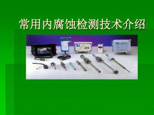
GL003. 1电阻探针(ER ):综合指南 以及 AC & GR 系列探针资料Cormon PER 系列探针和ER 仪器用于测量使用过程中由于腐蚀/侵蚀造成的金属损失。
本产品用于测量被腐蚀样品元件的电阻变化。
这种方法几乎可用于所有环境,可不受工艺性质限制。
如果可能有导沉积物(硫化铁)出现,建议不要将ER 用在酸性环境。
当样品元件的电阻率随温度变化而变化时,一定要使用补偿法。
我们将一个材料相同的被保护元件(称为参考元件)放到与样品元件靠近的位置,同时进行测量。
样品元件和参考元件的测量结果以比值表示,由于两个元件放在相同的温度下测量,所以该测量结果反映的变化就是样品元件的金属损失。
任何两个不同时间的金属损失测量结果都有可能用来计算年损失率,结果通常用毫米/年(MMPY )或毫英寸/年(MPY )表示。
AC 安装形式的环线式探针元件的使用寿命是其厚度的一半,样品元件厚度的选择决定了探针的使用寿命和响应速度。
由元件的半厚度和估算腐蚀速率可以得出大概的使用寿命,例如,一个20thou (mil ,即千分之一英寸,下同)厚的元件在腐蚀速率为10MPY 的环境下可使用1年。
鉴于ER 探针的理论分辨率是整个元件厚度的1/1000,所以一个厚度为20thou 的元件可识别的最小变化是0.00002″。
若腐蚀速率为10MPY ,那么金属每天损失0.00003″(0.01″/365),所以,在腐蚀率为10MPY 的环境下,探针的最快响应时间是2/3天,即16小时。
实际应用起来,响应时间比理论值偏低,所以最好假定响应时间为一天。
在实际应用时,一定要在寿命和性能 之间做一个最好的权衡。
Cormon 的产品代码一般是“F ”为平头式,“T ”为管式,“W ”为环线式探针。
见下面的代码页。
探针安装形式要根据使用环境进行相应改变。
Cormon 序列号是和安装方法相关联的,例如:AC 系列是2″高压插入式,序列号放在产品代码字符串中,位于PER 标识之后:“PER AC……”。
3D TRASAR 腐蚀探测器安装指南说明书
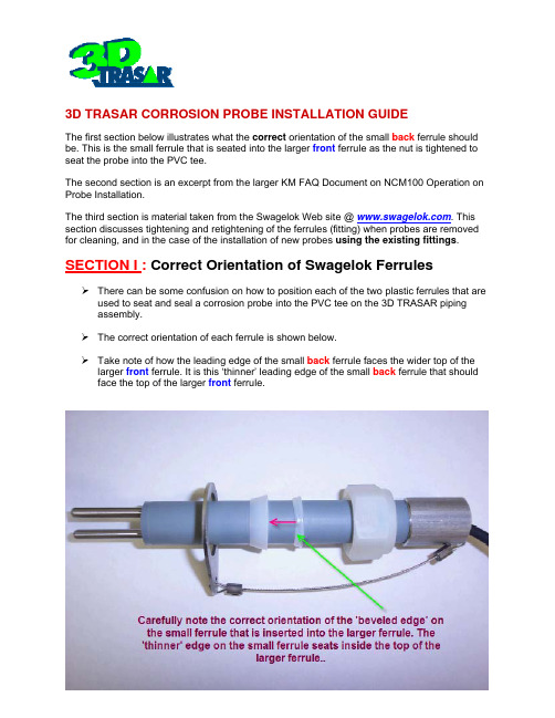
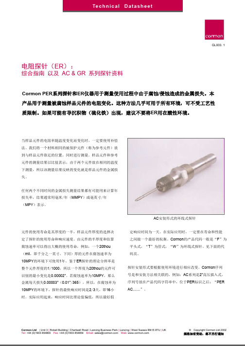
3D TRASAR CORROSION PROBE INSTALLATION GUIDEThe first section below illustrates what the correct orientation of the small back ferrule should be. This is the small ferrule that is seated into the larger front ferrule as the nut is tightened to seat the probe into the PVC tee.The second section is an excerpt from the larger KM FAQ Document on NCM100 Operation on Probe Installation.The third section is material taken from the Swagelok Web site @ . This section discusses tightening and retightening of the ferrules (fitting) when probes are removed for cleaning, and in the case of the installation of new probes using the existing fittings. SECTION I : Correct Orientation of Swagelok FerrulesThere can be some confusion on how to position each of the two plastic ferrules that are used to seat and seal a corrosion probe into the PVC tee on the 3D TRASAR pipingassembly.The correct orientation of each ferrule is shown below.Take note of how the leading edge of the small back ferrule faces the wider top of the larger front ferrule. It is this ‘thinner’ leading edge of the small back ferrule that should face the top of the larger front ferrule.SECTION II : Correct Installation of Corrosion ProbesWhat is the correct installation process for the corrosion probes and restraining straps?There are a few important guidelines to proper installation of the corrosion probes, and the restraining straps which are designed to hold the probes in place. Even though compression fittings are a part of the probe installation, they may not be sufficient to prevent probe ‘blow-out’ should the backpressure increase to a high level.1. PROBE INSTALLATION –As seen below the corrosion probes are installed (inserted) on the horizontal legs of the inlet portion of the water supply piping to the skid, using a white compression fitting ineach case.The water should be flowing toward the tips. The (imaginary) planecontaining the two tips must be parallel to the ground/floor. To avoidcontaminations, DO NOT touch the probe tips with your fingers during installation.The mild steel probe is always installed first (upstream), at then end of the pipe just past the primary flow indicator. The second probe, typically a copper alloy, is always installed in the second (downstream), or last, position, at the end of second horizontal piping leg (as seen below).2. RESTRAINING STRAP INSTALLATION –Note how the one end of the restraining strap with the large hole goes between the hex nut and the threaded portion of the compression fitting. It is NOT installed next to the PVC pipe. The strap will only fit properly IF it is installed as illustrated below.SECTION III : Correct Procedure for Tightening Swagelok Ferrules and Re-Use with New Probe Installation.Screen shots below illustrates typical back ferrule – front ferrule configuration for all Swagelok type fittings.NOTES: Reassembly, Reuse of Swagelok Plastic Fittings, Ferrules1. The plastic Swagelok fitting & ferrules can be reused: after removing a corrosionprobe for inspection, or when installing a new corrosion probe.2. However – inspection and cleaning of the ferrules is recommended in order toensure a watertight seal every time.o Inspect the surfaces of each ferrule for any scratches, gouges, etc.Replace the entire fitting (part number below) if any damage is found.o Carefully wash off and remove any particulate matter sticking to the outside or inside surface of each ferrule. Particulates will scratch anddamage the surfaces when the ferrule is retightened, and could resultin leaks.Swage Fitting, Corrosion Probes 731-P1632.88 $ 20.00。
ER探头及电流环产品说明

MetriCorr腐蚀监控体系及Swainmeter电流环产品说明1.MetriCorr(迈瑞科)腐蚀监控体系MetriCorr(迈瑞科)腐蚀监控体系主要由四部分组成,ER腐蚀探头,ER腐蚀速率仪(ICL-02i),M-report工具,以及无线远传。
其中ER腐蚀探头,ER腐蚀速率仪(ICL-02i)和无线远传需要在现场进行实物安装,M-report工具为数据处理软件。
1.1四部分的作用和关系是什么?ER腐蚀探头填埋在临近管道的土壤中,通过测试桩与管道电连接。
该产品属于电阻探针,带有密封的参比元件,以及一个裸露的试片元件模拟管线的涂层缺陷。
通过测量这两个元件的电阻和简单计算可知裸露试片的实际剩余厚度。
探头可以测量金属损失(腐蚀速率)以及其他电参数,包括直流电势,交流电压,直流电流密度,交流电流密度以及土壤扩散电阻等。
ER腐蚀速率仪(ICL-02i)是一款多功能的双通道数据采集仪器。
一台ER腐蚀速率仪可以同时采集两只探头的数据。
ICL-02i 能够安装在测试站中,通过与埋地的探头相连,进行腐蚀速率以及其他电化学参数的采集。
探头通过该数据记录仪连接管道。
数据记录仪还连接着一个参比电极。
阴保工程师可以在方便的时候读取这些数据。
一旦发生严重的腐蚀,腐蚀速率以及其他电化学数据可以采用专业的分析诊断软件M-Report进行数据处理。
通过分析结果业主可以追溯腐蚀发生的原因,进而采取正确的方式解决问题,排除隐患。
ICL-02-i为双通道数据记录仪,可供记录ER探头的腐蚀监测。
它可以一边记录ER探头的试片减薄,一边记录管道交流电压和直流电势,交直流电流密度和每个试片的扩散/泄露电阻。
ICL-02-i提供适用于任何腐蚀的诊断工具。
ICL-02-i可以安装在标准的测试桩里,监控两个探头。
数据记录周期在很宽的范围内可以选择。
如果是长期监控,每天一两个数据就可以了;如果是要研究腐蚀速率与电气参数的关系,就采样频繁一点。
M-Report工具功能先进,操作简单,用于管理和展示数据。
- 1、下载文档前请自行甄别文档内容的完整性,平台不提供额外的编辑、内容补充、找答案等附加服务。
- 2、"仅部分预览"的文档,不可在线预览部分如存在完整性等问题,可反馈申请退款(可完整预览的文档不适用该条件!)。
- 3、如文档侵犯您的权益,请联系客服反馈,我们会尽快为您处理(人工客服工作时间:9:00-18:30)。
ER腐蚀速率探头
使
用
说
明
书
河南邦信防腐材料有限公司
2019版
ER腐蚀速率探头简介:
河南邦信公司生产的ER腐蚀速率探头用于交直流杂散电流引起的管道腐蚀速率监测以及阴极保护有效性的验证。
可以监/检测:探头试片腐蚀速率、通电电位、极化电位、交流电压、直流电流密度、交流电流密度、防腐层破损点扩散电阻等参数。
ER腐蚀速率探头是一个精密的电子产品,使用一个裸露的试片模拟防腐层缺陷。
该产品安装在临近管道的土壤中,探头试片通过测试桩与管道电连接。
使用配套的数据记录仪测量该探头试片的电阻变化可以得到试片的腐蚀速率(该过程无需开挖、取出试片)。
此外,该数据记录仪还可以测量和记录管道电位、交流电压、电流密度、扩散电阻等参数。
数据记录仪可以安装在测试桩中。
探头试片的理论是多次使用的。
安装之后,只有在腐蚀特别严重试片被完全腐蚀穿透时才需要更换。
数据记录仪的数据可以通过接口导入计算机,也可以使用GSM/GPRS网络无线传输。
技术参数
●标准材质:碳钢(可定制)
●防腐层破损点面积:0.4cm2 1.0cm2 10cm2
●试片标准厚度:100-500μm(可定制)
●电缆长度:6m或12m(最长30m)
●执行标准:ANSI/NACE RP0104-2004
更多图片索取及计算方法请咨询河南邦信防腐材料有限公司技术部腐蚀速度的计算公式:
(W
1-W
2
)×87600
X=───────── mm/a
A·T·D
X──试片腐蚀速率 mm/a
W
1
──试片试前称重 g
W
2
──试验后试片称重 g
87600──计算常数
A ──试片表面积 cm2
T ──试验时间 h
D ──试片材质密度 g/cm3
几种常见金属的重度
腐蚀速度的换算
注:非括号内数值指碳钢材质换算结果;r为金属重度(g/cm3)
ER腐蚀速率探头在地埋燃气管道的施工安装方法
ER腐蚀速率探头在地埋燃气管道的施工安装方法
ER腐蚀速率探头在地埋燃气管道阴极保护后的测试方法
ER腐蚀速率探头在地埋燃气管道阴极保护后的校正方法
ER腐蚀速率探头在地埋PCCP管道的阴极保护施工安装方法
ER腐蚀速率探头在地埋PCCP管道的阴极保护测试桩施工接线方法
ER腐蚀速率探头数据记录仪智能远传施工接线方法。