易德莱斯滚轮架、变位机遥控器、支持变频器调速、 遥控距离
u型变位机参数-概述说明以及解释
u型变位机参数-概述说明以及解释1.引言1.1 概述U型变位机是一种常用的工业设备,用于将物料从一条输送线转移到另一条输送线,实现生产线的自动化作业。
在工业生产中,U型变位机的参数设置对于设备的性能和效率起着至关重要的作用。
本文将重点探讨U 型变位机的参数及其影响因素,并分析其在工业生产中的应用。
通过深入了解U型变位机的工作原理和参数设定,可以帮助工程师和生产管理者更好地优化生产流程,提高生产效率。
1.2文章结构1.2 文章结构本文将首先介绍U型变位机的工作原理,包括其基本原理和运行机制。
接着,我们将详细讨论U型变位机的参数及其影响因素,分析各个参数对机器性能的影响和调整方法。
最后,我们将探讨U型变位机在工业生产中的应用案例,分析其在提高生产效率和优化生产流程中的作用。
通过对U 型变位机参数的研究与分析,我们能够更好地理解和利用这一关键工业装备,为工业生产的发展提供更多可能性和机会。
1.3 目的U型变位机作为一种重要的工业设备,在工业生产中扮演着至关重要的角色。
本文的目的是深入探讨U型变位机的参数及其影响因素,以便更好地了解U型变位机在工业生产中的作用和应用。
通过对U型变位机的工作原理、参数及其影响因素进行详细分析,可以帮助工程师和研究人员更好地设计和优化U型变位机,提高生产效率和产品质量。
同时,本文也旨在展示U型变位机参数的重要性,为未来U型变位机的发展提供参考和指导。
通过本文的研究,希望能够促进U型变位机技术的进步,推动工业生产的发展。
2.正文2.1 U型变位机的工作原理U型变位机是一种用于工业生产中物料输送和定位的设备,其工作原理主要基于传动系统和控制系统的协调运作。
在U型变位机的工作过程中,主要包括以下几个步骤:1. 确定目标位置:首先,通过控制系统设定目标位置,确定物料需要移动到的位置。
2. 启动传动系统:传动系统通过马达或气动设备驱动,将物料从原始位置移动到目标位置。
3. 完成变位操作:在传动系统的作用下,U型变位机实现物料的变位操作,即将物料从一个位置移动到另一个位置。
Mitsubishi Electric 工业机器人 MELFA RV-8CRL 产品介绍说明书

FACTORY AUTOMATIONMITSUBISHI ELECTRICINDUSTRIAL ROBOTMELFA RV-8CRLAllied Automation 800-214-0322Pursuing practical performanceUses an HK motor, the latest servomotor from Mitsubishi Electric. This allows improved torque characteristics, accuracy, and responsiveness while substantially reducing the size and weight. This adds up to much better robot performance and greater compactness.Continuous operation performanceLighter weight and improved heat release translate to improved continuous operation performance.Beltless coaxial drive mechanismA coaxial drive mechanism without belts is used for transmission to each axis (excluding the J4 and J5 axes).Simplification of the structure has improved transmission efficiency and reliability while also improving the ease of maintenance.No backup batteryThe use of the new HK motor eliminates the need for a battery to back up the robot’s internal encoder.This eliminates the cost and effort of regularreplacement as well as the risk of losing origin coordinates due to battery failure.A signal wire and air piping that can be used for gripper control, etc., are built in from the base to the forearm. Both ends of the signal wire haveuniversal D-sub connectors for use in various applications.Highest-in-class load capacityFeaturing a highest-in-class maximum load capacity of 8 kg, these robots boast a lighter-weight structure and reduced unit weight thanks to their simplified drive system and optimized arm structure, resulting in enhanced load capacity.Largest-in-class effective working areaOffers highest-in-class maximum reach radius of 931 mm. The use of a no-offset lower arm structure eliminating the J2-axis joint offset minimizes the interference region in the minimum turning radius and provides the largest-in-class effective working area.Standard IP65 supportComes standard with environmental resistance features allowing installation in plants and equipment where dust or oil mist is present.Can be used in oil mist environmentsJ6-axis motorJ3-axismotor J2-axismotorJ1-axismotor Slim & Compact Robot Offering a High Level of Utility and DesignSlim & compactA smooth, curved design complements the slim arm and compact joints. The external design is marked by minimalist, functional design.*Installation pitch:□160 mm (same as RV-4FR and 20% less than RV-7FR)Protrusionless structureIn addition to a slim, compact exterior and small robot base, its structure features minimal protrusions to the front, back, and sides, resulting in reduced interference with surroundings when the robot operates. This makes it suited to integration with automation cells and manufacturing equipment.1High-performance Controller Makes MELFA More IntelligentSafety monitoring functionWe will prepare a safety function compliant with international standards that simplifies risk assessments.Safety I/OExtends redundant safety I/O to 8 inputs and 4 outputs. Enablesdevelopment of various safety systems.Safety logic editingSimplifies development and operation of safety systems with safety logic editing.●Program editing and debugging ●Simulation function ●3D viewer●Monitoring function●Melfa RXM.ocx communication middlewareTrackingRobot tracks workpiece on conveyor, allowing transfer, alignment, and assembly without stopping conveyor.Additional axis controlBuild user mechanism controlling additional axes simultaneously with robot such as robot drive axis or turntable or separate from robot such as loader or positioning device. Control up to 8 axes. Our MELSERVO (MR-J4-B)servomotor can be used with additional axes.Robot mechanism thermal compensation functionMeasures the temperature of the robot arm and automatically corrects errors arising from thermal expansion of the arm.Callibration assistance functionAutomated calibration translates to simplification of installation of two-dimensional vision sensor and improvement of operational accuracy.Coordinated control of additional axesLinks robot and travel base for high-accuracy processing and assembly at specific speed.Also supports optional MELFA SmartPlusfunctional enhancement *1Comes standard with tracking and additional axis control PC software supporting everything from robot system designto installation, debugging, operation, and maintenance●Vision sensor configuration tool allows easy calibration of robot and camera ●Easy connection of robot and camera via Ethernet ●Easy control via robot program vision control commandSimultaneous controlmechanismsMechanism 1Mechanism 2Mechanism 3Up to 3Additional axesVision sensorSupports multiple conveyors simultaneously (up to 8)*1: Coming soonRobot controllerRobotLaser scannerTeaching boxRT ToolBox3Emergency stopArea sensorLamp2SpecificationsMechanical interfaceInternal wiring/pipingWiring/pipingInstallation dimensionsExternal dimensions/operating rangeMain Specifications15-pin D-sub AWG#24 (0.2mm ) ×15φ6 air joint (2)φ6 hose (2)Black Green Red Brown Yellow OrangeBlue Purple Gray Pink Light blue (Black)/Yellow (Black)/White (Black)/Blue 123456789101112131415123456789101112131415①②Baseφ6 air joint ①Tool wiring connector (15-pin D-sub)Tool wiring connector (15-pin D-sub)φ6 air joint ②Air pipe (2)φ6 air joint ①BaseUpper armForearmView A15-pin D-subForearmφ6 air joint ②Tool wiring (15)Tool wiring connectorRz25R z 25(Installation reference plane)(I n s t a l l a t i o n r e f e r e n c e p l a n e )1908080(160)978080(160)9797φ40h 8φ20H 7D6P .C.D .φ31.545°4-M5 thread depth 8φ5H7D84-φ9 installation hole*1: The wall mounting specifications are special specifications that restrict the operating range of the J1 axis.*2: “Maximum load capacity” is the maximum weight that can be loaded under the limitation of a mechanical interface having a downward attitude (within ±10° of the vertical position).View BP point operating areaP pointR 930.5-170°+170°R 219.315071R 150930.5930.51320.5244.4634.4930.585470390450100R 930.5+110°-110°Control point (R point)P point operating areaP point Downward limit of wristR 219.3102028020A71BWrist's downward singularity boundarySpace for the cable connectionMinimum: 310250256White 3External dimensions*2: Power supply voltage variability is within 10%.*3: Power capacity is recommended value.Note that power capacity does not include making current when turning on. Power capacity is an estimate.*4: Grounding work is to be performed by the customer.*5: Recommended USB cable (USB Type A, USB Mini-B Type): MR-J3USBCBL3M (Mitsubishi Electric), GT09-C30USB-5P (Mitsubishi Electric System & Service)*6: Mode select switch is to be provided by the customer.Controller specificationsStand-alone robot controllerRobot controller can be used for centralized control.430(30)30(3.5)37099.59642534045(40)(45)CR800-D4System configurationParallelinput-output interfaceinput-output unitExternal input-output cableCC-Link <Standard devices>GOT Pulse encoderServo Network R56TBR32TBsupport(SmartPlus)Machine cableController protection box<Functional options>Force sensor set MELFA-3D Vision⑨⑥RT ToolBox3 mini RT ToolBox3RT ToolBox3 Pro⑭②Encoder interfaceRobotRobot controller*1: Coming soon5OptionsController optionsFunctional optionsExpanded software functions*1: Coming soon6L (NA )09102ENG-BAll trademarks acknowledged.Printed December 2019HEAD OFFICE: TOKYO BLDG., 2-7-3 MARUNOUCHI,CHIYODA-KU, TOKYO 100-8310, JAPANMitsubishi Electric Corporation Nagoya Works is a factory certified for ISO 14001 (standards for environmental management systems) and ISO 9001(standards forquality assurance management systems)Global Partner. Local Friend.Allied Automation 800-214-0322。
1升降平台车技术规格书
1升降平台车技术规格书1.产品简介集装箱/集装板升降平台车是一种全液压转向、前桥驱动,行车气制动,行驶无级变速的自驱动车辆,该平台车的最大装卸重量为6.8吨,最大升降高度为3.5米,可满足国内机场现有的所有机型底舱集装箱、集装板货物装卸。
2.产品标准2.1 IATA AHM910 《飞机地面支持设备基本要求》2.2 IATA AHM913 《飞机地面支持设备基本安全要求》2.3 ISO6968(1994) 《宽体飞机腹舱集装箱、集装板升降平台车-性能要求》2.4 IATA AHM931 《宽体飞机腹舱集装箱、集装板升降平台车-性能要求》2.5 Q/WGT020-2004 《WG系列集装箱、集装板升降平台车》3.工作条件3.1 海拔高度:≤2000m3.2 环境温度:-40°C~+65°C3.3 风速:≤22m/s注:严寒地区对发动机需提出低温启动配置要求,高海拔地区对发动机动力提出特殊要求4.技术规格4.1 最大提升量:≧6800kg4.2 主平台4.2.1 提升速度:≧14m/min4.2.2 传送速度:≧18m/min4.2.3 最小高度:≧480mm4.2.4 最大高度:≦3600mm4.2.5 挡板内宽:2480mm4.3 桥平台4.3.1 提升速度:≧4m/min4.3.2 传送速度:≧18m/min4.3.3 最小高度:≧1799mm4.3.4 最大高度:≦3550mm4.4 外形尺寸(长×宽×高):≦8620×3700×30404.5 行驶性能4.5.1 最高行驶速度:≦11km/h4.5.2 制动距离(最高时速时):≦4m4.5.3 最小转弯半径:≦8.5m4.5.4 最大转向角:30°4.6 整备重量:≧15000kg4.7 装载量:一次可同时装载集装板(3175×2438)一个,集装箱(LD-3)两个。
双电源转换开关-PC级
利海尔轨道受力推挽机商品说明书
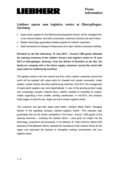
Pressinformation Liebherr opens new logistics centre at Oberopfingen, Germany∙Spare parts supplies for the Earthmoving Equipment division will be managed froma new central location, and other construction machinery divisions are set to follow. ∙Modern technology guarantees reliable supplies for Liebherr customers.∙Ideal connections to transport infrastructure and major Liebherr production facilities.Kirchdorf an der Iller (Germany), 19 June 2015 –Around 1,000 guests attended the opening ceremony of the Liebherr Group's new logistics centre on 19 June 2015 at Oberopfingen, Germany. From the district of Kirchdorf an der Iller, the family-run company will in the future supply customers around the world with spare parts for earthmoving machines.The logistics centre is the new central hub from which Liebherr customers around the world will be supplied with spare parts for wheeled and crawler excavators, wheel loaders, crawler tractors and other earthmoving machines. Until 2013, the management of spare parts supplies was more decentralised. In view of the growing product range and increasingly complex material flows, Liebherr decided to centralise its system, initially organising it from smaller, existing warehouses. In mid-2013, the company finally began to build the new, larger and more modern logistics centre.“Our customer now get their spare parts faster,” explains Martin Barth, managing director of the operating company Liebherr-Logistics GmbH. “This important step guarantees that we will remain competitive in the future.” Around 1,000 guests at the opening ceremony –including the Liebherr family –were given an insight into the technology, proportions and processes. In his address, Dr. Heiko Schmid, district chief executive of the Biberach district, stressed the importance of the Liebherr Group for the region and welcomed the decision to strengthen existing commitments with new logistics centre.Fully automated material flow and maximum supply reliabilityThe new central warehouse has an area of 47,000 m² – about the size of six football pitches – space for about 100,000 different spare parts for the Earthmoving Equipment division. Parts are taken into and out of stock in the automatic warehouse areas - which can be up to 36 m high - by energy-efficient operating machines. The responsible persons at Liebherr-Logistics GmbH employ extremely short throughput times: “Our modern warehouse technology and order picking systems make it possible to ship 1,600 individual orders to many European countries – almost all of them on the day the order is received,” explains Martin Barth. Redundant IT systems, the ability to conduct preventative maintenance work during ongoing operations and modern fire prevention measures guarantee maximum supply reliability.Strategically important location, best transportation connections and future potentialThe location at Oberopfingen was chosen deliberately. Not only is the site directly next to the A7 autobahn, it is also in the immediate neighbourhood of the major production site for Liebherr earthmoving machines at Kirchdorf an der Iller. Other plants from the construction machinery and components divisions in France, Austria and Switzerland are also not far away. “We consi dered, analysed and evaluated various locations for the warehouse,” Martin Barth continues. “In the end, Oberopfingen was the favourite.” In the final expansion phase in a few years time, the site should grow to a total of 360,000 m², or more than 50 football pitches, and hall space will be created to secure the logistics processes for the decades ahead. In the long term, the Liebherr Group is planning to merge the spare parts logistics of other construction machinery divisions in Oberopfingen.Captionsliebherr-logistics-centre-1-300dpi.jpgThe new Liebherr logistics centre at Oberopfingen near Kirchdorf an der Illerliebherr-logistics-centre-2-300dpi.jpgMartin Barth, managing director of Liebherr-Logistics GmbH (right), and logistics manager Kilian Ribheggeliebherr-logistics-centre-3-300dpi.jpgManual warehouse area and shipping at the new Liebherr logistics centre at Oberopfingenliebherr-logistics-centre-4-300dpi.jpgSpare parts are automatically moved on roller conveyors.Contact personKristian KüppersCorporate CommunicationPhone: +49 7351 41-2708E-mail:******************************Published byLiebherr-International Deutschland GmbHBiberach / Riss, Germany。
机械水平移动导轨的驱动力分析

机械水平移动导轨的驱动力分析导轨系统是机械设备中常见的运动部件,它可以实现物体在水平方向上的平稳移动。
机械水平移动导轨的驱动力是实现导轨移动的关键要素,对于导轨系统的性能和运动稳定性具有重要影响。
本文将对机械水平移动导轨的驱动力进行分析和探讨。
一、驱动力的定义和作用机械水平移动导轨的驱动力是指施加在导轨上的力量,用于推动物体在导轨上移动。
驱动力的大小和方向对于导轨的运动速度以及运动方向起着决定性作用。
合理的驱动力设计可以保证导轨系统的平稳运动和精确定位。
二、驱动方式和驱动力来源机械水平移动导轨的驱动方式多种多样,常见的驱动方式包括:1. 轮轴驱动:通过轮轴与导轨直接接触,通过传动装置提供的力矩来推动导轨的运动。
2. 皮带传动:通过皮带与导轨连接,通过皮带传递的张力来实现导轨的移动。
3. 滚珠丝杠传动:通过滚珠丝杠与导轨连接,通过滚珠丝杠传递的转矩来推动导轨的运动。
驱动力的来源主要有两种:1. 电动力:通过电动机产生的转矩和功率,通过不同的传动装置传递给导轨,推动导轨的运动。
2. 气动力:利用气压通过气缸传递给导轨,产生推动力以实现导轨的移动。
三、驱动力的计算方法确定机械水平移动导轨所需的驱动力大小需要考虑多个因素,包括物体的质量、摩擦系数以及系统的惯性等。
以下是常用的计算方法:1. 物体质量计算:根据导轨上所要移动的物体的质量,通过物体的重力和加速度计算物体所受的垂直推力。
2. 摩擦力计算:根据导轨的摩擦系数和物体所受的垂直推力,计算出产生的摩擦力。
3. 惯性力计算:如果物体需要进行加速或减速运动,还需要考虑惯性力的影响,根据物体的质量和加速度计算出惯性力大小。
综合考虑以上因素,可以得到机械水平移动导轨所需的总驱动力大小。
四、驱动力的控制和调节为了实现导轨的平稳运动和精确定位,对驱动力的控制和调节非常重要。
常用的控制和调节方法包括:1. 电子调速:通过电动机的转速控制器,调整电动机的转速和输出功率,从而控制驱动力的大小和方向。
140DDI35300说明

140DDI35300说明140DDI35300详情请访问我的商铺首页 联系人:郑工-0196 联系QQ:2689339198 主营:世界知名品牌的PLC 、DCS 系统备件模块〖⒈〗Allen-Bradley(美国AB)系列产品》〖⒉〗Schneider(施耐德电气)系列产品》〖⒊〗General electric(通用电气)系列产品》〖⒋〗Westinghouse(美国西屋)系列产品》〖⒌〗SIEMENS(西门子系列产品)》〖⒍〗销售ABB Robots. FANUC Robots、Y ASKA WA Robots、KUKA Robots、Mitsubishi Robots、OTC Robots、Panasonic Robots、MOTOMAN Robots。
〖⒎〗estinghouse(西屋):OV A TION 系统、WDPF系统、MAX1000系统备件。
〖⒏〗Invensys Foxboro(福克斯波罗):I/A Series 系统,FBM(现场输入/输出模块)顺序控制、梯形逻辑控制、事故追忆处理、数模转换、输入/输出信号处理、数据通信及处理等。
Invensys Triconex: 冗余容错控制系统、基于三重模件冗余(TMR)结构的最现代化的容错控制器。
〖⒐〗Siemens(西门子):Siemens MOORE,Siemens Simatic C1,Siemens数控系统等。
〖⒑〗Bosch Rexroth(博世力士乐):Indramat,I/O模块,PLC控制器,驱动模块等。
〖⒒〗Motorola(摩托罗拉):MVME 162、MVME 167、MVME1772、MVME177等系列。
联系人:郑工危险本手册以及变频器上带有警示标志的危险是指,如果不遵守有关要求,不采取相应措施,就会造成死亡或严重的人身伤害。
警告本手册以及变频器上带有警示标志的警告是指,如果不遵守有关要求,不采取相应措施,就存在有可能造成死亡或严重人身伤害的潜在危险。
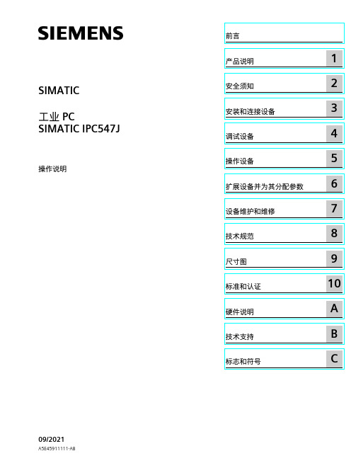
SIMATIC IPC547J SIMATIC 工业 PC SIMATIC IPC547J 操作说明
C
法律资讯
警告提示系统
为了您的人身安全以及避免财产损失,必须注意本手册中的提示。人身安全的提示用一个警告三角表示,仅 与财产损失有关的提示不带警告三角。警告提示根据危险等级由高到低如下表示。
危险 表示如果不采取相应的小心措施,将会导致死亡或者严重的人身伤害。
警告 表示如果不采取相应的小心措施,可能导致死亡或者严重的人身伤害。
Siemens AG Digital Industries Postfach 48 48 90026 NÜRNBERG 德国
A5E45911111-AB Ⓟ 09/2021 本公司保留更改的权利
Copyright © Siemens AG 2021. 保留所有权利
前言
本操作说明的用途 本操作说明包含 SIMATIC IPC547J 安装、电气连接、调试和扩展以及维护和维修设备所需 的全部信息。本操作说明是专为以下具有资质的专业人员编写的: • 装配工 • 调试工程师 • IT 管理员 • 维修与维护人员
SIMATIC IPC547J
SIMATIC 工业 PC SIMATIC IPC547J
操作说明
09/2021
A5E45911111-AB
前言
产品说明
1
安全须知
2
安装和连接设备
3
调试设备
4
操作设备
5
扩展设备并为其分配参数
6
设备维护和维修
7
技术规范
8
尺寸图
9
标准和认证
10
硬件说明
A
技术支持
B
标志和符号
小心 表示如果不采取相应的小心措施,可能导致轻微的人身伤害。
பைடு நூலகம்注意
719遥控器臂架快慢速调节与臂架线性延时调节步骤说
719遥控器臂架快慢速调节与臂架线性延时调节步骤说一、快速调节:1.首先,将机械臂的电源打开,确保电源开关处于正常工作状态。
2.打开719遥控器上的快速调节开关,这通常位于遥控器的上方。
确保开关处于打开状态。
3.将遥控器上的控制杆推到最大位置,观察机械臂是否进行快速的运动。
如果机械臂没有进行快速运动,可尝试调节遥控器上的调速按钮,将调速按钮拨到合适的位置。
4.如果机械臂的运动速度过快或过慢,可以通过遥控器上的速度控制按钮进行微调。
将按钮拨到“+”方向,机械臂的速度会加快;将按钮拨到“-”方向,机械臂的速度会减慢。
5.当调整到满意的快速运动速度后,可以继续进行其他调节。
二、慢速调节:1.将遥控器上的快速调节开关关闭。
2.打开慢速调节开关,这通常位于遥控器的左侧。
3.将遥控器上的控制杆推到最大位置,观察机械臂是否进行慢速的运动。
如果机械臂没有进行慢速运动,可尝试调节遥控器上的调速按钮,将调速按钮拨到合适的位置。
4.如果机械臂的运动速度过快或过慢,可以通过遥控器上的速度控制按钮进行微调。
将按钮拨到“+”方向,机械臂的速度会加快;将按钮拨到“-”方向,机械臂的速度会减慢。
5.当调整到满意的慢速运动速度后,可以继续进行其他调节。
三、线性延时调节:1.将机械臂停止在一个合适的位置。
2.打开719遥控器上的线性延时调节开关,这通常位于遥控器的右侧。
3.根据机械臂需要延时的时间,通过遥控器上的延时时间设置按钮进行调节。
将按钮拨到合适的位置,以达到所需的延时效果。
4.调节完线性延时后,可以将线性延时调节开关关闭,完成整个调节过程。
通过以上步骤,我们可以实现对719遥控器臂架的快速调节、慢速调节以及线性延时调节。
这些功能可以使机械臂的运动更加精准、灵活,适应不同的工作需求。
莱臣斯平移门机 控制板使用说明书

莱臣斯平移门机控制板使用说明书LYC-K33使用说明书请详细阅读LYC-K33慢速型智能型内置平移门控制板是我公司最新开发的产品,采用先进的微电脑控制,比一般的控制系统更稳定,更安全可靠,并有以下显著特点:1、防冲行程设计当门体到达行程,只能按相反方向按键,电机才能动作,防止冲出行程。
2、电机时间保护避免电机在行程失灵时长时间的运转,时间90秒可以调整。
3、自动关门功能时间可从1~240秒调整。
4、电机力度调整可调整电机运行力度。
5、电机遇阻力度调整可调整电机遇阻力度。
6、高保密性LYC-K33型具有遥控功能,遥控灵敏,遥控距离远,抗干扰性强,并采用目前最先进的跳变编解码技术,比现市场上用的传统遥控器(密码数为6561组)更具高的安全和保密性,密码数可达100万组,并不可破解。
7、遥控器键盘自动锁功能自动锁遥控时间为60S,避免了误触的危险。
操作:配制发射器时,用停键来学习,可自动取消该发射器遥控锁键盘功能;其它键学习默认为有自动锁键盘功能。
8、红外防夹功能(用常开型)当门在关门时,有障碍物挡住红外线时,门体会自动停,并反方向运行,防止夹伤人或物体。
9、LED显示故障检测显示信号的输入输出一目了然,方便使用和维修。
技术参数:输入电压:~220V±10%最大输出电流:5A保险丝选用:AC220V5A遥控距离:开阔地>30米安装步骤:1、安装电机。
2、接电调试。
遥控器使用方法:本控制板最多能配120个遥控器,配第121个遥控器时,第一个遥控器作废(即不能使用)。
A、遥控键盘操作:按动遥控器上的方向(关门开门)键可使电机动作,按遥控器上停键,电机停。
B、锁定手动键盘:当按动遥控器上的锁键时,控制盒进入锁定状态(面板上的停指示灯闪动),即只锁定手动按钮和遥控方向键,可按遥控器上停键解锁(面板上的停指示灯停止闪动);在控制盒锁定状态,必须按遥控器上停键解锁后,才能使遥控器上的方向键和控制器上的手动正常使用。
斯莱德滑轨(安徽)有限公司介绍企业发展分析报告

Enterprise Development专业品质权威Analysis Report企业发展分析报告斯莱德滑轨(安徽)有限公司免责声明:本报告通过对该企业公开数据进行分析生成,并不完全代表我方对该企业的意见,如有错误请及时联系;本报告出于对企业发展研究目的产生,仅供参考,在任何情况下,使用本报告所引起的一切后果,我方不承担任何责任:本报告不得用于一切商业用途,如需引用或合作,请与我方联系:斯莱德滑轨(安徽)有限公司1企业发展分析结果1.1 企业发展指数得分企业发展指数得分斯莱德滑轨(安徽)有限公司综合得分说明:企业发展指数根据企业规模、企业创新、企业风险、企业活力四个维度对企业发展情况进行评价。
该企业的综合评价得分需要您得到该公司授权后,我们将协助您分析给出。
1.2 企业画像类别内容行业金属制品业-铸造及其他金属制品制造资质一般纳税人产品服务空1.3 发展历程2工商2.1工商信息2.2工商变更2.3股东结构2.4主要人员2.5分支机构2.6对外投资2.7企业年报2.8股权出质2.9动产抵押2.10司法协助2.11清算2.12注销3投融资3.1融资历史3.2投资事件3.3核心团队3.4企业业务4企业信用4.1企业信用4.2行政许可-工商局4.3行政处罚-信用中国4.4行政处罚-工商局4.5税务评级4.6税务处罚4.7经营异常4.8经营异常-工商局4.9采购不良行为4.10产品抽查4.11产品抽查-工商局4.12欠税公告4.13环保处罚4.14被执行人5司法文书5.1法律诉讼(当事人)5.2法律诉讼(相关人)5.3开庭公告5.4被执行人5.5法院公告5.6破产暂无破产数据6企业资质6.1资质许可6.2人员资质6.3产品许可6.4特殊许可7知识产权7.1商标信息最多显示100条记录,如需更多信息请到企业大数据平台查询7.2专利7.3软件著作权7.4作品著作权7.5网站备案7.6应用APP7.7微信公众号8招标中标8.1政府招标8.2政府中标8.3央企招标8.4央企中标9标准9.1国家标准9.2行业标准9.3团体标准9.4地方标准10成果奖励10.1国家奖励10.2省部奖励10.3社会奖励10.4科技成果11 土地11.1大块土地出让11.2出让公告11.3土地抵押11.4地块公示11.5大企业购地11.6土地出租11.7土地结果11.8土地转让12基金12.1国家自然基金12.2国家自然基金成果12.3国家社科基金13招聘13.1招聘信息感谢阅读:感谢您耐心地阅读这份企业调查分析报告。
Eaton Moeller 系列 Rapid Link 速控器 198868 说明书
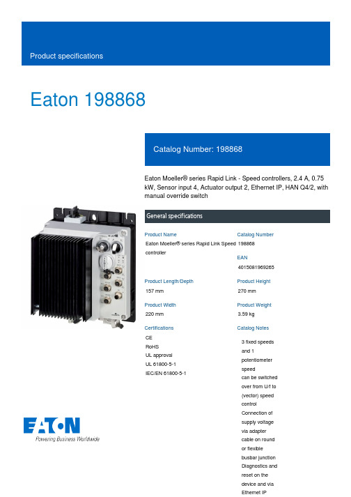
Eaton 198868Eaton Moeller® series Rapid Link - Speed controllers, 2.4 A, 0.75 kW, Sensor input 4, Actuator output 2, Ethernet IP, HAN Q4/2, with manual override switchGeneral specificationsEaton Moeller® series Rapid Link Speed controller1988684015081969265157 mm 270 mm 220 mm 3.59 kg CE RoHS UL approval UL 61800-5-1 IEC/EN 61800-5-1Product NameCatalog NumberEANProduct Length/Depth Product Height Product Width Product Weight Certifications Catalog Notes 3 fixed speeds and 1 potentiometer speedcan be switched over from U/f to (vector) speed control Connection of supply voltage via adapter cable on round or flexible busbar junction Diagnostics and reset on the device and via Ethernet IPParameterization: drivesConnect mobile (App) Parameterization: drivesConnectParameterization: FieldbusParameterization: KeypadIGBT inverterPTC thermistor monitoringSelector switch (Positions: REV - OFF - FWD)Key switch position OFF/RESETKey switch position HANDTwo sensor inputs through M12 sockets (max. 150 mA) for quick stop and interlocked manual operationThermo-click with safe isolationKey switch position AUTO2 Actuator outputsControl unitInternal DC linkPC connectionManual override switch3 fixed speeds1 potentiometer speed IP65NEMA 121st and 2nd environments (according to EN 61800-3)IIISpeed controllerEtherNet/IPC2, C3: depending on the motor cable length, the connected load, and ambient conditions. External radio interference suppression filters (optional) may be necessary.C1: for conducted emissions only2000 VAC voltagePhase-earthed AC supply systems are not permitted. Center-point earthed star network (TN-S network)Vertical15 g, Mechanical, According to IEC/EN 60068-2-27, 11 ms, Half-sinusoidal shock 11 ms, 1000 shocks per shaftResistance: 57 Hz, Amplitude transition frequency on accelerationResistance: According to IEC/EN 60068-2-6Resistance: 10 - 150 Hz, Oscillation frequencyResistance: 6 Hz, Amplitude 0.15 mm Above 1000 m with 1 % performance reduction per 100 m Max. 2000 m-10 °C40 °C-40 °C70 °CFeatures Fitted with:Functions Degree of protectionElectromagnetic compatibility Overvoltage categoryProduct categoryProtocolRadio interference classRated impulse withstand voltage (Uimp) System configuration typeMounting position Shock resistance Vibration AltitudeAmbient operating temperature - min Ambient operating temperature - max Ambient storage temperature - min Ambient storage temperature - max Climatic proofingIn accordance with IEC/EN 50178< 95 %, no condensationCurrent limitationAdjustable, motor, main circuit0.2 - 2.4 A, motor, main circuitDelay time< 10 ms, Off-delay< 10 ms, On-delayEfficiency97 % (η)Input current ILN at 150% overload2.5 ALeakage current at ground IPE - max3.5 mAMains current distortion120 %Mains switch-on frequencyMaximum of one time every 60 secondsMains voltage - min380 VMains voltage - max480 VMains voltage tolerance380 - 480 V (-10 %/+10 %, at 50/60 Hz)Operating modePM and LSPM motorsBLDC motorsSynchronous reluctance motorsU/f controlSensorless vector control (SLV)Output frequency - min0 HzOutput frequency - max500 HzOverload currentAt 40 °CFor 60 s every 600 sOverload current IL at 150% overload3.6 A45 Hz66 Hz0.75 kW400 V AC, 3-phase480 V AC, 3-phase0.1 Hz (Frequency resolution, setpoint value)200 %, IH, max. starting current (High Overload), For 2 seconds every 20 seconds, Power section50/60 Hz8 kHz, 4 - 32 kHz adjustable, fPWM, Power section, Main circuitAC voltagePhase-earthed AC supply systems are not permitted.Center-point earthed star network (TN-S network)1 HP≤ 0.6 A (max. 6 A for 120 ms), Actuator for external motor brakeAdjustable to 100 % (I/Ie), DC - Main circuit10 kAType 1 coordination via the power bus' feeder unit, Main circuit 24 V DC (-15 %/+20 %, external via AS-Interface® plug)Ethernet IP, built inPlug type: HAN Q4/2Specification: S-7.4 (AS-Interface®)Max. total power consumption from AS-Interface® power supply unit (30 V): 250 mANumber of slave addresses: 31 (AS-Interface®)C2 ≤ 5 m, maximum motor cable length C3 ≤ 25 m, maximum motor cable length C1 ≤ 1 m, maximum motor cable lengthMeets the product standard's requirements.Meets the product standard's requirements.Rated frequency - minRated frequency - maxRated operational power at 380/400 V, 50 Hz, 3-phase Rated operational voltageResolutionStarting current - maxSupply frequencySwitching frequencySystem configuration type Assigned motor power at 460/480 V, 60 Hz, 3-phase Braking currentBraking torqueRated conditional short-circuit current (Iq)Short-circuit protection (external output circuits) Rated control voltage (Uc)Communication interfaceConnectionInterfacesCable length10.2.2 Corrosion resistance10.2.3.1 Verification of thermal stability of enclosures10.2.3.2 Verification of resistance of insulating materials tonormal heatMeets the product standard's requirements.Meets the product standard's requirements.Meets the product standard's requirements.Does not apply, since the entire switchgear needs to be evaluated.Does not apply, since the entire switchgear needs to be evaluated.Meets the product standard's requirements.Does not apply, since the entire switchgear needs to be evaluated.Meets the product standard's requirements.Does not apply, since the entire switchgear needs to be evaluated.Does not apply, since the entire switchgear needs to be evaluated.Is the panel builder's responsibility.Is the panel builder's responsibility.Is the panel builder's responsibility.Is the panel builder's responsibility.Is the panel builder's responsibility.The panel builder is responsible for the temperature rise calculation. Eaton will provide heat dissipation data for the devices.Generation change from RA-SP to RASP 4.0Connecting drives to generator suppliesGeneration change RAMO4 to RAMO5Generation change from RA-MO to RAMO 4.0Generation Change RASP4 to RASP5Electromagnetic compatibility (EMC)Configuration to Rockwell PLC for Rapid LinkGeneration Change RA-SP to RASP5Rapid Link 5 - brochureDA-SW-drivesConnect - InstallationshilfeDA-SW-Driver DX-CBL-PC-3M0DA-SW-USB Driver PC Cable DX-CBL-PC-1M5DA-SW-drivesConnect - installation helpDA-SW-drivesConnect USB Driver DX-COM-PCKITDA-SW-USB Driver DX-COM-STICK3-KITDA-SW-drivesConnectMaterial handling applications - airports, warehouses and intra-logisticsProduct Range Catalog Drives EngineeringProduct Range Catalog Drives Engineering-ENDA-DC-00004184.pdfDA-DC-00004514.pdfDA-DC-00003964.pdfDA-DC-00004508.pdfeaton-bus-adapter-rapidlink-speed-controller-dimensions-005.eps eaton-bus-adapter-rapidlink-speed-controller-dimensions-004.eps eaton-bus-adapter-rapidlink-speed-controller-dimensions-003.eps eaton-bus-adapter-rapidlink-speed-controller-dimensions-002.epsETN.RASP5-2420EIP-412R000S1.edzIL034093ZU10.2.3.3 Resist. of insul. mat. to abnormal heat/fire by internalelect. effects10.2.4 Resistance to ultra-violet (UV) radiation10.2.5 Lifting10.2.6 Mechanical impact10.2.7 Inscriptions10.3 Degree of protection of assemblies10.4 Clearances and creepage distances10.5 Protection against electric shock10.6 Incorporation of switching devices and components 10.7 Internal electrical circuits and connections10.8 Connections for external conductors10.9.2 Power-frequency electric strength10.9.3 Impulse withstand voltage10.9.4 Testing of enclosures made of insulating material 10.10 Temperature rise Application notes BrochuresCatalogues Certification reports DrawingseCAD model Installation instructionsEaton Corporation plc Eaton House30 Pembroke Road Dublin 4, Ireland © 2023 Eaton. All rights reserved. Eaton is a registered trademark.All other trademarks areproperty of their respectiveowners./socialmediaIs the panel builder's responsibility. The specifications for the switchgear must be observed.Is the panel builder's responsibility. The specifications for the switchgear must be observed.The device meets the requirements, provided the information in the instruction leaflet (IL) is observed.Rapid Link 5MN034004ENMZ040046_ENMN040003_ENDA-MN-MZ040044ENrasp5_v31.stpramo5_v31.dwg10.11 Short-circuit rating10.12 Electromagnetic compatibility 10.13 Mechanical function Installation videos Manuals and user guidesmCAD model。
卸船机行走夹轮器限位形式改造

大车夹轮器限位形式改造一、功能与原理介绍目前大车夹轮器很多使用的是机械式限位,并且目前更换的备件全部是机械式限位,此种限位是利用触杆与机械行程开关配合使用,当夹轮器打开时,装在制动臂上的机械行程开关向触杆方向移动,使得触杆碰触机械行程开关的拨杆,由此拨动开关,将信号反馈给机房PLC,反应夹轮器已打开;反之当夹轮器闭合时,行程开关远离触杆,行程开关上的拨杆复位,反馈信号切断,机房PLC显示夹轮器已闭合。
装在夹轮器上的机械式限位如图一:图一:1.夹轮器缸体 2.触杆 3.夹轮器制动臂 4.机械行程开关 5.机械行程开关拨杆6.夹轮器螺杆二、存在问题由于机械式行程开关缺乏稳定性,并且必须由触杆触动行程开关拨杆并形成一定角度才起作用,因此在复杂多变的工况下,由于夹轮器有液压控制,长时间工作来回行程不可能完全一致,加之作业过程中,物料落下堆积在夹轮器缸体四周,影响机械式限位的正常动作,使得机械式限位经常性不到位,动作不灵敏,使得大车因夹轮器限位释放故障而无法移动,严重影响生产效率以及工作积极性,间接造成经济损失。
三、解决办法以上问题主要是机械式限位自身存在的缺陷,因此将机械式限位改为感应式接近限位,此种限位形式由电感应接收触头和金属触片组成,通过二者的配合,当夹轮器打开时,位于左侧制动臂上的电感应接收触头会随之向金属触片移动,当触头与触片距离减小到一定程度时(通常为1cm左右),感应限位动作,反馈信号给机房PLC,显示夹轮器打开;反之当夹轮器闭合时,电感应接收触头远离金属触片,使得感应限位恢复,信号停止,机房PLC显示夹轮器闭合。
感应式接近限位稳定性高,实用性强,较适合复杂的工况环境,虽然夹轮器在长时间工作中行程不完全一样,但是只要感应触头与金属触片的距离达到,就会发出信号,因此,不受夹轮器行程影响。
并且可靠性强,由于是感应形式,因此不受任何外力作用,即使物料冲击,只要底座牢固,仍然高效可靠。
改造后的感应式接近限位如图二:图二:1.夹轮器缸体 2.金属触片 3.夹轮器制动臂 4.感应式接近限位底座5.电感应接收触头6.夹轮器螺杆四、效益核算1.通过改造之后有效地保证了大车行走夹轮器的正常使用,提高了设备的稳定性和可靠性,防止了意外故障的发生,使生产更流畅有序的进行。
德瑞斯平移门遥控器学习方法

德瑞斯平移门遥控器学习方法
具体学习步骤:按下电路板上面的(学习键)白色SN2 SEUDY键,等到LED6指示灯灭,立即把手松掉。
连续按两下遥控器任意键两下,听到滴的一声,学习成功。
平移门可以根据以下信息来设置匹配遥控器:
1、打开原遥控器后盖,确定下遥控器芯片型号(在黑色四边形芯片上)和晶振型号(频率)
2、看看车库顶上的汽车品牌。
记住车库顶部汽车外壳上的中英文标记。
把你记录的信息告诉客服,你就会知道如何匹配你的遥控器。
3、同时,您还可以找到滑动门遥控器的制造商进行咨询。
- 1、下载文档前请自行甄别文档内容的完整性,平台不提供额外的编辑、内容补充、找答案等附加服务。
- 2、"仅部分预览"的文档,不可在线预览部分如存在完整性等问题,可反馈申请退款(可完整预览的文档不适用该条件!)。
- 3、如文档侵犯您的权益,请联系客服反馈,我们会尽快为您处理(人工客服工作时间:9:00-18:30)。
成都易德莱斯专注无线控制技术
主要配套滚轮架、变位机
◆遥控距离(空旷直线距离)可达250米;
◆采用全隔离设计和跳频传输技术,确保等离子、氩弧焊、气保焊等工况下无干扰;
◆遥控器支持5组开关量(包括急停)输出和一组模拟量(0-10v电压)输出
◆配置锁定按钮,有效防止误操作
◆遥控器面板采用不锈钢材料,更能适应焊接环境
◆带速度反馈显示功能,遥控器除显示变频器的hz外,还可以显示对应的线速度(单位和对应关系可以自行设定)
◆遥控器手持体积小巧,采用扭子开关和大旋钮速度调节,方便工人单手操作
◆遥控器背部带磁铁,方便工人随时放置在工件表面
◆接收器支持DC/AC 12-24V电源(默认设置),通过跳线可以支持DC 5V
可根据客户要求定制开发各类工业遥控器
我们的优势
1、关键器件全部采用国际品牌,从根本上保证产品质量。
2、我们专注无线控制技术,多年来累积了丰富的经验。
3、我们的产品具有价格优势。
4、定制周期短,一般5-7个工作日。
我们的特点
1、遥控器手持有多种外壳可以选择
2、遥控器有多种输出方式可以选择:485、CAN数字接口、开关量+模拟量输出
3、遥控器可集成驱动板:0-800mA输出、-10v-+10v输出、0-10v输出等,可直接驱
动比例阀以及液压阀等器件。
4、遥控器带反馈输入模块,可直接反馈显示设备的相关状态、参数。
