2SB624中文资料
SBV2钢板规格明细,SBV2日标容器钢板,SBV2钢板切割
SBV2钢板规格明细,SBV2日标容器钢板,SBV2NSR钢板切割
SBV2属于日标容器板,常常被用于锅炉和压力容器的锰钼钢和锰钼镍钢板。
SBV2钢板执行标准:执行日标JIS G3119标准
SBV2钢板库存:#舞阳孙凡#
SBV2钢板化学成分
SBV2钢板碳含量C:≤0.2
SBV2硅含量Si:≤0.13-0.45
SBV2钢板锰含量Mn:≤0.90-1.65
SBV2钢板磷含量P:≤0.035
SBV2钢板硫含量S:≤0.035
SBV2钢板形状、尺寸、重量及允许偏差:SBV2钢板的形状、尺寸、重量及其允许偏差执行JIS G 3193,但是钢板的长度及切边宽度的允许偏差,按除IS G 3193的允许偏差A特别规定的之外。
SBV2广泛应用于石油、化工、电站、锅炉等行业,用于制作反应器、换热器、分离器、球罐、油气罐、液化气罐、锅炉汽包、液化石油气瓶、水电站高压水管、水轮机蜗壳等设备及构件。
SBV2钢板规格明细:
SBV2 10*2500*12000
SBV2 12*2500*12000
SBV2 15*2500*12000
SBV2 16*2500*12000
SBV2 20*2500*12000
SBV2 30*2500*12000
SBV2钢板切割,SBV2钢板数控切割,SBV2钢板等离子切割,SBV2钢板激光切割
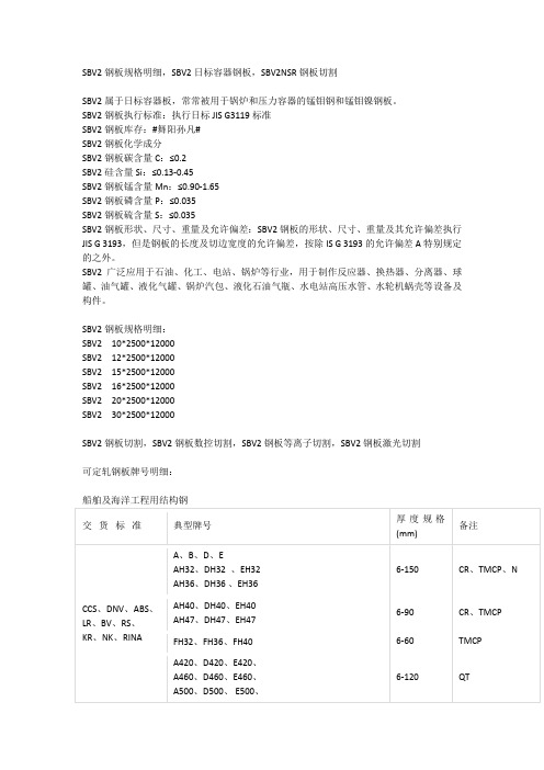
可定轧钢板牌号明细:
船舶及海洋工程用结构钢
耐磨钢
管线用钢
桥梁结构用钢
水电用钢
核电用钢。
M6242B中文资料

CF
1-hour carry
• S1~W~Y10 are time counter register • C0~CF are control register
STDP
PIN CONFIGURATION
STD.P 1 CS0 2 ALE 3 A0 4 A1 5 A2 6 A3 7 RD 8 GND 9
FEATURES
DIRECT MICROPROCESSOR/MICROCONTROLLER BUS CONNECTION
TIME
MONTH DATE YEAR
DAY OF WEEK
23:59:59
12
31
80
7
• 4-bit data bus • 4-bit address bus • READ, WRITE, ALE and CHIP SELECT
INPUTS • Status registers – IRQ and BUSY • Selectable interrupt outputs – 1/64
second, 1 second, 1 minute, 1 hour • Interrupt masking • 32.768 KHz crystal controlled operation
Parameter Power Supply Voltage Input Voltage Output Voltage Storage Temperature
Symbol VDD VI VO TSTG
Condition Ta = 25°C
MSM6242B
Rating
Unit
-0. 3 to 7
V
-0.3 to VDD +0.3
2SD882;中文规格书,Datasheet资料

October 2007Rev 31/82SD882NPN medium power transistorFeatures■High current■Low saturation voltage ■Complement to 2SB772Applications■Voltage regulation ■Relay driver ■Generic switch ■Audio power amplifier ■DC-DC converterDescriptionThe device is a NPN transistor manufactured by using planar technology resulting in rugged high performance devices. The complementary PNP type is 2SB772.Table 1.Device summaryOrder code Marking Package Packing 2SD882D882SOT -32T ubeAbsolute maximum ratings2SD882 1 Absolute maximum ratingsTable 2.Absolute maximum ratingSymbol Parameter Value UnitV CBO Collector-base voltage (I E = 0) 60VV CEO Collector-emitter voltage (I B = 0) 30VV EBO Collector-base voltage (I C = 0) 5VI C Collector current3AI CM Collector peak current (t P < 5ms)6AI B Base current1AI BM Base peak current (t P < 5ms)2AP TOT T otal dissipation at T c = 25°C12.5WT STG Storage temperature-65 to 150°CT J Max. operating junction temperature150°CTable 3.Thermal dataSymbol Parameter Value UnitR thJ-case Thermal resistance junction-case max10°C/W 2/83/82 Electrical characteristics(T CASE = 25°C; unless otherwise specified)Table 4.Electrical characteristicsSymbol ParameterTest conditions Min.Typ.Max.Unit I CES Collector cut-off current(V BE = 0)V CE = 60 V 10µA I CEO Collector cut-off current (I B = 0)V CE = 30 V 100µA I EBOEmitter cut-off current (I C = 0)V EB = 5 V10µAV (BR)CEO(1)Collector-emitter breakdownvoltage (I B = 0 )I C = 10 mA 30VV (BR)CBO Collector-base breakdownvoltage(I E = 0 )I C = 100 µA60VV (BR)EBO Emitter-base breakdownvoltage(I C = 0 )I E = 100 µA5V V CE(sat)(1)Collector-emitter saturationvoltageI C = 1 A I B = 50 mAI C = 2 A I B = 100 mAI C = 3 A I B = 150 mA 0.40.71.1V V V V BE(sat)(1)1.Pulsed duration = 300 ms, duty cycle ≤1.5%.Base-emitter saturation voltage I C = 2 A I B = 100 mA 1.2Vh FE DC current gain I C = 100 mA V CE = 2 V I C = 1 A V CE = 2 V I C = 3 A V CE = 2 V 1008030300f TTransition frequencyI C = 0.1 A V CE = 10 V100MHzcharacteristics (curves) 2.1 Typical4/82SD882Package mechanical data 3 Package mechanical dataIn order to meet environmental requirements, ST offers these devices in ECOPACK®packages. These packages have a Lead-free second level interconnect . The category ofsecond level interconnect is marked on the package and on the inner box label, incompliance with JEDEC Standard JESD97. The maximum ratings related to solderingconditions are also marked on the inner box label. ECOPACK is an ST trademark.ECOPACK specifications are available at: 5/8Package mechanical data2SD8826/82SD882Revision history7/84 Revision historyTable 5.Document revision historyDate RevisionChanges09-Sep-20052Final datasheet. New template 02-Oct-20073Updated mechanical data2SD8828/8Please Read Carefully:Information in this document is provided solely in connection with ST products. STMicroelectronics NV and its subsidiaries (“ST”) reserve the right to make changes, corrections, modifications or improvements, to this document, and the products and services described herein at any time, without notice.All ST products are sold pursuant to ST’s terms and conditions of sale.Purchasers are solely responsible for the choice, selection and use of the ST products and services described herein, and ST assumes no liability whatsoever relating to the choice, selection or use of the ST products and services described herein.No license, express or implied, by estoppel or otherwise, to any intellectual property rights is granted under this document. If any part of this document refers to any third party products or services it shall not be deemed a license grant by ST for the use of such third party products or services, or any intellectual property contained therein or considered as a warranty covering the use in any manner whatsoever of such third party products or services or any intellectual property contained therein.UNLESS O THERWISE SET FO RTH IN ST’S TERMS AND CO NDITIO NS O F SALE ST DISCLAIMS ANY EXPRESS O R IMPLIED WARRANTY WITH RESPECT TO THE USE AND/O R SALE O F ST PRO DUCTS INCLUDING WITHO UT LIMITATIO N IMPLIED WARRANTIES OF MERCHANTABILITY, FITNESS FOR A PARTICULAR PURPOSE (AND THEIR EQUIVALENTS UNDER THE LAWS OF ANY JURISDICTION), OR INFRINGEMENT OF ANY PATENT, COPYRIGHT OR OTHER INTELLECTUAL PROPERTY RIGHT. UNLESS EXPRESSLY APPRO VED IN WRITING BY AN AUTHO RIZED ST REPRESENTATIVE, ST PRO DUCTS ARE NO T RECOMMENDED, AUTHORIZED OR WARRANTED FOR USE IN MILITARY, AIR CRAFT, SPACE, LIFE SAVING, OR LIFE SUSTAINING APPLICATIONS, NOR IN PRODUCTS OR SYSTEMS WHERE FAILURE OR MALFUNCTION MAY RESULT IN PERSONAL INJURY, DEATH, OR SEVERE PROPERTY OR ENVIRONMENTAL DAMAGE. ST PRODUCTS WHICH ARE NOT SPECIFIED AS "AUTOMOTIVE GRADE" MAY ONLY BE USED IN AUTOMOTIVE APPLICATIONS AT USER’S OWN RISK.Resale of ST products with provisions different from the statements and/or technical features set forth in this document shall immediately void any warranty granted by ST for the ST product or service described herein and shall not create or extend in any manner whatsoever, any liability of ST.ST and the ST logo are trademarks or registered trademarks of ST in various countries.Information in this document supersedes and replaces all information previously supplied.The ST logo is a registered trademark of STMicroelectronics. All other names are the property of their respective owners.© 2007 STMicroelectronics - All rights reservedSTMicroelectronics group of companiesAustralia - Belgium - Brazil - Canada - China - Czech Republic - Finland - France - Germany - Hong Kong - India - Israel - Italy - Japan - Malaysia - Malta - Morocco - Singapore - Spain - Sweden - Switzerland - United Kingdom - United States of America分销商库存信息: STM2SD882。
2SB907中文资料
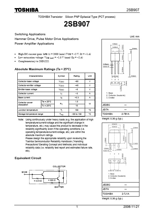
TOSHIBA Transistor Silicon PNP Epitaxial Type (PCT process)2SB907Switching ApplicationsHammer Drive, Pulse Motor Drive Applications Power Amplifier Applications• High DC current gain: h FE (1) = 2000 (min) (V CE = −2 V, I C = −1 A) • Low saturation voltage: V CE (sat) = −1.5 V (max) (I C = −2 A) • Complementary to 2SD1222.Absolute Maximum Ratings (Ta = 25°C)Characteristics Symbol Rating UnitCollector-base voltage V CBO −60 V Collector-emitter voltage V CEO −40 V Emitter-base voltage V EBO −5 V Collector current I C −3 A Base current I B −0.3 A Ta = 25°C 1.0 Collector powerdissipationTc = 25°CP C15WJunction temperature T j 150 °CStorage temperature rangeT stg−55 to 150°CNote: Using continuously under heavy loads (e.g. the application of hightemperature/current/voltage and the significant change in temperature, etc.) may cause this product to decrease in the reliability significantly even if the operating conditions (i.e. operating temperature/current/voltage, etc.) are within the absolute maximum ratings.Please design the appropriate reliability upon reviewing the Toshiba Semiconductor Reliability Handbook (“Handling Precautions”/Derating Concept and Methods) and individualreliability data (i.e. reliability test report and estimated failure rate, etc).Equivalent CircuitUnit: mmJEDEC ― JEITA ―TOSHIBA 2-7B1A Weight: 0.36 g (typ.)JEDEC― JEITA―TOSHIBA 2-7J1AElectrical Characteristics (Ta = 25°C)Markinglead (Pb)-free package orlead (Pb)-free finish.Collector-emitter voltage V CE (V)I C – V CEC o l l e c t o r c u r r e n t I C (A )C o ll e c t o rc u rr e n t I C (A )I C – V CECollector-emitter voltage V CE (V)Col l e c t o r c u r re n t I C (A )Collector-emitter voltage V CE (V)I C – V CED Cc u r re n t g a i n h F Eh FE – I CCollector current I C (A)C o l l e c t o r -e m i t t e r s a t u r a t i on v o l t a g eV C E (sa t ) (V )Collector current I C(A) V CE (sat) – I CCollector current I C (A)V BE (sat) – I CB a s e -e m i t t e r s a t u r a t i o n v o l t a g e V B E (s a t ) (V )−−−−−−−−−−−−−−−−−−0.1−0.3−1−10−3−−−−−−−−−−Collector-emitter voltage V CE (V)Safe Operating AreaC ol le c t o r c u r re n t I C (A )Ambient temperature Ta (°C)P C – TaC o l l e c t o r p ow e rd i s s i p a t i o n PC (W )Base-emitter voltage V BE (V)I C – V BEC o l l e c t o r c u r r e n t I C (A )−−−−−−−−−−−−RESTRICTIONS ON PRODUCT USE20070701-EN •The information contained herein is subject to change without notice.•TOSHIBA is continually working to improve the quality and reliability of its products. Nevertheless, semiconductor devices in general can malfunction or fail due to their inherent electrical sensitivity and vulnerability to physical stress. It is the responsibility of the buyer, when utilizing TOSHIBA products, to comply with the standards of safety in making a safe design for the entire system, and to avoid situations in which a malfunction or failure of such TOSHIBA products could cause loss of human life, bodily injury or damage to property.In developing your designs, please ensure that TOSHIBA products are used within specified operating ranges as set forth in the most recent TOSHIBA products specifications. Also, please keep in mind the precautions and conditions set forth in the “Handling Guide for Semiconductor Devices,” or “TOSHIBA Semiconductor Reliability Handbook” etc.• The TOSHIBA products listed in this document are intended for usage in general electronics applications (computer, personal equipment, office equipment, measuring equipment, industrial robotics, domestic appliances, etc.).These TOSHIBA products are neither intended nor warranted for usage in equipment that requires extraordinarily high quality and/or reliability or a malfunction or failure of which may cause loss of human life or bodily injury (“Unintended Usage”). Unintended Usage include atomic energy control instruments, airplane or spaceship instruments, transportation instruments, traffic signal instruments, combustion control instruments, medical instruments, all types of safety devices, etc.. Unintended Usage of TOSHIBA products listed in his document shall be made at the customer’s own risk.•The products described in this document shall not be used or embedded to any downstream products of which manufacture, use and/or sale are prohibited under any applicable laws and regulations.• The information contained herein is presented only as a guide for the applications of our products. No responsibility is assumed by TOSHIBA for any infringements of patents or other rights of the third parties which may result from its use. No license is granted by implication or otherwise under any patents or other rights of TOSHIBA or the third parties.• Please contact your sales representative for product-by-product details in this document regarding RoHS compatibility. Please use these products in this document in compliance with all applicable laws and regulations that regulate the inclusion or use of controlled substances. Toshiba assumes no liability for damage or losses occurring as a result of noncompliance with applicable laws and regulations.。
肖特基二极管参数表
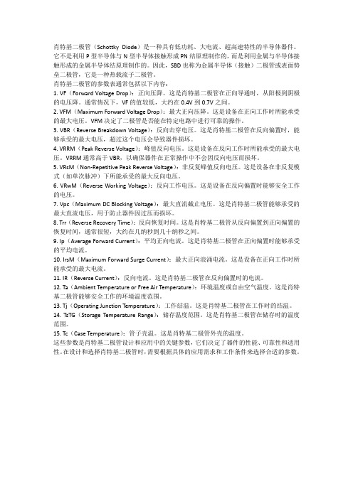
肖特基二极管(Schottky Diode)是一种具有低功耗、大电流、超高速特性的半导体器件。
它不是利用P型半导体与N型半导体接触形成PN结原理制作的,而是利用金属与半导体接触形成的金属半导体结原理制作的。
因此,SBD也称为金属半导体(接触)二极管或表面势垒二极管,它是一种热载流子二极管。
肖特基二极管的参数表通常包括以下内容:1. VF(Forward Voltage Drop):正向压降。
这是肖特基二极管在正向导通时,从阳极到阴极的电压降。
通常情况下,VF的值较低,大约在0.4V到0.7V之间。
2. VFM(Maximum Forward Voltage Drop):最大正向压降。
这是设备在正向工作时所能承受的最大电压。
VFM决定了二极管是否能在特定电路中进行可靠的操作。
3. VBR(Reverse Breakdown Voltage):反向击穿电压。
这是肖特基二极管在反向偏置时,能够承受的最大电压,超过这个电压会导致器件损坏。
4. VRRM(Peak Reverse Voltage):峰值反向电压。
这是设备在反向工作时所能承受的最大电压。
VRRM通常高于VBR,以确保器件在正常操作中不会因反向电压而损坏。
5. VRsM(Non-Repetitive Peak Reverse Voltage):非反复峰值反向电压。
这是设备在非反复模式(如单次脉冲)下所能承受的最大反向电压。
6. VRwM(Reverse Working Voltage):反向工作电压。
这是设备在反向偏置时能够安全工作的电压。
7. Vpc(Maximum DC Blocking Voltage):最大直流截止电压。
这是肖特基二极管能够承受的最大直流电压,用于防止器件因过压而损坏。
8. Trr(Reverse Recovery Time):反向恢复时间。
这是肖特基二极管从反向偏置到正向偏置的恢复时间,通常很短,大约在几纳秒到几十纳秒之间。
二极管丝印SB

SU R FACE MOUNT GENERAL PURPOSE SILICON RECTIFIERReverse Voltage - 50 to 1000 Volts Forward Current - 0.7 AmpereCase : JEDEC SOD-123FL molded plastic body over passivated chip Terminals : S olderable per MIL-STD-750,Method 2026Polarity : Color band denotes cathode end Mounting Position : AnyWeight :0.0007 ounce, 0.02 gramsGlass passivated deviceIdeal for surface mouted applications FEATURESMECHANICAL DATAMAXIMUM RATINGS AND ELECTRICAL CHARACTERISTICSMetallurgically bonded constructionHigh temperature soldering guaranteed:250 C/10 seconds,0.375”(9.5mm) lead length,5 lbs. (2.3kg) tensionLow reverse leakageNote:3.Thermal resistance from junction to ambient at 0.375” (9.5mm)lead length,P.C.B. mountedELECTRONICS CO.,LTD.LING JIESTAR SEARatings at 25 C ambient temperature unless otherwise specified.Single phase half-wave 60Hz,resistive or inductive load,for capacitive load current derate by 20%.S07A THRU S07M2.Measured at 1MHz and applied reverse voltage of 4.0V D.C.1.Averaged over any 20ms period.S07BSYMBOLS10070100400280400200140200600420600800560800V RRM V RMS V DC I (AV)I FSM V F 0.725.01.1Operating junction and storage temperature rangeMaximum repetitive peak reverse voltage Maximum RMS voltageMaximum DC blocking voltageMaximum average forward rectified current at T A =65 C (NOTE 1)Peak forward surge current8.3ms single half sine-wave superimposed on rated load (JEDEC Method)Maximum instantaneous forward voltage at 1.0A Maximum DC reverse current T A =25 C at rated DC blocking voltage T A =125 C Typical junction capacitance (NOTE 2)I R 10.050.0R θJA C J T J ,T STG1804-55 to +150Typical thermal resistance (NOTE 3)UNITS VOLTS VOLTS VOLTS AmpAmps Volts pF CA µK/W S07DS07GS07JS07KSBSDSGSJSKT L =25 C503550SAS07A10007001000S07MSMSOD-123FLDimensions in millimetersRATINGS AND CHARACTERISTIC CURVES S07A THRU S07MELECTRONICS CO.,LTD.LING JIESTAR SEAm A M P E R E SC A P A C I T A N C E , p FFIG.1 --TY PIC A L FOR WA R D C H A R A C TE R ISTIC FIG.2 -- TY PIC A L JU N C TION C APA C ITA N C EIN ST AN T AN EOU S FOR WAR D VOLT AGE,mV R EVER SE VOLT AGE,VOLT SI N S T A N T A N E O U S F O R W A R D C U R R E N T100100060070080090010001100510152025303540109876543210 µA M P E R E SA V E R A G E F O R W A R D C U R R E N T ,A M P E R E SI N S T A N T A N E O U S R E V E R S E C U R R E N TFIG.3 -- TYPICAL INSTANTANEOUS FIG.4 -- FOR WA R D D E R A TIN G C U R VEAMBIEN T T EMPER AT U R E,INSTANTANEOUS REVERSE VOLTAGE,V0.60.81.21.00204060801001201401600.40.20.110100REVERSE CHARACTERISTICS【领先的片式无源器件整合供应商—南京南山半导体有限公司】 |样品申请单模板第2页共2页。
2SB624贴片三极管规格书
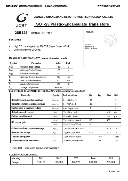
μA μA
Cob
* Pulse test : Pulse width ≤350μs,Duty Cycle≤2%.
CLASSIFICATION OF hFE(1) Marking Range BV1 110-180 BV2 135-220 BV3 170-270 BV4 200-320 BV5 250-400
Dimensions In Inches Min. Max. 0.035 0.045 0.000 0.004 0.035 0.041 0.012 0.020 0.003 0.006 0.110 0.118 0.047 0.055 0.089 0.100 0.037 TYP. 0.071 0.079 0.022 REF. 0.012 0.020 0° 8°
【 南京南山半导体有限公司 — 长电贴片三极管选型资料】
JIANGSU CHANGJIANG ELECTRONICS TECHNOLOGY CO., LTD
SOT-23 Plastic-Encapsulate Transistors
2SB624
FEATURES High DC current gain. hFE:200 TYP.(VCE=-1V,IC=-100mA) Complimentary to 2SD596.
1.BASE 2.EMITTER 3.COLLECTOR
TRANSISTOR (PNP)
SOT-23
MAXIMUM RATINGS (Ta=25℃ unless otherwise noted)
Symbol VCBO VCEO VEBO IC PD TJ Tstg Parameter Collector-Base Voltage Collector-Emitter Voltage Emitter-Base Voltage Collector Current -Continuous Total Device Dissipation Junction Temperature Storage Temperature Value -30 -25 -5 -700 200 150 -55-150 Unit V V V mA mW ℃ ℃
2SB系列晶体管参数
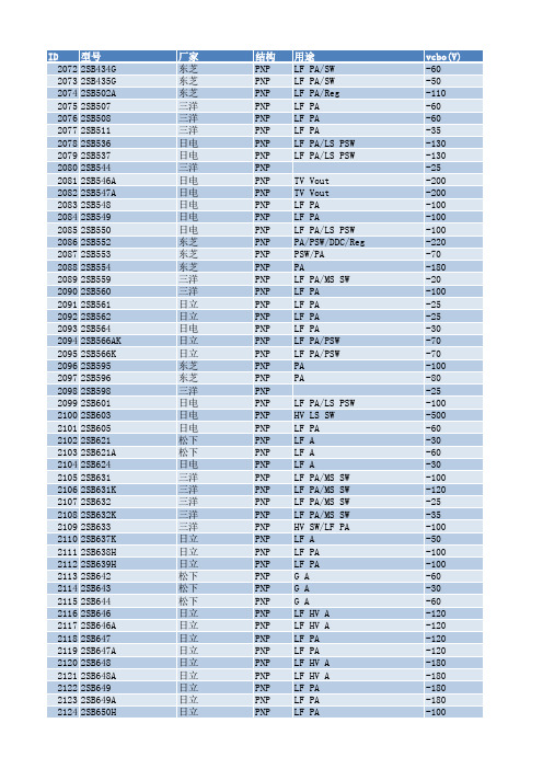
结构 PNP PNP PNP PNP PNP PNP PNP PNP PNP PNP PNP PNP PNP PNP PNP PNP PNP PNP PNP PNP PNP PNP PNP PNP PNP PNP PNP PNP PNP PNP PNP PNP PNP PNP PNP PNP PNP PNP PNP PNP PNP PNP PNP PNP PNP PNP PNP PNP PNP PNP PNP PNP PNP
松下 松下 松下 松下 日立 松下 松下 松下 松下 日电
日电 日电 日电 日电 日电 日电 日电 三洋 日电 日电 三洋 三洋 三洋 松下 罗姆 罗姆 三洋 三洋 三洋 三洋 日立 东芝 东芝 松下 日电 日电 富士电机 富士电机 罗姆 罗姆 日立 日立 日立 日立 日立 日立 富士电机 东芝 三洋 松下 松下 松下 日立 三洋
vcbo(V) -60 -50 -110 -60 -60 -35 -130 -130 -25 -200 -200 -100 -100 -100 -220 -70 -180 -20 -100 -25 -25 -30 -70 -70 -100 -80 -25 -100 -500 -60 -30 -60 -30 -100 -120 -25 -35 -100 -50 -100 -100 -60 -30 -60 -120 -120 -120 -120 -180 -180 -180 -180 -100
2SA1020中文资料(secos)中文数据手册「EasyDatasheet - 矽搜」

1.60 Max
E 0.35 0.65 M 0.00 0.40
F 0.30 0.51 N
4.00 Min
G
1.50 TYP.
(T = 25°C除非另有说明)
符号 V V V I P
T ,T
额定值
-50 -50 -5 -2 900 150, -55~150
单元
V V V A mW °C
(T = 25°C除非另有说明)
31日 - 12月2010修订版B
基地
发射器
REF.
Millimeter Min. Max.
REF.
Millimeter Min. Max.
A 5.50 6.50 H 1.70 2.05
B 8.00 9.00 J 2.70 3.20
C 12.70 14.50 K 0.85 1.15
D 4.50 5.30 L
170205270320085115160max000040400min绝对最大额定值绝对最大额定值25c除非另有说明参数参数集电极基极电压集电极到发射极电压发射器基极电压连续集电极电流集电极耗散功率结存储温度符号符号额定值额定值50505290015055150单元单元电气特性电气特性25c除非另有说明参数参数集电极基击穿电压集电极到发射极击穿电压发射器基极击穿电压集电极截止电流发射极截止电流dc电流增益集电极到发射极饱和电压基地发射极饱和电压转换频率集电极输出电容开启时间贮存时间下降时间符号符号min
y.
第1页3
芯片中文手册,看全文,戳 特性曲线
2SA1020
-2A, -50V PNP塑封三极管
31日 - 12月2010修订版B
Any changes of specification will not be informed individually.
2SB546中文资料

Absolute maximum ratings (Ta=25 )
2
元器件交易网
SavantIC Semiconductor Product Specification
Silicon PNP Power Transistors
PACKAGE OUTLINE
2SB546
Fig.2 Outline dimensions (unindicated tolerance:±0.10 mm)
3
元器件交易网
SavantIC Semiconductor Product Specification
Silicon PNP Power Transistors
2SB546
4
2SB546
SYMBOL V(BR)CEO V(BR)CBO V(BR)EBO VCEsat ICBO IEBO hFE fT V V V
-1.0 -50 -50 240
V µA µA
MHz
hFE classifications R 40-80 O 70-140 Y 120-240
SYMBOL VCBO VCEO VEBO IC PC Tj Tstg PARAMETER Collector-base voltage Collector-emitter voltage Emitter-base voltage Collector current Collector power dissipation Junction temperature Storage temperature TC=25 CONDITIONS Open emitter Open base Open collector VALUE -200 -150 -5 -2 25 150 -55~150 UNIT V V V A W
2SB1079中文资料

2SB1079Silicon PNP Triple DiffusedApplicationLow frequency power amplifier complementary pair with 2SD1559 Outline2SB10792Absolute Maximum Ratings (Ta = 25°C)ItemSymbol Ratings Unit Collector to base voltage V CBO –100V Collector to emitter voltage V CEO –100V Emitter to base voltage V EBO –7V Collector current I C –20A Collector peak current I C(peak)–30A Base currentI B –3A Collector power dissipation P C *1100W Junction temperature Tj 150°C Storage temperature Tstg–55 to +150°CNote:1.Value at T C = 25°C.Electrical Characteristics (Ta = 25°C)ItemSymbol Min Typ Max Unit Test conditions Collector to base breakdown voltageV (BR)CBO–100——V I C = –0.1 mA, I E = 0Collector to emitter breakdown voltageV (BRCEO –100——V I C = –25 mA, R BE = ∞Collector to emitter sustain voltageV CEO(sus)–100——V I C = –200 mA, R BE = ∞*1Emitter to base breakdown voltageV (BR)EBO –7——V I E = –50 mA, I C = 0Collector cutoff current I CBO ——–100µA V CB = –100 V, I E = 0I CEO ——–1.0mAV CE = –80 V, R BE = ∞DC current transfer ratio h FE 1000—20000V CE = –3 V, I C = –10 A*1Collector to emitter saturation voltageV CE(sat)1——–2.0V I C = –10 A, I B = –20 mA*1Base to emitter saturation voltageV BE(sat)1——–2.5V Collector to emitter saturation voltageV CE(sat)2——–3.0V I C = –20 A, I B = –200 mA*1Base to emitter saturation voltage V BE(sat)2——–3.5V Turn on time t on —0.6—µs I C = –10 A, I B1 = –I B2 = –20 mA Storage time t stg—3.5—µsNote:1.Pulse Test.2SB107932SB10794Hitachi CodeJEDECEIAJWeight (reference value)TO-3P—Conforms5.0 gUnit: mmCautions1.Hitachi neither warrants nor grants licenses of any rights of Hitachi’s or any third party’s patent,copyright, trademark, or other intellectual property rights for information contained in this document.Hitachi bears no responsibility for problems that may arise with third party’s rights, includingintellectual property rights, in connection with use of the information contained in this document.2.Products and product specifications may be subject to change without notice. Confirm that you have received the latest product standards or specifications before final design, purchase or use.3.Hitachi makes every attempt to ensure that its products are of high quality and reliability. However,contact Hitachi’s sales office before using the product in an application that demands especially high quality and reliability or where its failure or malfunction may directly threaten human life or cause risk of bodily injury, such as aerospace, aeronautics, nuclear power, combustion control, transportation,traffic, safety equipment or medical equipment for life support.4.Design your application so that the product is used within the ranges guaranteed by Hitachi particularly for maximum rating, operating supply voltage range, heat radiation characteristics, installationconditions and other characteristics. Hitachi bears no responsibility for failure or damage when used beyond the guaranteed ranges. Even within the guaranteed ranges, consider normally foreseeable failure rates or failure modes in semiconductor devices and employ systemic measures such as fail-safes, so that the equipment incorporating Hitachi product does not cause bodily injury, fire or other consequential damage due to operation of the Hitachi product.5.This product is not designed to be radiation resistant.6.No one is permitted to reproduce or duplicate, in any form, the whole or part of this document without written approval from Hitachi.7.Contact Hitachi’s sales office for any questions regarding this document or Hitachi semiconductor products.Hitachi, Ltd.Semiconductor & Integrated Circuits.Nippon Bldg., 2-6-2, Ohte-machi, Chiyoda-ku, Tokyo 100-0004, Japan Tel: Tokyo (03) 3270-2111 Fax: (03) 3270-5109Copyright ' Hitachi, Ltd., 1999. All rights reserved. Printed in Japan.Hitachi Asia Pte. Ltd.16 Collyer Quay #20-00Hitachi TowerSingapore 049318Tel: 535-2100Fax: 535-1533URLNorthAmerica : http:/Europe : /hel/ecg Asia (Singapore): .sg/grp3/sicd/index.htm Asia (Taiwan): /E/Product/SICD_Frame.htm Asia (HongKong): /eng/bo/grp3/index.htm Japan : http://www.hitachi.co.jp/Sicd/indx.htmHitachi Asia Ltd.Taipei Branch Office3F, Hung Kuo Building. No.167, Tun-Hwa North Road, Taipei (105)Tel: <886> (2) 2718-3666Fax: <886> (2) 2718-8180Hitachi Asia (Hong Kong) Ltd.Group III (Electronic Components)7/F., North Tower, World Finance Centre,Harbour City, Canton Road, Tsim Sha Tsui,Kowloon, Hong Kong Tel: <852> (2) 735 9218Fax: <852> (2) 730 0281 Telex: 40815 HITEC HXHitachi Europe Ltd.Electronic Components Group.Whitebrook ParkLower Cookham Road MaidenheadBerkshire SL6 8YA, United Kingdom Tel: <44> (1628) 585000Fax: <44> (1628) 778322Hitachi Europe GmbHElectronic components Group Dornacher Stra§e 3D-85622 Feldkirchen, Munich GermanyTel: <49> (89) 9 9180-0Fax: <49> (89) 9 29 30 00Hitachi Semiconductor (America) Inc.179 East Tasman Drive,San Jose,CA 95134 Tel: <1> (408) 433-1990Fax: <1>(408) 433-0223For further information write to:。
肖特基二极管参数表

肖特基二极管参数表摘要:1.肖特基二极管的基本概念和特点2.肖特基二极管的分类和应用领域3.常用肖特基二极管的型号与参数4.肖特基二极管的主要性能指标及其意义5.选择和使用肖特基二极管时需关注的因素正文:肖特基二极管(Schottky Barrier Diode,简称SBD)是一种低功耗、大电流、超高速半导体器件。
它以金属与半导体接触形成的金属半导体结原理制作,而非利用PN结原理。
由于其独特的性能优势,被广泛应用于开关电源、变频器、驱动器等电路中。
肖特基二极管的特点包括:1.低功耗:正向导通压降仅0.4V左右,整流电流可达到几千毫安。
2.高速度:反向恢复时间极短,可达到几纳秒。
3.良好的热稳定性:具有较高的热稳定性,可以承受较高的功耗。
根据应用领域和性能要求,肖特基二极管可分为不同类型。
例如,用于续流二极管、保护二极管等。
在通信电源、变频器等电路中,肖特基二极管有着广泛的应用。
常用的肖特基二极管型号包括:1.引线式肖特基二极管:D80-004、B82-004等。
2.封装式肖特基二极管:MBR1545、MBR2535、MBR300100CT、MBR400100CT等。
在选择和使用肖特基二极管时,需要关注以下性能指标:1.正向电压VF:指肖特基二极管正向导通时,正向电压与正向电流的比值。
VF越低,功耗越小。
2.反向漏电IR:指二极管反向漏电流。
IR越小,二极管的反向性能越好。
3.反向电压VR:二极管能承受的最大反向电压。
VR越高,二极管的耐压能力越强。
4.反向恢复时间trr:二极管从反向导通到截止的时间。
trr越小,二极管的开关速度越快。
总之,肖特基二极管具有低功耗、高速度等优点,广泛应用于高频、低压、大电流整流二极管、续流二极管、保护二极管等电路。
2SB647中文资料

Hitachi Code JEDEC EIAJ Weight (reference value)
TO-92 Mod — Conforms 0.35 g
Cautions
1. Hitachi neither warrants nor grants licenses of any rights of Hitachi’s or any third party’s patent, copyright, trademark, or other intellectual property rights for information contained in this document. Hitachi bears no responsibility for problems that may arise with third party’s rights, including intellectual property rights, in connection with use of the information contained in this document.
2SB647
2SB647A
Item
Symbol Min Typ Max Min Typ Max Unit Test conditions
Collector to base breakdown voltage
V(BR)CBO –120 — — –120 — — V
IC = –10 µA, IE = 0
4. Design your application so that the product is used within the ranges guaranteed by Hitachi particularly for maximum rating, operating supply voltage range, heat radiation characteristics, installation conditions and other characteristics. Hitachi bears no responsibility for failure or damage when used beyond the guaranteed ranges. Even within the guaranteed ranges, consider normally foreseeable failure rates or failure modes in semiconductor devices and employ systemic measures such as failsafes, so that the equipment incorporating Hitachi product does not cause bodily injury, fire or other consequential damage due to operation of the Hitachi product.
ASTMB62-2024混合青铜或少量金属铸件标准规范

ASTMB62-2024混合青铜或少量金属铸件标准规范
首先,ASTMB62-2024规定了混合青铜和少量金属铸件的化学成分要求。
根据不同的合金,规定了铜、锌、锡、铝、铅等合金元素的含量范围。
这个范围是根据合金的性质、使用环境和铸件特性来确定的,以确保铸件
具有所需的性能。
其次,ASTMB62-2024对混合青铜和少量金属铸件的物理性能进行了
规定。
这包括铸件的密度、熔点范围、热膨胀系数、导热系数等方面的要求。
这些物理性能的规定是为了确保铸件在实际使用中能够满足要求,具
有足够的强度、韧性和热稳定性。
此外,ASTMB62-2024还对混合青铜和少量金属铸件的机械性能进行
了规定。
这包括铸件的拉伸强度、屈服强度、延伸率、硬度等方面的要求。
这些机械性能的规定是为了确保铸件在受力情况下能够承受较大的载荷,
并具有足够的塑性和韧性。
最后,ASTMB62-2024对混合青铜和少量金属铸件的造型要求进行了
规定。
这包括铸件的设计、铸造方法、冷却方式、后处理等方面的要求。
这些造型要求的规定是为了确保铸件能够获得满足设计要求的形状和尺寸,并避免缺陷如气孔、夹杂物等。
总之,ASTMB62-2024对混合青铜和少量金属铸件的标准规范涵盖了
化学成分、物理性能、机械性能和造型要求等方面的要求。
这些规定是为
了确保铸件在实际使用中能够满足要求,具有足够的强度、韧性和热稳定性,并具备满足设计要求的形状和尺寸。
FOSAN富信电子 三级管 2SB624-产品规格书

安徽富信半导体科技有限公司ANHUI FOSAN SEMICONDUCTOR TECHNOLOGY CO.,LTD.2SB624 SOT-23Bipolar Transistor双极型三极管▉Features特点PNP Power Amplifier功率放大▉Absolute Maximum Ratings最大额定值Characteristic特性参数Symbol符号Rat额定值Unit单位Collector-Base Voltage集电极基极电压V CBO-30V Collector-Emitter Voltage集电极发射极电压V CEO-25V Emitter-Base Voltage发射极基极电压V EBO-5V Collector Current集电极电流I C-700mA Power dissipation耗散功率P C(T a=25℃)200mW Thermal Resistance Junction-Ambient热阻RΘJA625℃/WJunction and Storage TemperatureT J,T stg-55to+150℃结温和储藏温度■Device Marking产品打标H FE(1)110-180135-220170-270200-320250-400Mark BV1BV2BV3BV4BV5ANHUI FOSAN SEMICONDUCTOR TECHNOLOGY CO.,LTD.2SB624■ElectricalCharacteristics 电特性(T A =25℃unless otherwise noted 如无特殊说明,温度为25℃)Characteristic 特性参数Symbol 符号Min 最小值Type 典型值Max 最大值Unit 单位Collector-Base Breakdown V oltage集电极基极击穿电压(I C =-100µA ,I E =0)BV CBO -30——V Collector-Emitter Breakdown Voltage 集电极发射极击穿电压(I C =-1mA ,I B =0)BV CEO -25——V Emitter-Base Breakdown V oltage发射极基极击穿电压(I E =-100µA ,I C =0)BV EBO -5——V Collector-Base Leakage Current集电极基极漏电流(V CB =-30V ,I E =0)I CBO ——-100nA Emitter-Base Leakage Current发射极基极漏电流(V EB =-5V ,I C =0)I EBO ——-100nADC Current Gain直流电流增益(V CE =-1V ,I C =-100mA)H FE (1)110—400DC Current Gain直流电流增益(V CE =-1V ,I C =-700mA)H FE (2)50——Collector-Emitter Saturation Voltage 集电极发射极饱和压降(I C =-700mA ,I B =-70mA)V CE(sat)——-0.6V Base-Emitter Saturation V oltage 基极发射极饱和压降(I C =-700mA ,I B =-70mA)V BE(sat)——-1.2V Base-Emitter On Voltage 基极发射极导通压降(V CE =-6V ,I C =-10mA)V BE(on)-0.6—-0.7V Transition Frequency特征频率(V CE =-6V ,I C =-10mA)f T —160—MH Z Output Capacitance输出电容(V CB =-6V ,I E =0,f=1MH Z )C ob—17—pFANHUI FOSAN SEMICONDUCTOR TECHNOLOGY CO.,LTD.2SB624■Typical Characteristic Curve典型特性曲线ANHUI FOSAN SEMICONDUCTOR TECHNOLOGY CO.,LTD.2SB624■Dimension外形封装尺寸Symbol Dimensions In Millimeters Dimensions In Inches Min Max Min Max A 0.900 1.1500.0350.045A10.0000.1000.0000.004A20.900 1.0500.0350.041b 0.3000.5000.0120.020c 0.0800.1500.0030.006D 2.800 3.0000.1100.118E 1.200 1.4000.0500.055E1 2.2502.5500.0890.100e 0.950TYP0.037TYPe1 1.8002.0000.0710.079L 0.550REF0.022REFL10.3000.5000.0120.020θ0o8o 0o8o。
