PL34120191000GFEX中文资料
XP341使用手册

用户如果需要查阅自学习参数可以通过点击自学习参数按钮,此时卡件将回送自学习参数。自 学习参数仅是用户填写设定参数的一个参考,卡件工作所依据的参数是用户设定的参数。
自学习功能仅在系统调试阶段使用,严禁在系统正常开车阶段使用。
型号
XP341
卡件电源
5V 供电电源
(5±0.3)VDC,Imax<100mA
24V 供电电源
(24±0.5)VDC,Imax<120mA
输入回路
通道数
2路
反馈信号 类型
电流/输入阻抗 电阻
(4~20)mA/100Ω 1kΩ(需要定制)
反馈信号精度 开关量输入(上、下限输入)
输出 控制精度 冗余功能 隔离方式
4
XP341 使用手册
4.6 组态说明
PAT 信号必须组在回路中进行使用,回路的输出 MV 即 PAT 信号的阀位设定值。PAT 组态和一 般的 I/O 的组态并无太大区别,依次为控制站组态、数据转发卡组态、I/O(卡件)组态和信号点组 态。PAT 通道点组态,通过图 4-3 来进行详细说明:
反馈类型:电阻型和(4~20)mA 电流反馈两种可选,这要根据具体的电动执行机构的反馈类 型选择。XP341 现在只能采集电流反馈信号,但留出了测量电阻信号的接口,如要测电阻反馈信号 需定做卡件。
隔离电压
共模抑制比 串模抑制比 断线检测
0.3%FS
<1kΩ:ON 报警;>100kΩ:OFF 24V 有源输出(驱动电流 15mA) 视不同的阀门而定(小于死区)
不能冗余 光电隔离,统一隔离 500VAC 1 分钟(现场侧与系统侧) 250VAC 1 分钟(开关量、模拟量之间)
SIMATIC CP 341 快速入门指南说明书
Primeros pasosEl presente manual le guía, a través de un ejemplo concreto con cuatro pasos de puesta en servicio, hasta una aplicación de funcionamiento real que le permitirá enviar datos a través de la interfaz serie y conocer y supervisar las funciones básicas del CP 341 por cuanto respecta a hardware y a software. Las referencias al manual pretenden darle una primera visión de conjunto de las informaciones que contiene.Dependiendo de la experiencia de que se disponga, para ejecutar el ejemplo se requieren de 1 a 2 horas.RequisitosDeben cumplirse los siguientes requisitos:S Debe contar con un equipo S7-300, formado por una fuente de alimentación y una CPU.S En la PG debe haber instalado correctamente STEP 7 (≥V5.0).S Debe haber creado un proyecto para el equipo S7-300.S La PG debe estar conectada a la CPU.S Dispone de un módulo CP 341, el software de configuración correspondiente y del cable necesa-rio.S Debe haber preparado al interlocutor para la transmisión serie de datos. Si utiliza el CP 341 con interfaz RS232/V.24, también puede emplear como interlocutor una PG que tenga instalado el pro-grama “Hyper Terminal”. El programa “Hyper Terminal” se encuentra en Windows, bajo Inicio →Programas → Accesorios →Hyper Terminal. Más abajo se describe cómo arrancar el programa. Instalar el paquete de configuración en la PGEl paquete de configuración incluye una herramienta de parametrización para el CP 341, una librería con bloques de función y un ejemplo de programación.Arranque el programa de instalación del CD haciendo doble clic en el archivo SETUP.EXE.Siga las instrucciones del programa de instalación.Montar el CP 341 y conectarlo con el interlocutorEnchufe el elemento de ampliación de bus suministrado con el CP 341 en el conector de bus de la CPU. Enganche el CP 341 en el perfil soporte, abátalo hacia abajo y atorníllelo.Conecte los terminales L+ y M de su fuente de alimentación a las conexiones correspondientes del CP.Con el cable de conexión, establezca la conexión entre el CP 341 y su interlocutor. En el anexo B del manual encontrará la ocupación del conector de interfaz.Prueba:Conecte la tensión en la fuente de alimentación.Después de la fase de inicialización se encenderá el LED SF del CP 341. Parametrizar el CP 341Abra su proyecto en el Administrador SIMATIC.Dentro del proyecto, abra la tabla de configuración de HW Config.En el catálogo de hardware seleccione el CP 341 con la referencia correcta (MLFB) y arrástrelo a la ranura prevista.Haciendo doble clic sobre el CP 341 se abre la pantalla “Propiedades CP 341”.Anote bajo “Adress” (Dirección) la dirección del módulo (en el ejemplo 256 →100 Hex). Necesitaráeste valor para la integración en su programa de usuario.Haga clic en el botón Parámetros y seleccione el protocolo “ASCII”. Haga doble clic en el Sobre. Haciendo clic en el botón Aceptar, acepte las pantallas de parametrización con el siguiente ajuste predeterminado: 9600 bit/s, 8 bits de datos, 1 bit de parada, paridad par.Guarde la parametrización con Archivo → Guardar y salga de la pantalla de parametrización con Archivo → Salir. Dentro de la pantalla “Propiedades CP 341”, haga clic en el botón Aceptar.Guarde en su proyecto la configuración que ha creado pulsando Equipo → Guardar y compilar. Estando la CPU en STOP, transfiera la configuración con los comandos Sistema de destino → Cargar en módulo.Los datos se transfieren directamente a la CPU y al CP 341. Si la carga se efectúa sin errores se apaga el LED SF.Cierre HW Config pulsando Equipo → Salir.Integración en el programa de usuarioAl instalar el paquete de configuración ha instalado el proyecto de ejemplo “CP340_41” en la librería \Siemens\STEP7\Examples.Vaya al Administrador SIMATIC y abra el proyecto de ejemplo con los comandos Archivo → Abrir... →Proyectos y haga doble clic en el subproyecto “CP341Protocol 3964” (sirve también para protocolos ASCII).Abra el programa S7 de la CPU de este subproyecto. Haga doble clic en la carpeta “Blocks”(bloques).Copie en su proyecto, además de los datos del sistema, todos los bloques con Equipo SIMATIC300→ CPU3xx → Programa S7 → Bloques.S FC21FC con SENDS FC22FC con RECEIVES DB21, DB22DBs de instancia para los FBs estándarS DB40, DB41DBs de trabajo para los FBs estándarS DB42DB desde el que se envíaS DB43DB en el que se depositan los datos recibidosS OB1OB cíclicoS OB100Rearranque OB (de rearranque en caliente)S VAT1Tabla de variablesS FB7, FB8FBs estándar para RECEIVE, SENDS SFC 58, 59SFCs para los FBs estándarAbra la FC22 de su proyecto con un doble clic y cambie la dirección del módulo “LADDR” “272” por “256” en la primera línea del segmento 1.Guarde los bloques con los comandos Archivo → Guardar.Salga del editor de la FC con los comandos Archivo → Salir.En el Administrador SIMATIC, seleccione Equipo SIMATIC 300 → CPU3xx → Programa S7 → Blo-ques.Cargue en su CPU todos los bloques S7 existentes mediante Sistema de destino → Cargar (CPU en estado STOP).Cambie la CPU a estado RUN. El CP 341 comienza a enviar datos cíclicamente a través de la interfaz serie (el LED “TxD” parpadea).Si envía datos desde su interlocutor, el CP 341 los recibe en el DB 43. El destino estará registrado en los parámetros “DB_NO”, “DBB_NO” del FB7 (P_RCV_RK) en el FC22.Prueba:Haciendo doble clic en la VAT1 de su proyecto, en el directorio “Bloques”, puede observar la transferencia de datos:Cambie a Online con Sistema de destino → Establecer enlace con →CPU configurada.Cambie a Observar con Variable → Observar.Con ayuda del operando “DB42.DBW0” (contador de envíos) puede determinar el número de transferencias. En el “DB41.DBW18” (contador de recepciones) puede ver si ha recibido datos. Si emplea su PG como interlocutor, puede recibir los datos y enviar datos al CP 341 con el programa “Hyper Terminal”. Haciendo doble clic en el archivo “Getting.ht” (en \Siemens\STEP7\s7fptp\Termi-nal\....), “HyperTerminal” arranca con la configuración correcta. Se indican los datos enviados por el CP 341. Pulsando una tecla cualquiera del teclado se envía el carácter correspondiente al CP 341.DiagnósticoCualquier manejo erróneo, cableado incorrecto de la interfaz serie o parametrización incoherente puede producir errores.En el capítulo 8 del manual puede consultar cómo diagnosticar tales errores y mensajes.。
341G说明书

第三章ISA341G单元测控装置341G为变电站现场级的测控装置,具有遥测、遥信、遥控、遥调等远动功能。
采用标准4U (半层)机箱,由交流(WB7141)、CPU(WB720A)、开入(WB733)、开出(WB732)电源(WB760B)等5个插件组成,使用WB700总线板。
341G按无人值班思想设计,既可分散安装,也可集中组屏。
根据所配插件的不同,ISA341G有A、B两种型号,见附图。
1同期说明1.1功能使用装置的同期功能用于需同期的手合及遥合。
可实现一条线路的同期输出。
其中装置的第1组交流电压(P10-01~02、P9-01~02) 接入系统母线电压,装置的线路电压(对应于341GA 为P10-11、P9-11)或者第2组交流电压C相(对应于341GB为P10-08、P9-08) 接入系统线路电压,线路侧电压可接任意相电压和线电压,可界面设定线路电压相别。
装置通过开入KI2(P01-10)区分手合同期还是遥合同期,当KI2为1时,只能进行远方遥控;为0时,只能进行就地手合。
就地手合时需接入手动合闸信号KI3(P01-11),装置检测到有手合信号时,进行同期逻辑判断。
遥控合闸时,在接收到遥合报文时且KI2为1时,进行同期逻辑判断。
同期出口固定为YK1(P08-01~03)。
KI1(P01-09)定义为退出同期,用于外部退出同期检定。
状态栏图中的锁图标用于显示同期状况,有锁标志时,表示装置投入了同期功能且没有退出,当锁打开时表示同期条件不满足,当锁关闭时,表示同期条件满足。
同期是选配功能,在〖配置〗-配置保护段中可投退此功能。
当退出同期功能时,YK1、KI1~KI3可作为标准遥控和遥信使用。
1.2逻辑原理同期可选用检无压和检同期两种检定方式。
当检无压合检同期都退出时,同期开放;若检无压和检同期同时投入,则先判检无压,检无压不成功再进行检同期,原理见图1。
退退退退 IN1退退退退 IN3退退退退退退退退退YK1退退退退 IN2图1. 同期逻辑框图检同期合闸具有频差闭锁,压差闭锁,角差闭锁、频差加速度闭锁功能。
辛德勒电子October 2019控制和信号单元目录说明书

Catalog | October 2019Control and signaling units Ø 22®XB4 metal,Find your catalog>With just 3 clicks, you can reach the Industrial Automationand Control catalogs, in both English and French >Download Digi-Cat with this linkSelect your training>Find the right Training for your needs on our Global website >Locate the training center with the selector tool, using this linkQuick access to product informationGet technical information about your product•Updated quarterly•Embeds product selectors and configurators,360° images, training centers•Optimized search by commercial referenceEach commercial reference presented in a catalog contains a hyperlink. Click on it to obtain the technical information of the product:–Characteristics, Dimensions and drawings, Mounting and clearance,Connections and schemas, Performance curves–Product image, Instruction sheet, User guide, Product certifications,End of life manualGeneral contentsHarmony® XB4 metal for explosive atmospheresb Presentation .............................................................................................page 2b ReferencesFor ATEX dust offerv Spring return pushbuttons, unmarked-Illuminated and non illuminated .............................................................page 4v Mushroom head pushbuttons, spring return ...............................................page 5v Emergency stop and Emergency switching off functions ............................page 5v Selector switches with standard and long handle ........................................page 6v Key switches ...............................................................................................page 6v Pilot lights with integral LED ........................................................................page 7For Explosive atmosphere dust + gas offerv Spring return pushbuttons, unmarked-Illuminated and non illuminated .............................................................page 8v Mushroom head pushbuttons, spring return ...............................................page 9v Emergency stop and Emergency switching off functions ............................page 9v Selector switches with standard and long handle ......................................page 10v Key switches .............................................................................................page 10v Pilot lights with integral LED .......................................................................page 11v Push-to-test pilot light ................................................................................page 11v Contact and Light blocks ............................................................................page 11b Product reference index .........................................................................page 12References:Example of hazardous dust zoneZone 20Zone 21Zone 22Example of hazardous gas and vapor zoneZone 2Zone 0Zone 1PresentationThe Harmony ® XB4 Explosive atmosphere range of modular control and signaling units are designed for industries where explosive atmospheres can be present. This range is ideal for use in environments where the generation of possible ignition sources can be prevented and controlled.This range includes 2 offers that meet the different standards:b ATEX dust offer: compliant with European Directive 2014/34/EU , Zone 21/22 b Explosive atmosphere dust + gas offer: IECex Zone 1/2/21/22; UL 60079 Zone 1/ 2/21/22; NEC 500 Class 1 Div 2, Class 2 Div 2 & Class 3This range offers products for the following functionsb ATEX dust offer: illuminated and non-illuminated pushbuttons, selector and key switches, Emergency stop functions, and pilot lights.b Explosive atmosphere dust + gas offer: illuminated and non-illuminated pushbuttons, selector and key switches, Emergency stop functions, pilot lights, push-to-test pilot lights, contact and LED light blocks.Explosive atmosphere and ignition sourcesAccording to the directives, a potentially explosive atmosphere is the mixture of air with flammable substances in the form of gas, vapor, and/or dust, that whenexposed to an ignition source under normal atmospheric conditions can completely or partially catch fire and explode.The types of ignition sources that can create an explosive atmosphere are: b Hot surfaces b Flames and hot gases b Mechanically produced sparks b Electrical equipment b Transient currents b Static electricity b Lightning strikes b Electromagnetic waves b Optical radiation b Ultrasound b Chemical reactions b People (indirectly)Explosive atmospheres are found in areas like: b Metal surface grinding, especially aluminum dust and particles b Oil refineries, rigs and processing plants b Gas pipelines and distribution centers b Printing industries, paper and textiles b Aircraft refueling and hangars b Chemical processing plants b Grain handling and storage b Sewage treatment plants b Surface coating industries b Underground coal mines b Wood working areas b Sugar refineriesb Vessels/shipsb Power plantsExplosive atmosphere IECEx zones and NEC 500 class and divisionsv Food & Beveragev Oil & Gas, including petrochemical extraction & transformation, car gas stations and gas bottling plants v Chemicals v Printingv Paint manufacturing linesFor more technical information, please refer to the Harmony XB4 Explosive atmosphere products page on the Schneider Electric website.Food & Beverage Oil & GasPrinting Paint manufacturingXB4BP383B5EXX B 4E X _1038_C P O D A 2016003XB4BP482EXP F 152007BEmergency stop and Emergency switching off functionsXB4BC21EX101162XB4BS9445EX110018Presentation:Key switchesPresentation: XB4BD33EX107762XB4BJ33EXP F 106190XB4BG33EXP F 106189(50/60 Hz)Green XB4BVBG3EX 0.080/0.176Red XB4BVBG4EX 0.080/0.176Orange XB4BVBG5EX 0.080/0.176BlueXB4BVBG6EX 0.080/0.176110...120 a (50/60 Hz)21-22–White XB4BVG1EX 0.080/0.176Green XB4BVG3EX 0.080/0.176Red XB4BVG4EX 0.080/0.176Orange XB4BVG5EX 0.080/0.176BlueXB4BVG6EX 0.080/0.176230...240 a (50/60 Hz)21-22–White XB4BVM1EX 0.080/0.176Green XB4BVM3EX 0.080/0.176Red XB4BVM4EX 0.080/0.176Orange XB4BVM5EX 0.080/0.176BlueXB4BVM6EX0.080/0.176(1) For additional contacts, please use standard Harmony XB4 range contact blocks ZBE101(1 NO) and ZBE102 (1 NC)XB4BVB6EX110022Control and signaling units Ø 22Harmony XB4 metal, explosive atmosphere Explosive atmosphere dust + gas offerSpring return pushbuttons, unmarkedReferencesPresentation: XB4BP482GEXX B 4E X _1038_C P S C T 17017XB4BP583BM5GEXX B 4E X _1038_C P S C T 17023Control and signaling units Ø 22Harmony XB4 metal, explosive atmosphere Explosive atmosphere dust + gas offerMushroom head pushbuttons, spring returnEmergency stop and Emergency switching off functionsReferencesXB4BC21GEX101162XB4BS9445GEXX B 4E X _1038_C P S C T 17032XB4BS8445GEX XB4BS8444GEXX B 4E X _1038_C P S C T 17031Key switchesPresentation: XB4BD33GEXX B 4E X _1038_C P S C T 17008XB4BJ33GEXX B 4E X _1038_C P S C T 17013XB4BG33GEX X B 4E X _1038_C P S C T 17011Contact and Light blocksXB4BVBM6GEXX B 4E X _1038_C P S C T 17038XB4BW25BM5GEXX B 4E X _1038_C P S C T 17088ZBE101GEXX B 4E X _1038_C P S C T 17039ZBVBM3GEXX B 4E X _1038_C P S C T 17041Product reference index IndexXB4BC21EX5 XB4BC21GEX9 XB4BC31EX5 XB4BC31GEX9 XB4BC42EX5 XB4BC42GEX9 XB4BC51EX5 XB4BC51GEX9 XB4BC61EX5 XB4BC61GEX9 XB4BD25EX6 XB4BD25GEX10 XB4BD33EX6 XB4BD33GEX10 XB4BD53EX6 XB4BD53GEX10 XB4BG03EX6 XB4BG03GEX10 XB4BG21EX6 XB4BG21GEX10 XB4BG33EX6 XB4BG33GEX10 XB4BG41EX6 XB4BG41GEX10 XB4BG61EX6 XB4BG61GEX10 XB4BJ21EX6 XB4BJ21GEX10 XB4BJ33EX6 XB4BJ33GEX10 XB4BJ53EX6 XB4BJ53GEX10 XB4BP21EX4 XB4BP21GEX8 XB4BP31EX4 XB4BP31GEX8 XB4BP42EX4 XB4BP42GEX8 XB4BP51EX4 XB4BP51GEX8 XB4BP61EX4 XB4BP61GEX8 XB4BP181EX4 XB4BP181GEX8 XB4BP183B5EX4 XB4BP183BG5EX4 XB4BP183BM5GEX8 XB4BP183G5EX4 XB4BP183M5EX4 XB4BP381EX4 XB4BP381GEX8 XB4BP383B5EX4 XB4BP383BG5EX4 XB4BP383BM5GEX8 XB4BP383G5EX4 XB4BP383M5EX4 XB4BP482EX4 XB4BP482GEX8 XB4BP483B5EX4 XB4BP483BG5EX4 XB4BP483BM5GEX8 XB4BP483G5EX4XB4BP483M5EX4XB4BP581EX4XB4BP581GEX8XB4BP583B5EX4XB4BP583BG5EX4XB4BP583BM5GEX8XB4BP583G5EX4XB4BP583M5EX4XB4BP681EX4XB4BP681GEX8XB4BP683B5EX4XB4BP683BG5EX4XB4BP683BM5GEX8XB4BP683G5EX4XB4BP683M5EX4XB4BPS11EX4XB4BPS11GEX8XB4BPS21EX4XB4BPS21GEX8XB4BPS31EX4XB4BPS31GEX8XB4BPS42EX4XB4BPS42GEX8XB4BPS51EX4XB4BPS51GEX8XB4BPS61EX4XB4BPS61GEX8XB4BS8444GEX9XB4BS8445EX5XB4BS8445GEX9XB4BS9445EX5XB4BS9445GEX9XB4BT845EX5XB4BT845GEX9XB4BVB1EX7XB4BVB3EX7XB4BVB4EX7XB4BVB5EX7XB4BVB6EX7XB4BVBG1EX7XB4BVBG3EX7XB4BVBG4EX7XB4BVBG5EX7XB4BVBG6EX7XB4BVBM1GEX11XB4BVBM3GEX11XB4BVBM4GEX11XB4BVBM5GEX11XB4BVBM6GEX11XB4BVG1EX7XB4BVG3EX7XB4BVG4EX7XB4BVG5EX7XB4BVG6EX7XB4BVM1EX7XB4BVM3EX7XB4BVM4EX7XB4BVM5EX7XB4BVM6EX7XB4BW21BM5GEX11XB4BW23BM5GEX11XB4BW24BM5GEX11XB4BW25BM5GEX11XB4BW26BM5GEX11ZBE101GEX11ZBE102GEX11ZBVBM1GEX11ZBVBM3GEX11The information provided in this documentation contains general descriptions and/or technical characteristics of the performance of the products contained herein. This documentation is not intended as a substitute for and is not to be used for determining suitability or reliability of these products for specific user applications. It is the duty of any such user or integrator to perform the appropriate and complete risk analysis, evaluation and testing of the products with respect to the relevant specific application or use thereof. Neither Schneider Electric nor any of its affiliates or subsidiaries shall be responsible or liable for misuse of the information contained herein.Design: Schneider ElectricPhotos: Schneider ElectricSchneider Electric Industries SASHead Office35, rue Joseph Monier - CS 30323F-92500 Rueil-Malmaison CedexFranceDIA5ED2170903ENOctober 2019 - V2.0。
CPC-3414-中文说明书-A3

第一章 产品介绍
第一章
产品介绍
简介
CPC-3414 是我公司新推出的4U 14 槽3UCompactPCI 板卡系统。 系统为标准19 寸上架机型,可前后出卡。可提供1 个系统槽和13 个 扩展槽,同时增加0号槽位为系统监控模块槽位,系统监控完善,可 靠性高。
第三章 背板说明......................................................................................9 背板接口位置示意图........................................................................9 跳线功能设置..................................................................................10 电源插座..........................................................................................13 风扇插座..........................................................................................14
放静电;
d) 避免不必要的走动; e) 拿产品部件(尤其是板卡)时仅拿住边缘; f) 将产品部件置于一个接地的无静电的操作平台上。如果可能
MP3解码芯片详解之Sigmatel
MP3解码芯片详解之Sigmatel –STMP3410,由于很多开发公司都从事这块芯片开发,因此目前能做的功能越来越多,包括电子图片,歌词同步,TXT阅读,闹钟等。
但由于它的部分程序放在flash上,因此容易出现丢程序现象。
sigmatel这个系列芯片的方案,目前应该是国内机器使用最多的。
最早为我们熟悉的MSC H128、爱国者月光宝盒,一直到现在,还有非常多的国产机器使用。
另一方面,韩国机器里使用该方案的代表产品有(列举的是国内品牌,实际原厂是韩国产品):JNCSSF70、SSF800(3420芯片)、三星55(3420芯片)。
它的特点是目前开发程度较高——在开始时,该系列方案产品返修率高,现在的稳定性已经改善很多了。
而且国产产品里,用该芯片方案的比例应该是最大的。
先解释下芯片编号的意义:首先你要明确是哪个系列的:34XX系列的都是USB1.1,35XX才是USB2.0。
如果有JS说他的3410芯片支持USB2.0,别说偶没告诉你哦~!嘎嘎~~~其中34XX系列还有TA3、TA4之分,TA4较TA3的死机、漏码、丢失等现象改进不少。
(大家可以参考德劲DE-803的MP3,就是用2种芯片分2批生产的)35XX系列都是TA4的,大家可以放心购买。
再说下34XX和35XX的区别:省电、7彩背光、USB速度……而后面2位数字,应该是音质等效果,比如3501的音质就没3420的好。
偶个人觉得Sigmatel的录音确实是需要大大地改进了。
采用的是WAV波形格式,熟悉电脑的朋友肯定知道,这个是“无损录音”相当消耗内存空间,而闪存容量又小,128M的只能有大概8~12小时。
听音质,偶现在可以很肯定地听出来Sigmatel的风格了!Sigmatel给人的感觉……,呵呵,说不清楚,你自己听过就知道了~~!因为是单芯片设计,所以兼容性好,但是效能却没双芯片互补的好~但是经济嘛!偶手头的资料,大概就这么多了,以后有了还会继续增加!网友山海梦龙:SIGMATEL的芯片,开始时我觉得确实是便宜没好货:返修高、音质差、电流声、声音小……,但随着各厂商开发程度的深入,返修率逐渐低了下来,在音质表现上,也出现了象IAUDIO4(JNCSSF-800)这样化腐朽为神奇的代表产品。
Boost DC-DC芯片MP3414
The Future of Analog IC Technology
1.8A,1MHz, Synchronous, Step-up Converter with Output Disconnect
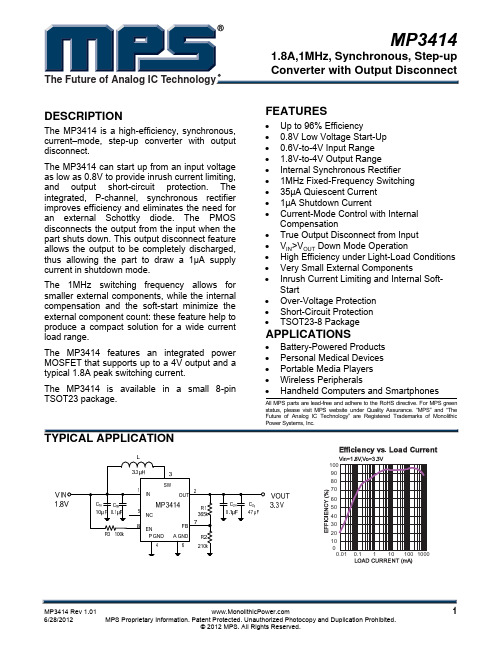
DESCRIPTION
The MP3414 is a high-efficiency, synchronous, current–mode, step-up converter with output disconnect. The MP3414 can start up from an input voltage as low as 0.8V to provide inrush current limiting, and output short-circuit protection. The integrated, P-channel, synchronous rectifier improves efficiency and eliminates the need for an external Schottky diode. The PMOS disconnects the output from the input when the part shuts down. This output disconnect feature allows the output to be completely discharged, thus allowing the part to draw a 1μA supply current in shutdown mode. The 1MHz switching frequency allows for smaller external components, while the internal compensation and the soft-start minimize the external component count: these feature help to produce a compact solution for a wide current load range. The MP3414 features an integrated power MOSFET that supports up to a 4V output and a typical 1.8A peak switching current. The MP3414 is available in a small 8-pin TSOT23 package.
SIWAREX WP341 HF weighing electronics 商品说明书

OverviewTM SIWAREX WP341 HF weighing electronicsTM SIWAREX WP341 HF weighing electronicsThe SIWAREX WP341 is a compact, precise weighing electronics in the SIMATIC ET 200SP format.With a width of just 20 mm it is one of the slimmest weighing electronics on the market, yet its firmware includes the functionalities of a continuous belt weighing electronics. Optionally the WP341can be used for operation of solids flowmeters.The load cells and the speed sensor are directly connected to the ET 200SP Base Unit (type U0) and therefore the complete system is directly integrated into the automation system.•Low space requirements with only 20 mm module width •Seamless integration into SIMATIC ET 200SP •1 000 Hz sampling rate und processing time•Dedicated firmware for continuous belt weighing applications •Operation with SIMATIC S7-300, S7-400, S7-1200 and S7-1500controllers•Operation in Ethernet IP or Modbus TCP-based systems using ET 200SP multi-field bus IM•Three digital inputs and outputs each ex works•High degree of scalability in connection with all available SIMATIC standard components•Open SIWAREX concept – all settings and parameters accessible,no encapsulated black box in the field•Unrestricted access to all scale parameters and functions from the SIMATIC S7 Controller / HMI•Internal, protocol memory for up to 1 000 000 entries•Commissioning and maintenance from HMI or weighing electronics-internal web server•Advanced diagnostic features in combination with SIWAREX DBSIWAREX WP341 offers a compact and extremely versatile solution for continuous belt weighing applications with high requirements for accuracy and performance.Typical areas of application include:•Belt weighers in recycling, mining, aggregate, cement, chemical and food industries•Easy and completely integrated realization of weigh feeding applications•Operation with solids flowmetersThe SIWAREX WP341 is a technology module of the SIMATIC ET 200SP distributed I/O system.Installation is on a type U0 BaseUnit. The load cells, serial RS 485interface and digital inputs/outputs are wired directly on theBaseUnit with user-friendly push-in terminals. This makes is quick and easy to replace weighing electronics without any wiring effort. The web server is addressed via an Ethernet interface in the weighing electronics. Should more interfaces and I/O be required, they can be added with the ET 200SP system components.The load cells of the belt scale as well as the speed sensor are directly wired to the BaseUnit. The weighing electronics internally calculates the current flow rate based on the current weight and speed signal. Six individual totalizers are available and can be easily read out of the weighing electronics into the connected CPU. The totalizers are resettable by software command or alternatively by a 24 V signal connected to one of the on board digital inputs. Different methods of commissiong are supported: by test weight, by test chain, by material batch or based on load cell data.A correction factor calculated by a material test can be applied.Additionally a correction factor curve based on different belt load levels can be defined. Digital signal filters for speed and load offer the possibility to optimize the results of the weighing process. A logging function for all calibration actions with time stamp provide a transparent and secure operation of the scale. In combination with the digital junction box SIWAREX DB up to four connected load cells can be individually monitored and diagnosed down from the single sensor up into the MES level.The free of charge function block and HMI visualization give full access to all available data and parameters of the WP341 from the controller / HMI. Therefore the belt weighing application can be easily integrated into existing HMI visualizations and allow an intuitive operation and service of the scale.© Siemens AG 2023TM SIWAREX WP341 HF weighing electronicsTM SIWAREX WP341 HF weighing electronicsTM SIWAREX WP341 HF weighing electronics。
PL34120191000GXED资料
Product may not be to scale
PRODUCT CAPABILITIES
Resistance Range Absolute Resistance Tolerance Resistance Ratio Tolerance (Reference Resistor on Pin 1) Absolute TCR Ratio TCR Absolute Resistor Stability Ratio Resistor Stability Package Power Dissipation Operating Temperature Range 500Ω to 100K 1% to 0.05% 0.1% to 0.05% ± 50ppm standard ± 5ppm standard 1000ppm/2000hours @ 70°C 300ppm/2000hours @ 70°C 500mW/ 70°C - 40°C to + 85°C, - 55°C to + 125°C
138
Document Number: 61066 Revision 14-Nov-02
C1
20 LEAD PACKAGE DIMENSIONS in inches [millimeters]
A MINIMUM 0.385 [9.78] NOMINAL 0.390 [9.91] MAXIMUM 0.395 [10.03] A1 0.348 [8.84] 0.350 [8.89] 0.352 [8.94] B 0.385 [9.78] 0.390 [9.91] 0.395 [10.03] B1 0.348 [8.84] 0.350 [8.89] 0.352 [8.94] C --0.045 [1.14] --C1 --0.045 [1.14] --D --0.015 [0.38] --D1 --0.015 [0.38] --E ------F --0.178 [4.52] --G --0.108 [2.74] --I 0.026 0.66 ----J --P ---
ch341a编程器

ch341a编程器介绍ch341a编程器是一种USB接口的通用芯片编程器,用于对各种单片机和存储器进行编程和读取操作。
该编程器支持多种芯片类型,包括EEPROM、Flash存储器和MCU等。
功能特点ch341a编程器具有以下主要功能特点:B接口:通过USB接口与计算机连接,实现编程器与计算机之间的数据传输和控制。
2.多种芯片支持:支持多种EEPROM、Flash存储器和MCU芯片的编程。
3.高速编程:支持快速编程操作,提高编程效率。
4.编程与读取操作:可以对目标芯片进行编程和读取操作,方便进行程序烧录和数据读取。
5.完善的软件支持:配套的编程软件提供了丰富的功能,包括芯片型号选择、编程参数设置、编程测试等。
使用步骤以下是使用ch341a编程器的基本步骤:1.连接编程器:将ch341a编程器通过USB接口连接到计算机。
2.安装驱动程序:根据操作系统的要求,安装ch341a编程器的驱动程序。
3.打开编程软件:运行配套的编程软件,在软件界面中点击相应的按钮或菜单,进入编程操作界面。
4.选择芯片型号:在软件界面中选择要编程的芯片型号,确保与目标芯片的型号相匹配。
5.设置编程参数:根据具体需求,设置编程参数,包括编程模式、编程电压等。
6.编程测试:对目标芯片进行编程测试,确保编程器与芯片之间的连接正常。
7.开始编程:点击软件界面中的编程按钮,开始对目标芯片进行编程操作。
8.程序烧录完成后,可以对编程结果进行验证、查看和保存。
注意事项在使用ch341a编程器时,需要注意以下事项:1.正确连接:确保将编程器正确连接到计算机的USB接口,并通过正确的方式连接到目标芯片。
2.芯片型号选择:在选择芯片型号时,需要仔细核对目标芯片的型号,并选择与之相匹配的芯片型号。
3.编程参数设置:根据目标芯片的规格书,设置正确的编程参数,如编程电压和编程模式等。
4.驱动程序安装:在使用编程器之前,需要先根据操作系统的要求,安装相应的驱动程序。
MC3419中文资料
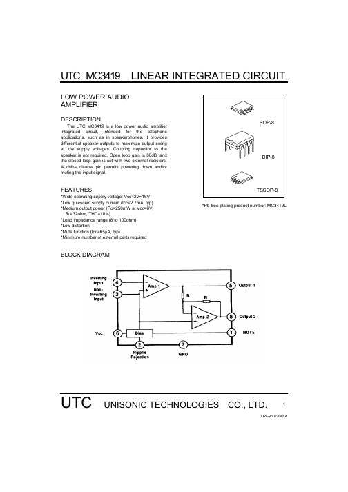
UTC MC3419 LINEAR INTEGRATED CIRCUITUTC UNISONIC TECHNOLOGIES CO., LTD.1QW-R107-042,ALOW POWER AUDIO AMPLIFIERDESCRIPTIONThe UTC MC3419 is a low power audio amplifierintegrated circuit, intended for the telephone applications, such as in speakerphones. It provides differential speaker outputs to maximize output swing at low supply voltages. Coupling capacitor to the speaker is not required. Open loop gain is 80dB, and the closed loop gain is set with two external resistors. A chips disable pin permits powering down and/or muting the input signal.FEATURES*Wide operating supply voltage: Vcc=2V~16V *Low quiescent supply current (Icc=2.7mA, typ) *Medium output power (Po=250mW at Vcc=6V, R L =32ohm, THD=10%)*Load impedance range (8 to 100ohm) *Low distortion*Mute function (Icc=65µA, typ)*Minimum number of external parts required*Pb-free plating product number: MC3419LBLOCK DIAGRAMUTC MC3419 LINEAR INTEGRATED CIRCUITUTC UNISONIC TECHNOLOGIES CO., LTD.2QW-R107-042,AABSOLUTE MAXIMUM RATINGS (Ta=25°C)PARAMETER SYMBOLVALUE UNIT Supply VoltageVcc -1 to +18 V Output CurrentIo +-250 mA Maximum Input, Ripple Rejection, Mute Pin VoltageVi -1 to +1 V Applied Output Voltage (Output Pin When Disabled)Vo -1 to +1 V Junction TemperatureTj-55 to +150°CPIN CONFIGURATIONSPIN NAME DESCRIPTION1MuteThis pin can be used to power down the IC to converse power, or for muting, or both. When at a logic “LOW” (less than 0.8V), the IC is enabled for normal operation. When at a logic “HIGH” (2V to Vcc), the IC is disabled. If Mute is open, that is equivalent to a logic “LOW”.2 Ripple Rejection A capacitor at this pin increase power supply rejection, and affects turn-on time. This pin can beleft open if the capacitor at pin 1 is sufficient. 3 Input(+) Analog Ground for the amplifiers. A 1µF capacitor at this pin ( with a 5µF capacitor at pin 8)provides 52dB( typ) of power supply rejection. Turn-on time of the circuit is affected by the capacitor on this pin. This pin can be used as an alternative input.4 Input(-) Amplifier input. The input capacitor and resistor set low frequency roll-off and input impedance.The feedback resistor is connected between this pin and output 1.5 Output 1 Amplifier 1’s output. The DC level is about (Vcc~0.7V)/2.6 Vcc DC supply voltage is applied to this pin(Vcc=2~16V).7 GND Ground pin.8 Output 2Amplifier 2’s output. This signal is equal in amplitude, but 180°out of phase with that output 1, the DC level is about (Vcc~0.7V)/2.RECOMMENDED OPERATION CONDITIONS (Ta=25°C)PARAMETER SYMBOL VALUE UNITSupply VoltageVcc 2~16VLoad Impedance Z L 8~100 ΩPeak Load CurrentI L(peak) +-200 mA Differential Gain (5KHz Bandwidth) ∆Gv 0~46 dB Voltage at MuteVi(mute) 0~Vcc V Ambient TemperatureTa -20~+70°CUTC MC3419 LINEAR INTEGRATED CIRCUITUTC UNISONIC TECHNOLOGIES CO., LTD.3QW-R107-042,AELECTRICAL CHARACTERISTICS (Vcc=6V, Ta=25°C, unless otherwise specified)PARAMETER SYMBOLTEST CONDITIONS MINTYP MAX UNITDC PARAMETEROperating Current Icc Vcc=3V, Mute=0.8V 2.7 4 mA Vcc=16V, Mute=0.8V 3.3 5 mA Vcc=3V, Mute=2V 65 100 µA Output Voltage Vo R L =16Ω, R1=75K Ω Vcc=3V 1 1.15 1.25 V Vcc=6V 2.65 V Vcc=12V 5.65 V Output Offset Voltage Voo Vcc=6V, Rf=75K Ω,R L =32Ω -30 0 30 mV Output High Level V OH 2V<Vcc<16V, Iout=-75mA Vcc~1 V Output Low Level V OL 2V<Vcc<16V, Iout=75mA 0.16 V Input Bias Current Ibias -100 -200 nA Equivalent Resistance R EQ Pin 1 100 150 220 K Ω Pin 8 18 25 40 K Ω AC PARAMETEROpen Loop Gain of Amp. 1 Gv1 80 dB Open Loop Gain of Amp. 2 Gv2 f=1KHz, R L =32Ω -0.350 0.35 dB Output Power Po Vcc=3V, R L =6Ω, THD<10%55 mW Vcc=6V, R L =32Ω, THD<10%250 mW Vcc=12V, R L =100Ω, THD<10%400 mW Total Harmonic Distortion (f=1KHz) THD Vcc=6V, R L =32Ω, Po=125mW 0.5 1 % Vcc<3V, R L =8Ω, Po=20mW0.5 % Vcc<12V, R L =32Ω, Po=200mW0.6 % Gain Bandwidth Product GBW 1.5 MHz Power Supply Rejection (Vcc=6V, ∆Vcc=3V) PSRR C1=∝, C2=0.01µF 50 dB C1=0.1µF, C2=0, f=1KHz 12 dB C1=1µF, C2=5µF, f=1KHz 52 dB Muting Gv(mute)Mute=2V, 1KHz<f<20KHz 70 dBUTC MC3419 LINEAR INTEGRATED CIRCUITUTC UNISONIC TECHNOLOGIES CO., LTD.4QW-R107-042,ATYPICAL PERFORMANCE CHARACTERISTICSUTC MC3419UTC MC3419UTC MC3419。
磐启微电子 PAN2418 系列 2.4GHz 宽带无线收发芯片说明书

PAN2418系列产品说明书2.4GHz宽带无线收发芯片概述PAN2418芯片是工作在2.320~2.483GHz的宽带无线收发芯片。
该芯片集成射频收发机、频率发生器、晶体振荡器、调制解调器等功能模块,并且支持一对多组网和带ACK的通信模式。
发射输出功率、工作频道以及通信数据率均可配置。
主要特性6Mbps模式的接收灵敏度为-81dBm;最大输出功率20dBm。
其它特性四线 SPI 接口通信 SPI 接口速率最高支持20MbpsQFN24L 0404封装支持最大数据长度为512字节(两级乒乓FIFO)3M /6Mbps模式,需要晶振精度 ±60ppm 工作电压支持2.2~3.3V工作温度支持-40~+85℃GFSK通信方式 支持自动应答及自动重传支持RSSI检测功能 带自动扰码和CRC校验功能应用方案Babymonitor 无线图像传输玩具可视门铃 监控版本 修订时间 更新内容 相关文档V1.0 2017. 12目录1 命名规则 (4)1.1 PAN2418命名规则 (4)1.2 PAN2418系列产品选择 (4)2 主要电特性 (4)3 极限最大额定值 (3)4 系统结构方框图 (3)5 引脚定义 (4)6 芯片工作状态 (5)6.1 休眠模式 (6)6.2 待机模式-I(STB1) (6)6.3 待机模式-III(STB3) (7)6.4 待机模式-II(STB2) (7)6.5 接收模式 (7)6.6 发射模式 (7)7 数据通信模式 (8)7.1 普通模式 (9)7.2 增强模式 (9)7.3增强发送模式 (10)7.4 增强接收模式 (11)7.5 增强模式下的数据包识别 (11)7.6 增强模式下的PTX和PRX的时序图 (11)7.7 增强模式下的接收端一对多通信 (12)7.8 DATA FIFO (14)7.9 中断引脚 (14)8 SPI控制接口 (14)8.1 SPI指令格式 (15)8.2 SPI 时序 (17)9 控制寄存器 (18)10 数据包格式描述 (43)10.1 普通模式的数据包形式 (43)10.2 增强模式的数据包形式 (43)10.3 增强模式的ACK包形式 (43)11 典型应用电路(参考) (44)12 封装尺寸 (44)13 联系方式 (45)1 命名规则1.1 PAN2418命名规则DR 码率3 6 Mbps M f 6∆调制频偏@6Mbps 1.5 2 MHz M FCH 6频道间隔@6Mbps9 MHz 发射模式指标PRF 典型输出功率 0 17 20 dBm PRFC 输出功率范围-30 20 dBm 1PBW发射带数据调制的20dB 带宽(6Mbps)9MHz接收模式指标(注1)maxRX误码率<0.1%时的最大接收幅度 0 dBm 1RXSENS 接收灵敏度(0.1%BER)@6Mbps-81 dBm 2RXSENS接收灵敏度(0.1%BER)@3Mbps-84dBm接收模式邻道选择性CO C Ι/同频的通道选择性@6Mbps 10 dBc STC 1/Ι第1相邻道选择性@6Mbps 0 dBc ND C 2/Ι第2相邻道选择性@6Mbps -18 dBc RDC 3/Ι第3相邻道选择性@6Mbps -19 dBc 4/TH C Ι 第4相邻道选择性@6Mbps-32 dBc 接收机镜像抑制Image镜像抑制30 dBc 操作条件VDD 供电电压 2.2 3 3.3 V VSS 芯片地 0 V OH V 高电平输出电压 VDD-0.3 VDD V OLV 低电平输出电压 VSS VSS+0.3 V IH V高电平输入电压 VDD-0.3 VDD V IL V低电平输入电压VSSVSS+0.3V3 极限最大额定值表3 PAN2418系列芯片极限最大额定值 特 性条件参数值 单位最小典型最大最大额定值DD V 供电电压 -0.3 3.6 V I V 输入电压 -0.3 3.6 V O V输出电压VSS VDD Pd 总功耗(TA=-40℃~85℃)600 mW OP T 工作温度 -40 85 ℃ STG T存储温度-40125℃* 注1:使用中强行超过一项或多项极限最大额定值会导致器件永久性损坏。
IRMCF341中文数据手册
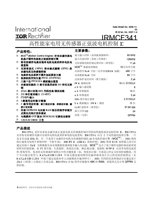
Data Sheet No. 2006-11-03IR Xi’an, No. 2007-1-4IRMCF341高性能家电用无传感器正弦波电机控制IC产品特性:n MCE TM (Motion Control Engine) -针对永磁交流电机基于硬件的高效正弦波控制引擎n 特有的硬件电路实现单电阻电流采样和电机电流重构n 支持表面式(SPM)和内嵌式磁钢(IPM)的永磁电机无传感器控制n 电流和电压采样不需外加运算放大器n 低损耗的空间矢量PWM(SVPWM)n 三路8位PWM D/A模拟输出通道n 内嵌高性能的51核可实现灵活的I/O和交互控制n JTAG接口实现8051代码仿真/调试功能n 232串行通讯端口(UART)n I2C/SPI端口n 3路通用定时器/计数器n 3路专用定时器: 看门狗定时器, 周期定时器, 捕获口定时器n 外部EEPROM与内部RAM配合的程序存储方式简化代码开发和调试n 与掩模和OTP版本IRMCK341引脚完全兼容n 1.8V/3.3V CMOS工艺主要参数:最大输入时钟(晶体振荡器频率)60 MHz 最大内部时钟(系统工作频率)128MHz 无传感器电机控制运算时间(典型值)11 μs MCE TM数据处理精度16位有符号数内部程序RAM空间(从外部E2ROM加载)48K字节内部数据RAM空间8K字节过流保护延迟时间(数字滤波) 2 μs PWM载频范围16位/ SYSCLK A/D输入通道数8 A/D转换精度12位A/D转换速度 2 μs 8051指令执行速度 2 SYSCLK D/A模拟输出(PWM)精度8 位UART波特率(典型值)57.6K bps 最大可用I/O 24 封装(无铅)QFP64产品描述IRMCF341是针对家电永磁交流正弦波电机无传感器控制应用的高性能低成本电机控制IC。
IRMCF341具有特有的硬件电路可实现单电阻电流采样和电机电流重构。
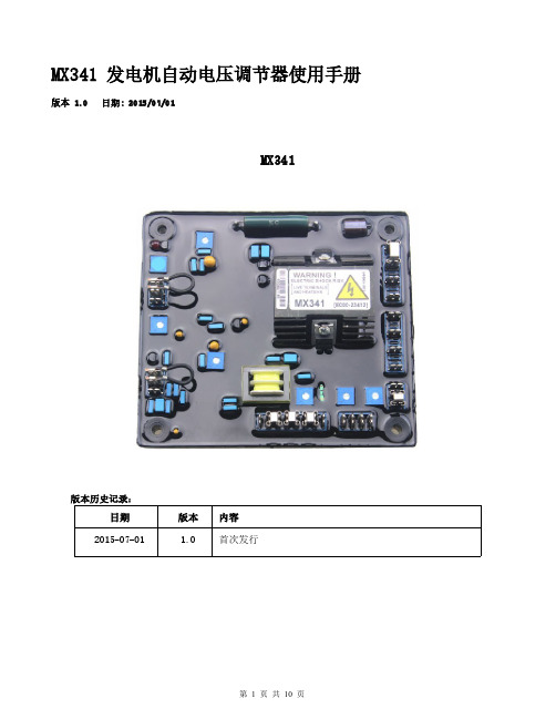
MX341中文说明书
MX341发电机自动电压调节器使用手册版本 1.0日期:2015/07/01MX341版本历史记录:日期版本内容2015-07-01 1.0首次发行目录1.技术参数 (3)2.概述 (4)3.AVR调节表 (5)4.AVR控制调节 (5)4.1.电压调节(VOLT) (5)4.2.稳定调节(STAB) (6)4.3. 4.3.低频保护调节(UFRO) (6)4.4.无功调差(DROOP) (7)4.5.电压修正调节(TRIM) (7)4.6.过励磁调节(EXC TRIP) (7)4.7.电压/频率比例调节(DIP) (7)5.安装和操作 (8)1.技术参数项目参数内容检测输入电压190-264VAC二相或三相频率50/60Hz以跨接铜片选择电源输入电压170~220VAC三相三线电流每相3A频率100~120Hz励磁场输出电压最大120VDC电流连续2.7A(注1),非连续为10秒内6A 电阻最小15Ω电压建立在AVR输入端子需剩磁电压5VAC以上消耗功率最大12Watt电流补偿负载10Ω调压精度<±1%(发动机转速变动在4%内)振动 3.3G@100~2K Hz相对湿度<95%工作温度-40~70℃(注6)储存温度-40一85℃温差称定度每℃变化,电压漂移0.05%(注2)外部电压调节用1ΩKn1Watt电位器时为士10%(注3)电压缓慢建立时间2秒发电机电流输出限制负载1Ω灵敏度范围0.5~1A过励磁保护90V(出厂预设)时间延迟固定为10秒低频保护拐点值95%Hz(出厂预设)(注4)斜率下降至30Hz时为170%电压修正(模拟输入)最大输入±5VDC(注5)灵敏度每1VDC可调节5%发电机电压输入电阻1KΩDROOP无功调差负载10Ω灵敏度0.07A对应5%压降(在PF=0时)最大输入0.33A过电压检知输入300VAC(出厂预设)时间延迟固定为1秒开关跳脱线圈电压10~30VDC/0.5Amp尺寸150mm L*135mm W 重量0.5KG±2%2.概述2.1.励磁电源来自三相永磁式发电机(PMG),如此AVR的控制电路可隔离受非线性负载所引发的影响,并能减低发电机端的射频干扰,能承受发电机的短路电流是PMG发电机的另一特色。
倍福PLC卡件介绍
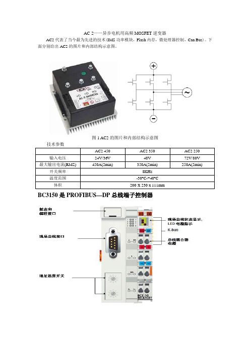
AC-2——异步电机用高频MOSFET逆变器AC2代表了当今最为先进的技术(IMS功率模块,Flash内存,微处理器控制,Can Bus)。
下面分别给出AC2的图片和内部结构示意图。
图1 AC2的图片和内部结构示意图BC3150是PROFIBUS—DP总线端子控制器总线端子控制器是带 PLC 控制功能的总线耦合器。
控制器有一个 PROFIBUS-DP 现场总线接口,可在 PROFIBUS-DP 系统中作为智能从站使用。
“紧凑型”总线端子控制器 BC3150 比较小巧而且经济。
BC3150 通过 K-BUS 总线扩展技术,可连接多达 255 个总线端子。
PROFIBUS 控制器自动检测波特率,最大可至 12 M波特率,使用两个地址选择开关分配地址。
总线端子控制器使用符合 IEC 61131-3 标准的 TwinCAT 进行编程。
组态和编程接口用于装载 PLC 程序,如果使用软件 PLC TwinCAT,则其 PLC 程序也可通过现场总线装载。
所连接的总线端子的输入/输出在 PLC 的缺省设置中被赋值。
可对每个总线端子进行配置,使其直接通过现场总线实现与上层控制单元的数据交换。
同样,预处理的数据也可通过现场总线实现总线端子控制器和上层控制器之间的数据交换。
BK3150是PRORIBUS—DP总线端子耦合器PROFIBUS-DP “紧凑型”总线耦合器 BK3150 扩展了 Beckhoff 总线端子系统,比较小巧而经济。
可以连接多达 64 个总线端子;若采用端子总线扩展技术,则可连接多达 255 个总线端子。
PROFIBUS 总线耦合器具有自动波特率检测功能,速率最大可以达到 12 Mbaud ,2 个地址选择开关用作地址分配。
对于现场总线连接,有提供 1 个 D-sub9 针接口,用于订货号为 ZS1031-3000 或 ZB3100 的 PROFIBUS 接头。
CX1020-0xxx 基本 CPU 模块CX1020 基本 CPU 模块通过一个功能更为强大的 1GHz Intel® M CPU 对现有CX1000 系列产品进行了扩展。
34112中文资料

34112 Product DetailsLanguages : English | Deutsch | Español |Português (do Brasil) | Русский | Italiano | 正體中文 (繁體) | 中文 (简体) | 日本語Country Sites : China | JapanHome | Customer Support | Supplier | Site Map | Privacy Policy | Browser Support© 2007 Tyco Electronics Corporation All Rights Reserved34112ActiveRing and Spade Tongue TerminalsRoHS Compliant (Statement of Compliance )Product Highlights: z Terminal Shape = Ring Tongue z Receptacle Style = Straight z Body Style = SOLISTRAND z Barrel Type = Closed Barrelz Wire/Cable Type = Regular Wire View all FeaturesCheck Pricing & Availability Search for ToolingProduct Feature SelectorContact Us About This ProductQuick LinksDocumentation & Additional InformationDocuments are temporarily unavailable. We are working hard to correct the problem. Please try again later.CAD Files:z None Available Additional Information:z Product Line InformationRelated Products:z ToolingProduct Features (Please use the Product Drawing for all design activity)Product Type Features:z Terminal Shape = Ring Tonguez Receptacle Style = Straight z Body Style = SOLISTRAND z Barrel Type = Closed Barrel z Wire/Cable Type = Regular Wire z Insulation = Noz Insulation Support = Non-Insulation Support z Stud Size = 10z Stud Diameter (mm [in]) = 5.00 [0.197] z Shape = RING-048 z Heavy Duty = No z Material = Copper zFinish = TinBody Related Features:z Wire Range (mm [AWG]) = 0.30-1.40² [22-16]z Wire Range (CMA) = 509 – 3,260z Barrel I.D. Min. (mm [in]) = 1.55 [0.061] z Stock Thickness (mm [in]) = 0.79 [0.031]Contact Related Features:z Class = 2Industry Standards:z Government/Industry Qualification = Yesz Government/Industry Part Number = M7928/7-4, AS7928/7-4 z RoHS/ELV Compliance = RoHS compliant, ELV compliant z Lead Free Solder Processes = Not relevant for lead free process zRoHS/ELV Compliance History = Always was RoHS compliantPackaging Related Features:z Packaging Method = Loose PieceOther:z Brand = AMPProvide Website Feedback | Contact Customer SupportSunday, April 15, 2007Page 1of 134112 Product Details - Tyco Electronics 4/15/2007/TE/bin/TE.Connect?C=1&M=BYPN&PID=43533&PN...元器件交易网。
FPGA可编程逻辑器件芯片EPM240GF100I5N中文规格书

Stratix II GX ArchitectureM512 RAM blocks can have different clocks on its inputs and outputs.The wren, datain, and write address registers are all clocked togetherfrom one of the two clocks feeding the block. The read address, rden, andoutput registers can be clocked by either of the two clocks driving theblock, allowing the RAM block to operate in read and write or input andoutput clock modes. Only the output register can be bypassed. The sixlabclk signals or local interconnect can drive the inclock, outclock,wren, rden, and outclr signals. Because of the advanced interconnectbetween the LAB and M512 RAM blocks, ALMs can also control the wrenand rden signals and the RAM clock, clock enable, and asynchronousclear signals. Figure2–49 shows the M512 RAM block control signalgeneration logic.Figure2–49.M512 RAM Block Control SignalsStratix II GX Device Handbook, Volume 1TransceiversFigure2–4.Transmitter PLL Block Note(1)Note to Figure2–4:(1)The global clock line must be driven by an input pin.The transmitter PLLs support data rates up to 6.375 Gbps. The input clockfrequency is limited to 622.08 MHz. An optional pll_locked port isavailable to indicate whether the transmitter PLL is locked to thereference clock. Both transmitter PLLs have a programmable loopbandwidth parameter that can be set to low, medium, or high. The loopbandwidth parameter can be statically set in the Quartus II software.Table2–2 lists the adjustable parameters in the transmitter PLL.Table2–2.Transmitter PLL SpecificationsParameter SpecificationsInput reference frequency range50 MHz to 622.08 MHzData rate support600 Mbps to 6.375 GbpsMultiplication factor (W)1, 4, 5, 8, 10, 16, 20, 25Bandwidth Low, medium, or highStratix II GX Device Handbook, Volume 1I/O StructureFigure2–75.Stratix II GX Device Fast PLLNotes to Figure2–75:(1)The global or regional clock input can be driven by an output from another PLL, a pin-driven dedicated global orregional clock, or through a clock control block provided the clock control block is fed by an output from another PLL or a pin-driven dedicated global or regional clock. An internally generated global signal cannot drive the PLL.(2)In high-speed differential I/O support mode, this high-speed PLL clock feeds the serializer/deserializer (SERDES)circuitry. Stratix II GX devices only support one rate of data transfer per fast PLL in high-speed differential I/O support mode.(3)This signal is a differential I/O SERDES control signal.(4)Stratix II GX fast PLLs only support manual clock switchover.f Refer to the PLLs in Stratix II & Stratix II GX Devices chapter in volume 2of the Stratix II GX Device Handbook for more information on enhancedand fast PLLs. Refer to “High-Speed Differential I/O with DPA Support”on page2–136 for more information on high-speed differential I/Osupport.I/O Structure The Stratix II GX IOEs provide many features, including:■Dedicated differential and single-ended I/O buffers■ 3.3-V, 64-bit, 66-MHz PCI compliance■ 3.3-V, 64-bit, 133-MHz PCI-X 1.0 compliance■Joint Test Action Group (JTAG) boundary-scan test (BST) support■On-chip driver series termination■On-chip termination for differential standards■Programmable pull-up during configuration■Output drive strength control■Tri-state buffers■Bus-hold circuitry■Programmable pull-up resistors■Programmable input and output delaysStratix II GX Device Handbook, Volume 1。
合肥电子1410交换机系列产品介绍说明书

Product overviewThe HPE 1410 Switch Series comprises unmanaged Gigabit Ethernet and Fast Ethernet switches, designed for small businesses looking for entry-level low-cost networking solutions that come with a limited lifetime warranty. The series consists of nine models with flexible mounting options to meet different network switching needs. All models have quality of service (QoS) support and IEEE 802.3x flow control features that provide outstanding data efficiency.Simplified plug-and-play convenience is enabled by features such as auto-MDIX and auto-speed negotiation. Hewlett Packard Enterprise has innovated and combined the latest advances in silicon technology to bring you some of the most power-efficient switches—1410-24G-R, 1410-16, and 1410-24 models are advanced IEEE 802.3az-compliant unmanaged Gigabit and Fast Ethernet switches. The switches come with built-in green features and a limited lifetime warranty, making the series the right choice for organizations seeking a networking solution that’s both economical and reliable.A summary of the highlights of the 1410 Switch Series:• Unmanaged Gigabit Ethernet and Fast Ethernet switches • Green features for low power consumption • Fan-less design for silent operation • QoS support• Limited Lifetime warrantyHPE 1410 Switch SeriesData sheetFeatures and benefitsQoS• IEEE 802.1p prioritizationDelivers data to devices, based on the priority and type of traffic• DiffServ Code Point (DSCP) supportAllows real-time traffic prioritization, based on L3 TOS/DSCP parametersConnectivity• Auto-MDIXProvides automatic adjustments for straight-through or crossover cables on all 10/100 and 10/100/1000 portsPerformance• NEW Energy-efficient Ethernet supportSupports new IEEE 802.3az standard; and allows lower power consumption, when operated with IEEE-compliant client devices in 100 Mb/s mode only (JG708A, J9662A, and J9663A)• Half-/full-duplex auto-negotiating capability on every portDoubles the throughput of every port• NEW Jumbo frame supportAllows frames up to 9,216 bytes to be switched through the network (Gigabit Ethernet models)• Mini jumbo-frame supportAllows frames up to 2,048 bytes to be switched through the network, which supports large data transfers (J9662A and J9663A)Ease of use• UnmanagedProvides plug-and-play simplicity• Comprehensive LED display with per-port indicatorsProvides an at-a-glance view of the status, activity, speed, and full-duplex operation of the switches • Flow controlHelps ensure reliable communications during full-duplex operation• Auto-speed negotiationSelects individual port speed automatically, depending on client capabilities; removing the need for manual intervention enables simple plug-and-play operationFlexibility• Fan-less designEnables quiet operation for deployment in open spaces• NEW Internal power supplyDelivers operational convenience and an environment suitable for business operations (JG708A, J9561A, and JD986B)Warranty and support• Limited Lifetime WarrantySee /networking/warrantysummary for warranty and support information included with your product purchase.HPE 1410 Switch SeriesSPECIFICATIONS HPE 1410-8G Switch (J9559A)HPE 1410-16G Switch (J9560A)HPE 1410-24G-R Switch (JG708A) Ports8 RJ-45 autosensing 10/100/1000ports (IEEE 802.3 Type 10BASE-T,IEEE 802.3u Type 100BASE-TX,IEEE 802.3ab Type 1000BASE-T);Media Type: Auto-MDIX; Duplex:10BASE-T/100BASE-TX: half or full;1000BASE-T: full onlySupports a maximum of 8 autosensing10/100/1000 ports16 RJ-45 autosensing 10/100/1000ports (IEEE 802.3 Type 10BASE-T,IEEE 802.3u Type 100BASE-TX,IEEE 802.3ab Type 1000BASE-T);Media Type: Auto-MDIX; Duplex:10BASE-T/100BASE-TX: half or full;1000BASE-T: full onlySupports a maximum of 16 autosensing10/100/1000 ports24 RJ-45 autosensing 10/100/1000ports (IEEE 802.3 Type 10BASE-T,IEEE 802.3u Type 100BASE-TX,IEEE 802.3ab Type 1000BASE-T);Media Type: Auto-MDIX; Duplex:10BASE-T/100BASE-TX: half or full;1000BASE-T: full onlySupports a maximum of 24 autosensing10/100/1000 portsPhysical characteristicsWeight6.14(w) x 3.8(d) x 0.96(h) in(15.6 x 9.65 x 2.45 cm)0.74 lb (0.34 kg)8.21(w) x 4.41(d) x 1.73(h) in(20.85 x 11.2 x 4.4 cm) (1U height)1.43 lb (0.65 kg)17.32(w) x 6.81(d) x 1.73(h) in(44 x 17.3 x 4.4 cm) (1U height)6.61 lb (3 kg)Memory and processor 4 Kb EEPROM capacity;packet buffer size: 192 KB512 Kb flash; packet buffer size: 512 KB 1 MB flash; packet buffer size: 512 KBMounting Wall, desktop and under-table mounting Mounts in an EIA standard 19-inch telcorack (hardware included); wall, desktopand under-table mountingMounts in an EIA standard 19-inch telco rack(hardware included); desktop mountingPerformance100 Mb Latency1000 Mb LatencyThroughputSwitching capacityMAC address table size< 3.6 µs (LIFO 64-byte packets)< 1.2 µs (LIFO 64-byte packets)up to 11.9 million pps (64-byte packets)16 Gb/s4096 entries< 8.0 µs (LIFO 64-byte packets)< 3.6 µs (LIFO 64-byte packets)up to 23.8 million pps (64-byte packets)32 Gb/s8192 entries< 8.0 µs (LIFO 64-byte packets)< 3.6 µs (LIFO 64-byte packets)35.7 million pps (64-byte packets)48 Gb/s8192 entriesEnvironmentOperating temperatureOperating relative humidityNonoperating/Storage temperatureNonoperating/Storage relative humidityAltitudeAcoustic32°F to 104°F (0°C to 40°C)15% to 95% @ 104°F (40°C), noncondensing-40°F to 158°F (-40°C to 70°C)15% to 90% @ 149°F (65°C), noncondensingup to 10,000 ft (3 km)Power: 0 dB No fan32°F to 104°F (0°C to 40°C)15% to 95% @ 104°F (40°C), noncondensing-40°F to 158°F (-40°C to 70°C)15% to 90% @ 149°F (65°C), noncondensingup to 10,000 ft (3 km)Power: 0 dB No fan32°F to 104°F (0°C to 40°C)5% to 95% @ 104°F (40°C), noncondensing-40°F to 158°F (-40°C to 70°C)15% to 90% @ 149°F (65°C), noncondensingup to 16,404 ft (5 km)Power: 0 dB No fanElectrical characteristicsFrequencyMaximum heat dissipationVoltageCurrentMaximum power rating50/60 Hz41 BTU/hr (43.26 kJ/hr)100-240 VAC1.0 A12 WNotesMaximum power rating and maximumheat dissipation are the worst-casetheoretical maximum numbers providedfor planning the infrastructure withfully loaded PoE (if equipped), 100%traffic, all ports plugged in, and allmodules populated.The exact input voltage and frequencyrating are determined by the specificpower adaptor part number ordered.Please select the correct power adaptorcountry option.50/60 Hz44 BTU/hr (46.42 kJ/hr)100-240 VAC1.1 A13 WMaximum power rating and maximumheat dissipation are the worst-casetheoretical maximum numbers providedfor planning the infrastructure withfully loaded PoE (if equipped), 100%traffic, all ports plugged in, and allmodules populated.The exact input voltage and frequencyrating are determined by the specificpower adaptor part number ordered.Please select the correct power adaptorcountry option.50/60 Hz55 BTU/hr (58 kJ/hr)100-240 VAC0.3 A16 WMaximum power rating and maximumheat dissipation are the worst-casetheoretical maximum numbers providedfor planning the infrastructure withfully loaded PoE (if equipped), 100%traffic, all ports plugged in, and allmodules populated.This model provides internal powersupply. Please select the correct powercord country option.SPECIFICATIONS HPE 1410-8G Switch (J9559A)HPE 1410-16G Switch (J9560A)HPE 1410-24G-R Switch (JG708A)Safety CSA 22.2 No. 60950; EN 60950/IEC 60950; UL 60950-1 CSA 22.2 No. 60950; UL 60950-1;IEC 60950-1; EN 60950-1CSA 22.2 No. 60950; UL 60950-1;IEC 60950-1; EN 60950-1Emissions FCC Rules Part 15, Subpart B Class A FCC Rules Part 15, Subpart B Class A FCC Rules Part 15, Subpart B Class A ImmunityGenericENESDRadiatedEFT/BurstSurgeConductedPower frequency magnetic field Voltage dips and interruptions HarmonicsFlicker EN 55022 CISPR 22EN 55024, CISPR 24IEC 61000-4-2IEC 61000-4-3IEC 61000-4-4IEC 61000-4-5IEC 61000-4-6IEC 61000-4-8IEC 61000-4-11IEC 61000-3-2IEC 61000-3-3EN 55022 CISPR 22EN 55024, CISPR 24IEC 61000-4-2IEC 61000-4-3IEC 61000-4-4IEC 61000-4-5IEC 61000-4-6IEC 61000-4-8IEC 61000-4-11IEC 61000-3-2IEC 61000-3-3EN 55022 CISPR 22EN 55024, CISPR 24IEC 61000-4-2IEC 61000-4-3IEC 61000-4-4IEC 61000-4-5IEC 61000-4-6IEC 61000-4-8IEC 61000-4-11IEC 61000-3-2IEC 61000-3-3NotesIEEE 802.3az Energy Efficient Ethernet protocol is supported by the HPE 1410-24G-R (JG708A), HPE 1410-16 (J9662A) and HPE 1410-24 (J9663A) Switches.Services Refer to the Hewlett Packard Enterprisewebsite at /networking/servicesfor details on the service-level descriptionsand product numbers. For details aboutservices and response times in your area,please contact your local Hewlett PackardEnterprise sales office. Refer to the Hewlett Packard Enterprisewebsite at /networking/servicesfor details on the service-level descriptionsand product numbers. For details aboutservices and response times in your area,please contact your local Hewlett PackardEnterprise sales office.Refer to the Hewlett Packard Enterprisewebsite at /networking/servicesfor details on the service-level descriptionsand product numbers. For details aboutservices and response times in your area,please contact your local Hewlett PackardEnterprise sales office.(CONTINUED)HPE 1410 Switch SeriesSPECIFICATIONS HPE 1410-24G Switch (J9561A) HPE 1410-8 Switch (J9661A)HPE 1410-16 Switch (J9662A)Ports22 RJ-45 autosensing 10/100/1000 ports (IEEE 802.3 Type 10BASE-T, IEEE 802.3u Type 100BASE-TX, IEEE802.3ab Type 1000BASE-T); Media Type: Auto-MDIX; Duplex: 10BASE-T/100BASE-TX: half or full; 1000BASE-T: full only2 dual-personality ports; each port can be used as either an RJ-45 10/100/1000 port (IEEE 802.3 Type 10BASE-T, IEEE 802.3u Type 100BASE-TX, IEEE 802.3ab 1000BASE-T Gigabit Ethernet) or an open mini-GBIC slot (for use with mini-GBIC transceivers)Supports a maximum of 24 Gigabit Ethernet ports8 RJ-45 autosensing 10/100 ports(IEEE 802.3 Type 10BASE-T, IEEE 802.3u Type 100BASE-TX); Duplex: half or full Supports a maximum of 8 autosensing 10/100 ports16 RJ-45 autosensing 10/100 ports(IEEE 802.3 Type 10BASE-T, IEEE 802.3u Type 100BASE-TX); Duplex: half or full Supports a maximum of 16 autosensing 10/100 portsPhysical characteristics Weight13.23(w) x 6.65(d) x 1.73(h) in (33.6 x 16.9 x 4.4 cm) (1U height)2.98 lb (1.35 kg)6.14(w) x 3.74(d) x 0.97(h) in (15.6 x 9.5 x 2.46 cm) 0.74 lb (0.34 kg)8.21(w) x 4.21(d) x 1.73(h) in(20.85 x 10.69 x 4.39 cm) (1U height)1.43 lb (0.65 kg)Memory and processor 512 Kb flash; packet buffer size: 512 KB 16 Kb EEPROM; packet buffer size: 96 KB 16Kb EEPROM; packet buffer size: 2 Mb MountingMounts in an EIA standard 19-inch telco rack (hardware included); wall, desktop and under-table mountingWall, desktop and under-table mountingMounts in an EIA standard 19-inch telco rack (hardware included) wall, desktop and under-table mountingPerformance 100 Mb Latency 1000 Mb Latency ThroughputSwitching capacity MAC address table size< 8.0 µs (LIFO 64-byte packets) < 3.6 µs (LIFO 64-byte packets)up to 35.7 million pps (64-byte packets) 48 Gb/s 8192 entries< 3.7 µs (LIFO 64-byte packets) up to 1.1 million pps (64-byte packets) 1.6 Gb/s 1024 entries< 10.6 µs (LIFO 64-byte packets) up to 2.3 million pps (64-byte packets)3.2 Gb/s 8192 entriesEnvironmentOperating temperature Operating relative humidityNonoperating/Storage temperature Nonoperating/Storage relative humidity Altitude Acoustic32°F to 104°F (0°C to 40°C)15% to 95% @ 104°F (40°C), noncondensing -40°F to 158°F (-40°C to 70°C)15% to 90% @ 149°F (65°C), noncondensing up to 10,000 ft (3 km) Power: 0 dB No fan 32°F to 104°F (0°C to 40°C)15% to 95% @ 104°F (40°C), noncondensing -40°F to 158°F (-40°C to 70°C)15% to 90% @ 149°F (65°C), noncondensing up to 10,000 ft (3 km) Power: 0 dB No fan 32°F to 104°F (0°C to 40°C)5% to 95% @ 104°F (40°C), noncondensing -40°F to 158°F (-40°C to 70°C)15% to 90% @ 149°F (65°C), noncondensing up to 16,404 ft (5 km)Power: 0 dB No fanSPECIFICATIONS HPE 1410-24G Switch (J9561A) HPE 1410-8 Switch (J9661A) HPE 1410-16 Switch (J9662A) Electrical characteristicsFrequencyMaximum heat dissipation VoltageDC voltageCurrentMaximum power rating 50/60 Hz75 BTU/hr (79.13 kJ/hr)100-240 VAC0.3 A22 WNotesMaximum power rating and maximumheat dissipation are the worst-casetheoretical maximum numbers providedfor planning the infrastructure withfully loaded PoE (if equipped), 100%traffic, all ports plugged in, and allmodules populated.This model provides internal powersupply. Please select the correct powercord country option.50/60 Hz13 BTU/hr (13.72 kJ/hr)100-240 VAC12 V0.3 A3.6 WMaximum power rating and maximumheat dissipation are the worst-casetheoretical maximum numbers providedfor planning the infrastructure withfully loaded PoE (if equipped), 100%traffic, all ports plugged in, and allmodules populated.The exact input voltage and frequencyrating are determined by the specificpower adaptor part number ordered.Please select the correct power adaptorcountry option.50/60 Hz13 BTU/hr (13.72 kJ/hr)100-240 VAC12 V0.3 A3.6 WMaximum power rating and maximumheat dissipation are the worst-casetheoretical maximum numbers providedfor planning the infrastructure withfully loaded PoE (if equipped), 100%traffic, all ports plugged in, and allmodules populated.The exact input voltage and frequencyrating are determined by the specificpower adaptor part number ordered.Please select the correct power adaptorcountry option.Safety CSA 22.2 No. 60950; UL 60950-1;IEC 60950-1; EN 60950-1UL 60950-1; CSA 22.2 60950-1;IEC 60950-1:2005;EN 60950-1:2006 + A11:2009UL 60950-1; CSA C22.2 60950-1;IEC 60950-1:2005;EN 60950-1:2006 + A11:2009Emissions FCC Rules Part 15, Subpart B Class A FCC Rules Part 15, Subpart B Class A FCC Rules Part 15, Subpart B Class A ImmunityGenericENESDRadiatedEFT/BurstSurgeConductedPower frequency magnetic field Voltage dips and interruptions HarmonicsFlicker EN 55022 CISPR 22EN 55024, CISPR 24IEC 61000-4-2IEC 61000-4-3IEC 61000-4-4IEC 61000-4-5IEC 61000-4-6IEC 61000-4-8IEC 61000-4-11IEC 61000-3-2IEC 61000-3-3EN 55022 CISPR 22EN 55024, CISPR 24IEC 61000-4-2IEC 61000-4-3IEC 61000-4-4IEC 61000-4-5IEC 61000-4-6IEC 61000-4-8IEC 61000-4-11IEC 61000-3-2IEC 61000-3-3EN 55022 CISPR 22EN 55024, CISPR 24IEC 61000-4-2IEC 61000-4-3IEC 61000-4-4IEC 61000-4-5IEC 61000-4-6IEC 61000-4-8IEC 61000-4-11IEC 61000-3-2IEC 61000-3-3NotesUse only supported genuine Hewlett Packard Enterprise mini-GBICs with your switch.IEEE 802.3az Energy Efficient Ethernet protocol is supported by the HPE 1410-24G-R (JG708A), HPE 1410-16 (J9662A) and HPE 1410-24 (J9663A) Switches.(CONTINUED)SPECIFICATIONS HPE 1410-24G Switch (J9561A) HPE 1410-8 Switch (J9661A) HPE 1410-16 Switch (J9662A)Services Refer to the Hewlett Packard Enterprisewebsite at /networking/servicesfor details on the service-level descriptionsand product numbers. For details aboutservices and response times in your area,please contact your local Hewlett PackardEnterprise sales office. Refer to the Hewlett Packard Enterprisewebsite at /networking/servicesfor details on the service-level descriptionsand product numbers. For details aboutservices and response times in your area,please contact your local Hewlett PackardEnterprise sales office.Refer to the Hewlett Packard Enterprisewebsite at /networking/servicesfor details on the service-level descriptionsand product numbers. For details aboutservices and response times in your area,please contact your local Hewlett PackardEnterprise sales office.(CONTINUED)HPE 1410 Switch SeriesSPECIFICATIONS HPE 1410-24 Switch (J9663A)HPE 1410-24-R Switch (JD986B)HPE 1410-24-2G Switch (J9664A) Ports24 RJ-45 autosensing 10/100 ports(IEEE 802.3 Type 10BASE-T, IEEE 802.3uType 100BASE-TX, IEEE 802.3abType 1000BASE-T); Duplex:10BASE-T/100BASE-TX: half or full;1000BASE-T: full onlySupports a maximum of 24 autosensing10/100 ports24 RJ-45 autosensing 10/100 ports(IEEE 802.3 Type 10BASE-T, IEEE 802.3uType 100BASE-TX, IEEE 802.3abType 1000BASE-T); Duplex:10BASE-T/100BASE-TX: half or full;1000BASE-T: full onlySupports a maximum of 24 autosensing10/100 ports24 RJ-45 autosensing 10/100 ports(IEEE 802.3 Type 10BASE-T, IEEE 802.3uType 100BASE-TX); Duplex: half or full2 RJ-45 autosensing 10/100/1000 ports(IEEE 802.3 Type 10BASE-T, IEEE 802.3uType 100BASE-TX, IEEE 802.3abType 1000BASE-T); Duplex:10BASE-T/100BASE-TX: half or full;1000BASE-T: full onlySupports a maximum of 24 autosensing10/100 ports plus 2 autosensing10/100/1000 portsPhysical characteristicsWeight13.23(w) x 6.65(d) x 1.73(h) in(33.6 x 16.89 x 4.39 cm) (1U height)2.98 lb (1.35 kg)17.32(w) x 6.81(d) x 1.73(h) in(44 x 17.3 x 4.4 cm) (1U height)4.41 lb (2.0 kg)13.23(w) x 6.65(d) x 1.73(h) in(33.6 x 16.89 x 4.39 cm) (1U height)2.98 lb (1.35 kg)Memory and processor16 Kb EEPROM; packet buffer size: 2 Mb8kb EEPROM; packet buffer size: 2 Mb 2 Kb EEPROM; packet buffer size: 2.5 MbMounting Mounts in an EIA standard 19-inch telcorack (hardware included); wall, desktopand under-table mountingMounts in an EIA standard 19-inchtelco rack (hardware included); desktopmountingMounts in an EIA standard 19-inch telcorack (hardware included); wall, desktopand under-table mountingPerformance100 Mb Latency1000 Mb LatencyThroughputSwitching capacityMAC address table size< 11 µs (LIFO 64-byte packets)up to 3.5 million pps (64-byte packets)4.8 Gb/s8192 entries< 11 µs (LIFO 64-byte packets)3.5 million pps (64-byte packets)4.8 Gb/s8192 entries< 5.6 µs (LIFO 64-byte packets)< 2.2 µs (LIFO 64-byte packets)up to 6.5 million pps (64-byte packets)8.8 Gb/s8192 entriesEnvironmentOperating temperatureOperating relative humidityNonoperating/Storage temperatureNonoperating/Storage relative humidityAltitudeAcoustic32°F to 104°F (0°C to 40°C) )15% to 95% @ 104°F (40°C), noncondensing-40°F to 158°F (-40°C to 70°C)15% to 90% @ 149°F (65°C), noncondensingup to 10,000 ft (3 km)Power: 0 dB No fan32°F to 104°F (0°C to 40°C)15% to 95% @ 104°F (40°C), noncondensing-40°F to 158°F (-40°C to 70°C)15% to 90% @ 149°F (65°C), noncondensingup to 10,000 ft (3 km)Power: 0 dB No fan32°F to 104°F (0°C to 40°C5% to 95% @ 104°F (40°C), noncondensing-40°F to 158°F (-40°C to 70°C)15% to 90% @ 149°F (65°C), noncondensingup to 16,404 ft (5 km)Power: 0 dB No fanSPECIFICATIONS HPE 1410-24 Switch (J9663A)HPE 1410-24-R Switch (JD986B)HPE 1410-24-2G Switch (J9664A) Electrical characteristicsFrequencyMaximum heat dissipation VoltageDC voltageCurrentMaximum power rating 50/60 Hz17 BTU/hr (17.93 kJ/hr)100-240 VAC12 V0.4 A4.8 WNotesMaximum power rating and maximumheat dissipation are the worst-casetheoretical maximum numbers providedfor planning the infrastructure withfully loaded PoE (if equipped), 100%traffic, all ports plugged in, and allmodules populated.The exact input voltage and frequencyrating are determined by the specificpower adaptor part number ordered.Please select the correct power adaptorcountry option.50/60 Hz21 BTU/hr (22 kJ/hr)100-240 VAC3.3 V1.1 A3.6 WMaximum power rating and maximumheat dissipation are the worst-casetheoretical maximum numbers providedfor planning the infrastructure withfully loaded PoE (if equipped), 100%traffic, all ports plugged in, and allmodules populated.This model provides an internal powersupply. Please select the correct powercord country option.50/60 Hz37 BTU/hr (39.03 kJ/hr)100-240 VAC12 V0.9 A10.8 WMaximum power rating and maximumheat dissipation are the worst-casetheoretical maximum numbers providedfor planning the infrastructure withfully loaded PoE (if equipped), 100%traffic, all ports plugged in, and allmodules populated.The exact input voltage and frequencyrating are determined by the specificpower adaptor part number ordered.Please select the correct power adaptorcountry option.Safety UL 60950-1; CSA 22.2 60950-1;IEC 60950-1:2005; EN 60950-1:2006 +A11:2009UL 60950-1; CSA 22.2 60950-1;IEC 60950-1:2005; EN 60950-1:2006 +A11:2009UL 60950-1; CSA 22.2 60950-1;IEC 60950-1:2005; EN 60950-1:2006 +A11:2009Emissions FCC Rules Part 15, Subpart B Class A FCC Rules Part 15, Subpart B Class A FCC Rules Part 15, Subpart B Class A ImmunityGenericENESDRadiatedEFT/BurstSurgeConductedPower frequency magnetic field Voltage dips and interruptions HarmonicsFlicker EN 55022 CISPR 22EN 55024, CISPR 24IEC 61000-4-2IEC 61000-4-3IEC 61000-4-4IEC 61000-4-5IEC 61000-4-6IEC 61000-4-8IEC 61000-4-11IEC 61000-3-2IEC 61000-3-3EN 55022 CISPR 22EN 55024, CISPR 24IEC 61000-4-2IEC 61000-4-3IEC 61000-4-4IEC 61000-4-5IEC 61000-4-6IEC 61000-4-8IEC 61000-4-11IEC 61000-3-2IEC 61000-3-3EN 55022 CISPR 22EN 55024, CISPR 24IEC 61000-4-2IEC 61000-4-3IEC 61000-4-4IEC 61000-4-5IEC 61000-4-6IEC 61000-4-8IEC 61000-4-11IEC 61000-3-2IEC 61000-3-3NotesIEEE 802.3az Energy Efficient Ethernet protocol is supported by the HPE 1410-24G-R (JG708A), HPE 1410-16 (J9662A) and HPE 1410-24 (J9663A) Switches.(CONTINUED)Page 11 Data sheetSPECIFICATIONS HPE 1410-24 Switch (J9663A)HPE 1410-24-R Switch (JD986B)HPE 1410-24-2G Switch (J9664A)Services Refer to the Hewlett Packard Enterprisewebsite at /networking/servicesfor details on the service-leveldescriptions and product numbers. Fordetails about services and response timesin your area, please contact your localHewlett Packard Enterprise sales office.Refer to the Hewlett Packard Enterprisewebsite at /networking/servicesfor details on the service-leveldescriptions and product numbers. Fordetails about services and response timesin your area, please contact your localHewlett Packard Enterprise sales office.Refer to the Hewlett Packard Enterprisewebsite at /networking/servicesfor details on the service-leveldescriptions and product numbers. Fordetails about services and response timesin your area, please contact your localHewlett Packard Enterprise sales office.Standards and Protocols (applies to all products in series)General protocols IEEE 802.1p Priority IEEE 802.3ab 1000BASE-T GigabitEthernet over twisted pair (10/100/1000models only)IEEE 802.3i 10BASE-T Ethernet overtwisted pair IEEE 802.3u 100BASE-TX Fast Ethernet, 100BASE-FX with auto negotiation IEEE 802.3x Flow Control(CONTINUED)Data sheetHPE 1410 Switch Series accessoriesCables HPE 0.5 m Multimode OM3 LC/LC Optical Cable (AJ833A)HPE 1 m Multimode OM3 LC/LC Optical Cable (AJ834A)HPE 2 m Multimode OM3 LC/LC Optical Cable (AJ835A)HPE 5 m Multimode OM3 LC/LC Optical Cable (AJ836A)HPE 15 m Multimode OM3 LC/LC Optical Cable (AJ837A)HPE 30 m Multimode OM3 LC/LC Optical Cable (AJ838A)HPE 50 m Multimode OM3 LC/LC Optical Cable (AJ839A)HPE Premier Flex LC/LC Multi-mode OM4 2 fiber 1m Cable (QK732A)HPE Premier Flex LC/LC Multi-mode OM4 2 fiber 2m Cable (QK733A)HPE Premier Flex LC/LC Multi-mode OM4 2 fiber 5m Cable (QK734A)HPE Premier Flex LC/LC Multi-mode OM4 2 fiber 15m Cable (QK735A)HPE Premier Flex LC/LC Multi-mode OM4 2 fiber 30m Cable (QK736A)HPE Premier Flex LC/LC Multi-mode OM4 2 fiber 50m Cable (QK737A)HPE 1410-24G Switch (J9561A)HPE X121 1G SFP LC SX Transceiver (J4858C)HPE X121 1G SFP LC LX Transceiver (J4859C)HPE X111 100M SFP LC FX Transceiver (J9054C)Learn more at/networkingSign up for updatesRate this document© Copyright 2010-2011, 2013-2015 Hewlett Packard Enterprise Development LP. The information contained herein is subject to changewithout notice. The only warranties for Hewlett Packard Enterprise products and services are set forth in the express warranty statementsaccompanying such products and services. Nothing herein should be construed as constituting an additional warranty. Hewlett PackardEnterprise shall not be liable for technical or editorial errors or omissions contained herein.4AA1-1585ENW, November 2015, Rev. 6。
厦门计讯 TR341 系列路由器用户使用说明书V2.3
1TR341工业路由器用户使用说明书V2.3此说明书适用于下列型号产品:型号产品类别TR341-W WCDMA WIFI ROUTER TR341-E EVDO WIFI ROUTER TR341-LT LTE/TD-SCDMA WIFI ROUTER TR341-LF LTE/WCDMA WIFI ROUTER TR341-ATDD/FDD WIFI ROUTER厦门计讯物联科技有限公司Xiamen Top-Iot Technology Co.,Ltd.TR341系列路由器说明书文档编号产品版本密级V2.3低产品名称:TR341共39页文档修订记录日期版本说明作者2016.1.16V1.0第一次发布新版手册刘伟2016.3.1V2.0修改部分配置文档刘伟2016.4.15V2.1完善VPN配置刘伟2017.5.15V2.2增加备份版本林文浩2018.7.7V2.3完善协议苏振焱2目录一、产品简介 (5)1.1、产品概述 (5)1.2、产品外观尺寸图 (5)1.3、物理特性 (6)二、产品安装 (6)2.1、安装前确认 (6)2.2配件的安装 (6)三、参数配置 (9)3.1、设置 (9)3.2、双卡版(选配) (11)3.2.1、WAN口[双备份版(选配)] (11)3.2.2、LAN口 (13)3.2.3、无线 (14)3.2.4、在线探测 (15)3.2.5、网络诊断 (16)3.3、安全 (17)3.3.1、DMZ主机 (17)3.3.2、端口转发 (17)3.3.3、通信规则 (18)3.3.4自定义 (20)3.4、管理 (20)3.4.1、系统 (20)3.4.2、密码 (21)3.4.3、时间设置 (21)3.4.4、日志设置 (22)3.4.5、备份与恢复 (22)3.4.6、路由器升级 (23)3.4.7、远程配置 (24)3.4.8、手动重启 (24)3.5、高级 (25)3.5.1、静态路由 (25)3.5.2、串口应用 (26)3.5.3、花生壳 (27)3.5.4、流量统计 (27)3.5.5、GPS定位 (28)3.5.6、基站定位 (29)3.5.7、动态DNS (29)3.6、VPN (30)3.6.1、PPTP (30)3.6.2、L2TP (32)3.6.3、OpenVPN (34)33.6.4、IPSec (35)3.7、查看 (36)3.7.1、系统 (36)3.7.2、网络 (37)3.7.3、路由表 (38)3.7.4、系统日志 (38)3.7.5、VPN状态 (38)45一、产品简介1.1、产品概述TR341系列Router 是一款工业级物联网四网口路由器,设计完全满足工业级标准和工业用户的需求,采用高性能的工业级32位通信处理器,软件多级检测和硬件多重保护机制来提高设备稳定性。
- 1、下载文档前请自行甄别文档内容的完整性,平台不提供额外的编辑、内容补充、找答案等附加服务。
- 2、"仅部分预览"的文档,不可在线预览部分如存在完整性等问题,可反馈申请退款(可完整预览的文档不适用该条件!)。
- 3、如文档侵犯您的权益,请联系客服反馈,我们会尽快为您处理(人工客服工作时间:9:00-18:30)。
C1
20 LEAD PACKAGE DIMENSIONS in inches [millimeters]
A MINIMUM 0.385 [9.78] NOMINAL 0.390 [9.91] MAXIMUM 0.395 [10.03] A1 0.348 [8.84] 0.350 [8.89] 0.352 [8.94] B 0.385 [9.78] 0.390 [9.91] 0.395 [10.03] B1 0.348 [8.84] 0.350 [8.89] 0.352 [8.94] C --0.045 [1.14] --C1 --0.045 [1.14] --D --0.015 [0.38] --D1 --0.015 [0.38] --E ------F --0.178 [4.52] --G --0.108 [2.74] --I 0.026 0.66 ----J --P ---
STANDARD CONFIGURATIONS
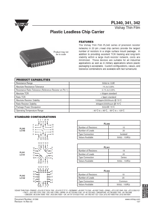
3 2 1 20 19 4 5 6 7 8 9 10 11 12 13 18 17 16 15 14
PL340 Number of Resistors Number of Leads Type Connection Values Available 10 20 Isolated 500Ω - 100KΩ
0.050 inches 4° typical 0.5° typical B1 FP G 4° typical J A, B 0.120” DIAMETER 0.003 - 0.004” DEPTH A1 0.027 inches
Plastic Leadless Chip Carrier
C
D PIN 1 LOCATOR D1
Document Number: 61066 Revision 14-Nov-02
137
元器件交易网
PL340, 341, 342
Vishay Thin Film
PACKAGE OUTLINE DRAWING PLASTIC LEADLESS CHIP CARRIER PL340
138
Document Number: 61066 Revision 14-Nov-02
PL341 LC141
PL342 Number of Resistors Number of Leads Type Connection Values Available 19 20 Common 500Ω - 100KΩ
PL342 LC142
PACKAGED PRODUCTS NETWORKS
ห้องสมุดไป่ตู้
VISHAY THIN FILM • FRANCE +33.4.93.37.28.24 FAX: +33.4.93.37.27.31 • GERMANY +49.9287.710 FAX: +49 9287.70435 • ISRAEL +972.3.557.0945 FAX: +972.3.558.9121 • ITALY + 39.2.300.11919 FAX: +39.2.300.11999 • JAPAN +81.42.729.0661 FAX: +81.42.729.3400 • SINGAPORE +65.788.6668 FAX: +65.788.0988 • SWEDEN +46.8.594.70590 FAX: +46.8.594.70581 • UK +44 191 514 8237 FAX: +44 1953 457 722 • USA: (610) 407-4800 FAX: (610) 640-9081
0.320 0.150 [8.13] [3.81] -----
ORDERING INFORMATION
Example: PL340-20-10-1000-F-F-B-C, 20 Lead PLCC, 1000Ω Isolated Resistors, Absolute Tolerance: 1.0%, Ratio Tolerance: 0.1%, Absolute TCR: 25ppm/°C, Ratio TCR: 2ppm/°C. PL340 20 10 1000 F F B C MODEL NUMBER OF NUMBER OF RESISTANCE ABSOLUTE RATIO ABSOLUTE TCR RATIO TCR LEADS RESISTORS VALUE TOLERANCE TOLERANCE PPM/°C PPM/°C % % (To RREF) The first 3 digits are significant PL341 B = 0.1* D = 0.050* B = 25 C = 2* figures and the last specifies the PL342 C = 0.2* F = 0.100 D = 50 D = 3* number of zeros to follow. D = 0.5 H = 0.250 E = 100 F = 5* “R” designates the decimal F = 1.0 J = 0.500 G = 10 point. G = 2.0 K = 1.000 X = N/A Example: 100 ohms = 1000 J = 5.0 X = N/A 1000 ohms = 1001 K = 10.0 M = 20.0 *Value dependent NOTE: Factory will covert order number into final part number.
Product may not be to scale
PRODUCT CAPABILITIES
Resistance Range Absolute Resistance Tolerance Resistance Ratio Tolerance (Reference Resistor on Pin 1) Absolute TCR Ratio TCR Absolute Resistor Stability Ratio Resistor Stability Package Power Dissipation Operating Temperature Range 500Ω to 100K 1% to 0.05% 0.1% to 0.05% ± 50ppm standard ± 5ppm standard 1000ppm/2000hours @ 70°C 300ppm/2000hours @ 70°C 500mW/ 70°C - 40°C to + 85°C, - 55°C to + 125°C
PACKAGED PRODUCTS NETWORKS
VISHAY THIN FILM • FRANCE +33.4.93.37.28.24 FAX: +33.4.93.37.27.31 • GERMANY +49.9287.710 FAX: +49 9287.70435 • ISRAEL +972.3.557.0945 FAX: +972.3.558.9121 • ITALY + 39.2.300.11919 FAX: +39.2.300.11999 • JAPAN +81.42.729.0661 FAX: +81.42.729.3400 • SINGAPORE +65.788.6668 FAX: +65.788.0988 • SWEDEN +46.8.594.70590 FAX: +46.8.594.70581 • UK +44 191 514 8237 FAX: +44 1953 457 722 • USA: (610) 407-4800 FAX: (610) 640-9081
PL340 LC140
13 12 11 10 9 14 15 16 17 18 19 20 1 2 3
13 12 11 10 9 14 15 16 17 18 19 20 1 2 3 8 7 6 5 4
8 7 6 5 4
PL341 Number of Resistors Number of Leads Type Connection Values Available 19 20 Series 500Ω - 100KΩ
元器件交易网
PL340, 341, 342
Vishay Thin Film
Plastic Leadless Chip Carrier
FEATURES
The Vishay Thin Film PL340 series of precision resistor networks in 20 pin J-lead chip carriers provide the largest number of resistors in a single surface mount package. In addition to providing excellent TCR tracking and long-term stability within a large multi-resistor network, costs are minimized. These devices are suitable for all industrial applications as well as in military applications where plastic packaging is acceptable. Custom configurations, values, and tolerance combinations are available with fast turnaround.
