ASTM E562-02Standard Test Method for Determining Volume Fraction by Systematic Manual Point Count1
astm e1252对应的中文标准

astm e1252对应的中文标准ASTM E1252是美国材料和试验协会(ASTM)发布的关于用光谱法测定金属中残余氢含量的标准。
下面是29句ASTM E1252的双语例句:1. ASTM E1252 provides a standard test method for determining residual hydrogen content in metals using spectroscopic techniques.(ASTM E1252为用光谱法测定金属中残余氢含量提供了一个标准测试方法。
)2. The aim of ASTM E1252 is to ensure accurate and consistent measurement of hydrogen content in metals.(ASTME1252的目的是确保金属中氢含量的准确和一致的测量。
)3. This standard specifies the procedures, equipment and calibrations required for carrying out the hydrogen content measurement.(该标准规定了进行氢含量测量所需的程序、设备和校准要求。
)4. Samples for analysis according to ASTM E1252 should be prepared in a controlled environment to minimize hydrogencontamination.(按照ASTM E1252进行分析的样品应在受控环境中准备,以最小化氢污染。
)5. The test method described in ASTM E1252 is applicable to a wide range of metallic materials.(ASTM E1252中描述的测试方法适用于各种金属材料。
包装材料气味测试标准
包装材料气味测试标准包装材料气味测试是确保产品质量和安全性的一项重要步骤,尤其是对于食品、药品、化妆品等敏感产品。
以下是一些常见的包装材料气味测试标准:1.ISO 12219-3:2019 - Determination of the Emissions ofSemi-Volatile Organic Compounds:•由国际标准化组织(ISO)发布的标准,用于测定半挥发性有机化合物的排放,这些化合物可能导致包装材料产生异味。
2.ASTM E679 - Standard Practice for Determination ofOdor and Taste Thresholds By a Forced-Choice AscendingConcentration Series Method of Limits:•由美国材料和试验协会(ASTM)发布的标准,用于测定气味和味道的阈值,可应用于包装材料的气味评估。
3.DIN 10955 - Testing of plastics; determination of odourby sensory testing (DIN EN 13725):•德国工业标准(DIN)的一部分,通过感官测试来确定塑料材料的气味,该测试方法基于EN 13725标准。
4.CEN/TS 16637 - Packaging - Evaluation of theperformance of a release liner by determination of its behaviourin contact with food stuffs:•由欧洲标准化委员会(CEN)发布的标准,用于评估包装材料与食品接触时的性能,包括气味的影响。
5.GB/T 18885 - Testing method for odor of plasticmaterials in static state:•中国国家标准,用于测定塑料材料在静态状态下的气味,可适用于包装材料的气味测试。
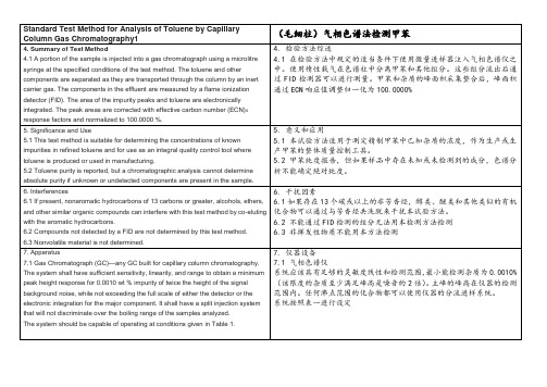
甲苯含量和杂质检测 ASTM D6526 12中英文翻译
8.3 FID Detector Gases:
8.3.1 Hydrogen—99.99 mole % minimum.
8.3.2 Air—less than 10 ppm each of total hydrocarbons andwater.
Polyethylene glycol (PEG) columns have been successfullyused. Other columns may be used after it has beenestablished that such a column is capable of separating allmajor impurities under operating conditions appropriate for the
5. 意义和应用
5.1本试验方法适用于测定精制甲苯中已知杂质的浓度,作为生产或生产甲苯的整体质量控制工具。
5.2甲苯纯度报告,但如果样品中存在未知或未检测到的成分,色谱分析不能确定绝对纯度。
6. Interferences
6.1 If present, nonaromatic hydrocarbons of 13 carbons orgreater, alcohols, ethers, and other similar organic compoundscan interfere with this test method by co-eluting with thearomatic hydrocarbons.
6.2 Compounds not detected by a FID are not determined bythis test method.
加热老化实验的标准

加热老化实验的标准加热老化实验通常用于评估材料、产品或设备在高温环境下长时间使用后的性能稳定性。
有关加热老化实验的标准通常取决于所研究的具体材料或产品类型。
以下是一些可能与加热老化实验相关的常见标准:1.ASTM D573 - Standard Test Method for Rubber—Deterioration in an Air Oven:该标准适用于橡胶材料,描述了在空气烘箱中进行的加热老化实验的程序。
2.ISO 188 - Rubber, vulcanized or thermoplastic —Accelerated ageing and heat resistance tests:这是一个国际标准,适用于橡胶材料的老化和耐热性测试。
3.ASTM D3895 - Standard Test Method for Oxidative-Induction Time of Polyolefins by Differential Scanning Calorimetry:用于聚烯烃(polyolefins)的氧化感应时间测定,该测试方法可以用于评估材料的热老化性能。
4.ASTM E1858 - Standard Test Methods for DeterminingOxidation Induction Time of Hydrocarbons by Differential Scanning Calorimetry:该标准适用于石油产品,描述了使用差示扫描量热仪进行氧化感应时间测定的方法。
5.ASTM G85 - Standard Practice for Modified Salt Spray (Fog)Testing:这是一个通用的耐腐蚀性测试标准,包括高温、湿度和盐雾等条件,适用于金属和涂层的老化性能评估。
6.IEC 60068-2-2 - Environmental testing - Part 2-2: Tests -Test B: Dry heat:该标准是国际电工委员会(IEC)的一部分,涉及干热环境测试的规范。
AATCC 20A 和 ASTM D629 测定纤维成份-显微镜分析
无锡天祥质量技术服务有限公司纺织品测试部AATCC 20A 和 ASTM D629 测定纤维成份(显微镜分析)1.范围1.1.此方法用于两种或以上纤维混合的纺织品,且又无法用机械或化学方法分开的纤维含量的定量分析。
1.2.若样品既含动物纤维又有植物纤维,那么应先用机械方法或化学分析分开。
1.3.此方法依靠技术人员的技术能力用鉴别纤维及对其中各种纤维相对数目进行计数。
1.4.此方法不适用于纵向无特征性状的纤维。
2.参考标准2.1.AATCC Test Method 20A: 2010 纤维定量分析。
2.2.ASTM D629: 2004 纺织品的定量分析。
2.3.ASTM D2130 : 1990(2008) 用显微镜投影方法测量羊毛及其他动物纤维的直径。
2.4.AATCC Test Method 20:2010 纤维定性分析。
3.原理3.1.通过鉴别后计数的方法,某些纤维的混合物,如:棉、大麻、亚麻、苎麻、还有羊毛、骆驼毛、马海毛、羊绒、兔毛及其他有关纤维可通过显微镜鉴别和计数的方法进行定量分析。
再计算出纤维数目的混合百分比。
3.2.为了把这一结果转换成重量百分比,计算中必须包括纤维大小和比重。
4.设备4.1.显微镜,配备图象显示器,放大倍数为50 - 500 。
(用于纤维计数)。
4.2.投影显微镜,放大倍数为 500 (用于纤维测量)。
(见附录I中图 1)。
4.3.精密切片器。
(见附录 I 中图 2 )。
4.4.哈氏切片器。
4.5.单面刀片。
4.6.载玻片,25.4 mm x 76.2 mm / 25 mm x 75 mm。
4.7.盖玻片,22 mm x 22 mm。
4.8.装样试剂-甘油。
4.9.楔形标尺,用于显微镜放大倍数下。
(见附录 I 中图3)。
4.10.分析针。
4.11.火棉胶。
5.取样5.1.机织物5.1.1.准备一块 50 mm x 50 mm 的织物样品。
5.1.2.先计算经纱和纬向的织物密度。
润滑脂检测方法国内外标准对照表
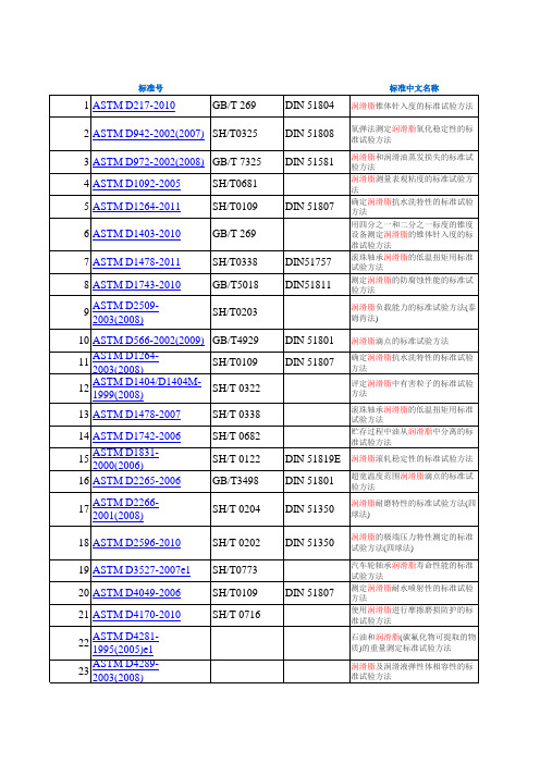
美国测试标准中国测试标准德国测试标准测试项目ASTM D1298GB/T 1884DIN 51757密度ASTM D1500GB/T 6540DIN 51578颜色ASTM D217GB/T 269DIN 51804润滑脂锥入度ASTM D566GB/T 4929DIN 51801润滑脂滴点ASTM 2265GB/T 3498DIN 51801润滑脂宽温滴点ASTM D2783GB/T 3142DIN 51350润滑脂承载能力(PB)(四球法)ASTM D2783GB/T 12583DIN 51350润滑脂极压性(PD)(四球法)ASTM D2782GB/T 11144DIN 51350润滑脂极压性能(梯姆肯法)ASTM D6184SH/T 0324DIN 51817润滑脂分油量(静态法)ASTM D942SH/T 0325DIN 51808润滑脂氧化安定性(双氧弹法)ASTM D217GB/T 269DIN 51804润滑脂机械安定性(剪切法)ASTM D1831SH/T 0122DIN 51819E 润滑脂机械安定性(滚筒法)ASTM D1264SH/T 0109DIN 51807润滑脂抗水淋性ASTM D1092SH/T 0048润滑脂相似粘度ASTM D1743GB/T 5018DIN 51811润滑脂防腐蚀性ASTM D4048GB/T 7326DIN 51759润滑脂铜片腐蚀ASTM D1478SH/T 0338DIN 51757润滑脂低温转矩ASTM D1263SH/T 0326润滑脂轴承漏失量ASTM D3336SH/T 0428DIN 51806润滑脂高温轴承寿命ASTM D972GB/T 7325DIN 51581润滑脂蒸发损失ASTM D471SH/T 0305DIN 53521密封适应性ASTM D877GB/T 507DIN 57370击穿电压ASTM D95GB/T 512DIN 51582水分(蒸馏法)ASTM D92GB/T 267DIN 51376开口闪点ASTM D1404SH/T 0322润滑脂有害粒子鉴定FS791B335.2SH/T 0427润滑脂齿轮磨损ASTM D5483SH/T 0790润滑脂抗氧化性能试验(氧化诱导期)ASTM D2266SH/T 0204抗磨性能(四球机法)磨痕直径 mmDIN 51805润滑脂流动压力测试方法,mbar。
热失重法测定碳纤维复合材料树脂含量对应的标准
热失重法测定碳纤维复合材料树脂含量对应的标准热失重法(Thermogravimetric analysis,TGA)是一种常用的测定材料中某种成分含量的方法,特别是在测定高分子材料中树脂含量时得到广泛应用。
碳纤维复合材料树脂含量测定是工程研究中的一项重要内容,树脂含量的准确测定可以评估材料的质量和性能。
下面介绍一些相关的参考内容,供参考使用。
1. ASTM D4018-20 - Standard Test Methods for Properties of Continuous Filament Carbon and Graphite Fiber Tows该标准规定了测定连续纤维碳纤维和石墨纤维捻线性质的一般试验方法,其中包括测定树脂含量的测试方法。
2. ASTM D2584-16 - Standard Test Method for Ignition Loss of Cured Reinforced Resins该标准规定了测定固化增强树脂的烧失量的测试方法,该方法可用于测定树脂含量。
该测试方法适用于固化树脂含量高于5%的材料。
3. GB/T 22366-2008 碳纤维与树脂基复合材料预测性质测试方法该标准描述了一系列测试方法,用于对碳纤维和树脂基复合材料的性能进行预测。
其中包括测定树脂含量的测试方法。
4. YB/T 5128-2003 碳纤维-树脂复合材料进行热失重法测定碳纤维、纤维树脂含量该标准指定了用热失重法测定碳纤维和树脂含量的测试方法,适用于碳纤维-树脂复合材料的质量控制和产品合格评估。
5. 孟习华, 王生生, 张宏.热失重法测定碳纤维纤维树脂含量的研究[J].耐火材料, 2018(5): 50-52.该文献介绍了用热失重法测定碳纤维复合材料中纤维和树脂含量的研究,提出了一种基于热失重曲线的分析方法,可用于准确测定树脂含量。
除了以上的参考内容,还可以使用相关文献、研究论文等来支撑热失重法测定碳纤维复合材料树脂含量的标准。
高分子材料(塑料)的测试标准(

高分子材料(塑料)的测试标准(ASTM.ISO.GB/T)高分子材料的测试Testing Items Test Requirement邵氏A型硬度Shore Type A HardnessASTM D2240-05ISO 7619-97GB/T 2411-1980(1989)邵氏D型硬度Shore Type D HardnessASTM D2240-05ISO 7619-973GB/T 2411-1980(1989)洛氏硬度 Rockwell HardnessASTM D785-03ISO 2039-2:1987GB/T 9342-88拉伸强度(模塑料,原料) Tensile Strength (Mould Plastic& Materials)ASTM D638-039ISO 527-2:1993GB/T 1040-92ASTM D412-1998a(2002)e1 (橡胶)ISO 37-2005(橡胶)GB/T 528-1998(橡胶)拉伸强度(膜材与片材) Tensile Strength(Plastic Sheet & Film)ASTM D882-02 (单方向)GB/T 13022-1991 (单方向)ASTM D882-02 (MD/CD)ISO 527-3:1995 (MD/CD)GB/T 13022-1991 (MD/CD)拉伸强度(编织袋)Tensile Strength(Braided tapes )ISO 10371-1993(单方向)GB/T 8946-1998(单方向)GB/T 10454-2000(单方向)ISO 10371-1993(MD/CD)GB/T 8946-1998(MD/CD)GB/T 10454-2000(MD/CD)断裂伸长率(模塑料、原料) Elongation at break(Mould Plastic& Materials) ASTM D638-038ISO 527-2:1993ASTM D412-1998a(2002)e1 (橡胶)ISO 37-2005(橡胶)GB/T 528-1998(橡胶)断裂伸长率(膜材与片材)Elongation at break(Plastic Sheet & Film) ASTM D882-02 (单方向)ISO 527-3:1995 (单方向)GB/T 13022-1991 (单方向)ASTM D882-02 (MD/CD)ISO 527-3:1995 (MD/CD)GB/T 13022-1991 (MD/CD)拉伸模量(模塑料、原料) Tensile Modulus(Mould Plastic& Materials) ASTM D638-03ISO 527-2:1993GB/T 1040-92拉伸模量(膜材与片材)Elongation at break(Plastic Sheet & Film)) ASTM D882-02 (单方向)ISO 527-3:1995 (单方向)GB/T 13022-1991 (单方向)ASTM D882-02 (MD/CD)ISO 527-3:1995 (MD/CD)GB/T 13022-1991 (MD/CD)弯曲强度Flexural ASTM D790-03ISO 178:2001GB/T 9341-2000弯曲模量Flexural modulusASTM D790-032ISO 178:20014GB/T 9341-2000悬臂梁冲击强度IZOD Impact StrengthASTM D256-05(有缺口)ASTM D4812-1999(无缺口)ISO 180:2000GB/T 1843-96简支梁冲击强度CHARPY Impact StrengthASTM D6110-04ISO 179-2:1997撕裂强度(膜材与片材)Tearing strength(Plastic Sheet & Film)ASTM D1004-03 (单方向)ASTM D1938-02 (单方向)ISO 6383-1:1983 (单方向)GB/T 16578-96 (单方向)ASTM D1004-03 (MD/CD)ASTM D1938-02 (MD/CD)ISO 6383-1:1983 (MD/CD)GB/T 16578-96 (MD/CD)ASTM D624-00e1(橡胶)ISO 34-1:1994(橡胶)GB/T 529-1999(橡胶)剥离强度Peeling strengthASTM D5458-95(2001)(复合膜)穿刺强度Puncture StrengthASTM D4833-00压缩强度 Compression StrengthASTM D695-02ISO 604-02GB/T 1041-92压缩模量 Compression ModulusASTM D695-02aISO 604-02GB/T 1041-925压缩变形Compression SetASTM D395-03(弹性体)ASTM D395-03(橡胶)GB/T 7759-1996(橡胶)ISO 815(橡胶)薄膜摆锤冲击强度Tear Resistance of Film & Sheet by Pendulum Method ASTM D1922-03 (单方向)ASTM D1922-03 (MD/CD)- M8落锤冲击强度 Falling Weight Impact StrengthASTM D5628-96(2001)ASTM D4226-2000(PVC建材)ASTM D5420-04(Gardner Impact)GB/T 11548-89(板材)GB/T 14153-93(硬质塑料)薄膜落镖冲击强度Impact Resistance of Plastic Film by the Free-Falling Dart ASTM D1709-03GB/T 9639-1988塑胶及弹性体脆化温度Brittleness Temperature of PlasticsElastomers by Impact ASTM D746-04(需指定温度)薄膜脆化温度Brittleness Temperature of Plastic Sheeting by ImpactASTM D1790-02(薄膜)需指定温度点GB/T 11999-1989需指定温度点ASTM D1790-02(薄膜)未指定温度点GB/T 11999-1989 未指定温度点薄膜与片材动静态磨擦系数Statickinetic Coefficient of Friction of FilmSheet ASTM D1894-01ISO 8295-950 W$ \+ J- p0 M( N3 l. rGB 10006-88模具收缩率Mould ShrinkageASTM D955-00磨耗性能(Taber) Taber Abrasion Resistance(需指定转数,磨轮,重量)ASTM D1044-99ASTM D4060-01ISO 9352:1995密度DensityASTM D792-00ISO 1183-1:2004GB/T 1033-86ASTM D1622-03 (硬质泡沫表观密度)ASTM D3574-03(软质泡沫表观密度)GB/T 6343-95 (泡沫表观密度)尺寸SizeASTM D5947-03ISO 4648-91GB/T 5723-93面积重Mass per Unit AreaASTM D5261-92(2003)热学测试ASTM D1238-04 Melt-Mass Flow Rate (MFR) 质量流动速率ISO 1133:1997 Melt-Mass Flow Rate (MFR) 质量流动速率GB/T 3682-2000 Melt-Mass Flow Rate (MFR) 质量流动速率ASTM D1238-04 Melt V olume-Flow Rate (MVR) 体积流动速率ISO 1133:1997 Melt Volume-Flow Rate (MVR) 体积流动速率GB/T 3682-2000 Melt Volume-Flow Rate (MVR) 体积流动速率ASTM D648-04 Deflection Temperature of Plastics 热变形温度ISO 75-2:2004 Deflection Temperature of Plastics 热变形温度GB/T 1634.1-2004 Deflection Temperature of Plastics 热变形温度ASTM D1525-00 Vicat Softening Temperature of Plastics 维卡软化点ISO 306:2004 Vicat Softening Temperature of Plastics 维卡软化点GB/T 1633-2000 Vicat Softening Temperature of Plastics 维卡软化点ASTM D3850-94(2000) Solid Electrical Insulating Materials 热失重温度ASTM D6370-99(2003) Rubber-Compositional Analysis 热失重温度GB/T19466.2-2004 玻璃化转变温度ISO11357:1999 玻璃化转变温度GB/T19466.3-2004 熔点ISO11357:1999 熔点GB/T19466.3-2004 Crystallization Temperature 结晶温度ISO11357:1999 Crystallization Temperature 结晶温度DSC法Heat of Crystallization 结晶热DSC法Heat of Fusion 熔融热ASTM D696-03 热膨胀系数coefficient of thermal expansionASTM D3386-2000 热膨胀系数coefficient of thermal expansionASTM DE831-03 热膨胀系数coefficient of thermal expansionISO 8301-91 热抟导系数Thermal Conduction CoefficientASTM C518-02e1 热抟导系数Thermal Conduction CoefficientASTM C177-97 热抟导系数Thermal Conduction CoefficientPVC热稳定GB 2917-88 PVC类聚合物热稳定性试验Thermal Stable property of PVC ISO 305-90 PVC类聚合物热稳定性试验Thermal Stable property of PVCISO 182/1-4-90 PVC类聚合物热稳定性试验Thermal Stable property of PVCPEPP热稳定ISO 4577-83 PE,PP热稳定性试验Thermal Stable property of PE,PP不饱和聚酯GB 7193.5-87 Thermal Stable property of Unsaturated PolyesterGB 7193.5-87 不饱和聚酯热稳定性试验。
国外主要无损检测标准含中英文名称对照
ASTM A 754/A 754M-1996X射线荧光法测量涂层厚度的试验方法Test Method for Coating Thickness by X-Ray FluorescenceASTM B567-1998用B射线背散射法测量涂层厚度的试验方法Test Method for Measurement of Coating Thickness by the Beta Backscatter MethodASTM B568-1998X射线光谱仪法测量涂层厚度的试验方法Test Method for Measurement of Coating Thickness by X-Ray SpectrometryASTM C637-1998辐射屏蔽混凝土用集料的标准规范Standard Specification for Aggregates for Radiation-Shielding ConcreteASTM C638-1992辐射屏蔽混凝土集料组分的描述术语Descriptive Nomenclature of Constituents of Aggregates for Radiation-Shielding Concrete ASTM C1455-2000用Y射线谱法无损检定仍然有效特殊核材料指南ASTM D2599-1987X射线光谱法测定汽油含铅量的试验方法(05.02)Test Method for Lead in Gasoline by X-Ray Spectrometry (05.02)ASTM D4294-1998用非色散X射线荧光光谱法测定石油产品中含硫量试验方法Sulfur in Petroleum Products by Non-Dispersive X-Ray Fluorescence Spectrometry, Method of Test for (05.02)ASTM D4452-1985 土壤样品的X 射线照相法X-Ray Radiography of Soil SamplesASTM D5059-1998X-射线光谱法测定汽油含铅量的试验方法Test Method for Lead in Gasoline by X-Ray Spectroscopy (05.03)ASTM D5187-1991X射线衍射法测定煅烧石油焦炭中结晶尺寸(LC)的试验方法Test Method for Crystallite Size (LC) of Calcined Petroleum Coke by X-Ray Diffraction (05.03) ASTM D6247-1998X射线荧光光谱法分析聚烯烃中元素含量的试验方法Test Method for Analysis of Elemental Content in Polyolefins by X-Ray Fluorescence SpectrometryASTM E94-2004(2010)射线照相检验标准指南Standard Guide for Radiographic Examination ASTM E142-1996 射线照相检测的质量控制方法Method for Controlling Quality of Radiographic TestingASTM E155-2010铝镁合金铸件射线照相检验标准参考照片Standard Reference Radiographs for Inspection of Aluminum and Magnesium CastingsASTM E170-1999有关辐射测量和剂量测定的术语ASTM E181-1998放射性核素探测器的校准和分析的一般方法General Methods for Detector Calibration and Analysis of RadionuclidesASTM E186-2010厚壁(50.8-114mm)钢铸件标准参考射线照片Standard Reference Radiographs for Heavy-Walled (2 to 4 1/2-In./50.8 to 114-mm) Steel Castings ASTM E192-2004(2010)e1宇航用熔模钢铸件标准参考射线照片Standard Reference Radiographs for Investment Steel Castings of AerospaceApplicationsASTM E242-2001(2010)某些参数改变时射线照相图象显示的标准参考射线照片Standard Reference Radiographs for Appearances of Radiographic Images asCertain Parameters Are ChangedASTM E272-2010高强度铜基及镍铜合金铸件的标准参考射线照片Standard Reference Radiographs for High-Strength Copper-Base andNickel-Copper Alloy CastingsASTM E280-2010厚壁(114-305mm)铸钢件标准参考射线照片Standard Reference Radiographs for Heavy-Walled (4 1/2 to 12-in. (114 to305-mm)) Steel CastingsASTM E310-2010锡青铜铸件标准参考射线照片Standard Reference Radiographs for Tin Bronze CastingsASTM E390-2011钢熔焊焊缝标准参考射线照片Standard Reference Radiographs for Steel Fusion WeldsASTM E431-96(2011)半导体和相关器件射线照片判读指南Standard Guide to Interpretation of Radiographs of Semiconductors andRelated DevicesASTM E446-2010厚度至50.8mm钢铸件的标准参考射线照片Standard Reference Radiographs for Steel Castings up to 2 in. (50.8 mm) inThicknessASTM E505-2001(2011)铝和镁压铸件检验的标准参考射线照片Standard Reference Radiographs for Inspection of Aluminum and Magnesium Die Castings ASTM E545-2005(2010)确定直接热中子射线照相检验成象质量的标准试验方法Standard Test Method for Determining Image Quality in Direct ThermalNeutron Radiographic ExaminationASTM E586-88Y与X射线照相检测的术语定义ASTM E592-1999(2009)e16〜51mm厚钢板X射线照相检验和25〜152mm厚钢板钻60照相检验获得ASTM当量穿透灵敏度的标准指南Standard Guide to Obtainable ASTM Equivalent Penetrameter Sensitivity forRadiography of Steel Plates 1/4 to 2 in. (6 to 51 mm) Thick with X Rays and 1 to 6 in. (25 to 152 mm) Thick with Cobalt-60ASTM E665-1994测量暴露在X闪光射线机的X射线照射下的材料中相对深度的吸收剂量Determining Absorbed Dose Versus Depth in Materials Exposed to the X-RayOutput of Flash X-Ray MachinesASTM E666-1997Y 或X 射线剂量吸收的计算Calculating Absorbed Dose from Gamma or X RadiationASTM E689-2010球墨铸铁标准参考射线照片Standard Reference Radiographs for Ductile Iron CastingsASTM E746-2007测定工业射线照相成像系统相关图象质量响应的标准方法Standard Practice for Determining Relative Image Quality Response ofIndustrial Radiographic Imaging SystemsASTM E747-2004(2010)射线照相用线型象质计(IQI)的设计、制造及材料组分类的标准方法Standard Practice for Design, Manufacture, and Material GroupingClassification of Wire Image Quality Indicators (Iqi) Used for RadiologyASTM E748-2002(2008)材料热中子射线照相标准方法Standard Practices for Thermal Neutron Radiography of MaterialsASTM E801-2006(2011)电子装置射线照相检验的质量控制标准方法Standard Practice for Controlling Quality of Radiological Examination of Electronic Devices ASTM E802-1995(2010)厚度至114mm的灰口铸铁标准参考射线照片Standard Reference Radiographs for Gray Iron Castings up to 4 1/2 in. (114 mm) in ThicknessASTM E803-1991(2008)确定中子射线透照束长径比的标准方法Standard Method for Determining the L/D Ratio of Neutron Radiography BeamsASTM E915-1996残余应力测量用X射线衍射仪校准检定的试验方法Test Method for Verifying the Alignment of X-Ray DiffractionInstrumentation for Residual Stress MeasurementASTM E999-2010工业射线照相胶片处理的质量控制标准指南Standard Guide for Controlling the Quality of Industrial Radiographic FilmProcessingASTM E1000-98(2009)射线照相检测标准指南Standard Guide for RadioscopyASTM E1025-2011射线照相检测用孔型象质计设计、制造和材料组分类的标准方法Standard Practice for Design, Manufacture, and Material GroupingClassification of Hole-Type Image Quality Indicators(IQI) Used forRadiographyASTM E1030-2005(2011)金属铸件射线照相检验的标准试验方法Standard Test Method for Radiographic Examination of Metallic CastingsASTM E1032-2012焊缝射线照相检验的标准试验方法Standard Test Method for Radiographic Examination of WeldmentsASTM E1079-2010透射密度计校准的标准方法Standard Practice for Calibration of Transmission DensitometersASTM E1114-2009e1测定铱192工业射线照相源尺寸的标准试验方法Standard Test Method for Determining the Size of Iridium -192 IndustrialRadiopraphic SourcesASTM E1161-2009半导体和电子元件射线检验的标准方法Standard Practice for Radiologic Examination of Semiconductors andElectronic ComponentsASTM E1165-2004(2010)用针孔成象法测量工业X射线管焦点的标准试验方法Standard Test Method for Measurement of Focal Spots of Industrial X-RayTubes by Pinhole ImagingASTM E1168-1995 核设施工人辐射防护训练Radiological Protection Training for Nuclear Facility WorkersASTM E1254-2008射线照片及未曝光工业射线照相胶片储藏的标准指南Standard Guide for Storage of Radiographs and Unexposed IndustrialRadiographic FilmsASTM E1255-2009射线透视检验标准方法Standard Practice for RadioscopyASTM E1320-2010钛铸件标准参考射线照片Standard Reference Radiographs for Titanium CastingsASTM E1390-2012工业射线照相观片灯标准规范Standard Specification for Illuminators Used for Viewing IndustrialRadiographsASTM E1400-1995高剂量辐射量测定校准实验室的特性和性能规程Characterization and Performance of a High-Dose Radiation DosimetryCalibration Laboratory, Practice for (12.02)ASTM E1411-2009射线照相系统鉴定的标准方法Standard Practice for Qualification of Radioscopic SystemsASTM E1416-2009 焊缝射线检验的标准试验方法Standard Test Method for Radioscopic Examination of WeldmentsASTM E1441-2011计算机层析(CT)成像的标准指南Standard Guide for Computed Tomography (CT) ImagingASTM E1441-2000 计算机层析成像(CT)指南Guide for Computed Tomography (CT) Imaging ASTM E1453-2009含模拟或数字射线照相数据的磁带媒体存储标准指南Standard Guide for Storage of Magnetic Tape Media that Contains Analog orDigital Radioscopic DataASTM E1475-2002(2008)数字射线照相检验数据计算机化传输的数据区标准指南Standard Guide for Data Fields for Computerized Transfer of DigitalRadiological Examination DataASTM E1496-2005(2010)中子射线照相尺寸测量的标准试验方法Standard Test Method for Neutron Radiographic DimensionalMeasurements(With drawn 2012)ASTM E1570-2011计算机层析(CT)检验标准方法Standard Practice for Computed Tomographic (CT) ExaminationASTM E1647-2009确定射线照相检测对比度灵敏度的标准方法Standard Practice for Determining Contrast Sensitivity in RadiologyASTM E1648-1995(2011)铝熔焊焊缝检验标准参考射线照片Standard Reference Radiographs for Examination of Aluminum Fusion WeldsASTM E1672-2006选择计算机层析(CT)系统的标准指南Standard Guide for Computed Tomography (Ct) System SelectionASTM E1695-1995(2006)e1计算机层析(CT)系统性能测量的标准试验方法Standard Test Method for Measurement of Computed Tomography (Ct) System PerformanceASTM E1734-2009铸件射线照相检验标准方法Standard Practice for Radioscopic Examination of CastingsASTM E1735-2007确定经4-25MV X射线曝光的工业射线胶片相关成像质量的标准试验方法Standard Test Method for Determining Relative Image Quality of IndustrialRadiographic Film Exposed to X-Radiation from 4 to 25 MVASTM E174〃E1742M-2011射线照相检验标准方法Standard Practice for Radiographic ExaminationASTM E1814-1996(2007)铸件计算机层析(CT)检验标准方法Standard Practice for Computed Tomographic (CT) Examination of CastingsASTM E1815-2008工业射线照相胶片系统分类的标准试验方法Standard Test Method for Classification of Film Systems for IndustrialRadiographyASTM E1817-2008使用典型象质计(RQIs)控制射线检验质量的标准方法Standard Practice for Controlling Quality of Radiological Examination byUsing Representative Quality Indicators(RQI-s)ASTM E1894-1997选择脉冲X射线源用的剂量测定系统的标准指南Standard Guide for Selecting Dosimetry Systems for Application in PulsedX-Ray SourcesASTM E1931-2009X射线康普顿散射层析技术标准指南Standard Guide for X-ray Compton Scatter TomographyASTM E1935-1997(2008)校准和测量计算机层析(CT)密度的标准试验方法Standard Test Method for Calibrating and Meausring CT DensityASTM E1936-2003(2011)评估射线照相数字化系统性能的标准参考射线照片Standard Reference Radiograph for Evaluating the Performance ofRadiographic Digitization SystemsASTM E1955-2004(2009)与美国材料与试验协会ASTM E 390参考射线照片等级比较钢中焊缝完善性的标准射线检验Standard Radiographic Examination for Soundness of Welds in Steel byComparison to Graded ASTM E390 Reference RadiographsASTM E2002-1998(2009)测定射线照相图象总不清晰度的标准方法Standard Practice for Determining Total Image Unsharpness in RadiologyASTM E2003-2010中子射线照相波束纯度指示计制作的标准方法Standard Practice for Fabrication of the Neutron Radiographic Beam PurityIndicators [Metric]ASTM E2007-2010计算机射线照相标准指南(用于CR的标准指南)(可激射线发光[PSL]法)Standard Guide for Computed Radiology (Photostimulable Luminescence (PSL)Method)ASTM E2023-2010制作中子射线照相灵敏度指示计的标准方法Standard Practice for Fabrication of Neutron Radiographic SensitivityIndicatorASTM E2033-1999(2006)计算机射线照相的标准方法(用于CR的标准实施方法)(可激射线发光晓1]法)Standard Practice for Computed Radiology (Photostimulable LuminescenceMethod)ASTM E2104-2009优质航空与涡轮材料和构件射线照相检验的标准方法Standard Practice for Radiographic Examination of Advanced Aero andTurbine Materials and ComponentsASTM E2120-2000便携式X射线荧光光谱仪测量涂膜中铅含量的性能评估规程Practice for the Performance Evaluation of the Portable X-Ray FluorescenceSpectrometer for the Measurement of Lead in Paint FilmsASTM E2339-2004无损评价中的数字成像和通讯Digital Imaging and Communication in NDE(DICONDE)ASTM E2422-2011铝铸件标准参考数字射线图像(钛和钢铸件也适用)Standard Digital Reference Images for Al. Casting(Titanium & steel Casting also available) ASTM E2445-2005(2010)计算机射线照相系统的长期稳定性与鉴定的标准方法(用于CR系统的质量认定和长期稳定性的标准实施方法)Standard Practice for Qualification and Long-Term Stability of ComputedRadiology SystemsASTM E2446-2005(2010)计算机射线照相系统分类的标准方法(用于CR系统分类的标准实施方法)Standard Practice for Classification of Computed Radiology SystemsASTM E2597-2007e1数字探测器阵列制造特性的标准规程Standard Practice for Manufacturing Characterization of Digital DetectorArraysASTM E2660-2011航空用优质钢铸件标准参考数字射线图像Standard Digital Reference Images for Investment Steel Castings forAerospace ApplicationsASTM E2662-2009航空用平面与夹芯复合材料射线照相检验的标准方法Standard Practice for Radiologic Examination of Flat Panel Composites andSandwich Core Materials Used in Aerospace ApplicationsASTM E2669-2011数字射线照相(DR)检测方法的数字图像与通信无损评价(DICONDE)的标准方法Standard Practice for Digital Imaging and Communication in NondestructiveEvaluation (DICONDE) for Digital Radiographic (DR) Test MethodsASTM E2698-2010使用数字探测器阵列的射线照相检验标准方法Standard Practice for Radiological Examination Using Digital DetectorArraysASTM E2736-2010数字探测器阵列射线照相检测标准指南Standard Guide for Digital Detector Array RadiologyASTM E2737-2010评价数字探测器阵列性能和长期稳定性的标准方法Standard Practice for Digital Detector Array Performance Evaluation andLong-Term StabilityASTM E2738-2011使用计算机射线照相(CR)检测方法的数字图像与通讯无损评价(DICONDE) 的标准方法Standard Practice for Digital Imaging and Communication NondestructiveEvaluation (DICONDE) for Computed Radiography (CR) Test MethodsASTM E2767-2011使用X射线计算机层析(CT)检测方法的数字图像与通讯无损评价(DICONDE)的标准方法Standard Practice for Digital Imaging and Communication in NondestructiveEvaluation (DICONDE) for X-ray Computed Tomography (CT) Test MethodsASTM E2861-2011测量中子辐射束发散与校准的标准试验方法Standard Test Method for Measurement of Beam Divergence and Alignment inNeutron Radiologic BeamsASTM F629-1997铸造金属外科手术植入物射线照相检查实施方法(14)ASTM F727-1981透明照相干版透光度测量的试验方法Test Method for Measuring Transmittance of See-Through PhotoplateASTM F784-1982校准放射性同位素密封测试仪的试验方法Test Method for Calibrating Radioisotope Hermetic Test ApparatusASTM F864-1984 硬表面玻璃照相干板的检验Inspection of Hard-Surface Glass Photoplates ASTM F947-1985测定照相胶片低能级X射线辐射灵敏度的试验方法Test Method for Determining Low-Level X-Radiation Sensitivity ofPhotographic FilmsASTM F1035-1991使用橡胶帘布圆盘验证轮胎X射线成象系统的辩别能力Use of Rubber-Cord Pie Disk to Demonstrate the Discernment Capability of aTire X-Ray Imaging SystemASTM F1039-1987X射线安全屏系统中测量低剂量X辐射的试验方法Test Method for Measurement of Low Level X-Radiation Used in X-RaySecurity Screening SystemsASTM F1467-1999微电子装置电离辐射效应中X射线测试仪(近似等于10keV辐射量子)的使用Use of an X-Ray Tester (is Approximately Equal to 10 keV Photons) inIonizing Radiation Effects Testing of Microelectronic DevicesASTM PS95-1998便携式X射线荧光(XRF)装置现场测定涂料或其它涂层含铅量的质量体系的标准临时操作规程Standard Provisional Practice for Quality Systems for Conducting In SituMeasurements of Lead Content in Paint or Other Coatings usingField-Portable X-Ray Fluorescence (XRF) DevicesASTM PS 116-1999测量涂膜含铅量用的便携式X射线荧光光谱仪性能评价的临时操作规程Provisional Practice for the Performance Evaluation of the Portable X-RayFluorescence Spectrometer for the Measurement of Lead in Paint FilmsANSI/ANS6.1.1-1991中子及r射线对剂量因素的影响Neutron and Gamma-Ray Fluence-to-DoseFactorsANSI/IEEE 309-1970 盖革-弥勒计数器的试验程序Geiger-Muller Counters, Test Procedure for ANSI IT9.2-1991成象介质-已处理的照相胶片、平板和相纸-归档盒及储存箱Imaging Media - Photographic Processed Films, Plates and Papers - FilingEnclosures and Storage ContainersANSI IT9.8-1989成象介质-照相胶片耐折强度的测定Imaging Media - Photographic Film - Determination of Folding EnduranceANSI N13.2-1969 辐射监测的管理规程指南Administrative Practices in Radiation Monitoring, Guide toANSI N13.5-1972直读和非直读式袖珍X和Y射线辐射剂量仪的性能Direct Reading and Indirect Reading Pocket Dosimeters for X- and GammaRadiation, PerformanceANSI N13.7-1983辐射防护照相胶片剂量仪性能标准Radiation Protection - Photographic Film Dosimeters - Criteria forPerformanceANSI N13.11-2001 个人剂量测定的试验标准Personnel Dosimetry Performance, Criteria for TestingANSI N13.27-1981袖珍式报警辐射剂量仪和报警记数率计的性能要求Performance Requirements for Pocket-Sized Alarm Dosimeters and AlarmRatemetersANSI N15.36-1994核材料无损化验测量的控制和保证Nuclear materials - Nondestructive assay measurement control and assuranceANSI N15.37-1981核材料控制的自动无损化验系统指南Automation of Nondestructive Assay Systems for Nuclear Materials Control,Guide toANSI N42.16-1986用于液体闪烁计数器的密封放射检查源的规范Specifications for sealed radioactive check sources used in liquid-scintillation countersANSI N42.20-1995 个人辐射监视仪的性能标准Performance criteria for active personnel radiation monitorsANSI N42.26-1995辐射防护仪器监测设备X和Y辐射个人报警装置Radiation Protection Instrumentation - Monitoring Equipment - PersonalWarning Devices for X and Gamma RadiationsANSI N43.3-1993通用辐射安全非医疗应用的X射线和密封Y射线源的安装能量达10Mev General radiation safety - Installations using non-medical X-ray andsealed gamma-ray sources, energies up to 10 MeVANSI N43.6-1997 密封放射性源的分类Classification of Sealed Radioactive SourcesANSI N43.9-1991Y射线照相仪器的设计和试验规范Gamma Radiography - Specifications for Design and Testing of ApparatusANSI N322-1996直接和间接读取石英纤维袖珍剂量计的检验和试验规范Inspection and Test Specifications for Direct and Indirect Reading QuartzFiber Pocket DosimetersASME Boiler & Pressure VesselCode(ASME锅炉压力容器规范)第V卷《无损检测》2004版,第2篇“射线检测”,强制性附录-包含动态射线照相、实时射线成像检测内容ASME SE-1647确定射线照相对比灵敏度的推荐实施方法ASME Code Case 2476使用荧光成像板的射线照相Radiography using phosphor imaging platesMIL-HDBK-55-66射线照相无损检测手册(已由MIL-HDBK-7285取代)MIL-STD-139A-65射线检测铝镁合金铸件的完好性要求MIL-STD-453C-88射线照相检测MIL-STD-746A-63铸造爆破器材的射线照相检测要求MIL-STD-779-68钢焊缝参考X射线照片(由ASTM E390取代)MIL-STD-1257A-87钻铬合金枪管射线照相及目视检验MIL-R-11470A-71对射线检验设备,操作方法和操作人员的合格审查(由MIL-STD-453取代) MIL-I-36013B-72折迭式X射线观片灯MIL-R-45226-62石墨的射线照相检测(已停用)MIL-R-45774A(92)铝,镁导弹零件熔焊完好性要求-射线照相检测MIL-STD-1948(91)中子射线照相检验的术语和定义汇编MIL-HDBK-7285(92)射线照相检验MIL-HDBK-733(92)复合材料无损检验方法-射线照相法MIL-STD-1166A(91)固体火箭推进剂射线照相检验要求MIL-STD-1264B(93)钢焊缝完好性射线照相检验-与ASTM E390各级参考底片比较MIL-STD-1265A(92)钢铸件射线照相检验分类和完好性要求MIL-STD-1894A(86)不完全焊透钢焊缝的射线照相参考标准及射线照相程序MIL-STD-1895A(86)不完全焊透铝焊缝的射线照相参考标准及射线照相程序BAC 5915(美国波音公司)射线检验DPS 4.736(美国麦道公司) 射线检验API 1104(美国石油协会)管道及有关设备的焊接AWS B 5.15射线照相评片资格技术条件。
第二课松香酸值的标准测定方法解析

New words and expressions
rosin acid number internal indicator method potentiometric method glass electrode alkali isopropanol
松香,树脂 酸值 内指示剂法 电位(势) 玻璃电极 碱 异丙醇
名称,指定 权限 声称 块 碾,磨 滴定 滴定管
Designation:D465-82 (Reapproved 1997)1
This standard is issued under the fixed designation D 465: the number immediately followed the designation indicate the year of original adoption or, in the case of revision, the year of last revision. A number in parentheses indicates the year 上标 圆括号 of last reapproval. A superscript epsilon (ε) indicates an editorial change since the last revision or reapproval. 1Note: Section 7 was changed editorially in November 1987.
New words and expressions
buffer beaker volumetric flask buret inflection point
缓冲液 烧杯 容量瓶 滴定管 拐点
New words and expressions
AATCC 20A 和 ASTM D629 测定纤维成份-显微镜分析
无锡天祥质量技术服务有限公司纺织品测试部AATCC 20A 和 ASTM D629 测定纤维成份(显微镜分析)1.范围1.1.此方法用于两种或以上纤维混合的纺织品,且又无法用机械或化学方法分开的纤维含量的定量分析。
1.2.若样品既含动物纤维又有植物纤维,那么应先用机械方法或化学分析分开。
1.3.此方法依靠技术人员的技术能力用鉴别纤维及对其中各种纤维相对数目进行计数。
1.4.此方法不适用于纵向无特征性状的纤维。
2.参考标准2.1.AATCC Test Method 20A: 2010 纤维定量分析。
2.2.ASTM D629: 2004 纺织品的定量分析。
2.3.ASTM D2130 : 1990(2008) 用显微镜投影方法测量羊毛及其他动物纤维的直径。
2.4.AATCC Test Method 20:2010 纤维定性分析。
3.原理3.1.通过鉴别后计数的方法,某些纤维的混合物,如:棉、大麻、亚麻、苎麻、还有羊毛、骆驼毛、马海毛、羊绒、兔毛及其他有关纤维可通过显微镜鉴别和计数的方法进行定量分析。
再计算出纤维数目的混合百分比。
3.2.为了把这一结果转换成重量百分比,计算中必须包括纤维大小和比重。
4.设备4.1.显微镜,配备图象显示器,放大倍数为50 - 500 。
(用于纤维计数)。
4.2.投影显微镜,放大倍数为 500 (用于纤维测量)。
(见附录I中图 1)。
4.3.精密切片器。
(见附录 I 中图 2 )。
4.4.哈氏切片器。
4.5.单面刀片。
4.6.载玻片,25.4 mm x 76.2 mm / 25 mm x 75 mm。
4.7.盖玻片,22 mm x 22 mm。
4.8.装样试剂-甘油。
4.9.楔形标尺,用于显微镜放大倍数下。
(见附录 I 中图3)。
4.10.分析针。
4.11.火棉胶。
5.取样5.1.机织物5.1.1.准备一块 50 mm x 50 mm 的织物样品。
5.1.2.先计算经纱和纬向的织物密度。
ASTM A262-02中文翻译
检测奥氏体不锈钢晶间腐蚀敏感度的标准实施规范这个标准是在修改已有的A262后出版的,里面的数字说明的是原来版本的年份或者上个修订版的年份。
括号中的数字说明的是标准上次通过的年份。
上标数字ε表明的是上次修订或者通过的编辑的变化。
这部标准已经批准被国防部使用。
ε1 注释:表1是在2004年8月编辑校正的。
ε2 注释:30.1.5.1是在2005年1月编辑校正的。
ε3 注释:1.5和7.4节2005年7月编辑校正。
1. 范围1.1这个规范涵盖了以下五个试验:1.1.1试验A——奥氏体不锈钢的腐蚀结构分类的草酸腐蚀试验(包括从第3节到第7节)1.1.2试验B——检测奥氏体不锈钢晶间腐蚀敏感度的硫酸铁-硫酸试验(包括从第8节到第14节)1.1.3试验C——检测奥氏体不锈钢晶间腐蚀敏感度的硝酸试验(包括从第15节到第21节)1.1.4试验E——检测奥氏体不锈钢晶间腐蚀敏感度的铜-硫酸铜-硫酸试验(包括从第22节到第31节)1.1.5试验F——检测奥氏体不锈钢晶间腐蚀敏感度的铜-硫酸铜-50%硫酸试验(包括从第32节到第38节)1.2以下因素制约制约着这个规范:1.2.1所有的六个检测都要检测碳铬化物晶间腐蚀感度1.2.2铬镍钼钢中的σ相在硝酸中可导致高腐蚀速率,σ相在微观结构中也不一定可见。
1.2.3在钛或铌合金和钼合金轴承钢中的σ相在硝酸和硫酸铁-硫酸溶液中会有高腐蚀速率,铸铁轴承不锈钢合金,这种σ相在微观结构中也不一定可见。
1.3草酸腐蚀试验是一种快速的确定不锈钢试样的等级方法,这种牌号的不锈钢不会产生碳铬化合物的晶间腐蚀。
在特定的腐蚀测试条件下,这种试样腐蚀速率低,因此可以从实验中排除看是否可接受的。
1.4硫酸铁-硫酸试验,铜-硫酸铜-50%硫酸的试验,以及硝酸测试这些实验以重量减少为基础,从而为相关的试样评估提供了一个定量方法。
相反,铜-硫酸铜-16%硫酸试验主要对弯曲试样进行表观检查,因此只能确定试样是否合格。
第二课松香酸值的标准测定方法
① 标准试验方法(Standard Test Method):它是为鉴定、检测和评估材料、产品、 系统或服务的质量、特性及参数等指标而采用的规定程序。
② 标准规范(Standard Specification) 它对材料、产品、系统,或项目提出技术 要求并给出具体说明,同时还提出了满足技术要求而应采用的程序。
This standard is issued under the fixed designation D 465: the
number immediately followed the designation indicate the
year of original adoption or, in the case of revision, the year
normality stirring paddle
当量浓度 搅拌浆
standardization
标准化
borax
硼砂
New words and expressions
buffer beaker volumetric flask buret inflection point
缓冲液 烧杯 容量瓶 滴定管 拐点
potentiometric method 电位(势)
glass electrode
玻璃电极
alkali
碱
isopropanol
异丙醇
New words and expressions
phenolphthalein
酚酞
thymol blue
百里酚蓝
erlenmeyer flask 厄伦美厄烧瓶(三角瓶)
of lasttheses indicates the year
astm d6352对应中文标准 -回复
astm d6352对应中文标准-回复ASTM D6352是一项与天然气和液化石油气产业相关的标准,为液化石油气(LPG)和天然气(NG)的取样和分析提供了指导。
该标准由美国材料和测试协会(ASTM International)制定,其全称为ASTMD6352-00(2017),标题为"Standard Practice for Sampling Liquefied Petroleum (LP) Gases, Manual Method",翻译为中文为"液化石油(LP)气体的取样手动方法标准规程"。
ASTM D6352标准主要用于液化石油气和天然气生产和分销过程中对样品的取样和分析,以确保产品质量和一致性。
这项标准为执行取样和分析提供了一系列详细的操作指南和步骤,旨在保证测试结果的准确性和可重复性。
标准ASTM D6352在实施过程中主要包括以下步骤:1. 确定适用范围:首先需要确定该标准适用于液化石油气和天然气的取样和分析。
同时需要考虑到其他相关标准的存在,以确保测试的有效性。
2. 样品容器选择:在取样过程中,需要选择适当的样品容器。
标准中建议使用容积为1升的标准玻璃瓶作为样品容器。
这种容器材料能够保持样品的原始特性,同时提供适当的防止泄漏的性能。
3. 取样点选择:需要根据实际情况选择合适的取样点。
取样点一般应该选择在液化石油气或天然气管道的关键位置,以代表整个管道系统的特征。
同时需要注意避免可能导致样品污染的地点和条件。
4. 取样操作:取样过程应该由经过培训和熟悉标准要求的操作人员进行。
在取样过程中,需要采取适当的安全措施和防护装备,以确保操作人员和环境的安全。
5. 样品封存和标签:取样完成后,样品需要封存和标签以确保其完整性和可追溯性。
标准中建议在样品容器上标明取样时间、位置、取样人员等相关信息。
6. 样品运输和保存:为了避免样品的变质和污染,样品在运输和保存过程中需要特别注意。
正辛硫醇检测标准
正辛硫醇检测标准
正辛硫醇(n-octyl mercaptan)是一种有机硫化合物,常被用作添加剂、催化剂等。
检测正辛硫醇的标准通常由不同的行业或地区制定,这些标准可能包括检测方法、采样方法、安全标准等。
以下是一些可能与正辛硫醇检测相关的标准和方法,但请注意,这些信息可能在您查找时已经有所更新,因此建议查阅最新的标准文献:
1.ASTM D7545 - 14:
•标准测试方法,用气相色谱法检测硫化合物,包括正辛硫醇。
2.EN ISO 602:
•气相色谱法测定液体烃中硫含量的标准,也可用于正辛硫醇的检测。
3.OSHA Method ID-188:
•美国职业安全与健康管理局(OSHA)发布的方法,用于工作场所中硫化合物的测定,包括硫化氢、甲硫醇和正辛
硫醇等。
4.NIOSH Manual of Analytical Methods (NMAM) 2545:
•美国国家职业安全与健康研究所(NIOSH)发布的方法,用于空气中硫化合物的测定,包括硫化氢和硫醇类物质,
可能适用于正辛硫醇。
5.ISO 6976:
•空气中硫化合物的采样和测定的国际标准,可能涵盖正辛
硫醇的测定方法。
在实际工作中,特定行业或国家可能会制定额外的标准和指南,以确保正辛硫醇的检测得到准确、可靠且符合安全标准。
如果您需要进行正辛硫醇检测,建议联系专业实验室或机构,以获取最新的测试方法和标准。
ASTM-平均晶粒度标准测试方法解读

名称:E112-96(2004年重新核准)——平均晶粒度标准测试方法1这一标准是根据E112条款颁布的;E112之后紧跟的数字表示最初编辑的年份,或者表示最后修改的年份(如果有修改),括号内数字(如果有的话)则表示最终批准的年份,上标ε1表示从最后修改或批准之日起的一次编辑更换。
该标准被国防部各相关部门认可使用。
简介这些金属平均晶粒度测试方法根本上是测量过程。
因为这一过程完全是独立于金属及其合金材料的几何学问题。
实际上,这些基本方法也应用于评估非金属的平均晶粒、晶体及晶胞尺寸。
如果材料组织结构接近于标准对比图谱中的某一个图的话,可以采用对比法。
截距法和求积法也经常应用于确定平均晶粒度。
然而,对比法不能应用于单个晶粒的测量。
1 范围1.1 本标准规定了金属组织的平均晶粒度表示及评定方法。
这些方法也适用晶粒形状与标准系列评级图相似的非金属材料。
这些方法主要适用于单相晶粒组织,但经具体规定后也适用于多相或多组元和试样中特定类型的晶粒平均尺寸的测量1.2 本标准使用晶粒面积、晶粒直径、截线长度的单峰分布来测定试样的平均晶粒度。
这些分布近似正态分布。
本标准的测定方法不适用于双峰分布的晶粒度。
双峰分布的晶粒度参见标准E1181。
测定分布在细小晶粒基体上个别非常粗大的晶粒的方法参见E930。
1.3本标准的测量方法仅适用平面晶粒度的测量,也就是试样截面显示出的二维晶度,不适用于试样三维晶粒,即立体晶粒尺寸的测量。
1.4 试验可采用与一系列标准晶粒度图谱进行对比的方法或者在简单模板上进行计数的方法。
利用半自动计数仪或者自动分析晶粒尺寸的软件的方法参见E1382。
1.5本标准仅作为推荐性试验方法,它不能确定受检材料是否接收或适合使用的范围。
1.6 测量数值应用SI单位表示。
等同的英寸-英镑数值,如需标出,应在括号中列出近似值.1.7 本标准没有列出所有的安全事项。
本标准的使用者应建立适合的安全健康的操作规范和使用局限性。
- 1、下载文档前请自行甄别文档内容的完整性,平台不提供额外的编辑、内容补充、找答案等附加服务。
- 2、"仅部分预览"的文档,不可在线预览部分如存在完整性等问题,可反馈申请退款(可完整预览的文档不适用该条件!)。
- 3、如文档侵犯您的权益,请联系客服反馈,我们会尽快为您处理(人工客服工作时间:9:00-18:30)。
Designation:E562–02Standard Test Method forDetermining Volume Fraction by Systematic Manual Point Count1This standard is issued under thefixed designation E562;the number immediately following the designation indicates the year of original adoption or,in the case of revision,the year of last revision.A number in parentheses indicates the year of last reapproval.A superscript epsilon(e)indicates an editorial change since the last revision or reapproval.INTRODUCTIONThis test method may be used to determine the volume fraction of constituents in an opaque specimen using a polished,planar cross section by the manual point count procedure.1.Scope1.1This test method describes a systematic manual point counting procedure for statistically estimating the volume fraction of an identifiable constituent or phase from sections through the microstructure by means of a point grid.1.2The use of automatic image analysis to determine the volume fraction of constituents is described in Practice E1245.1.3This standard does not purport to address all of the safety concerns,if any,associated with its use.It is the responsibility of the user of this standard to establish appro-priate safety and health practices and determine the applica-bility of regulatory limitations prior to use.2.Referenced Documents2.1ASTM Standards:E3Guide for Preparation of Metallographic Specimens2 E7Terminology Relating to Metallography2E407Practice for Microetching Metals and Alloys2E691Practice for Conducting an Interlaboratory Study to Determine the Precision of a Test Method3E1245Practice for Determining the Inclusion or Second Phase Constituent Content of Metals by Automatic Image Analysis23.Terminology3.1Definitions—For definitions of terms used in this prac-tice,see Terminology E7.3.2Definitions of Terms Specific to This Standard:3.2.1point count—the total number of points in a test grid that fall within the microstructural feature of interest,or on the feature boundary;for the latter,each test point on the boundary is one half a point.3.2.2point fraction—the ratio,usually expressed as a per-centage,of the point count of the phase or constituent of interest on the two-dimensional image of an opaque specimen to the number of grid points,which is averaged over nfields to produce an unbiased estimate of the volume fraction of the phase or constituent.3.2.3stereology—the methods developed to obtain informa-tion about the three-dimensional characteristics of microstruc-tures based upon measurements made on two-dimensional sections through a solid material or their projection on a surface.3.2.4test grid—a transparent sheet or eyepiece reticle witha regular pattern of lines or crosses that is superimposed over the microstructural image for counting microstructural features of interest.3.2.5volume fraction—the total volume of a phase or constituent per unit volume of specimen,generally expressed as a percentage.3.3Symbols:P T=total number of points in the test grid.P i=point count on the i thfield.P P(i)=P iP T3100=percentage of grid points,in theconstituent observed on the i thfield.n=number offields counted.P¯p=1n(i51nP p~i!=arithmetic average of P p(i).s=estimate of the standard deviation(s)(see(Eq3)in Section10).1This practice is under the jurisdiction of ASTM Committee E04on Metallog-raphy and is the direct responsibility of Subcommittee E04.14on QuantitativeMetallography.Current edition approved April10,2002.Published June10,2002.Originallypublished as E562–st previous edition E562–01.2Annual Book of ASTM Standards,V ol03.01.3Annual Book of ASTM Standards,V ol14.02.1Copyright©ASTM International,100Barr Harbor Drive,PO Box C700,West Conshohocken,PA19428-2959,United States.95%CI=95%confidence interval=6t s/=n(see Note1).t=a multiplier related to the number offields examined and used in conjunction with thestandard deviation of the measurements to de-termine the95%CI.V V=volume fraction of the constituent or phase expressed as a percentage(see(Eq5)in Section10).%RA=%relative accuracy,a measure of the statistical precision=(95%CI/P¯p)3100.N OTE1—Table1gives the appropriate multiplying factors(t)for any number offields measured.4.Summary of Test Method4.1A clear plastic test grid or eyepiece reticle with a regular array of test points is superimposed over the image,or a projection of the image,produced by a light microscope, scanning electron microscope,or micrograph,and the number of test points falling within the phase or constituent of interest are counted and divided by the total number of grid points yielding a point fraction,usually expressed as a percentage,for thatfield.The average point fraction for n measuredfields gives an estimate of the volume fraction of the constituent.This method is applicable only to bulk opaque planar sections viewed with reflected light or electrons.5.Significance and Use5.1This test method is based upon the stereological prin-ciple that a grid with a number of regularly arrayed points, when systematically placed over an image of a two-dimensional section through the microstructure,can provide, after a representative number of placements on differentfields, an unbiased statistical estimation of the volume fraction of an identifiable constituent or phase(1,2,3).45.2This test method has been described(4)as being superior to other manual methods with regard to effort,bias, and simplicity.5.3Any number of clearly distinguishable constituents or phases within a microstructure(or macrostructure)can be counted using the method.Thus,the method can be applied to any type of solid material from which adequate two-dimensional sections can be prepared and observed.5.4A condensed step-by-step guide for using the method is given in Annex A1.6.Apparatus6.1Test Grid,consisting of a specified number of equally spaced points formed by the intersection of very thin lines.Two common types of grids(circular or square array)are shown in Fig.1.6.1.1The test grid can be in the form of a transparent sheet that is superimposed upon the viewing screen for the measure-ment.6.1.2Eyepiece Reticle,may be used to superimpose a test grid upon the image.6.2Light Microscope,or other suitable device with a viewing screen at least100mm3125mm,preferably with graduated x and y stage translation controls,should be used to image the microstructure.6.3Scanning Electron Microscope,may also be used to image the microstructure;however,relief due to polishing or heavy etching must be minimized or bias will be introduced as a result of deviation from a true two-dimensional section through the microstructure.6.4Micrographs,of properly prepared opaque specimens, taken with any suitable imaging device,may be used provided thefields are selected without bias and in sufficient quantity to properly sample the microstructure.6.4.1The applicable point counting grid shall only be applied once to each micrograph.Point counting measurements should be completed on differentfields of view and,therefore, different micrographs.Repeated point count measurements on an individual micrograph is not allowed.6.4.2The magnification of the micrograph should be as high as needed to adequately resolve the microstructure without resulting in adjacent grid points overlaying a single constituent feature.7.Sample Selection7.1Samples selected for measurement of the phase or constituent should be representative of the general microstruc-ture,or of the microstructure at a specified location within a lot, heat,or part.7.2A description of the sample locations should be included as a part of the results.7.3Any orientation of the prepared section(that is,whether longitudinal or transverse)can be used.However,it should be recorded since it may have an effect upon the precision obtained.7.4If the sample microstructure contains gradients or inho-mogeneities(for example,banding)then the section should contain or show the gradient or inhomogeneity.8.Sample Preparation8.1The two-dimensional sections should be prepared using standard metallographic,ceramographic,or other polishing procedures,such as described in Methods E3.4The boldface numbers in parentheses refer to the list of references at the end of this standard.TABLE195%Confidence Interval Multipliers No.of Fields n t No.of Fields n t5 2.77619 2.1016 2.57120 2.0937 2.44721 2.0868 2.36522 2.0809 2.30623 2.07410 2.26224 2.06911 2.22825 2.06412 2.20126 2.06013 2.17927 2.05614 2.16028 2.05215 2.14529 2.04816 2.13130 2.04517 2.12040 2.02018 2.11060 2.000`1.9608.2Smearing or other distortions of the phases or constitu-ents during preparation of the section or sections should be minimized because they tend to introduce an unknown bias into the statistical volume fraction estimate.8.3Etching of the sections,as described in Test Methods E 407,should be as shallow (that is,light)as possible because deviations from a planar two-dimensional section will cause a bias toward over estimation of the volume fraction.8.4Stain-or coloring-type etchants are preferable to those that cause attack of one or more of the constituents or phases.8.5Description of the etchant and etching procedure should be included in the report.8.6If etching is used to provide contrast or distinguishabil-ity of constituents then the volume fraction estimates should be obtained as a function of etching time to check the significance of any bias introduced.9.Procedure 9.1Principle :9.1.1An array of points formed by a grid of lines or curves is superimposed upon a magnified image (that is,a field of view)of a metallographic specimen.9.1.2The number of points falling within the microstruc-tural constituent of interest is counted and averaged for a selected number of fields.9.1.3This average number of points expressed as a percent-age of the total number of points in the array (P T )is an unbiased statistical estimation of the volume percent of the microstructural constituent of interest.9.1.4A condensed step-by-step description of the procedure is provided in Annex A1.9.2Grid Selection :9.2.1The grid should consist of equally spaced points formed by the intersection of fine lines.Diagrams of two possible grids,one with a circular pattern and one with a square pattern,which are recommended for use,are shown in Fig.1.9.2.2Determine the number of points (that is,the grid size,P T )from a visual estimate of the area fraction occupied by the constituent of interest.Table 2provides guidelines for this selection.The values in Table 2do not correspond to theoreti-cal constraints;but,by using these values,empirical observa-tions have shown that the method is optimized for a given precision.9.2.2.1The user may choose to employ a 100point grid over the entire range of volume fractions.The use of 100–point grid facilitates easy volume percent calculations.the use of only one overlay or eyepiece reticle for all volume percent determinations may save both time and money.9.2.2.2For constituents present in amount of less than 2%,a 400–point grid may be used.9.2.3Superimpose the grid,in the form of a transparency,upon a ground glass screen on which the section image is projected.9.2.4A grid in the form of an eyepiece reticle may also be used.9.2.5If the constituent areas form a regular or periodic pattern on the section image,avoid the use of a grid having a similarpattern.CircularGridSquare GridN OTE 1—The entire 24points can be used,or the outer 16,or the inner 8points.FIG.1Examples of Possible Grid Configurations That Can BeUtilizedTABLE 2Guidelines for Grid Size Selection AN OTE 1—A grid size selection which gives a significant number of fields having no grid points on the constituent of interest should be avoided.Visual Area Fraction Estimate Expressed as a PercentageGrid Size (Number of Points,P T )2to 5%1005to 10%4910to 20%25>20%16AThese guidelines represent an optimum for efficiency for the time spent counting and for the statistical information obtained per gridplacement.9.3Magnification Selection :9.3.1Select the magnification so that it is as high as needed to clearly resolve the microstructure without causing adjacent grid points to fall over the same constituent feature.9.3.2As a guideline,choose a magnification that gives an average constituent size that is approximately one half of the grid spacing.9.3.3As the magnification is increased,the field area decreases,and the field-to-field variability increases,thus requiring a greater number of fields to obtain the same degree of measurement precision.9.4Counting :9.4.1Count and record for each field the number of points falling on the constituent of interest.9.4.2Count any points falling on the constituent boundary as one half.9.4.3In order to minimize bias,any point that is doubtful as to whether it is inside or outside of the constituent boundary should be counted as one half.9.4.4P P ~i !5P i 3100P T(1)9.4.5The values of P P(i)are used to calculate P¯p and standard deviation,s .9.5Selection of the Number of Fields :9.5.1The number of fields or images to measure depends on the desired degree of precision for the measurement.Table 3gives a guide to the number of fields or images to be counted as a function of P T ,the selected relative accuracy (statistical precision),and the magnitude of the volume fraction.9.6Selection of the Array of Fields :9.6.1Use a uniformly spaced array of fields to obtain the estimated value,P p ,and the estimated standard deviation,s .9.6.2If gradients or inhomogeneities are present,then a uniform spacing of fields may introduce a bias into the estimate.If another method of field selection is used,for example,random,then describe it in the report.9.6.3When the microstructure shows a certain periodicity of distribution of the constituent or phase being measured,any coincidence of the points of the grid and the structure must beavoided.This can be achieved by using either a circular grid or a square grid placed at an angle to the microstructural periodicity.9.7Grid Positioning Over Fields —Make grid positioning of each field without viewing the microstructure to eliminate any possibility of operator bias.This can be accomplished by moving the x and y stage mechanism a fixed amount while shifting to the next field without looking at the microstructure.9.8Improving Measurement Precision —It is recommended that the user attempt to sample more of the microstructure either by multiple specimens or by completely repeating the metallographic preparation on the same sample when the precision for a single set of data is not acceptable (see Section 11).10.Calculation of the Volume Percentage Estimate and%Relative Accuracy 10.1The average percentage of grid points on the features of interest provides an unbiased statistical estimator for the volume percentage within the three dimensional microstruc-ture.The value of the multiplier,t ,can be found in Table 1.Thus,the average,P¯p ,the standard deviation estimator,s ,and the 95%confidence interval,95%CI,should be calculated and recorded for each set of fields.The equations for calculat-ing these values are as follows:P ¯p 51n (i 51nP p ~i !(2)s 5F 1n 21(i 51n[P p ~i !2P¯p G21/2(3)95%CI 5t 3s=n(4)10.2The volume percentage estimate is given as:V v 5P¯p 695%CI (5)10.3An estimate of the %relative accuracy associated withthe estimate can be obtained as:%RA 595%CIP¯p 3100(6)TABLE 3Prediction of the Number of Fields (n )to be Observed as a Function of the Desired Relative Accuracy and of the EstimatedMagnitude of the Volume Fraction of the ConstituentAmount of volume fraction,V v in percent33%Relative Accuracy20%Relative Accuracy10%Relative AccuracyNumber of fields n for a grid of P T =Number of fields n for a grid of P T =Number of fields n for a grid of P T =16points 25points 49points 100points 16points 25points 49points 100points 16points 25points 49points 100points 2110753520310200105501,2508004102005503015812580402050032016580102515104654020102501608540201510543020105125804020N OTE 1—The given values in the table above are based on the formula:n .4E 2·1002V vVV where:E =0.013%RA,and V V =is expressed in%.10.3.1Estimates for the number offields required to obtain a%relative accuracy of10,20,or33%with different volume percentages and grid sizes are provided in Table3.These values were calculated under the assumption that the features have a random distribution upon the metallographic section.10.4The%relative accuracy reported should always be calculated from the sample data and should not be taken from Table3.11.Improving the Volume Fraction Estimate11.1If additionalfields are measured to reduce the% relative accuracy,then the following rule gives an excellent guideline:To reduce the%RA by50%,then a total of four times the original number offields should be measured. 11.2When additionalfields are selected on the same sec-tion,they should not overlap the initial set but mayfit between fields of the initial set,and should also form a systematic sampling array.11.3As an example,if a6by5array offields was used to obtain the initial set,then by halving the spacing and measur-ing the intermediatefield positions,a total of four times the number offields can be measured.Hence,120totalfields would be measured by halving the spacing(in both x and y directions)and measuring the intermediate positions to form a 12by10array.This additional effort should reduce the confidence interval,and thus the%RA,by approximately 50%.11.4Where additionalfields are measured on the same section,the average,P¯p,the standard deviation estimate,s,the 95%confidence interval,95%CI,and the%relative accu-racy,%RA,should be calculated using the increased total number offields as a single data set.11.5If additional sections are prepared from the same sample by completely repeating the sample preparation,or if additional samples are prepared,then the same procedure should be used for each section,and the data recorded and reported separately.A grand average can be calculated by taking the average of the set means in this case.If no sample heterogeneity is indicated(that is,the confidence intervals about the mean of each set overlap),then the95%CI can be calculated from the standard deviation obtained using the data from all of the sets(that is,pooling the data and calculating a mean,standard deviation,and95%CI).11.6Where the95%CI do not overlap for the different sets, then a statistically significant difference between samples or sections may be present.In this case,more rigorous statistical significance tests should be considered.12.Report12.1Report the following information:12.1.1Raw data,12.1.2Estimated volume%(P¯p)695%CI,12.1.3%relative accuracy(calculated value,not one esti-mated from Table2),12.1.4Number offields per metallographic section,12.1.5Number of sections,12.1.6Sample description and preparation,including etchant,if used,12.1.7Section orientation,12.1.8Magnification,12.1.9Grid description,12.1.10Field array description and spacing,and12.1.11List of volume%estimates for each metallographic section695%CI.13.Effort Required13.1A reasonable estimate for the time required to perform the manual point count on30fields for a single type of microstructural feature is30min.This time estimate can probably be decreased to15min after some experience and familiarity with the point counting procedure and the micro-structure analyzed are obtained.14.Precision and Bias514.1The systematic point count technique is the most efficient manual technique for development of an unbiased estimate of the volume fraction of an identifiable constituent or phase.14.2The presence of periodicity,structural gradients or inhomogeneities in the section can influence the precision and accuracy of the volume fraction estimate.Guidelines are given in7.4,9.2.5,9.6.2,9.6.3,11.5and11.6.14.3The quality of the sample preparation can influence precision and accuracy of the volume fraction estimate.Guide-lines are given in Section8.14.4The point density of the grid used to make the volume fraction estimate can influence the efficiency,precision and relative accuracy of the volume fraction estimate.Guidelines are given in9.2.14.5The magnification employed in the point count can influence precision and relative accuracy.Guidelines are given in9.3.14.6The counting of grid points at a constituent boundary, particularly when doubt exists as to their exact location, presents an opportunity for bias in the estimate of the volume fraction.Guidelines are given in9.4.2,and9.4.3.14.7The number offields measured,the method offield selection and their spacing will influence the precision and relative accuracy of the volume fraction estimate.Guidelines are given in9.5,and9.6.14.8The precision of a given measurement of the volume fraction is determined by calculation of the standard deviation, 95%confidence interval,and%relative accuracy as described in Section10.14.9If a greater degree of precision and relative accuracy is required,follow the guidelines in Section11.14.10Results from a round-robin interlaboratory program (5),where three micrographs with different constituent volume fractions were point counted using two different grids(25and 100points)by33different operators,were analyzed5in accordance with Practice E691to develop repeatability and reproducibility standard deviations and95%confidence limits (see Table4).For the same number of random grid placements (10)on each micrograph,the repeatability and reproducibility standard deviations and95%confidence intervals increased 5Support data are available from ASTM Headquarters.RequestRR:E04-1003.with increasing P¯p for measurements with the 25point test grid but were essentially constant for the 100point test grid.Note that the interlaboratory %relative accuracies (which are muchpoorer than those for the individual operators)improve as P¯p increases and as the grid point density (P T )increases.The 100point grid,with four times the number of grid points,decreasedthe relative accuracies by about 21to 51%as P¯p increased (Micrographs A to C).ANNEX(Mandatory Information)A1.PROCEDURE FOR SYSTEMATIC MANUAL POINT COUNTA1.1Visually estimate area percent of constituent or feature of interest on metallographic section.A1.2Using Table 3,select grid size,P T .A1.3Superimpose the grid upon the microscope viewing screen and select magnification such that the size of the features of interest are approximately one half of the spacing between grid points.A1.4Select a statistical precision,(%RA)for example,10,20,or 33%,desired for the measurement.Note that the %RA is defined as follows:%RA 595%CIP¯p 3100A1.5Using Table 3,obtain an estimate of the number of fields,n ,required to obtain the desired degree of precision.N OTE A1.1—A minimum of 30fields must be measured in order to calculate the 95%confidence interval using the equation given in A1.12.A1.6Determine the spacing between fields that will form a systematic (equally spaced)array covering a majority of the sample area without overlap.A1.6.1For example,on a 10mm 315mm specimen area where 40fields are indicated from Table 3,a 5by 8array of fields at 1.5mm intervals might be used.A1.7Determine the number of turns required on the stagetranslation knobs to move the stage from one field position to the next.Do not observe the image while translating to a new field to avoid bias in positioning the grid.A1.8Count and record the number of grid points,P i ,falling within the features of interest.N OTE A1.2—Any point that falls on the boundary should be counted as one half.To avoid bias,questionable points should be counted as one half.A1.9Calculate the average %of points per field,P¯p ,and its standard deviation,s .N OTE A1.3—A hand calculator with a (+key can be used to calculate these quantities.A1.10The average percentage of points is:P ¯p 51n (i 51n P p ~i !51n (i 51nP i /P TA1.11The standard deviation estimate is:s 5F 1n 21(i 51n [P p ~i !2P¯p G21/2A1.12The 95%confidence interval for P¯p is:95%CI 5ts=nTABLE 4Results of Interlaboratory Point Counting Round-Robin 5MicrographP ¯p (%)Repeatability Std.Dev.(%)Reproducibility Std.Dev.(%)Repeatability 95%CI (%)Reproducibility95%CI (%)Repeatability%RAReproducibility%RA25Point Test Grid A 9.9 5.3 5.314.814.8149.5149.5B 17.8 6.6 6.918.619.4104.5109.0C 27.08.89.424.726.291.597.0100Point Test Grid A 9.3 3.9 3.911.011.0118.3118.3B 15.9 3.4 4.09.411.259.170.4C25.13.94.310.912.143.448.2REFERENCES(1)DeHoff,R.T.,and Rhines, F.N.,eds.,Quantitative Microscopy,McGraw-Hill Book Co.,New York,NY,1968.(2)Underwood,E.E.,Quantitative Stereology,Addison-Wesley Publish-ing Co.,Reading,MA,1970.(3)Howard,R.T.,and Cohen,M.,“Quantitative Metallography byPoint-Counting and Lineal Analysis,”Transactions AIME,V ol172, 1947,pp.413–426.(4)Hilliard,J.E.,and Cahn,J.W.,“An Evaluation of Procedures inQuantitative Metallography for V olume-Fraction Analysis,”Transac-tions AIME,V ol221,1961,pp.344–352.(5)Abrams,H.,“Practical Applications of Quantitative Metallography,”Stereology and Quantitative Metallography,ASTM STP504,ASTM, Philadelphia,PA,1972,pp.138–182.ASTM International takes no position respecting the validity of any patent rights asserted in connection with any item mentioned in this ers of this standard are expressly advised that determination of the validity of any such patent rights,and the risk of infringement of such rights,are entirely their own responsibility.This standard is subject to revision at any time by the responsible technical committee and must be reviewed everyfive years and if not revised,either reapproved or withdrawn.Your comments are invited either for revision of this standard or for additional standards and should be addressed to ASTM International Headquarters.Your comments will receive careful consideration at a meeting of the responsible technical committee,which you may attend.If you feel that your comments have not received a fair hearing you should make your views known to the ASTM Committee on Standards,at the address shown below.This standard is copyrighted by ASTM International,100Barr Harbor Drive,PO Box C700,West Conshohocken,PA19428-2959, United States.Individual reprints(single or multiple copies)of this standard may be obtained by contacting ASTM at the above address or at610-832-9585(phone),610-832-9555(fax),or service@(e-mail);or through the ASTM website().。