NT90RHCEAC24VCB0.9中文资料
NTC-790 NTC-990 HSPA Cellular Routers Quick Start

NTC-790/NTC-990NTC-790 NTC-990HSPA Cellular RoutersQuick Start GuideThank you for choosing the NTC Series Router from NetComm. This guide will cover the NTC-790 and NTC-990 (collectively referred to in this document as the NTC series). This guide will provide a series of step by step instructions to ensure the configuration of your router goes as smooth as possible.Firstly please check off that you have received all the items in your package.AntennasFigure-1 overview of the NTC series router front panelService Type – Indicates the network you are onSerial portused for configuration alternative to the html page. Or serial based data transferRF Port for connection of antenna (SMA connection)• Black antenna for use on 850/900MHz networks•Gray antenna for use on 2100/1900Mhz networksFigure-2 overview of the NTC series router back panelStep One: Computer PreparationThe NTC Cellular is configured using a web browser, In order for your PC to be able to connect to the device configure your PC to obtain an IP address automatically from the NTC series device using DHCP.Windows XP users may use the following procedure.•Follow the path Start -> Control Panel -> Network Connections. Right click Local Area Connection and select Properties to open the configuration dialogue box of Local Area Connection as per Figure-3.Figure-3: Configuration Window of Local Area Connection• Find and click Internet Protocol (TCP/IP) from the protocol list box and then click the Properties button (as per Figure-2). The TCP/IP configuration window will pop up as per Figure-3.• Under General tab, select radio button Obtain an IP address automatically and Obtain DNS server address automatically (See Figure-4). Then press OK button to close TCP/IP configuration window.• Press the Close button to complete the computer preparation for NTCseries device.Figure-4: Configuration Window of TCP/IPStep Two: Inserting SIM cardInserting the SIM cardFirst make sure the SIM card in inserted correctly. You insert the SIM with gold side up and in the direction as shown below:Step Three: Physical Connection• Install the supplied antenna to the NTC Series Router. This needs to be screwed to the RF/AUX Antenna connector(s).• Connect the NTC Series Router to your apparatus with the supplied Ethernet Cable. One end of the cable is plugged in to the NTC Series Router’s Ethernet Port; the other end is plugged in to the network port of your Ethernet device.• Connect the input of Power Adapter to the mains and plug its output to the Power Jack of NTC Series Router. The Power LED on the panel should be illuminated.• Wait for a while until Service LED (SVC TYPE) and RSSI LED turn solid green indicating that the NTC Series Router has booted up successfully.To get connected to the NTC’s configuration pages, open a web browser to the NTC’s default IP address of 192.168.1.50On connection you will be asked to supply a User Name: admin and Password: password.If this is the first time you have used this SIM card chances are that the SIM will be locked if this is the case it will be indicated by the SIM Status showing ENTERPIN on the Status page(Figure-5) you will need to unlock it with a PIN number supplied with the SIM card by your chosen carrier. Figure-5: Status page showing ENTER PINIf the SIM Status is ENTER PIN then do the following:•Click on the Security Link tab on the left (Figure-6)Figure-6: Status page Security Link tab location• On security page enter PIN code and confirm the PIN code. Then hit Save (Figure-7).Figure-7: Security page PIN settings• Once the SIM has been unlocked you will see a pop up confirming this.• Now Click on the Status Button and the Status page should look as below with SIM Status OK (Figure-8).Figure-8: Status page for SIM Status OK.Step Five: Network Connection• Click on the Status button and the status page of NTC Series Router Setup will now be displayed as per Figure-9. The PPP status on the page should be DISABLED because your new device is not enabled (see the area pointed by the red arrow). Click the Data Connection item on the left panel of the screen to activate the Data Connection page:Figure-9: Status page for Data Connection down• Figure-10 shows the major area of the Data Connection page. In PPP Profile Connect field, the Auto Connect option is currently Disabled - to make the NTC Series Router operational you must enable it.• Select a profile number in the PPP User Configurable Profile Setting section and make sure that the APN field is set appropriately. If it is not set then key in the APN and hit the Modify Entry Button. The username and password is required if this is a VPN profile.• Select the preferred profile from the PPP User Configurable Profile Setting section and select its Item number in the dropdown list of Profile to connect to.• Finally, press the Save button and wait until DCD LED becomes solid amber indicating that connection to the network is successful. From now on, AutoConnect will keep Enabled status unless you come back to this page and disable it. Then click the radio button Enable to activate Auto Connect.Figure-10: Data Connection screen• To confirm the connection, press the Status button near the left top corner of the web page - you should see an updated Status page as per Figure-11.Please pay close attention to PPP field on the page (shown by the red arrow). PPP Status should be UP. PPP IP Address shows the current IP address that the network has allocated for the NTC Series Router device. Other information is also shown there;Figure-11: Status page for Data Connection upCongratulations - your new NTC Series Router is now ready to use! Enjoy your wireless web surf with this fantastic device.For more detailed information on The configuration and activation of other features of the NTC Series Router, please visit our website .au and download the document titled:NTC-790NCT-990CellularRouterUsersManualv1-55.pdfFor further assistance in trouble shooting please contact your accredited vender where the NTC Series Router was purchased from. NETCOMM LIMITED PO Box 1200, Lane Cove NSW 2066 AustraliaP: 02 9424 2070 F: 02 9424 2010E:*****************.au W: .auTrademarks and registered trademarks are the property of NetComm Limited or their respective owners.Specifications are subject to change without notice. Images shown may vary slightly from the actual product.。
9N90中文资料

UNISONIC TECHNOLOGIES CO., LTD9N90 Power MOSFET900V N-CHANNEL MOSFETDESCRIPTIONThe UTC 9N90 uses UTC’s advanced proprietary, planar stripe, DMOS technology to provide excellent R DS(ON), low gate charge and operation with low gate voltages. This device is suitable for use as a load switch or in PWM applications.FEATURES* R DS(ON) = 1.4Ω @V GS = 10 V* Ultra low gate charge ( typical 45 nC )* Low reverse transfer capacitance ( C RSS = typical 14 pF ) * Fast switching capability * Avalanche energy specified* Improved dv/dt capability, high ruggednessSYMBOL1.Gate*Pb-free plating product number: 9N90LORDERING INFORMATIONOrdering Number Pin AssignmentNormal Lead Free Plating Package 1 2 3Packing9N90-T3P-T 9N90L-T3P-T TO-3P G D STubeABSOLUTE MAXIMUM RATING (T C =25℃, unless otherwise specified)PARAMETER SYMBOL RATINGS UNITDrain-Source Voltage V DSS 900 V Gate-Source Voltage V GSS ±30 VContinuous Drain Current(T C = 25℃) I D 9.0 A Pulsed Drain Current (Note 1) I DM 36 A Avalanche Current (Note 1) I AR 9.0 ASingle Pulsed(Note 2)E AS 900Avalanche Energy Repetitive(Note 1) E AR 28mJPeak Diode Recovery dv/dt (Note 3) dv/dt 4.0 V/ns 280 WPower Dissipation Derate above 25℃ P D2.22 W/℃ Junction Temperature T J 125 ℃ Operating Temperature T OPR -20 ~ +85 ℃ Storage Temperature T STG -40 ~ +150 ℃ Note: Absolute maximum ratings are those values beyond which the device could be permanently damaged. Absolute maximum ratings are stress ratings only and functional device operation is not implied.THERMAL CHARACTERISTICSPARAMETER SYMBOL MIN TYP MAX UNITJunction-to- Ambient θJA 40 ℃/W Junction-to-Case θJC 0.45 ℃/WELECTRICAL CHARACTERISTICS (T J =25℃, unless otherwise specified)PARAMETER SYMBOL TEST CONDITIONS MIN TYP MAX UNIT OFF CHARACTERISTICSDrain-Source Breakdown Voltage BV DSS V GS = 0 V, I D = 250 μA 900 V Drain-Source Leakage Current I DSS V DS = 900 V, V GS = 0 V 10 μAForward I GSSF V GS = 30 V, V DS = 0 V 100Gate-Body Leakage CurrentReverse I GSSRV GS = -30 V, V DS = 0 V -100nA Breakdown Voltage TemperatureCoefficientBV △DSS /△T J I D = 250 μA, Referenced to 25℃ 0.99 V/℃ON CHARACTERISTICS Gate Threshold Voltage V GS(TH) V DS = V GS , I D = 250 μA 3.0 5.0V Static Drain-Source On-Resistance R DS(ON) V GS = 10 V, I D = 4.5 A 1.12 1.4Ω DYNAMIC PARAMETERS Input Capacitance C ISS 2100 2730pFOutput Capacitance C OSS 175 230pFReverse Transfer Capacitance C RSSV DS = 25 V, V GS = 0 V,f = 1.0 MHz14 18 pF SWITCHING CHARACTERISTICS Turn-On Delay Time t D(ON) 50 110nsTurn-On Rise Time t R 120 250ns Turn-Off Delay Time t D(OFF) 100 210nsTurn-Off Fall Time t F V DD = 4500V, I D =11.0 A, R G = 25Ω (Note 4, 5) 75 160ns Total Gate Charge Q G 45 58 nCGate-Source Charge Q GS 13 nCGate-Drain Charge Q GDV DS = 720V, I D = 11.0A,V GS = 10 V (Note 4, 5)18 nCELECTRICAL CHARACTERISTICS(Cont.)PARAMETER SYMBOL TEST CONDITIONS MIN TYP MAX UNITDRAIN-SOURCE DIODE CHARACTERISTICS AND MAXIMUM RATINGS Drain-Source Diode Forward Voltage V SD V GS = 0 V, I S = 9.0 A 1.4VMaximum Continuous Drain-SourceDiode Forward CurrentI S 9.0 AMaximum Pulsed Drain-Source DiodeForward CurrentI SM 36 AReverse Recovery Time t RR 550 ns Reverse Recovery Charge Q RR V GS = 0 V, I S = 9.0 A,d IF / dt = 100 A/μs (Note 4) 6.5 μCNote 1. Repetitive Rating : Pulse width limited by maximum junction temperature2. L = 21mH, I AS = 9.0A, V DD = 50V, R G = 25 Ω, Starting T J = 25℃3. I SD ≤ 9.0A, di/dt ≤ 200A/μs, V DD ≤ BV DSS , Starting T J = 25℃4. Pulse Test : Pulse width ≤ 300μs, Duty cycle ≤ 2%5. Essentially independent of operating temperatureTEST CIRCUITFig. 2A Switching Test Circuit Fig. 2B Switching WaveformsFig. 3A Gate Charge Test Circuit Fig. 3B Gate Charge WaveformFig. 4A Unclamped Inductive Switching Test Circuit Fig. 4B Unclamped Inductive Switching WaveformsTEST CIRCUIT(Cont.)TYPICAL CHARACTERISTICSTYPICAL CHARACTERISTICS(Cont.)D r a i n -S o u r c e B r e a k d o w n V o l t a g e , B V D S S (N o r m a l i z e d )D r a i n -S o u r c e O n -R e s i s t a n c e , R D S (O N ) (N o r m a l i z e d )D r a i n C u r r e n t , I D (A )D r a i n C u r r e n t , I D (A )。
FQA9N90C中文资料

BVDSS ∆BVDSS / ∆TJ
Drain-Source Breakdown Voltage
Breakdown Voltage Temperature Coefficient
VGS = 0 V, ID = 250 µA
900 --
ID = 250 µA, Referenced to 25°C -- 0.99
-55 to +150
300
Typ
Max
--
0.45
0.24
--
--
40
©2003 Fairchild Semiconductor Corporation
Units V A A A V mJ A mJ
V/ns W
W/°C °C °C
Units °C/W °C/W °C/W
Rev. A, March 2003
Output Capacitance
Crss
Reverse Transfer Capacitance
VDS = 25 V, VGS = 0 V, f = 1.0 MHz
-- 2100 2730 pF
-- 175 230
pF
-- 14
18
pF
Switching Characteristics
td(on)
FQA9N90C
元器件交易网
Electrical Characteristics
Symbol
Parameter
TC = 25°C unless otherwise noted
Test Conditions
Min Typ Max Units
Off Characteristics
--
安规综合测试仪使用手册
NC900产品说明书

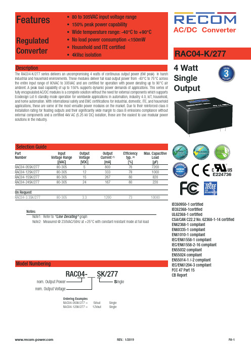
Recom RAC AC DC Converter 产品说明说明书

RAC AC/DC ConverterFeaturesRegulated Converter• Wide input range 85-305VAC• Standby mode optimized (eco design Lot 6)• High efficiency over the entire load range • Operating temperature range: -40°C to +90°C • Overvoltage and overcurrent protected• EMC compliant without external components • Encapsulated module with pins or wiredDescriptionThe RAC05-K/277 series are multipurpose 5 watt AC/DC power supplies for enhanced mains input conditions from 90VAC up to 305VAC with an extra wide operating temperature range from -40°C to +90°C. These modules are designed to supply worldwide applications in automation, Industry 4.0, IoT, household and smart buildings. For worldwide use they come with international safety certifications for industrial, domestic and ITE as well as household standards. With both PCB-mount and wired packages, fully protected outputs, and EMC class B emissions compliance without any external components, these are the easiest to use modular power solutions in the industry.E224736RAC05-__ SK/277/WModel NumberingOrdering Examples:RAC05-05SK/277 5 Watt 5Vout Single Output THT version RAC05-24SK/277 5 Watt 24Vout Single Output THT version RAC05-05SK/277/W 5 Watt 5Vout Single Output Wired version RAC05-12SK/277/W5 Watt 12Vout Single Output Wired versionS inglenom. Output PowerOutput Voltage5 Watt Single OutputRAC05-K/277Selection GuidePart Input Output Output Efficiency Max. CapacitiveNumber Voltage Range Voltage Current typ (1) Load (2)[VAC] [VDC] [mA] [%] [µF]RAC05-3.3SK/277 85-305 3.3 1510 77 10000RAC05-05SK/277 85-305 5 1000 80 8000RAC05-12SK/277 85-305 12 416 83 1500RAC05-15SK/277 85-305 15 330 83 1000RAC05-24SK/277 85-305 24 210 84 330Notes:Note1: Efficiency is tested at nominal input and full load at +25°C ambient Note2: Max Cap Load is tested at nominal input and full resistive loadW ired Notes:Note3: add suffix …W“ for wired versionwithout suffix, standard THT versionUL62368-1 certified EN62368-1 certified IEC/EN60335-1 certified EN62233 certifiedIEC/EN61558-1 certified IEC/EN61558-2-16 certified EN55032 compliantEN55014-1(-2) compliant CB ReportSpecifications(measured @ Ta= 25°C, nom. Vin, full load and after warm-up unless otherwise stated)Specifications (measured @ Ta= 25°C, nom. Vin, full load and after warm-up unless otherwise stated)REGULATIONSParameterConditionValueOutput Accuracy ±1.0% typ.Line Regulation low line to high line, full load±0.5% typ. Load Regulation (7)10% to 100% load 1.0% typ.Transient Response25% load step change4.0% max.recovery time500µs typ.PROTECTIONSParameterTypeValueInput Fuse (8)internal T1A, slow blowShort Circuit Protection (SCP)below 100m Whiccup, automatic restart Over Voltage Protection (OVP)125% - 195%, latch of modeOver Voltage Category OVC IIOver Current Protection (OCP)125% - 195%, hiccup modeClass of EquipmentClass IIIsolation Voltage (safety certified) (9)I/P to O/P1 minute4.2kVACIsolation Resistance Isolation Voltage 500VDC 1G W min.Isolation Capacitance 100pF max.Insulation Grade reinforced Leakage Current0.25mA max.continued on next pageDeviation vs. Load(at 115VAC, 230VAC, 277VAC)10.50-0.5-1D e v i a t i o n [%]102030405060708090100Output Load [%]10.5-0.5-1D e v i a t i o n [%]0102030405060708090100Output Load [%]RAC05-05SK/277RAC05-12SK/277Notes:Note8: Refer to local safety regulations if input over-current protection is also required Note9: For repeat Hi-Pot testing, reduce the time and/or the test voltageNotes:Note7: Operation below 10% load will not harm the converter, but specifications may not be metSpecifications(measured @ Ta= 25°C, nom. Vin, full load and after warm-up unless otherwise stated)Specifications(measured @ Ta= 25°C, nom. Vin, full load and after warm-up unless otherwise stated)SAFETY AND CERTIFICATIONSCertificate Type (Safety)Report / File Number StandardAudio/Video, information and communication technology equipment - Part 1: Safety requirements E491408-A6004-ULUL62368-1, 2nd Edition, 2014-12-01CAN/CSA-C22.2 No. 62368-1-14, 2nd Edt., 2014-12Audio/Video, information and communication technology equipment -Part 1: Safety requirements (CB Scheme)E491408-A6007-CB-1IEC62368-1:2014 2nd EditionAudio/Video, information and communication technology equipment -Part 1: Safety requirements (LVD)EN62368-1:2014 + A11:2017Household and similar electrical appliances - Safety -Part 1: General requirementsLCS190308001CS IEC60335-1:2010 + A2:2016 + C1:2016, 5th Edt.EN60335-1:2012 + A13:2017Measurement methods for electromagnetic fields of household appliances and similarapparatus with regard to human exposureEN62233:2008Safety of power transformers, power supplies, reactors and similar products for sup-ply voltages up to 1100 V (CB Scheme)50230493 001IEC61558-1:2005 2nd Edition + A1:2009Safety of power transformers, power supplies, reactors and similar products for sup-ply voltages up to 1100 V Part 2: Particular requirements (CB Scheme)IEC61558-2-16:2009 1st Edition + A1:2013 Safety of power transformers, power supplies, reactors and similar products for sup-ply voltages up to 1100 VEN61558-1:2005 + A1:2009 Safety of power transformers, power supplies, reactors and similar products for sup-ply voltages up to 1100 V Part 2: Particular requirementsEN61558-2-16:2009 + A1:2013 RoHS2RoHS-2011/65/EU + AM-2015/863 EMC Compliance Conditions Standard / Criterion Low-voltage power supplies DC output - Part 3: Electromagnetic compatibility EN61204-3: 2018, Class B Electromagnetic compatibility of multimedia equipment - Emission requirements (11)EN55032:2015, Class B Electromagnetic compatibility - Requirements for household appliances, electric toolsand similar apparatus - Part 1: EmissionEN55014-1:2006 + A2:2011 I nformation technology equipment - Immunity characteristics - Limits and methods of measurement EN55024:2010 + A1:2015 Electromagnetic compatibility - Requirements for household appliances, electric toolsand similar apparatus - Part 2: ImmunityEN55014-2:2015ESD Electrostatic discharge immunity testAir: ±2, 4, 8kVContact: ±2, 4kVEN61000-4-2: 2009, Criteria BRadiated, radio-frequency, electromagnetic field immunity test 10V/m, 80MHz-1GHz3V/m, 1.4GHz-2GHz1V/m, 2GHz-2.7GHzEN61000-4-3: 2006 + A1, 2009, Criteria AFast Transient and Burst Immunity AC and DC Port: ±2kV EN61000-4-4: 2012, Criteria BSurge Immunity AC In Port (L-N): ±1kVDC Output Port: ±0.5kVEN61000-4-5: 2014 +A1:2017, Criteria BImmunity to conducted disturbances, induced by radio-frequency fields AC and DC Port: 10V EN61000-4-6: 2014, Criteria A Power Magnetic Field Immunity50Hz, 30A/m EN61000-4-8: 2010, Criteria AVoltage Dips and InterruptionsVoltage Dips: 30%Voltage Dips: 60%Voltage Dips: 100%Interruptions: >95%EN61000-4-11:2004 + A1:2017, Criteria CEN61000-4-11:2004 + A1:2017, Criteria CEN61000-4-11:2014 + A1:2017, Criteria BEN61000-4-11: 2014 + A1:2017,Criteria CVoltage Fluctuations and Flicker in Public Low-Voltage Systems <=16A per phase EN61000-3-3: 2013 Limitations on the amount of electromagnetic interference allowed from digital and electronic devices FCC 47 CFR Part 15 Supbart B, Class B Methods of Measurement of Radio-Noise Emissions from Low-Voltage Electrical andElectronic Equipment in the Range of 9 kHz to 40 GHzANSI C63.4-2014, Class BNotes:Note11: If output is connected to GND, please contact RECOM tech support for adviceSpecifications(measured @ Ta= 25°C, nom. Vin, full load and after warm-up unless otherwise stated)Specifications (measured @ Ta= 25°C, nom. Vin, full load and after warm-up unless otherwise stated)The product information and specifications may be subject to changes even without prior written notice.The product has been designed for various applications; its suitability lies in the responsibility of each customer. The products are not authorized for use in safety-critical applications without RECOM’s explicit written consent. A safety-critical application is an application where a failure may reasonably be expected to endanger or cause loss of life, inflict bodily harm or damage property. The applicant shall indemnify and hold harmless RECOM, its affiliated companies and its representatives against any damage claims in connection with the unauthorizeduse of RECOM products in such safety-critical applications.PACKAGING INFORMATIONParameterTypeValuePackaging Dimension (LxWxH)THT wiredtube tray466.0 x 30.4 x 29.3mm 468.0 x 198.0 x 46.0mmPackaging Quantity THT wired12pcs 24pcsStorage Temperature Range -40°C to +85°C Storage Humiditynon-condensing 20% to 90% RH max.。
DM9000中文手册

,011)被选 中
访问类型 高电平
是访问数据 端口;低电平 是访问地址 端口
字命令标志, 默认低电平 有效
当访问 外部数据存 储器是字或 双字宽度时, 被置位
100
INT
O
中断请求信 号
高电平 有效,极性能 修改
37~53 56
SD31~16
I/O
双字模式,高 16 位数据引 脚
注意:以上介质无关端口都内部自带 60K 欧姆的下拉电阻 处理器接口引脚
1
IOR#
I
2
IOW#
I
3
AEN#
I
处理器读命 令
低电平 有效,极性能 够被 EEPRO M 修改,详细 请参考对 EE PROM 内容 的描述
处理器写命 令
低电平 有效,同样能 修改极性
芯片选择,低
4
IOWAIT
O
14
RST
外部介质无 关接口发送 时钟
外部介质无 关接口发送 数据低 4 位
输出
TXD[2: 0]决定内部 存储空间基 址:TXD [2: 0]) * 10H +
300H
54
MDIO
I/O
外部介质无
关接口串行
数据通信
57
MDC
O
外部介质无 关串行数据 通信口时钟, 且与中断引 脚有关
该引脚 高电平时候, 中断引脚低 电平有效;否 则高有效
0 0 16 位
0 1 32 位
108 位
11未 定义
66
EECK
I
时钟信号
67
EECS
I/O
片选
也做 LE D 模式选择 引脚
伟创AC90变频器说明书7外围设备及选购件

7 外围设备及选购件7.1安全注意事项用户在使用外围设备及选购件时,须遵从以下安全注意事项及相关要求。
● 请勿在电源接通的状态下进行相关作业,否则会有触电的危险。
● 进行相关作业前,请切断所有设备的电源,并确认主回路直流电压已经下降到安全水平,等5分钟后再进行相关作业。
● 请勿在拆下变频器外罩/面板的状态下运行,否则会有触电的危险。
● 请勿在通电状态时拆下变频器的外罩或触摸印刷电路板,否则会有触电的危险。
● 本产品、外围设备及选购件必须由专业人员进行安装、调试、维保,否则可能导致危险。
● 进行安装、调试、维保等工作时,请不要穿宽松的衣服,并采用相关保护工具和保护措施。
● 在变频器运行中,请勿更改接线、拆下跳线、选购卡、或更换冷却风扇,否则会有触电的危险。
● 请按指定的力矩来紧固端子螺丝。
主回路电线的连接处如果松动,可能会因电线连接处的过热而引发火灾。
● 本产品、外围设备及选购件必须可靠接地,防止由于漏电、感应电势对人体的伤害。
● 进行相关作业前,请遵守静电防止措施(ESD)规定的措施和方法,否则可能损坏变频器。
● 在变频器输出电压的过程中,请勿切断供电电源,否则会导致变频器损坏。
7.2外围设备 常用外围设备如下表所示。
关于外围设备的订购,请咨询本公司代理商或销售部门。
外围设备名称 使用目的断路器发生短路事故时保护电源系统、防止故障扩大影响其它正常设备工作,并起到过载保护的作用。
漏电断路器 防止触电事故的接地保护(建议使用防止高频漏电流型)。
电磁接触器 切实分开电源与变频器,并实现基本继电控制。
交流输入电抗器提高电源侧功率因数,隔离电源侧噪声信号对变频器的干扰。
直流电抗器 抑制高次谐波,改善电源功率因数。
输入侧噪音滤波器降低变频器对电源的干扰,同时有效降低来自电网的干扰。
制动电阻器 电气制动的被动能量消耗单元。
能耗制动单元电气制动控制单元,用于控制制动电阻器有效消耗电机的再生电能。
输出侧噪音滤波器 降低变频器输出侧电线的电磁干扰。
nt90rnae24cb工作原理(一)
nt90rnae24cb工作原理(一)NT90RNAE24CB工作原理1. 什么是NT90RNAE24CBNT90RNAE24CB是一款高性能、智能的电子产品,能够广泛应用于各个领域。
它基于先进的技术和专业的设计,能够提供稳定、高效的工作性能。
2. 工作原理概述NT90RNAE24CB的工作原理可以简单概括为以下几个方面:•电子信号处理:NT90RNAE24CB接收输入的电子信号,并通过先进的处理技术对其进行分析和处理。
•数据存储与处理:NT90RNAE24CB内部设有存储和处理器单元,用于存储和处理电子信号的数据。
•电能转换:NT90RNAE24CB能够将外部电源供应的电能转换为内部电路和组件所需的工作电能。
•控制逻辑:通过内置的控制逻辑,NT90RNAE24CB能够对输入信号和输出信号进行控制和调节。
•交互界面:NT90RNAE24CB通常还具备交互界面,例如按钮、显示器等,用于用户和设备之间的交互操作。
3. 电子信号处理NT90RNAE24CB通过接收输入的电子信号进行工作。
这些电子信号可以是来自各种传感器、设备或其他电子产品的信号。
在信号输入后,NT90RNAE24CB会进行滤波、放大、滤波等处理,以确保输入信号的稳定性和准确性。
4. 数据存储与处理NT90RNAE24CB内部设有存储和处理器单元,用于存储和处理电子信号的数据。
这些数据可以是输入信号的原始数据、处理后的数据、或者是设备的状态信息等。
NT90RNAE24CB可以对这些数据进行计算、转换和存储,以便后续的操作和应用。
5. 电能转换NT90RNAE24CB需要工作电源来提供工作所需的电能。
通常情况下,NT90RNAE24CB能够接受不同电压和频率的电源供应。
内部的电能转换器可以将外部的电源电能转换为设备内部电路和组件所需的适当电能。
6. 控制逻辑NT90RNAE24CB内置了控制逻辑,可以对输入信号和输出信号进行控制和调节。
控制逻辑可以根据设备运行状态、输入信号变化等来进行决策和控制。
伟创AC90变频器说明书6定期检查与维护
6 定期检查与维护6.1安全注意事项本节对检查、维护本产品时所必须遵照的各种注意事项进行的说明。
● 请勿在电源接通的状态下进行相关作业,否则有触电致人死亡的危险。
● 进行相关作业前,请切断所有关联设备的电源,并确认主回路直流电压已经下降到安全水平,等5分钟后再进行相关作业。
● 请勿在拆下变频器外罩/面板的状态下运行,否则会有触电的危险。
● 请勿在通电状态时拆下变频器的外罩或触摸印刷电路板,否则会有触电的危险。
● 本产品的维护保养、更换配件必须由专业人员进行,否则可能导致危险。
● 进行安装、调试、维保等工作时,请不要穿宽松的衣服,并采用相关保护工具和保护措施。
● 请按指定的力矩来紧固端子螺丝。
主回路电线的连接处如果松动,可能会因电线连接处的过热而引发火灾。
● 请务必将机器、电机可靠接地。
否则会因与电机机壳的接触而导致触电。
● 进行相关作业前,请遵守静电防止措施(ESD)规定的措施和方法,否则可能损坏变频器。
● 请勿更改变频器的回路和结构,否则会导致变频器损坏。
● 请在电机空载下确认转向,错误的旋转方向可能造成人身伤害或重大财产损失。
● 请不要使用已经损坏的机器,否则可能导致事故或发生危险。
6.2检查变频器由半导体器件、无源电子器件、以及运动器件构成,而这些器件都有使用寿命,即使在正常的工作环境下,如果超过使用年限,部分器件可能产生特性变化或失效。
为了防止该现象导致故障,必须进行日常检查、定期检查、器件更换等预防性检查维护。
建议在机器安装后每 3~4个月进行一次检查。
如有下述情况,请缩短检查周期。
高温、高海拔环境; 频繁起动、停止的环境;存在交流电源或负载有较大波动的环境; 存在过大振动或冲击的环境;存在灰尘、金属粉尘、盐类、硫酸、氯元素的环境; 恶劣的保存环境。
● 日常检查为了避免变频器损坏及使用寿命缩短,请每日对以下项目进行确认。
检查项目 检查内容应对策略供电电源 检查供电电压是否符合要求及有无缺相供电现象。
PHOENIX CONTACT UNO POWER 24V DC 90W 电源设备说明书
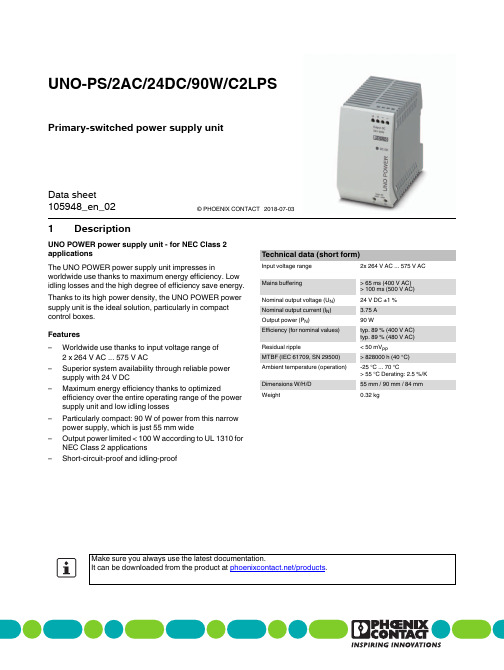
1DescriptionPrimary-switched power supply unitUNO-PS/2AC/24DC/90W/C2LPS© PHOENIX CONTACT Data sheetUNO POWER power supply unit - for NEC Class 2applicationsThe UNO POWER power supply unit impresses in worldwide use thanks to maximum energy efficiency. Low idling losses and the high degree of efficiency save energy. Thanks to its high power density, the UNO POWER power supply unit is the ideal solution, particularly in compact control boxes.Features–Worldwide use thanks to input voltage range of2 x 264 V AC ... 575 V AC–Superior system availability through reliable power supply with 24 V DC–Maximum energy efficiency thanks to optimized efficiency over the entire operating range of the power supply unit and low idling losses–Particularly compact: 90 W of power from this narrow power supply, which is just 55 mm wide–Output power limited < 100 W according to UL 1310 for NEC Class 2 applications–Short-circuit-proof and idling-proof Technical data (short form)Input voltage range2x 264 V AC ... 575 V AC Mains buffering> 65 ms (400 V AC)> 100 ms (500 V AC) Nominal output voltage (U N)24 V DC ±1 %Nominal output current (I N) 3.75 AOutput power (P N)90 WEfficiency (for nominal values)typ. 89 % (400 V AC)typ. 89 % (480 V AC) Residual ripple< 50 mV PPMTBF (IEC 61709, SN 29500)> 828000 h (40 °C) Ambient temperature (operation)-25 °C ... 70 °C> 55 °C Derating: 2.5 %/K Dimensions W/H/D55 mm / 90 mm / 84 mm Weight0.32 kgMake sure you always use the latest documentation.It can be downloaded from the product at /products. 105948_en_022018-07-032Table of contents1Description (1)2Table of contents (2)3Ordering data (3)4Technical data (4)5Intended use (9)6Structure (9)6.1 Device elements (9)6.2 Block diagram (9)7Mounting (10)7.1 Unpacking (10)7.2 Mounting the power supply unit (10)7.3 Mounting on a DIN rail (12)7.4 Normal mounting position (12)8Installing the power supply unit (13)8.1 Safety regulations and installation notes (13)8.2 High-voltage test (HIPOT) (14)8.3 Mains connection (15)8.4 Device connections (16)8.5 Connecting cables (16)9Operating behavior of the power supply unit (17)9.1 Normal operation (17)9.2 Overload response (17)9.3 Behavior at ambient temperatures > 55°C (17)9.4 Behavior in the case of alternative mounting positions (18)10Operating the power supply unit (21)10.1 Function monitoring (21)10.2 Operating power supply units in parallel or in series (22)11Removal (22)11.1 Removing the power supply unit (22)11.2 Notes on disposal (22)Description T ype Order No.Pcs./Pkt.Primary-switched UNO POWER power supply for DIN rail mounting, input: 2-phase, output: 24 V DC/90 W UNO-PS/2AC/24DC/90W/C2LPS290437113Ordering dataAccessories T ype Order No.Pcs./Pkt. Multi-channel electronic device circuit breaker forprotecting four loads at 24 V DC in the event of overloadand short circuit. With electronic locking of the set nominalcurrents. For installation on DIN rails.CBMC E4 24DC/1-4A NO29060311Multi-channel electronic device circuit breaker forprotecting four loads at 24 V DC in the event of overloadand short circuit. With electronic locking of the set nominalcurrents. For installation on DIN rails.CBMC E4 24DC/1-10A NO29060321Type 3 surge protection, consisting of protective plug andbase element, with integrated status indicator and remotesignaling for single-phase power supply networks.Nominal voltage 24 V AC/DC.PLT-SEC-T3-24-FM-UT29079165 Our range of accessories is being continually extended, our current range can be found in the download area.4Technical dataInput dataNominal input voltage2x 400 V AC ... 500 V ACInput voltage range2x 264 V AC ... 575 V ACFrequency range (f N)50 Hz ... 60 Hz ±5 HzCurrent consumption (for nominal values) typ.0.55 A (400 V AC)0.48 A (500 V AC)Inrush current limitation (at 25°C) typ.< 30 AI2t typ.< 0.5 A2sMains buffering> 65 ms (400 V AC)> 100 ms (500 V AC)Protective circuit Transient surge protection VaristorInput fuse, integrated 2 A (slow-blow, internal)6 A ... 16 AChoice of suitable circuit breakersCharacteristics B, C, D, KInput connection dataConnection method Screw connectionConductor cross section, solid0.2 mm² ... 2.5 mm²Conductor cross section, flexible0.2 mm² ... 2.5 mm²Conductor cross section AWG/kcmil24 (14)Stripping length8 mmScrew thread M3Tightening torque0.5 Nm ... 0.6 NmOutput dataNominal output voltage (U N)24V DC±1 %Nominal output current (I N) 3.75 A3.38 A (Derating 10 %)Derating55 °C ... 70 °C (2.5%/K)Control deviation< 1 % (change in load, static 10 % ... 90 %)< 3 % (Dynamic load change 10 % ... 90 %, 10 Hz)< 0.1 % (change in input voltage ±10 %)Rise time< 0.5 s (U OUT (10 % ... 90 %))Residual ripple< 50 mV PP (with nominal values)Connection in parallel NoConnection in series NoProtection against surge voltage on the output≤ 35 V DCFeedback resistance< 35 V DCOutput connection dataConnection method Screw connectionConductor cross section, solid0.2 mm² ... 2.5 mm²Conductor cross section, flexible0.2 mm² ... 2.5 mm²Conductor cross section AWG/kcmil24 (14)Stripping length8 mmScrew thread M3Tightening torque0.5 Nm ... 0.6 NmPower consumptionEfficiency (for nominal values) typ.89 % ( 400 V AC ) / 89 % ( 480 V AC )Maximum power dissipation in no-load condition< 0.7 WPower loss nominal load max.< 12 WGeneral dataInsulation voltage input/output 4 kV AC (type test)3 kV AC (routine test)MTBF (IEC 61709, SN 29500)> 828000 h (40 °C)Housing material PolycarbonateFoot latch material POM (Polyoxymethylen)Inflammability class in acc. with UL 94 (housing / terminalV0blocks)Degree of protection IP20Protection class II ( in closed control cabinet )Dimensions W/H/D55 mm / 90 mm / 84 mmWeight0.32 kgAmbient conditionsAmbient temperature (operation)-25 °C ... 70 °C (> 55 °C Derating: 2.5 %/K)Ambient temperature (storage/transport)-40 °C ... 85 °CMax. permissible relative humidity (operation)≤ 95 % (at 25 °C, non-condensing)Vibration (operation)< 15 Hz, amplitude ±2.5 mm (according to IEC 60068-2-6)15 Hz ... 150 Hz, 2.3g, 90 min.Shock18 ms, 30g, in each space direction (according to IEC 60068-2-27)Degree of pollution2Climatic class3K3 (in acc. with EN 60721)StandardsEN 61558-2-16Safety of power supply units up to 1100 V (insulationdistances)IEC 60950-1/VDE 0805 (SELV)Electrical safety (of information technology equipment -Safety - Part 1)Electronic equipment for use in electrical powerEN 50178/VDE 0160 (PELV)installationsSELV IEC 60950-1 (SELV) and EN 60204-1 (PELV)Safe isolation DIN VDE 0100-410Limitation of mains harmonic currents EN 61000-3-2Network version/undervoltage EN 61000-4-11Information technology equipment - Safety (CB Scheme)CB SchemeApprovalsUL approvals UL/C-UL listed UL 508UL/C-UL Recognized UL 60950-1NEC Class 2 as per UL 1310UL/C-UL Listed ANSI/ISA-12.12.01 Class I, Division 2, GroupsA, B, C, D T4 (Hazardous Location)CSA CAN/CSA-C22.2 No. 60950-1-07CSA-C22.2 No. 107.1-01CAN/CSA-C22.2 No. 213 Class I, Division 2, Groups A, B, C, DT4 (Hazardous Location)Current approvals/permissions for the product can be found in the download area under/productsConformance with EMC Directive 2014/30/EUNoise immunity according to EN 61000-6-2EN 61000-6-2 requirement tested Electrostatic discharge EN 61000-4-2Housing contact discharge 4 kV (Test Level 2) 6 kV (Test Level 3)Housing air discharge8 kV (Test Level 3)8 kV (Test Level 3)Comments Criterion B Criterion B Electromagnetic HF field EN 61000-4-3Frequency range80 MHz ... 1 GHz80 MHz ... 1 GHzTest field strength10 V/m10 V/mFrequency range 1.4 GHz ... 2 GHz 1 GHz ... 2 GHzTest field strength 3 V/m10 V/mFrequency range 2 GHz ... 2.7 GHz 2 GHz ... 3 GHzTest field strength 1 V/m10 V/mComments Criterion A Criterion AFast transients (burst) EN 61000-4-4Input 2 kV (Test Level 3 - asymmetrical)4 kV (Test Level 4 - asymmetrical)Output 2 kV (Test Level 3 -asymmetrical)2 kV (Test Level 3 - asymmetrical)Comments Criterion B Criterion B Surge current loads (surge) EN 61000-4-5Input 1 kV (Test Level 2 - symmetrical)2 kV (Test Level3 -asymmetrical)2 kV (Test Level 3 - symmetrical)4 kV (Test Level 4 - asymmetrical)Output0.5 kV (Test Level 1 -symmetrical)0.5 kV (Test Level 1 -asymmetrical)1 kV (Test Level 2 - symmetrical)2 kV (Test Level3 - asymmetrical)Comments Criterion B Criterion BConducted interference EN 61000-4-6Frequency range10 kHz ... 80 MHz10 kHz ... 80 MHzVoltage10 V (Test Level 3)10 V (Test Level 3)Comments Criterion A Criterion AKeyCriterion A Normal operating behavior within the specified limits. Criterion B Temporary impairment to operational behavior that is correctedby the device itself.Emitted interference in acc. with EN 61000-6-3Radio interference voltage in acc. with EN 55011EN 55011 (EN 55022) Class B, area of application: Industryand residentialEmitted radio interference in acc. with EN 55011EN 55011 (EN 55022) Class B, area of application: Industryand residentialAll technical specifications are nominal values and refer to a room temperature of 25 °C and 70 % relativehumidity at 100 m above sea level.5Intended useThis power supply unit features IP20 protection and is intended for installation in housing. It is suitable for use in industrial applications.6Structure6.1Device elementsFigure 1Device elements1.Connection terminal block input voltage:Input AC L1/L, L2/N2.Connection terminal block output voltage:Output DC +/-3.LED signaling DC OK (green)4.Integrated snap-on foot for carrier rail mounting6.2Block diagramFigure 2Block diagram7Mounting7.1UnpackingBefore mounting the power supply unit, it must be checked for damage:–Take the device out of its packaging.–Check the device for any damage sustained during transport.–Retain the package slip for future use.–Dispose of packaging in an environmentally-friendly way.7.2Mounting the power supply unitThe power supply unit is intended forinstallation in a distributor box or controlcabinet.The power supply unit is designed forconvection cooling. Maintain a minimumdistance from other devices in order to ensureconvection cooling.Figure3ConvectionPlease note the following before mounting the power supply unit:–The minimum distance from other devices that must be observed in order to ensure convection cooling is: 30mm vertically, 0 mm horizontallyFigure5Device dimensions7.3Mounting on a DIN railThe power supply unit can be installed on all 35 mm DIN rails according to EN 60715.Figure6Mounting on a DIN rail7.4Normal mounting positionWhen installed, the input terminal blocks must be at the bottom and the output terminal blocks at the top.If the power supply unit is installed in a mounting position other than the normal mounting position, the output power must be reduced.Figure7Normal mounting position8Installing the power supply unit8.1Safety regulations and installation notes–It is not permissible to open or modify thedevice. Do not repair the device yourselfbut replace it with an equivalent device.Repairs may only be carried out by themanufacturer. The manufacturer is notliable for damage resulting from violation.–The device may only be used for itsintended use.8.2High-voltage test (HIPOT)This protection class II power supply is subject to the Low Voltage Directive and is factory tested. During the HIPOT test (high-voltage test), the insulation between the input circuit and output circuit is tested for the prescribed electric strength values, for example. The test voltage in the high-voltage range is applied at the input and output terminal blocks of the power supply. The operating voltage used in normal operation is a lot lower than the test voltage used. 8.2.1High-voltage dielectric test (dielectric strengthtest)In order to protect the user, power supplies (as electric components with a direct connection to potentially hazardous voltages) are subject to more stringent safety requirements. For this reason, permanent safe electrical isolation between the hazardous input voltage and the touch-proof output voltage as safety extra-low voltage (SELV) must always be ensured.In order to ensure permanent safe isolation of the AC input circuit and DC output circuit, high-voltage testing is performed as part of the safety approval process (type test) and manufacturing (routine test).8.2.2High-voltage dielectric test during themanufacturing processDuring the manufacturing process for the power supply, a high-voltage test is performed as part of the dielectric test in accordance with the specifications of IEC/UL/EN 60950-1. The high-voltage test is performed with a test voltage of at least 3 kV AC / 4.3 kV DC or higher. Routine manufacturing tests are inspected regularly by a certification body.8.2.3High-voltage dielectric test performed by thecustomerApart from routine and type tests to guarantee electrical safety, the end user does not have to perform another high-voltage test on the power supply as an individual component. According to EN 60204-1 (Safety of machinery - Electrical equipment of machines) the power supply can be disconnected during the high-voltage test and only installed once the high-voltage test has been completed.8.2.4Performing high-voltage testingIf high-voltage testing of the control cabinet or the power supply as a stand-alone component is planned during final inspection and testing, the following features must be observed.–The power supply wiring must be implemented as shown in the wiring diagram.–The maximum permissible test voltages must not be exceeded.Avoid unnecessary loading or damage to the power supply due to excessive test voltages.Figure8Potential-related wiring for the high-voltagetestKeyThe test voltage should rise and fall in rampform. The relevant rise and fall time of theramp should be at least two seconds.For the relevant applicable test voltages andinsulation distances, refer to thecorresponding table (see technical data).No.Designation Color coding Potentiallevels1DC output circuit Blue Potential 22High-voltagetester----3AC input circuit Red Potential 18.3Mains connectionThe device can be connected to single-phase AC or three-phase power grids (TN-S, TN-C, TT, and IT) while considering the nominal input voltage.Figure9Network types8.4Device connectionsScrew connection for input AC L1/L, L2/NFigure10Screw connection for input AC L1/L, L2/N Screw connection for output DC +/-Figure11Screw connection for output DC +/-8.5Connecting cablesFigure12Connecting cables1.Connect the supply lines to the input AC L1/L, L2/Nconnection terminal blocks.2.Connect the output cables to the output DC +/-connection terminal blocks.The power supply unit is operational as soon as the input terminal blocks are supplied with voltage.9Operating behavior of the power supply unit9.1Normal operationIn normal operation, the loads are supplied with a constant output voltage of 24 V DC.9.2Overload responseIn the event of overload (I > I N), the device reduces its output voltage. If the output voltage is greater than U N x 0.9, the green DC OK LED lights up. If the output voltage drops below U N x 0.5, the device shuts down. After a short time, the device attempts to start up again. If the overload has been rectified, it will start up as normal. If the overload has still not been rectified, it will shut down again and attempt to restart again (automatic restart).Figure13Output characteristic curve9.3Behavior at ambient temperatures > 55°CAt an ambient temperature of up to 55 °C, the power supply unit supplies the nominal output current. At ambient temperatures upwards of 55 °C, the output power must be reduced by 2.5 % per Kelvin temperature increase (temperature-dependent derating).Figure14Temperature-dependent derating9.4Behavior in the case of alternative mountingpositionsFor mounting positions that differ from the normal mounting position, the output power must be reduced (position-dependent derating).The characteristic curve can be used to determine the maximum output power to be drawn for each ambient temperature for different mounting positions.Normal mounting positionRotated mounting position 90° X-axisRotated mounting position 180° X-axisRotated mounting position 270° X-axisRotated mounting position 90° Z-axisRotated mounting position 270° Z-axis10Operating the power supply unit10.1Function monitoringDC OK LEDThe DC OK LED is available for visual function monitoring ofthe power supply unit.Status 1Status 2DC OK LED lit offMeaning Output voltage > 21.5 V Output voltage < 21.5 V DC, overloadmode or no mains voltageState description The device is operating, output voltageand output current are OK The device is in operation, but there is a fault on the side of the consumer; the current consumption is greater than IN or the output is short-circuited.The device is out of operation because there is no mains voltage, the fuse on the primary side has been triggered, or the device is faulty.Corrective Remove the error at the load, use amore powerful power supply unit,connect a power supply unit of the sametype parallel to the existing device,remove the short circuit, apply mainsvoltage, enable the fuse again orreplace the power supply unit.105948_en_02PHOENIX CONTACT21 / 22105948_en_0222 / 22PHOENIX CONTACT GmbH & Co. KG • 32823 Blomberg • Germany10.2Operating power supply units in parallel or in seriesDo not connect two power supply units of this type in parallel or in series, because they then no longer fulfil therequirement of the NEC Class 2 American safety regulation (output power of the power supply unit < 100 W).11Removal11.1Removing the power supply unitFigure 15Removal11.2Notes on disposal。
RECOM 电源 RACAC DC 转换器 PA-1 产品说明书
RAC AC/DC Conver er4 Watt Single OutputRAC04-K/277IEC60950-1 certified IEC62368-1certified UL62368-1 certifiedCSA/CAN C22.2 No. 62368-1-14 certified EN62368-1 compliant EN60335-1 compliant EN61010-1 compliant IEC/EN61558-1 compliant IEC/EN61558-2-16 compliant EN55032 compliant EN55024 compliantEN55014-1 /-2 compliant IEC/EN61204-3 compliant FCC 47 Part 15CB ReportSelection GuidePart Input Output Output Efficiency Max. CapacitiveNumber Voltage Range Voltage Current (1) typ. (2)Load [(VAC] [VDC] [mA] [%] [µF)RAC04-05SK/277 80-305 5 800 76 7200RAC04-12SK/277 80-305 12 333 78 1000RAC04-15SK/277 80-305 15 267 80 820RAC04-24SK/277 80-305 24 167 80 220On RequestRAC04-3.3SK/277 80-305 3.3 1200 73 10000Notes:Note1: Refer to “Line Derating“ graphNote2: Measured @ 230VAC/50Hz at +25°C with constant resistant mode at full loadDescriptionThe RAC04-K/277 series delivers an uncompromising 4 watts of continuous output power (6W peak) in harsh industrial and household environments. These modules deliver full load output power from -40°C to 75°C across the entire input range of 80VAC to 305VAC and are certified for operation with power derating up to 90°C air ambient. A peak load capability of up to 150% supports dynamic power demands of applications. This series of fully encapsulated AC/DC modules is a complete solution without the need for external components which supports Ecodesign Lot 6 standby mode operation for worldwide applications in automation, industry 4.0, IoT, household, and home automation. With international safety and EMC certifications for industrial, domestic, ITE, and household applications, these are some of the most versatile power modules on the market. Due to their reinforced class II installation rating for floating outputs and their significantly wide margin to class B emissions compliance without external components and a certified 4kV AC (5.25 kV DC) isolation, these are the easiest to use modular power solutions in the industry.nom. Output Power nom. Output VoltageRAC04-__ SK/277Model NumberingS ingleE224736Ordering Examples RAC04-05SK/277 = 5Vout Single RAC04-12SK/277 =12VoutSingleSpecifications (measured @ Ta= 25°C, nom. Vin, full load and after warm-up unless otherwise stated)Specifications (measured @ Ta= 25°C, nom. Vin, full load and after warm-up unless otherwise stated)REGULATIONSParameterCondition ValueOutput Accuracy ±1.0% typ.Line Regulation ±0.5% typ.Load Regulation 1.0% typ.Transient Response25% load step changerecovery time4.0% max.500µs10.5-0.5-1D e v i a t i o n [%]0102030405060708090100Output Load [%]10.50-0.5-1D e v i a t i o n [%]0102030405060708090100Output Load [%]RAC04-05SK/277RAC04-12SK/277Deviation vs. Load(80-305VAC)Specifications (measured @ Ta= 25°C, nom. Vin, full load and after warm-up unless otherwise stated)10.5-0.5-1D e v i a t i o n [%]0102030405060708090100Output Load [%]10.50-0.5-1D e v i a t i o n [%]0102030405060708090100Output Load [%]RAC04-15SK/277RAC04-24SK/277Specifications (measured @ Ta= 25°C, nom. Vin, full load and after warm-up unless otherwise stated)SAFETY AND CERTIFICATIONSCertificate Type Report / File Number StandardAudio/video, information and communication technology equipment - Safety requirements E224736UL62368-1:2014, 2nd Edition CAN/CSA C22.2 No. 62368-1-14, 2nd EditionInformation Technology Equipment, General Requirements for Safety (CB)E491408-A6-CB-1IEC60950-1:2005 + A2:2013, 2nd EditionInformation Technology Equipment, General Requirements for Safety EN60950-1:2006 + A2:2013 Audio/video, information and communication technology equipment - Safety requirements (CB)E491408-A6011-CB-1IEC62368-1:2014, 2nd Edition Audio/video, information and communication technology equipment - Safety requirements (LVD)EN62368-1:2014 + A11:2017 Household and similar electrical appliances - Safety - Part 1: General requirements (LVD)EN60335-1:2012 + A1:2018Safety of power transformers, power supplies, reactors and similar products for supply voltages up to 1100 V IEC61558-1:2005 2nd Edition + A1:2009EN61558-1:2005 + A1:2009Specifications (measured @ Ta= 25°C, nom. Vin, full load and after warm-up unless otherwise stated)Certificate Type Report / File Number StandardSafety of transformers, reactors, power supply units and similar products for supply voltages up to 1100 V - Part 2-16: Particular requirements and tests for switch mode power supply units and transformers for switch mode power supply units (LVD)IEC61558-2-16:2009 + A1:2013, 1st EditionEN61558-2-16:2009 + A1:2013Safety requirements for electrical equipment for measurement, control and laboratory use -Part 1: General requirements (LVD)EN61010-1:2010 RoHS2RoHs-2011/65/EU + AM-2015/863 EMC Compliance (Household)Report / File Number Standard / Criterion Electromagnetic compatibility - Requirements for household appliances, electric tools and similarapparatus - Part 1: Emission (8)EN55014-1:2006 + A2:2011 Electromagnetic compatibility - Requirements for household appliances, electric tools and similarapparatus - Part 2: ImmunityEN55014-2:2015 ESD Electrostatic discharge immunity test Air ±8kV; Contact ±4kV IEC61000-4-2:2008, Criteria B Fast Transient and Burst Immunity AC Power Port: ±1.0kV IEC61000-4-4:2012, Criteria B Surge Immunity AC Power Port: L-N ±1.0kV IEC61000-4-5:2014, Criteria B Immunity to conducted disturbances, induced by radio-frequency fields AC Power Port: 3V EN61000-4-6:2013, Criteria AVoltage Dips and Interruptions Voltage Dips: 100%60%EN61000-4-11:2004, Criteria CEN61000-4-11:2004, Criteria CEMC Compliance (Multimedia)Condition Standard / Criterion Low voltage power supplies, d.c. output - Part 3: Electromagnetic compatibility IEC/EN61204-3:2000, Class B Electromagnetic compatibility of multimedia equipment - Emission requirements (9)EN55032:2015, Class B Information technology equipment - Immunity characteristics - Limits and methods of measurement EN55024:2010 + A1:2015 ESD Electrostatic discharge immunity test Air ±2,4,8kV; Contact ±4kV IEC61000-4-2:2008, Criteria BRadiated, radio-frequency, electromagnetic field immunity test10V/m (80 - 1000MHz)IEC61000-4-3, Criteria A 3V/m (1800MHz, 2600Mhz,3500MHz, 5000MHz)IEC61000-4-3:2006 + A2:2010, Criteria AFast Transient and Burst Immunity AC Power Port: ±2.0kV IEC61000-4-4, Criteria B AC Power Port: ±1.0kV IEC61000-4-4:2012, Criteria ASurge Immunity AC Power Port: L-N ±1.0kV IEC61000-4-5:2014, Criteria A Immunity to conducted disturbances, induced by radio-frequency fields AC Power Port: 10V IEC61000-4-6, Criteria AVoltage Dips and Interruptions Voltage Dips:100% / 30%70%40%IEC61000-4-11:2004, Criteria AIEC61000-4-11:2004, Criteria BIEC61000-4-11:2004, Criteria C Interruptions: >95%IEC61000-4-11:2004, Criteria ALimits of Voltage Fluctuations & Flicker EN61000-3-3:2013 Limitations on the amount of electromagnetic interference allowed from digital and electronicdevicesFCC 47 Part 15 Subpart B:2017, Class B Notes:Note9: If output is connected to GND, please contact RECOM tech support for further informationDIMENSION and PHYSICAL CHARACTERISTICSParameter Type ValueMaterial case/baseplatepottingPCBplastic, (UL94 V-0)silicone, (UL94 V-0)FR4, (UL94 V-0)Dimension (LxWxH)36.7 x 27.2 x 17.4mm Weight30g typ.Specifications (measured @ Ta= 25°C, nom. Vin, full load and after warm-up unless otherwise stated)PACKAGING INFORMATIONParameter Type Value Packaging Dimension (LxWxH)tube506.4 x 29.8 x 25.5mm Packaging Quantity12pcs Storage Temperature Range-40°C to +85°C Storage Humidity non-condensing20% to 90% RH max.The product information and specifications may be subject to changes even without prior written notice.The product has been designed for various applications; its suitability lies in the responsibility of each customer. The products are not authorized for use in safety-critical applications without RECOM’s explicit written consent. A safety-critical application is an application where a failure may reasonably be expected to endanger or cause。
欧安199099产品说明书

Eaton 199099Eaton Moeller® series Rapid Link - Reversing starter, 6.6 A,Sensor input 2, AS-Interface®, S-7.4 for 31 modules, HAN Q4/2,with manual override switchGeneral specificationsEaton Moeller® series Rapid LinkReversing starter199099120 mm270 mm220 mm1.8 kg IEC/EN 60947-4-2CCCUL approvalCERoHSUL 60947-4-2Assigned motor rating: for normal internally and externally ventilated 4 pole, three-phase asynchronous motors with 1500 rpm at 50 Hz or 1800 min at 60 Hz RAMO5-W200A31-412RS1Product Name Catalog NumberProduct Length/Depth Product Height Product Width Product Weight CertificationsCatalog Notes Model CodeIs the panel builder's responsibility. The specifications for the switchgear must be observed.3 kW6.6 A (at 150 % Overload)480 V AC, 3-phase400 V AC, 3-phase10000 A0 VMeets the product standard's requirements.Is the panel builder's responsibility. The specifications for the switchgear must be observed.Does not apply, since the entire switchgear needs to be evaluated.0 kW2.238 kWMeets the product standard's requirements.0 V-40 °CThermo-clickTwo sensor inputs through M12 sockets (max. 150 mA) for quick stop and interlocked manual operationKey switch position OFF/RESET Generation change from RA-MO to RAMO 4.0Generation Change RASP4 to RASP5Generation change RAMO4 to RAMO5Generation change from RA-SP to RASP 4.0Configuration to Rockwell PLC for Rapid LinkGeneration Change RA-SP to RASP5Rapid Link 5 - brochureDA-SW-drivesConnect - InstallationshilfeDA-SW-Driver DX-CBL-PC-3M0DA-SW-USB Driver PC Cable DX-CBL-PC-1M5DA-SW-drivesConnect - installation helpDA-SW-drivesConnectDA-SW-USB Driver DX-COM-STICK3-KITMaterial handling applications - airports, warehouses and intra-logistics ETN.RAMO5-W200A31-412RS1.edzIL034084ZUramo5_v11.stpramo5_v11.dwgDA-DC-00004184.pdfDA-DC-00004525.pdfDA-DC-00003964.pdfDA-DC-00004523.pdfeaton-bus-adapter-rapidlink-speed-controller-dimensions-002.eps eaton-bus-adapter-rapidlink-reversing-starter-dimensions-003.eps eaton-bus-adapter-rapidlink-reversing-starter-dimensions-002.eps eaton-bus-adapter-rapidlink-speed-controller-dimensions-003.eps10.11 Short-circuit ratingRated operational power at AC-3, 380/400 V, 50 HzInput currentRated operational voltageRated conditional short-circuit current, type 1, 480 Y/277 V Rated control supply voltage (Us) at AC, 50 Hz - min10.4 Clearances and creepage distances10.12 Electromagnetic compatibility10.2.5 LiftingRated power at 575 V, 60 Hz, 3-phaseRated power at 460 V, 60 Hz, 3-phase10.2.3.1 Verification of thermal stability of enclosures Rated control supply voltage (Us) at DC - minAmbient storage temperature - minFitted with:Applikasjonsmerknader BrosjyrereCAD model Installeringsinstruksjoner mCAD model SertifiseringsrapporterTegningerElectronic motor protectionKey switch position HANDManual override switchKey switch position AUTOThermistor monitoring PTCShort-circuit releaseOverload cycleAC-53aNumber of pilot lightsRated control supply voltage (Us) at AC, 50 Hz - max0 VSystem configuration typeAC voltagePhase-earthed AC supply systems are not permitted. Center-point earthed star network (TN-S network)10.8 Connections for external conductorsIs the panel builder's responsibility.Coordination class (IEC 60947-4-3)Class 1Rated conditional short-circuit current, type 1, 600 Y/347 V 0 ARated conditional short-circuit current (Iq)10 kAAmbient operating temperature - max55 °CRated operational power at AC-3, 220/230 V, 50 Hz0 kWClimatic proofingIn accordance with IEC/EN 50178< 95 %, no condensationFeaturesParameterization: FieldbusDiagnostics and reset on device and via AS-Interface Parameterization: drivesConnectParameterization: drivesConnect mobile (App) Parameterization: KeypadLifespan, electrical10,000,000 Operations (at AC-3)Number of command positions2Electrical connection type of main circuitPlug-in connectionElectrical connection type for auxiliary- and control-current circuit Plug-in connectionRated control supply voltage (Us) at DC - max0 V10.9.3 Impulse withstand voltageIs the panel builder's responsibility.Ambient operating temperature - min-10 °C10.6 Incorporation of switching devices and componentsDoes not apply, since the entire switchgear needs to be evaluated.Current limitation0.3 - 6.6 A, motor, main circuitAdjustable, motor, main circuitCable length10 m, Radio interference level, maximum motor cable length10.5 Protection against electric shockDoes not apply, since the entire switchgear needs to be evaluated.Mounting positionVerticalMains switch-on frequencyMaximum of one time every 60 secondsClassCLASS 10 A10.13 Mechanical functionThe device meets the requirements, provided the information in the instruction leaflet (IL) is observed.10.2.6 Mechanical impactDoes not apply, since the entire switchgear needs to be evaluated.10.9.4 Testing of enclosures made of insulating materialIs the panel builder's responsibility.10.3 Degree of protection of assembliesDoes not apply, since the entire switchgear needs to be evaluated.Electromagnetic compatibilityClass AVoltage typeDCProduct categoryMotor starterOverload release current setting - min0.3 ARated control voltage (Uc)24 V DC (-15 %/+20 %, external via AS-Interface® plug)Rated operational current (Ie)6.6 AAssigned motor power at 460/480 V, 60 Hz, 3-phase3 HPRated frequency - min47 HzNumber of auxiliary contacts (normally closed contacts)Rated conditional short-circuit current (Iq), type 2, 380 V, 400 V, 415 V0 APower consumption8 W10.2.3.2 Verification of resistance of insulating materials to normal heatMeets the product standard's requirements.10.2.3.3 Resist. of insul. mat. to abnormal heat/fire by internal elect. effectsMeets the product standard's requirements.On-delay20 - 35 msLifespan, mechanical10,000,000 Operations (at AC-3)Rated operational current (Ie) at 150% overload6.6 AProtocolAS-Interface profile cable: S-7.4 for 31 modulesASIOverload release current setting - max6.6 A10.9.2 Power-frequency electric strengthIs the panel builder's responsibility.Overvoltage categoryIIIDegree of protectionIP65NEMA 12Rated frequency - max63 HzVibrationResistance: According to IEC/EN 60068-2-6Resistance: 57 Hz, Amplitude transition frequency on accelerationResistance: 6 Hz, Amplitude 0.15 mmResistance: 10 - 150 Hz, Oscillation frequencyRated operational power at 380/400 V, 50 Hz - max3 kWAmbient storage temperature - max70 °CShort-circuit protection (external output circuits)Type 1 coordination via the power bus' feeder unit, Main circuitRated control supply voltage (Us) at AC, 60 Hz - min0 V10.7 Internal electrical circuits and connectionsIs the panel builder's responsibility.Rated impulse withstand voltage (Uimp)4000 VConnectionConnections pluggable in power sectionOff-delay20 - 35 ms10.10 Temperature riseThe panel builder is responsible for the temperature rise calculation. Eaton will provide heat dissipation data for the devices.FunctionsExternal reset possibleTemperature compensated overload protectionOutput frequency50/60 HzMains voltage tolerance380 - 480 V (-15 %/+10 %, at 50/60 Hz)Rated conditional short-circuit current (Iq), type 2, 230 V0 AInterfacesNumber of slave addresses: 31 (AS-Interface®) Specification: S-7.4 (AS-Interface®)Max. total power consumption from AS-Interface® power supply unit (30 V): 190 mATypeReversing starter10.2.2 Corrosion resistanceMeets the product standard's requirements.Supply frequency50/60 Hz, fLN, Main circuit10.2.4 Resistance to ultra-violet (UV) radiationMeets the product standard's requirements.10.2.7 InscriptionsMeets the product standard's requirements.Rated control supply voltage (Us) at AC, 60 Hz - max0 VRated operational current (Ie) at AC-3, 380 V, 400 V, 415 V6.6 ARated operational power at 380/400 V, 50 Hz - min0.09 kWModelReversing starterNumber of auxiliary contacts (normally open contacts)Shock resistance15 g, Mechanical, According to IEC/EN 60068-2-27, 11 ms, Half-sinusoidal shock 11 ms, 1000 shocks per shaftAltitudeMax. 2000 mAbove 1000 m with 1 % performance reduction per 100 m Max. 1000 mEaton Corporation plc Eaton House30 Pembroke Road Dublin 4, Ireland © 2023 Eaton. Med enerett. Eaton is a registered trademark.All other trademarks areproperty of their respectiveowners./socialmedia。
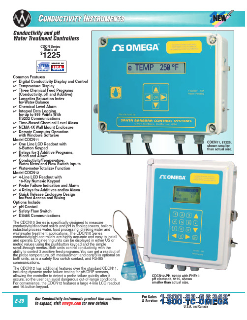
Omega CDCN系列电导仪产品说明书
CDSA-1413
23
1413 µmho/cm conductivity solution, 946 mL (1 qt)
CDSA-1500
10
1500 µmho/cm conductivity solution, 946 mL (1 qt)
Comes complete with operator’s manual and 3V lithium battery. Probes sold separately.
RS232, RS485 RS232, RS485
RS232 RS232 RS232, RS485 RS232, RS485
Keypad/Display 5-button/one line 5-button/one line 5-button/one line 5-button/one line 16-button/four line 16-button/four line 16-button/four line 16-button/four line
PHA-7
5
7.00 pH buffer solution, 500 mL (1 pt) bottle
PHA-10
5
10.00 pH buffer solution, 500 mL (1 pt) bottle
CDSA-45
10
45 µmho/cm conductivity solution, 946 mL (1 qt)
ߜ Three Chemical Feed Programs (Conductivity, pH and Additive)
ߜ Langelier Saturation Index for Water Balance
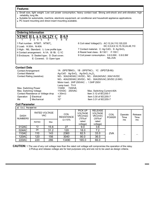
NT90TNLBSAC24VCB0.9中文资料
FeaturesSmall size, light weight. Low coil power consumption, heavy contact load. Strong anti-shock and anti-vibration, high reliability, long life.Suitable for automobile, machine, electronic equipment, air conditioner and household appliance applications.PC board mounting and direct insert mounting available.Ordering InformationNT90T H L A S DC12V C B 0.91 2 3 4 5 6 7 8 91 Part number :NT90T 、NT90T 22 Load :H:30A ;N:40A3 High :NIL: Standard ;L: Low profile type4 Contact arrangement :A:1A ;B:1B ;C:1C5 Enclosure :S: Sealed type ;D: Dust cover ; E: Covered ;O: Open type6 Coil rated Voltage(V):AC:12,24,110,120,220DC:3,5,6,9,12,15,18,24,48,1107 Contact material :C: Ag CdO ;S: Ag SnO 28 Resist heat class :B:130℃ F:155℃9 Coil power consumption :0.6:0.6W ;0.9:0.9W NIL:2VAContact DataContact Arrangement 1A SPSTBNO f 1B SPSTNC f 1C SPDT(B-M) Contact MaterialAg CdO Ag SnO 2 Ag SnO 2 In 2O 3Contact Rating (resistive)NO :30A/240VAC,14VDC ;NC :20A/240VAC ;30A/14VDC NO :40A/250VAC,30VDC ;NC :30A/250VAC,30VDC (0.9W)Motor load :2HP 250VAC ;1.5HP 250V Lamp load :TV-5Max. Switching Power1100W 7200VAMax. Switching Voltage110VDC 250VAC Max. Switching Current:40A Contact Resistance or Voltage drop አ30m Item 3.12 of IEC255-7Electrical 105Item 3.30 of IEC255-7Operation life Mechanical107Item 3.31 of IEC255-7Coil ParameterAC Coil ParameterRATED VOLTAGEVACDASH NUMBERSRATEDMaxCOIL RESISTANCE ±10%PICK UP VOLTAGE VAC(max)(75%of rated voltage)RELEASE VOLTAGE VAC(min)(30%of rated voltage)COIL POWEROperate Time ms Release Time ms012AC 1215.6279.0 3.6024AC 2431.212018.07.2110AC 110143236082.533.0120AC 120156304090.036.0220AC22028613490165.066.02VA __CAUTION : 1.The use of any coil voltage less than the rated coil voltage will compromise the operation of the relay.2.Pickup and release voltage are for test purposes only and are not to be used as design criteria.元器件交易网003-9003 3.9。
九星工业 97C 12V 24V 压力吹气机套装说明书
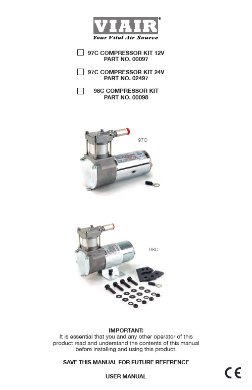
(Fig. 1) Air Compressor Kit Installation Parts List:
P/N 00097, P/N 02497, & P/N 00098
பைடு நூலகம்
98C - P/N 00098 (ONLY)
A
B
CDE
F
A. Ring Terminal (1pc)
B. Mounting Bolts (4pcs) C. Flat Washers (8pcs) D. Locking Washers (4pcs) E. Nuts (4pcs) F. Vibration Isolator (4pcs)
your vehicle or in the bed of your pickup, use a minimum 12 AWG positive lead wire for remote installation. (See wire gauge reference chart) 6. Do not mount compressor near areas where flammable liquids are stored.
agencies for all service and repairs. - Do not use this product in an area where it can fall or be pulled into water or other liquid. - Do not reach for this product if it has fallen into liquid. - Use this compressor with 12-volt (P/N: 00097, and 00098) or 24-volt (P/N: 02497)
电阻0.9 -回复
电阻0.9 -回复电阻是物理学中一个重要的概念,用于描述电流通过某些材料或器件时所遭遇的阻碍程度。
在本文中,我们将详细探讨电阻的定义、性质和应用。
首先,电阻是指当电流通过某个物体时遇到的阻碍。
通过导体时,电子在导体中自由移动,电流能够顺利通过,这样的导体称为低阻抗。
然而,对于一些非导体材料或特定的器件,电子的移动速度受到限制,电流通过时会遭遇一定程度的阻碍,这样的材料或器件称为高阻抗,并且具有电阻。
其次,电阻的大小可以通过一个参数来表示,即电阻值。
电阻值的单位是欧姆(Ω),用于表示电阻对电流的阻碍程度。
电阻值越大,电流通过的难度越大。
这种阻碍程度与材料的性质有关,如材料的导电性、温度、长度和横截面积等因素都会影响电阻值的大小。
一般情况下,金属材料具有低电阻值,而非金属材料则具有较高的电阻值。
电阻还具有一些重要的性质。
首先,电阻与电压和电流之间存在一定的关系,即欧姆定律。
欧姆定律表明,电阻值等于电压与电流之比。
这意味着,当给定电压时,电阻值越大,电流越小;反之,当给定电流时,电阻值越大,电压越高。
其次,电阻也会产生热量,这是因为电阻材料的电子在通过时与材料原子相互碰撞,从而产生能量损耗。
这种热量损耗可以通过欧姆定律和功率公式来计算。
电阻在电路中起着重要的作用。
它可以用来控制电路中的电流大小,同时也可以将电能转化为热能。
电阻还可以用来保护其他电子器件,防止电流过大而损坏电路。
在实际应用中,我们常常使用可调节电阻器来调节电路中的电流或电压,以满足特定的需求。
此外,电阻还被广泛应用于各种电子器件和电路设计中,如电子元器件选型、电路分析和设计等。
总的来说,电阻是描述电流通过材料或器件时所遭遇的阻碍程度的概念。
它具有一定的定义、性质和应用。
电阻的大小由电阻值表示,具体取决于材料的特性和电路设计需求。
了解电阻的概念和特性对于理解电路原理、设计和维护都是至关重要的。
- 1、下载文档前请自行甄别文档内容的完整性,平台不提供额外的编辑、内容补充、找答案等附加服务。
- 2、"仅部分预览"的文档,不可在线预览部分如存在完整性等问题,可反馈申请退款(可完整预览的文档不适用该条件!)。
- 3、如文档侵犯您的权益,请联系客服反馈,我们会尽快为您处理(人工客服工作时间:9:00-18:30)。
Features
Small size, light weight. Low coil power consumption, heavy contact load. Strong anti-shock and anti-vibration, high reliability, long life.
Suitable for automobile, machine, electronic equipment, air conditioner and household appliance applications.
PC board mounting.
Ordering Information
NT90 R H A S DC12V C B 0.9
1 2 3 4 5 6 7 8 91 Part number :NT90T 、NT90T 22 Terminal : R: without Pin 6;NIL: With Pin 6
3 Load :H:30A ;N:40A
4 Contact arrangement :1A:1A ;1B:1B ;1C:1C
5 Enclosure :S: Sealed type ;D: Dust cover ;
E: Covered ;O: Open type
6 Coil rated Voltage(V):AC:12,24,110,120,220
DC:3,5,6,9,12,15,18,24,48,1107 Contact material :C: Ag CdO ;S: Ag SnO 28 Resist heat class :B:130℃ F:155℃9 Coil power consumption :0.6:0.6W ;0.9:0.9W NIL:2VA Contact Data
Contact Arrangement
1A SPSTNO f 1B(SPSTNC)f 1C(SPDT(B-M))Contact Material
Ag CdO Ag SnO 2 Ag SnO 2 In 2O 3
Contact Rating (resistive)
NO : 30A/240VAC,14VDC; NC:20A/240VAC ;30A/14VDC NO :40A/250VAC,30VDC; NC:30A/250VAC,30VDC (0.9W)Motor load :2HP 250VAC ;1.5HP 250V Lamp load :TV-5
Max. Switching Power
1100W 7200VA Max. Switching Voltage
110VDC 250VAC Max. Switching Current:40A Contact Resistance or Voltage drop አ30m Item 3.12 of IEC255-7Electrical 105
Item 3.30 of IEC255-7Operation life Mechanical
107
Item 3.31 of IEC255-7
Coil Parameter
AC Coil Parameter
RATED VOLTAGE
VAC
DASH NUMBERS
RATED
Max
COIL RESISTANCE ±10%
PICK UP VOLTAGE VAC(max)(75%of rated voltage)RELEASE VOLTAGE VAC(min)(30%of rated voltage)
COIL POWER
Operate Time ms Release Time ms
012AC 1215.6279.0 3.6024AC 24
31.212018.0
7.2110AC 110143236082.533.0120AC 120156304090.036.0220AC
220
28613490165.066.0
2VA __
CAUTION : 1.The use of any coil voltage less than the rated coil voltage will compromise the operation of the relay.
2.Pickup and release voltage are for test purposes only and are not to be used as design criteria.
103
30.5×24.2×17 32.5×27.6×20.5 99312549.2 01311661.4
元器件交易网
003-9003 3.910
2.250.3005-9005 6.528
3.750.5006-90067.840
4.500.6009-900911.790 6.750.9012-900121
5.61609.00 1.2015-9001519.525010.25 1.5018-9001823.436013.50 1.8024-9002431.264018.00 2.4048-9004862.425603
6.00 4.8110-9001101431344582.5011.00.9
15
10
003-6003 3.915 2.250.3005-6005 6.542 3.750.5006-60067.860 4.500.6009-600911.7135 6.750.9012-6001215.62409.00 1.2015-6001519.537510.25 1.5018-6001823.454013.50 1.8024-6002431.296018.00 2.4048-6004862.4384036.00 4.8110-600
110
143
20167
82.50
11.0
0.6
15
10
CAUTION : 1.The use of any coil voltage less than the rated coil voltage will compromise the operation of the relay.
2.Pickup and release voltage are for test purposes only and are not to be used as design criteria.
Qualification inspection:
Perform the qualification test as specified in the table of IEC255-19-1 and minimum sample size 24.
Operation condition
Insulation Resistance 1000M min (at 500VDC)
Item 7 of IEC255-5Dielectric Strength Between contacts
Between contact and coil 50Hz 1500V 50Hz 2500V 4000V without Pin 6 Item 6 of IEC255-5
Item 6 of IEC255-5Shock resistance 200m/s 2 11ms
IEC68-2-27 Test Ea Vibration resistance 10~55Hz double amplitude 1.5mm IEC68-2-6 Test Fc Terminals strength 10N
IEC68-2-21 Test Ua1
Solderability
235 x 2 3x 0.5s IEC68-2-20 Test Ta method 1Ambient Temperature -55~100 -55~125 Relative Humidity 85% (at 40 )IEC68-2-3 Test Ca
Mass
27g Open type 30g
元器件交易网。