ISL9V3040P3中文资料
Eaton PDF34G0400P3DL 电源防御型号的产品说明说明书

Eaton PDF34G0400P3DLPower Defense Globally Rated 100% UL, Frame 3, Four Pole, 400A, 35kA/480V, PXR25 LSIG w/ Modbus RTU, CAM Link and Relays, Std Term Load Only (PDG3X4TA400)Eaton Power Defense molded case circuit breakerPDF34G0400P3DL 786679987773109.1 mm 257.1 mm 182.9 mm 7.68 kg Eaton Selling Policy 25-000, one (1) year from the date of installation of theProduct or eighteen (18) months from thedate of shipment of the Product,whichever occurs first.RoHS Compliant IEC 60947-2CCC MarkedProduct NameCatalog Number UPCProduct Length/Depth Product Height Product Width Product Weight WarrantyCompliancesCertifications400 AComplete breaker 3Four-pole (100% N)PD3 Global (100% UL) Class APXR 25 LSIGModbus RTU and CAM Link600 Vac600 V100% neutral protectionStandard Terminals Load Only35 kAIC at 480 Vac65 kAIC @240V (UL) 10 kAIC Icu @250 Vdc Eaton Power Defense PDF34G0400P3DL 3D drawingPower Xpert Protection Manager x32Consulting application guide - molded case circuit breakersPower Xpert Protection Manager x64StrandAble terminals product aidPower Defense technical selling bookletPower Defense brochurePower Defense molded case circuit breaker selection posterPower Xpert Release trip units for Power Defense molded case circuitAmperage RatingCircuit breaker frame type FrameNumber of poles Circuit breaker type ClassTrip Type CommunicationVoltage ratingVoltage rating - maxProtectionTerminalsInterrupt rating Interrupt rating range 3D CAD drawing package Application notesBrochuresCatalogsbreakersMolded case circuit breakers catalogCertification reportsPDG3 UL authorization 250-600a TMTUPDG3 UL authorization 100-400aInstallation instructionsPower Defense Frame 3 Breaker Instructions (IL012107EN).pdfMultimediaPower Defense Frame 5 Trip Unit How-To VideoEaton Power Defense for superior arc flash safetyPower Defense BreakersPower Defense Frame 6 Trip Unit How-To VideoPower Defense Frame 3 Variable Depth Rotary Handle Mechanism Installation How-To VideoPower Defense molded case circuit breakersPower Defense Frame 2 Variable Depth Rotary Handle Mechanism Installation How-To VideoSpecifications and datasheetsEaton Specification Sheet - PDF34G0400P3DLTime/current curvesPower Defense time current curve Frame 3 - PD3Warranty guidesSelling Policy 25-000 - Distribution and Control Products and ServicesWhite papersImplementation of arc flash mitigating solutions at industrial manufacturing facilitiesMolded case and low-voltage power circuit breaker healthIntelligent circuit protection yields space savingsIntelligent power starts with accurate, actionable dataMaking a better machineSafer by design: arc energy reduction techniquesMolded case and low-voltage breaker healthEaton Corporation plc Eaton House30 Pembroke Road Dublin 4, Ireland © 2023 Eaton. All Rights Reserved. Eaton is a registered trademark.All other trademarks areproperty of their respectiveowners./socialmedia。
西门子电源系列参数及尺寸信息说明书
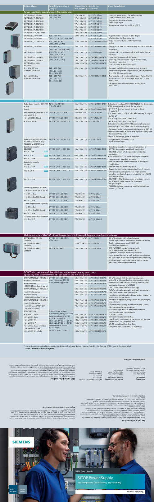
SITOP Power SupplyOrder overview Edition04//sitopSITOP Power SupplyTop integration. Top efficiency. Top reliability.Order overview SITOPRegulated Power Supplies, Expansion modules and DC UPS(range)mm (WxHxD)Siemens 1)Advanced power suppliesSITOP PSU8600 – The power supply system for digitalization and Industry 4.0PSU8600 1AC basic unit • 24 V DC/20 A/4 x 5 A NEW 100 – 240 V AC/110 – 220 V DC (85…275 V AC/99…275 V DC) 125 x 125 x 150 6EP3336-8MB00-2CY0• C ompact basic units with 1 or 4 outputs,each overload monitored • E xpandable without wiring effort: Up to 4 CNX8600 modules and 2 BUF8600/UPS8600 modules• E xpansion module for up to 36 outputs• C NX8600 8x2.5 A with NEC Class 2• O utputs individually adjustable:Voltage (4 - 28 V DC) and current• B uffer modules with electrolytic or double-layer capacitors to protect against brief power • U PS module with lead or lithium iron phosphate battery modules to protect against longer powerfailures• T wo Ethernet/PROFINET ports for optimumintegration in plants • I ntegrated Web server and OPC UA server • S imple engineering and comprehensive monitoring and diagnosis in TIA Portal• S upport of energy management due to capturing energy data and selectively switching off the outputs PSU8600 3AC basic unit 400-500 V 3 AC,(320 … 575 V 3 AC)• 24 V DC/20 A 80 x 125 x 1506EP3436-8SB00-2AY0• 24 V DC/20 A/4 x 5 A 100 x 125 x 1506EP3436-8MB00-2CY0• 24 V DC/40 A 125 x 125 x 1506EP3437-8SB00-2AY0• 24 V DC/40A/4 x 10 A 125 x 125 x 1506EP3437-8MB00-2CY0Modular system:Supply from basic unitPSU8600 via connection…System Clip Link“CNX8600 expansion module • 24 V DC/4 x 5 A 60 x 125 x 1506EP4436-8XB00-0CY0• 24 V DC/4 x 10 A 60 x 125 x 1506EP4437-8XB00-0CY0• 24 V DC/8 x 2.5 A NEC Class2100 x 125 x 1506EP4436-8XB00-0DY0BUF8600 buffer module• 100 ms/40 A 60 x 125 x 1506EP4297-8HB00-0XY0• 300 ms/40 A 125 x 125 x 1506EP4297-8HB10-0XY0• 4 s/40 A 60 x 125 x 1506EP4293-8HB00-0XY0• 10 s/40 A 125 x 125 x 1506EP4295-8HB00-0XY0UPS components • U PS module UPS86060 x 125 x 1506EP4197-8AB00-0XY0• B attery module BAT8600 Pb Energy exchange withUPS8600322 x 187 x 1106EP4145-8GB00-0XY0• B attery module BAT8600 LiFePO4322 x 187 x 1106EP4143-8JB00-0XY0SITOP PSU8200 – Technology power supply for demanding solutions24 V DC/5 A, PSU8200120/230 V AC(85 … 132/176 … 264 V AC)45 x 125 x 1256EP3333-8SB00-0AY0• Wide-range input• Efficiency levels of up to 95%• E xtra power feature (1.5 x I rated for 5 s/min for brief operational overload • P ower Boost (3 x I rated for 25 ms)for triggering protective equipment • S witchable characteristic curves forparallel operation and short-circuit protection • O peration status indicated by 3 LEDs •O utput voltage adjustable • 24 V power supply units expandable with add-on modules and DC UPS• 36 V and 48 V versions enable smallercross-sections of the load supply lines24 V DC/10 A, PSU820055 x 125 x 1256EP3334-8SB00-0AY024 V DC/5 A, PSU200M 120 – 230/230 – 500 V AC (85 … 264/176 … 550 V AC)70 x 125 x 1256EP1333-3BA1024 V DC/10 A, PSU200M 70 x 125 x 1256EP1334-3BA1024 V DC/20 A, PSU8200120/230 V AC (85 … 275 V AC/88 … 350 V DC)90 x 125 x 1256EP1336-3BA1024 V DC/40 A, PSU8200120/230 V AC (95 … 132/190 … 264 V AC)145 x 145 x 1506EP3337-8SB00-0AY024 V DC/20 A, PSU8200400 – 500 V 3 AC (320 … 575 V 3 AC)70 x 125 x 1256EP3436-8SB00-0AY024 V DC/40 A, PSU8200135 x 145 x 1506EP3437-8SB00-0AY036 V DC/13 A, PSU8200 70 x 125 x 1256EP3446-8SB10-0AY048 V DC/10 A, PSU820070 x 125 x 1256EP3446-8SB00-0AY048 V DC/20 A, PSU8200400 – 500 V 3 AC (340 … 550 V 3 AC)135 x 145 x 1506EP3447-8SB00-0AY0Standard power suppliesSITOP PSU6200 – The all-rounder power supply for a wide variety of applications12 V DC/2 A, PSU6200120 – 230 V AC/120 – 240 V DC (85 … 264 V AC/110 … 275 V DC)25 x 100 x 886EP3321-7SB00-0AX0• R obust wide range input AC and DC, 3-phase devicesalso applicable for continuous operation with2 phases• Space-saving, narrow design• High efficiency up to 96%• H igh overload capacity thanks to Extra-Power(1.5 x I nom for 5 s) and constant current behavior• P ermanent overload capacity (1.2 x I nom )up to 45 °C ambient temperature• Push-in terminals for fast connection• F rom 3.7 A: LED and signaling contact“DC OK”• F rom 24 V/10 A and 48 V/5 A: Diagnostics monitorfor overload and service life via LEDs Diagnosticsinterface signals all the relevant device and operatingdata. Active PFC for low reactive current component• E xpandable with all SITOP add-on modules24 V DC/1.3 A, PSU620025 x 100 x 886EP3331-7SB00-0AX024 V DC/2.5 A, PSU620040 x 100 x 886EP3332-7SB00-0AX012 V DC/7 A, PSU6200120 – 230 V AC/120 – 240 V DC (85 … 264 V AC/99 … 275 V DC)35 x 135 x 1256EP3323-7SB00-0AX024 V DC/3.7 A,NEC Class2, PSU620035 x 135 x 1256EP3333-7LB00-0AX024 V DC/5 A, PSU620035 x 135 x 1256EP3333-7SB00-0AX012 V DC/12 A, PSU6200120 – 230 V AC/110 – 240 V DC (85 … 264 V AC/85 … 275 V DC)45 x 135 x 1256EP3324-7SB00-3AX024 V DC/10 A, PSU620045 x 135 x 1256EP3334-7SB00-3AX048 V DC/5 A, PSU6200 NEW45 x 135 x 1256EP3344-7SB00-3AX024 V DC/20 A, PSU620070 x 135 x 1256EP3336-7SB00-3AX024 V DC/5 A, PSU6200NEW 400 – 500 V 3 AC(323 ... 576 V 3 AC/450 ... 600 V DC)35 x 135 x 1256EP3433-7SB00-0AX024 V DC/10 A, PSU6200 NEW 45 x 135 x 1556EP3434-7SB00-3AX024 V DC/20 A, PSU6200 NEW70 x 135 x 1556EP3436-7SB00-3AX0SITOP smart – Powerful standard power supply12 V DC/7 A, PSU100S 120/230 V AC(85 … 132/170 … 264 V AC)50 x 125 x 1206EP1322-2BA00• S pace-saving, slim design • P SU100S with automatic range switch over 120/230 V AC • E xtra-Power (1.5 x I rated for 5 s) for brief operational overload • P ermanent overload capacity (1.2 x I rated ) to 45 °C ambient temperature (24 V devices)• G reen LED and signaling contact …Output voltage OK”• A djustable output voltage up to 28.0 V DC or 15.5 V DC (12 V devices)• E xpandable with, redundancy module, selectivity/diagnostics module, buffer module and DC UPS12 V DC/14 A, PSU100S 70 x 125 x 1206EP1323-2BA0024 V DC/2.5 A, PSU100S 32,5 x 125 x 1206EP1332-2BA2024 V DC/5 A, PSU100S 50 x 125 x 1206EP1333-2BA2024 V DC/10 A, PSU100S 70 x 125 x 1206EP1334-2BA2024 V DC/20 A, PSU100S 115 x 145 x 1506EP1336-2BA1024 V DC/5 A, PSU300S 400 – 500 V 3 AC (340 … 550 V 3 AC)50 x 125 x 1206EP1433-2BA2024 V DC/10 A, PSU300S 70 x 125 x 1206EP1434-2BA2024 V DC/20 A, PSU300S 90 x 145 x 1506EP1436-2BA1024 V DC/40 A, PSU300S150 x 145 x 1506EP1437-2BA20Basic power suppliesSITOP lite – Cost-effective basic power supply24 V DC/2.5 A, PSU100L 120/230 V AC(93 ... 132/187 ... 264 V AC)32,5 x 125 x 1206EP1332-1LB00• F or industrial applications and basic requirements •N arrow width • G reen LED for “24 V OK”•A djustable output voltage 24 V DC/5 A, PSU100L 50 x 125 x 1206EP1333-1LB0024 V DC/10 A, PSU100L 70 x 125 x 1206EP1334-1LB0024 V DC/20 A, PSU100L100 - 240 V AC(85 ... 264 V AC/88 … 370 V DC)110 x 125 x 1256EP1336-1LB00LOGO!Power 4th generation – Flat power supply for distribution boards in LOGO! 8 design5 V DC/3.0 A 100 – 240 V AC(85 … 264 V AC/110 … 300 V DC)36 x 90 x 536EP3310-6SB00-0AY0•T he 4th generation with even more power in a smaller space: every performance class is 18 mm(1 modular width) narrower•N ew performance class only 18 mm wide • Wide-range AC and DC input• Voltage measuring point for output current•U p to 90% efficiency over entire load range • V ery low no-load losses of < 0.3%• C onstant current and power reserve for loads withhigh inrush currents• F lexible rail or wall mounting • G reen LED for “Output voltage OK”• A djustable output voltage• T emperature range -25 ... +70 °C 5 V DC/6.3 A 54 x 90 x 536EP3311-6SB00-0AY012 V DC/0.9 A 18 x 90 x 536EP3320-6SB00-0AY012 V DC/1.9 A 36 x 90 x 536EP3321-6SB00-0AY012 V DC/4.5 A 54 x 90 x 536EP3322-6SB00-0AY015 V DC/1.9 A 36 x 90 x 536EP3321-6SB10-0AY015 V DC/4.0 A 54 x 90 x 536EP3322-6SB10-0AY024 V DC/0.6 A 18 x 90 x 536EP3330-6SB00-0AY024 V DC/1.3 A 36 x 90 x 536EP3331-6SB00-0AY024 V DC/2.5 A 54 x 90 x 536EP3332-6SB00-0AY024 V DC/4 A72 x 90 x 536EP3333-6SB00-0AY0Power supply in SIMATIC-Design24 V DC/2.5 A, PM1207120/230 V AC(85 … 132/176 … 264 V AC)70 x 100 x 756EP1332-1SH71• C ompact Power Module for the S7-1200 with automatic range switchover24 V DC/2 A, PS307120/230 V AC(85 … 132/170 ... 264 V AC)40 x 125 x 1206ES7307-1BA01-0AA0• S ystem and load power supply for theS7-300 in new narrow design withautomatic range switchover24 V DC/5 A, PS30760 x 125 x 1206ES7307-1EA01-0AA024 V DC/10 A, PS30780 x 125 x 1206ES7307-1KA02-0AA024 V DC/3 A, PM1507 120/230 V AC(85 … 132 V/170 ... 264 V AC) 50 x 147 x 1356EP1332-4BA00• L oad power supply of S7-1500 in slimline design with automatic range switchoverand extra power (1.5 x I rated for 5 s/min)24 V DC/8 A, PM1507 75 x 147 x 1356EP1333-4BA0024 V DC/5 A, ET 200SP PS 120/230 V AC(85 … 132 V/170 ... 264 V AC)160 x 117 x 756EP7133-6AB00-0BN0• P ower supply for SIMATIC ET 200SP distributed I/O,flat design, with automatic range selection, extrapower (1.5 x I rated for 5 s/min), current monitor and plugs for 6 load circuits 24 V DC/10 A, ET 200SP PS 6EP7133-6AE00-0BN024 V DC/8 A, ET200pro PS400 – 480 V 3 AC (340 ... 550 V 3 AC)310 x 135 x 906ES7148-4PC00-0HA0• P ower supply in degree of protectionIP67 for electronics/sensors and load voltage for the SIMATIC ET200proDC/DC converter24 V DC/4 A, PSU340012 V DC (9 … 18 V DC)32 x 100 x 1006EP3133-0TA10-0AY0• S table output voltage from fluctuatingDC voltage• I deal for battery-operated applications such as driverless transport vehicles • P SU3400 in narrow metal housing,with reverse polarity protection and high efficiency up to 93.5%• P SU3400 24 V DC/24 V DC for compensating voltagelosses with long cables 12 V DC/8 A, PSU340024 V DC (14 … 32 V DC) startup from 18 V32 x 100 x 1006EP3123-0TA00-0AY012 V DC/15 A, PSU340042 x 125 x 1206EP3124-0TA00-0AY024 V DC/5 A, PSU340032 x 100 x 1006EP3133-0TA00-0AY024 V DC/10 A, PSU340042 x 125 x 1206EP3134-0TA00-0AY024 V DC/3.5 A,NEC Class 2, PSU340048 V DC (28 … 54 V DC) startup from 36 V32 x 100 x 1006EP3233-0TA10-0AY024 V DC/5 A, PSU34032 x 100 x 1006EP3233-0TA00-0AY024 V DC/10 A, PSU3400 42 x 125 x 1206EP3234-0TA00-0AY024 V DC/20 A, PSU400M600 V DC (300 … 900 V DC)startup from 340 V90 x 125 x 1256EP1536-3AA00• H igh input voltage, e.g. for operation at the DC link of drives • H igh efficiency of 95%1)C urrent ordering data plus terms and conditions of sale and delivery can be found in the Catalog KT10.1 and in the Internet at /industrymall。
ISL9V3040D3ST_NL中文资料
BVCES
Collector to Emitter Breakdown Voltage
390
420
450
V
BVECS BVGES ICER
Emitter to Collector Breakdown Voltage Gate to Emitter Breakdown Voltage Collector to Emitter Leakage Current
Electrical Characteristics TA = 25°C unless otherwise noted
Symbol Parameter Test Conditions Min Typ Max Units
Off State Characteristics
BVCER Collector to Emitter Breakdown Voltage IC = 2mA, VGE = 0, RG = 1KΩ, See Fig. 15 TJ = -40 to 150°C IC = 10mA, VGE = 0, RG = 0, See Fig. 15 TJ = -40 to 150°C IC = -75mA, VGE = 0V, TC = 25°C IGES = ± 2mA VCER = 250V, RG = 1KΩ, See Fig. 11 TC = 25°C TC = 150°C 370 400 430 V
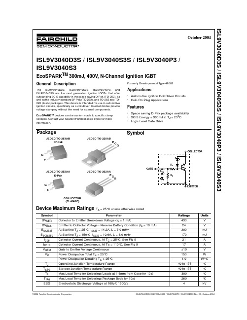
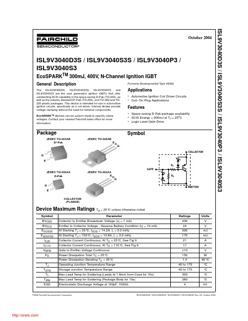
General Description
The ISL9V3040D3S, ISL9V3040S3S, ISL9V3040P3, and ISL9V3040S3 are the next generation ignition IGBTs that offer outstanding SCIS capability in the space saving D-Pak (TO-252), as well as the industry standard D²-Pak (TO-263), and TO-262 and TO220 plastic packages. This device is intended for use in automotive ignition circuits, specifically as a coil driver. Internal diodes provide voltage clamping without the need for external components. EcoSPARK™ devices can be custom made to specific clamp voltages. Contact your nearest Fairchild sales office for more information. Formerly Developmental Type 49362
TCL 电视产品文档说明书

DISCOVER A NEW EXPANSE OF COLOURL9H SERIES TRICHROMA LASER TVInspired by a world of incredible colour at a scale that makes everything feel brand new. The 3000 Lumen ultra-short throw projection TV features the TriChroma laser engine to reach 107% of the BT.2020 Colour space. L9H series is upgraded to support Dolby Vision, bringing incredibly vivid details to life. Premium features like Dolby Atmos® High-Speed HDMI, Filmmaker Mode, and a perfectly paired screen make the L9H the ultimate home entertainment upgrade.The triple colour laser light source generates three original colours (Red, Blue and Green) directly without a spinning colour wheel. Wider Colour Gamut and continuous improvements in the Trichroma laser engine and screen create images what the human eyes truly see in nature.107%BT.2020 Colour space1.07 BillionColoursMeet the L9H TriChroma Laser TVPremium X-FUSION™ Laser Light Source• Red + Green + Blue Lasers • 107% BT.2020 colour space • 3000 Lumens Brightness• 4K Resolution, 60Hz Refresh • Dolby Vision• 40W Dolby Atmos ® Sound• High-Speed HDMI with eARC • WiSA Ready • Google TVGet that childlike grin of excitement as you re-experience allyour favorites at a scale that makes everything feel brandnew. The massive 120-inch Laser TV display uses Ambient LightRejection technology to produce an incredibly bright picturethat’s enjoyable in any viewing environment, light or dark. This isyour true living room projection TV to take sports, streaming, andgaming to the next level.3000 Lumens. That’s right, the L9H shines with brilliance so allyour 4K HDR content hits those shimmering highlights, vibrantColours, and voluminous blacks that make everything pop off thescreen. And with incredible brightness uniformity across the entireprojection — no vignetting, no falloff — L9H is a shining wall of light.With built-in 40W Dolby Atmos sound, L9H is a big sound-stageupgrade over those tinny speakers in your last TV. Get clearspeech, thrilling highs, and booming lows without having toinvest in any extra gear. For the true audiophiles, high-speedHDMI with eARC allows for pass-thru of high-bitrate audio toyour surround sound system.120″Laser TV Display3000Lumens40WStereo Sound80%Ambient Light Rejection2,000,000:1Dynamic ContrastUltra High Speed HDMIwith eARCBig Screen ExperienceA Bright Picture in Any Room Powerful Sound2xUltra High Speed HDMI (1 with eARC)1xHDMI 2.01x 2xUSB1xDigital Audio Out 1xPortsAll product, product specifications, and data are subject to change without notice to improve reliability, function, design or otherwise. ©2023 Hisense Canada, All rights reservedHisense Canada Co., LtdUnit 1, 2550 Meadowvale Blvd, Mississauga, ON L5N 8C2 1-855-344-7367PhysicalConsole Dimensions 24” x 6.1” x 13.6” (W x H x D)Console Weight 24.7 lbsScreen Dimensions 104.6” x 60.4” x 1.4” (W x H x D)Screen Weight34.2 lbsOver box/Package Dimensions 69.1” x 25.7” x 20.1” (W x H x D)Over box/Package Weight110.3 lbsPictureProjection Size 120”Brightness3000 Lumens Resolution / Refresh Rate 4K@60Hz Colour Space 107% BT.2020Contrast Ratio 2,000,000:1 (dynamic)HDRHDR10, HLG, Dolby VisionLight Source Red + Green + Blue Trichroma Laser Laser Life 25,000+ Hours Throw Ratio 0.25:1Chipset0.47” DMDAudioAudio Output Power 40W (Stereo)Surround SoundDolby Atmos, Dolby DigitalSmart FeaturesSmart TV Platform Google TV (Google Certified)App StoreGoogle Play StoreStreaming Services Netflix, Disney+, HBO NOW, Hulu, Prime Video, SHOWTIME, Pandora, Sling TV, YouTube Voice Assistant Google AssistantWorks With Hey Google, Amazon Alexa Screen MirroringChromecast, AirPlay 2ConnectivityWi-Fi 802.11a/b/g/n/ac (Dual-Band, Wifi 6e)Bluetooth Yes Wired EthernetYesPowerPower Consumption 320W Standby Consumption <0.5W Power SupplyAC 120V, 60HzPortsHDMI2x HDMI 2.1 (ALLM), 1x HDMI 2.0HDMI ARC, CEC 1x (eARC on HDMI port 2)USB 1x USB 3.0, 1x USB 2.0RF Antenna 1x Ethernet (LAN)1x Digital Audio Output 1x Optical Analog Audio Output1xOther FeaturesNoise Reduction Yes Parental Controls Yes Closed Caption Yes Sleep Timer Yes Eye Safety Yes MEMCYes Remote FinderYesAccessoriesRemoteYes, voice remote with backlight Quick Start Guide / Manual QSG in box, Manual online Power Cable Yes Cleaning KitYesScreenScreen Size 120” diagonalTypeLenticular ALR (Ambient Light Rejecting)Resolution4K Ambient light obscuring ratio 85%Gain0.6Viewing Angle 150°Frame Fix (assembly required)Install Manual Yes Mounting Brackets Yes GlovesYesWarranty 2 Years limited warranty UPC/EANUPC: 888143014661EAN: 6942147488973Setup DiagramsH14 5/8”L111 7/8”W>90”H1>68”H261”Recommended TV stand height: <20”TECHNICAL SPECIFICATIONSLaser Model | 120L9H-DLT100C CONSOLETV STANDTV STANDH1(Minimum wall height)(mounting bracket holes)。
西门子仪表说明17
1.2
2
系统说明 ................................................................................................................................................. 2-1 2.1 2.2
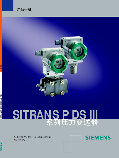
7MF4□33 系列 SITRANS P - DS III 压力/差压变送器
DS III 系列变送器,差压系列包括差压、流量、液位和绝压测量,压力系列包括压力、绝压测量。 产品手册
目录
目录
1 技术说明 ................................................................................................................................................. 1-1 1.1 应用范围 ........................................................................................................................................1-1 1.1.1 压力 .................................................................................................................................1-2 1.1.2 差压和流量 ......................................................................................................................1-2 1.1.3 液位 .................................................................................................................................1-2 1.1.4 绝压 .................................................................................................................................1-2 设计和工作原理 .............................................................................................................................1-2 1.2.1 设计 ..........................................................................................1-3 1.2.2 工作方式..........................................................................................................................1-5 1.2.2.1 电路原理 .........................................................................................................1-5 1.2.2.2 压力测量 .........................................................................................................1-6 1.2.2.3 差压和流量测量 ..............................................................................................1-6 1.2.2.4 液位测量 .........................................................................................................1-7 1.2.2.5 差压系列中的绝压测量 ...................................................................................1-7 1.2.2.6 压力系列中的绝压测量 ...................................................................................1-8 系统组成 ........................................................................................................................................2-1 SIMATIC PDM...............................................................................................................................2-2
P3056LS中文资料

G S
ABSOLUTE MAXIMUM RATINGS (TC = 25 °C Unless Otherwise Noted) PARAMETERS/TEST CONDITIONS Gate-Source Voltage Continuous Drain Current Pulsed Drain Current Avalanche Energy Repetitive Avalanche Energy Power Dissipation
元器件交易网
NIKO-SEM
N-Channel Logic Level Enhancement Mode Field Effect Transistor
P3056LS
TO-263
D
PRODUCT SUMMARY V(BR)DSS 25 RDS(ON) 50mΩ ID 12A 1. GATE 2. DRAIN 3. SOURCE
1 2 1
°C
SYMBOL RθJC RθJA RθCS
TYPICAL
MAXIMUM 2.6 60
UNITS
°C / W
0.6
Pulse width limited by maximum junction temperature. Duty cycle ≤ 1%
ELECTRICAL CHARACTERISTICS (TC = 25 °C, Unless Otherwise Noted) PARAMETER SYMBOL TEST CONDITIONS STATIC Drain-Source Breakdown Voltage Gate Threshold Voltage Gate-Body Leakage Zero Gate Voltage Drain Current V(BR)DSS VGS(th) IGSS IDSS VGS = 0V, ID = 250µA VDS = VGS, ID = 250µA VDS = 0V, VGS = ±12V VDS = 20V, VGS = 0V VDS = 20V, VGS = 0V, TJ = 125 °C 25 0.5 0.7 1.0 ±250 nA 25 250 µA V LIMITS UNIT MIN TYP MAX
Whirlpool IN1900S IX Cooker Hood 说明书

Instructions Manual Cooker HoodMODELIN1900S/IXINDEXEN RECOMMENDATIONS AND SUGGESTIONS (3)CHARACTERISTICS (4)INSTALLATION (5)USE (7)MAINTENANCE (8)your specific appliance.INSTALLATION • The manufacturer will not be held liable for any damages resulting from in-correct or improper installation. • The minimum safety distance between the cooker top and the extractor hood is 650 mm (some models can be installed at a lower height, please re-fer to the paragraphs on working dimensions and installation). • Check that the mains voltage corresponds to that indicated on the rating plate fixed to the inside of the hood. • For Class I appliances, check that the domestic power supply guarantees adequate earthing. Connect the extractor to the exhaust flue through a pipe of minimum diame-ter 120 mm. The route of the flue must be as short as possible. • Do not connect the extractor hood to exhaust ducts carrying combustion fumes (boilers, fireplaces, etc.). • If the extractor is used in conjunction with non-electrical appliances (e.g. gas burning appliances), a sufficient degree of aeration must be guaranteed in the room in order to prevent the backflow of exhaust gas. The kitchen must guarantee the entry of clean air.USE • The extractor hood has been designed exclusively for domestic use to elimi-nate kitchen smells. • Never use the hood for purposes other than for which it has been designed. • Never leave high naked flames under the hood when it is in operation. • Adjust the flame intensity to direct it onto the bottom of the pan only, making sure that it does not engulf the sides. • Deep fat fryers must be continuously monitored during use: overheated oil can burst into flames. • Do not flambè under the range hood; risk of fire • This appliance is not intended for use by persons (including children) with reduced physical, sensory or mental capabilities, or lack of experience and knowledge, unless they have been given supervision or instruction concern-ing use of the appliance by a person responsible for their safety. • Children should be supervised to ensure that they do not play with the appli-ance.MAINTENANCE • Switch off or unplug the appliance from the mains supply before carrying out any maintenance work. • Clean and/or replace the Filters after the specified time period (Fire hazard). • Clean the hood using a damp cloth and a neutral liquid detergent.The symbol on the product or on its packaging indicates that this product may not be treatedas household waste. Instead it shall be handed over to the applicable collection point for therecycling of electrical and electronic equipment. By ensuring this product is disposed of correctly,you will help prevent potential negative consequences for the environment and human health,which could otherwise be caused by inappropriate waste handling of this product. For moredetailed information about recycling of this product, please contact your local city office, yourhousehold waste disposal service or the shop where you purchased the product.ComponentsRef. Q.ty Product Components1 1 Hood Body, complete with: Controls, Light, Blower, Filters8 1 Directional Air Outlet grille9 1 Reducer Flange ø 150-120 mm10 1 Dumper ø150 mmelement20 1 ClosingRef. Q.ty Installation Components12a 4 Screws 4,2 x 44,412e 2 Screws 2,9 x 9,5DocumentationQ.tyManualInstruction1SNAP-ON FITTING• The hood can be installed either directly on the bottom surfaceof the wall units using snap-on side supports.• Cut a fitted opening in the bottom surface of the wall unit, asshown.• Insert the hood until the side supports snap into place.• Lock in position by tightening the screws Vffrom underneaththe hood.CLOSING ELEMENT• The space between the edge of the hood and the rear wall canbe closed by applying the element 20 provided, using thescrews supplied for this purpose.ConnectionsDUCTED VERSION AIR EXHAUST SYSTEMor 120mm, the choice of which is left to the installer.To install a ø 150 pipe• To install the dumper 10•(not supplied).To install a ø 120 pipe•the reducer flange 9 on the dumper 10.• Fix the pipe in position using sufficient pipe clamps(not supplied).• Remove any activated charcoal filters.RECIRCULATION VERSION AIR OUTLET• Cut a hole ø 125 mm in any shelf that may be posi-tioned over the hood.• Insert the reducer flange 9 on the hood body outlet.• Connect the flange to the outlet on the shelf over thehood by using a flexible or rigid pipe ø120 mm.• Fix the pipe in position using sufficient pipe clamps(not supplied).• Fix the air outlet grid 8 on the recirculation air outletby using the 2 screws 12e (2,9 x 9,5) provided.•inserted.ELECTRICAL CONNECTION• Connect the hood to the mains through a two-pole switch having a contact gap of at least 3 mm.• When opening the sliding carriage for the first time after installing the hood, pull it out briskly until it clicks.USEControl panelL Light Switches the lighting systemon and off.M Motor Switches the extractor motoron and off.V Speed Sets the operating speed ofthe extractor:1. Low speed, used for acontinuous and silent airchange in the presence oflight cooking vapour.2. Medium speed, suitablefor most operating condi-tions given the optimumtreated air flow/noiselevel ratio.3. Maximum speed, used foreliminating the highestcooking vapour emission,including long periods. LM Motor Switches the extractor motoron and off.V Speed Sets the operating speed ofthe extractor:1. Low speed, used for acontinuous and silent airchange in the presence oflight cooking vapour.2. Medium speed, suitablefor most operating condi-tions given the optimumtreated air flow/noiselevel ratio.MAINTENANCEGrease filters• The filters must be cleaned every two monthsof operation, or more frequently with heavy us-age, and can be washed in a dishwasher.• Remove the filters one at a time, after discon-necting the relative fastening elements.• Wash the filters, taking care not to bend them.Allow them to dry before refitting.• When refitting the filters, make sure that thehandle is visible on the outside.CLEANING MULTILAYER METAL GREASE FILTERS • The filters must be cleaned every two monthsof operation, or more frequently with heavy us-age, and can be washed in a dishwasher.• Release the filter retaining grill using the lateralsliding handles.• Remove the filter retaining clips.• Remove and wash the filters. Allow them to drybefore refitting.• Replace the filters on the grill, fix them in posi-tion using the filter retaining clips and close thefilter retaining grill.REPLACING SYNTHETIC GREASE FILTER • The filter is not washable and cannot be regen-erated, and must be replaced approximately e-very two months of use, or more frequentlywith heavy usage.• Release the filter holder frame using the lateralsliding handles.• Remove the fIlter retaining clips.• Replace the saturated synthetic filter.• Fix the new synthetic filter using the retainingclips and close the filter holder frame.Activated charcoal filter (Recirculation version)These filters are not washable and cannot be regenerated, and must be replaced approximately every 4 months of operation, or more frequently with heavy usage.REPLACING THE ACTIVATED CHARCOAL FILTER•Remove the metal grease filters •Remove the saturated activated charcoal filter as shown (A ). •Fit the new filters (B ). • Replace the metal grease filters.Lighting436004866_ver1。
IXFJ40N30资料

Symbol Test Conditions Maximum RatingsV DSS T J = 25°C to 150°C300V VDGR T J = 25°C to 150°C; R GS = 1 M W 300V V GS Continuous ±20V V GSM Transient ±30V I D25T C = 25°C40A I DM T C = 25°C, pulse width limited by T JM 160A I AR T C = 25°C 40A E AR T C = 25°C30mJ dv/dt I S £ I DM , di/dt £ 100 A/m s, V DD £ V DSS ,5V/ns T J £ 150°C, R G = 2 W P D T C = 25°C300W T J -55 ... +150°C T JM 150°C T stg -55 ... +150°C T L1.6 mm (0.062 in.) from case for 10 s 300°C Weight5gSymbol Test ConditionsCharacteristic Values(T J = 25°C, unless otherwise specified)min.typ.max.V DSS V GS = 0 V, I D = 250 m A 300V V GS(th)V DS = V GS , I D = 4 mA 24V I GSS V GS = ±20 V DC , V DS = 0±100nA I DSS V DS = 0.8 • V DSS T J = 25°C 200m A V GS = 0 VT J = 125°C1mAR DS(on)V GS = 10 V, I D = 0.5 I D2580m WPulse test, t £ 300 m s, duty cycle d £ 2 %HiPerFET TMPower MOSFETsN-Channel Enhancement ModeHigh dv/dt, Low t rr , HDMOS TM FamilyPreliminary data sheetFeatures•Low profile, high power package •Long creep and strike distances •Easy up-grade path for TO-220designs•Low R DS (on) HDMOS TM process•Rugged polysilicon gate cell structure •Unclamped Inductive Switching (UIS)rated•Low package inductance -easy to drive and to protect •Fast intrinsic Rectifier Applications •DC-DC converters•Synchronous rectification •Battery chargers•Switched-mode and resonant-mode power supplies •DC choppers •AC motor control•Temperature and lighting controls •Low voltage relaysAdvantages•High power, low profile package •Space savings •High power density98536 1/99)G = Gate, D = Drain,S = Source,TAB = Drain(TAB)G D SéSymbolTest ConditionsCharacteristic Values(T= 25°C, unless otherwise specified)characteristic curves are located in the IXFH 40N30 data sheet.。
ISL9V3040D3ST;ISL9V3040S3ST;ISL9V3040D3S;ISL9V3040S3S;中文规格书,Datasheet资料
BVCES
Collector to Emitter Breakdown Voltage
390
420
450
V
BVECS BVGES ICER
Emitter to Collector Breakdown Voltage Gate to Emitter Breakdown Voltage Collector to Emitter Leakage Current
Package Marking and Ordering Information
Device Marking V3040D V3040S V3040P V3040S V3040D V3040S Device ISL9V3040D3ST ISL9V3040S3ST ISL9V3040P3 ISL9V3040S3 ISL9V3040D3S ISL9V3040S3S Package TO-252AA TO-263AB TO-220AA TO-262AA TO-252AA TO-263AB Reel Size 330mm 330mm Tube Tube Tube Tube Tape Width 16mm 24mm N/A N/A N/A N/A Quantity 2500 800 50 50 75 50
Applications
• Automotive Ignition Coil Driver Circuits • Coil- On Plug Applications
Features
• Space saving D-Pak package availability • SCIS Energy = 300mJ at TJ = 25oC • Logic Level Gate Drive
Package
Eaton EGH3040FFB 电路保护器说明书

Eaton EGH3040FFBEaton Series G molded case circuit breaker, EG-frame, EG,Complete breaker, Fixed thermal, fixed magnetic trip, Three-pole, 40A, 600Y/347 Vac, 100 kAIC at 240 Vac, 65 kAIC at 480 Vac, 35 kAIC at 600Y/347 Vac, Bolt-on, 50/60 HzGeneral specificationsEaton Series G complete molded case circuit breakerEGH3040FFB 7866853818792.99 in 5.5 in3 in 3 lb Eaton Selling Policy 25-000, one (1) year from the date of installation of theProduct or eighteen (18) months from thedate of shipment of the Product,whichever occurs first.CE Marked CSA CertifiedIEC RatedUL ListedProduct NameCatalog Number UPCProduct Length/Depth Product Height Product Width Product Weight WarrantyCompliancesCertificationsSeries G100 kAIC at 240 Vac65 kAIC at 480 Vac35 kAIC at 600Y/347 Vac Complete breakerEGEG50/60 HzComplete breakerBolt-on600Y/347 Vac40 AFixed thermal, fixed magnetic Three-pole Application of Multi-Wire Terminals for Molded Case Circuit Breakers Application of Tap Rules to Molded Case Breaker TerminalsStrandAble terminals product aidComprehensive circuit protection for control panel applicationsMolded case circuit breakers providing higher levels of selective coordination product aidCurrent limiting molded case circuit breaker module product aidMulti-wire lugs product aidPower metering and monitoring with Modbus RTU product aidHigh performance operating handles for Series G circuit breakers product aidCircuit breaker motor operators product aidMotor protection circuit breakers product aidCurrent limiting molded case circuit breaker module for series G, JG and CLSeries G MCCB quick selectorPlug-in adapters for molded case circuit breakers product aidBreaker service centersMolded case circuit breakers catalogEaton's Volume 4—Circuit ProtectionEaton Specification Sheet - EGH3040FFBMOEM MCCB product selection guideNG and ND-Frame molded case circuit breakersSeriesInterrupt ratingTypeFrameCircuit breaker type Frequency ratingCircuit breaker frame type TerminalsVoltage rating Amperage RatingTrip TypeNumber of poles Application notesBrochuresCatalogsSpecifications and datasheetsEaton Corporation plc Eaton House30 Pembroke Road Dublin 4, Ireland © 2023 Eaton. All Rights Reserved. Eaton is a registered trademark.All other trademarks areproperty of their respectiveowners./socialmedia。
MOC3040中文资料

MIN TYP MAX UNITS 1.2 1.4 10 500 400 3.0 V µA nA V V V/µs
TEST CONDITION IF = 20mA VR = 6V VDRM = 400V (note 1 ) IDRM = 500nA ITM = 100mA ( peak )
Output
'X' SPECIFICATION APPROVALS
l
2.54 7.0 6.0 1.2
Dimensions in mm 1 2 3 6 5 4
VDE 0884 in 3 available lead form : - STD - G form
- SMD approved to CECC 00802 DESCRIPTION The MOC304_ Series are optically coupled isolators consisting of a Gallium Arsenide infrared emitting diode coupled with a monolithic silicon detector performing the functions of a zero crossing bilateral triac mounted in a standard 6 pin dual-in-line package. FEATURES l Options :10mm lead spread - add G after part no. Surface mount - add SM after part no. Tape&reel - add SMT&R after part no. l High Isolation Voltage (5.3kVRMS ,7.5kVPK ) l Zero Voltage Crossing l 400V Peak Blocking Voltage l All electrical parameters 100% tested l Custom electrical selections available
3040C使用说明书
DCAP-3040C(V3.0)差动保护装置使用说明书北京紫光测控有限公司BEIJING UNISPLENDOUR M&C CO. , LTD目录1 概述 (3)2装置主要功能配置 (3)3装置硬件资源配置 (4)4主要技术指标 (4)4.1 额定参数 (4)4.2 环境条件 (4)4.3 功率消耗 (5)4.4 热稳定性 (5)4.5 测控技术指标 (5)4.6 保护技术指标 (6)4.7 触点容量 (6)4.8 绝缘性能 (6)4.9 抗干扰能力 (7)5装置原理 (7)5.1 装置的构成 (7)5.2 保护原理说明 (8)6菜单及数据表格说明 (14)6.1 实时数据表 (14)6.2保护参数表 (16)6.3 通信数据表格 (19)6.4系统参数表 (23)6.5模拟量校准表 (26)7操作方法 (27)8装置结构及尺寸 (27)9装置典型接线图 (29)10箱后端子接线图 (30)1 概述DCAP3040C差动保护装置适用于变压器及其它构成四侧纵差保护的设备。
2 装置主要功能配置3 装置硬件资源配置4 主要技术指标4.1 额定参数交流电流额定值(In):5A,1A电源频率额定值:50Hz直流电源额定值:220V,110V 4.2 环境条件环境温度:工作:温度范围 -25~+55℃。
贮存:温度范围 -40~+70℃,在极限值下不施加激励量,装置不出现不可逆变化,温度恢复后,装置能正常工作。
大气压力:80~110KPa(相对海拔高度2Km及以下)相对湿度:最湿月的月平均最大相对湿度为90%,同时该月的月平均最低温度为25℃,且表面无凝露。
最高温度为40℃时,平均最大相对湿度不大于50%。
4.3 功率消耗交流电流回路:不大于0.5VA/相(额定电流下)直流回路:每个保护箱不大于15W(静态)或30W(动作)4.4 热稳定性长期运行2In,1.5Un短时过载20In,1s瞬时过载峰值50In,10ms4.5 测控技术指标(1)交流工频输入量a) 标称值电流:1A,5A;频率:50 Hz。
ICP DAS PM-3033-MTCP三相智能电能表快速入门指南说明书

PM-3033-MTCP3-Phase Smart Power MeterQuick Start GuideProduct Website:https:///pm_3033_mtcp1. IntroductionThe ICP DAS PM-3033-MTCP is a three phase smart power meter that communicates over Modbus TCP for energy monitoring and analysis. It allows users to have real time access to their power consumption by providing power measurements. It supports 10-500V, 1A or 5A and50/60Hz. The PM-3033-MTCP not only supports low voltage on the primary side of the power monitoring system but also the medium/high voltage on the secondary side. Based on the success of our previous smart power meters, this new PM-3033-MTCP no longer uses dedicated CT's, which helps users lower their implementation costs. Users can take direct input from the “secondary side 1A/5A” type CT's. It operates over a wide voltages input range of 10 ~ 500 VAC to ensure worldwide voltage compatibility. It supports Modbus TCP for easy integration with other I/O and SCADA system.2.1. Caution & WarningThe meter contains hazardous voltages, and should never be disassembled. Failing to follow this practice will result in serious injury or death. Any work on or near energized meters, meter sockets, or other metering equipment could induce a danger of electrical shock. It is strongly recommended that all work should be performed only by qualified industrial electricians and metering specialist. ICP DAS assumes no responsibility if your electrical installer does not follow the appropriate national and local electrical codes.ICP DAS assumes no liability for any damage resulting from the use of this product. ICP DAS reserves the right to change this manual at any time without notice. The information furnished by ICP DAS is believed to be accurate and reliable. However, no responsibility is assumed by ICP DAS for its use, not for any infringements of patents or other rights of third parties resulting from its use.2.2. Product Warranty & Customer SupportICP DAS warrants all products free from defects in material and workmanship for a period of one year from the date of shipping. During the warranty period, we will, at our position, either repair or replace any product that proves to be defective.To report any defect, please contact :+310-517-9888 or *******************2.2.1. Limitation of WarrantyThis warranty does not apply to defects resulting from unauthorized modification, misuse, or use for reason other than electrical power monitoring. The supplied meter is not a user-serviceable product.3. InstallationPlease use the soft dry clothes to clean the instrument.Please do not use any chemical or detergent or volatile solvents to clean the instrument, in order to avoid any possibility of the cover damage.3.1.•Dimension: 127mm(length)× 33mm(wide)× 105mm(high)•Please read this operation manual carefully before using.•Please re-confirm the measure position.•Reconfirm the RST (ABC) phase sequence of the power system.•PM-3133 series can be installed as rail mounting mode or embedded, no need to drill a hole or screw to fix it (rail mounting width can up to the length of 35 mm).•Meter auxiliary power for PM-3133 series is DC +12V ~+48V.3.2. Voltage Input1. PM-3033 series: Input Voltage up to 500V. For any higher Input Voltage large than 500V,please add the PT (power transformer), and Change PT RATIO setup.2. Confirm the RST (ABC) phase sequence.3.3. Current Input1. CT with secondary side output 1A/5A can be connected directly.2. The current direction must follow K-L marked on CT’s.3.4. ConnectionPlease firstly check the current input terminal. Make sure the arrow direction sign on Primary CT’s follows current flow direction(K→L).Note: it must be in the same direction.Connect the voltage input terminal N C B A. for PM-3033 series, in the three phase order as follows on N C B A.Attention please!! For 3P3W-2CT, connect in N C A phase sequence, do not connect phase B (Check the diagram).- LED IndicatorThe PM-3033 series has 2 LED to indicate the unit power status,communication, and power data calculation.RUN: Green, light up after communication ready. LED will flash when the unit is processing communication.PWR: Red, Power on LED always on.4. Communication。
30L30CTSPBF资料
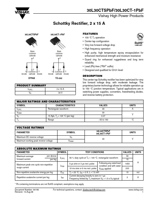
Document Number: 94196For technical questions, contact: diodes-tech@Schottky Rectifier, 2 x 15 A30L30CTSPbF/30L30CT-1PbFVishay High Power ProductsFEATURES•150 °C T J operation •Center tap configuration •Very low forward voltage drop •High frequency operation•High purity, high temperature epoxy encapsulation for enhanced mechanical strength and moisture resistance •Guard ring for enhanced ruggedness and long term reliability •Lead (Pb)-free (“PbF” suffix)•Designed and qualified for Q101 levelDESCRIPTIONThis center tap Schottky rectifier has been optimized for very low forward voltage drop, with moderate leakage. The proprietary barrier technology allows for reliable operation up to 150 °C junction temperature. Typical applications are in switching power supplies, converters, freewheeling diodes,and reverse battery protection.PRODUCT SUMMARYI F(AV) 2 x 15 A V R30 VBase common cathode2MAJOR RATINGS AND CHARACTERISTICSSYMBOL CHARACTERISTICS VAL U ESU NITS I F(AV)Rectangular waveform30A V RRM 30V V F 15 Apk, T J = 125 °C (per leg)0.37T JRange- 55 to 150°CVOLTAGE RATINGSPARAMETER SYMBOL 30L30CTSPbF 30L30CT-1PbFUNITS Maximum DC reverse voltageV R 30VMaximum working peak reverse voltageV RWMABSOLUTE MAXIMUM RATINGSPARAMETER SYMBOL TEST CONDITIONSVAL U ES UNITSMaximum average forward currentper deviceI F(AV)50 % duty cycle at T C = 140 °C, rectangular waveform 30A per leg15Maximum peak one cycle non-repetitive surge currentI FSM 5 µs sine or 3 µs rect. pulseFollowing any rated loadcondition and with rated V RRM applied145010 ms sine or 6 ms rect. pulse220Non-repetitive avalanche energy per leg E AS T J = 25 °C, I AS = 2 A, L = 7.5 mH15mJ Repetitive avalanche current per legI ARCurrent decaying linearly to zero in 1 µsFrequency limited by T J maximum V A = 1.5 x V R typical2A * Pb containing terminations are not RoHS compliant, exemptions may apply元器件交易网For technical questions, contact: diodes-tech@Document Number: 9419630L30CTSPbF/30L30CT-1PbFVishay High Power ProductsSchottky Rectifier, 2 x 15 ANote(1)Pulse width < 300 µs, duty cycle < 2 %ELECTRICAL SPECIFICATIONSPARAMETER SYMBOLTEST CONDITIONSVAL U ES UNITS Maximum forward voltage drop per legV FM (1)15 AT J = 25 °C 0.46V30 A 0.5715 A T J = 125 °C 0.3730 A0.50Maximum reverse leakage current per leg I RM (1)T J = 25 °C V R = Rated V R1.50mA T J = 125 °C350Maximum junction capacitance per leg C T V R = 5 V DC (test signal range 100 kHz to 1 MHz) 25 °C 1500pF Typical series inductance per leg L S Measured lead to lead 5 mm from package body 8.0nH Maximum voltage rate of change dV/dtRated V R10 000V/µs THERMAL - MECHANICAL SPECIFICATIONSPARAMETER SYMBOL TEST CONDITIONSVAL U ES UNITS Maximum junction andstorage temperature range T J , T Stg- 55 to 150°CMaximum thermal resistance, junction to case per leg R thJC DCoperation 1.5°C/W Maximum thermal resistance, junction to case per package 0.8Approximate weight 2g 0.07oz.Mounting torque minimum 6 (5)kgf · cm(lbf · in)maximum12 (10)Marking deviceCase style D 2PAK 30L30CTS Case style TO-26230L30CT-1元器件交易网Document Number: 94196For technical questions, contact: diodes-tech@30L30CTSPbF/30L30CT-1PbFSchottky Rectifier, 2 x 15 A Vishay High Power ProductsFig. 1 - Maximum Forward Voltage Drop CharacteristicsFig. 2 - Typical Values of Reverse Current vs.Reverse VoltageFig. 3 - Typical Junction Capacitance vs. Reverse VoltageFig. 4 - Maximum Thermal Impedance Z thJC Characteristics元器件交易网 For technical questions, contact: diodes-tech@Document Number: 9419630L30CTSPbF/30L30CT-1PbFVishay High Power ProductsSchottky Rectifier, 2 x 15 AFig. 5 - Maximum Allowable Case Temperature vs.Average Forward CurrentFig. 6 - Forward Power Loss CharacteristicsFig. 7 - Maximum Non-Repetitive Surge Current (Per Leg)Note(1)Formula used: T C = T J - Pd x R thJC ;Pd = Forward power loss = I F(AV) x V FM at (I F(AV)/D) (see fig. 6)元器件交易网元器件交易网Schottky Rectifier, 2 x 15 A Vishay High Power ProductsORDERING INFORMATION TABLELINKS TO RELATED DOCUMENTSDimensions /doc?95014Part marking information /doc?95008Packaging nformation /doc?95032SPICE model /doc?95287Document Number: 94196For technical questions, contact: diodes-tech@ Disclaimer Legal Disclaimer NoticeVishayAll product specifications and data are subject to change without notice.Vishay Intertechnology, Inc., its affiliates, agents, and employees, and all persons acting on its or their behalf (collectively, “Vishay”), disclaim any and all liability for any errors, inaccuracies or incompleteness contained herein or in any other disclosure relating to any product.Vishay disclaims any and all liability arising out of the use or application of any product described herein or of any information provided herein to the maximum extent permitted by law. The product specifications do not expand or otherwise modify Vishay’s terms and conditions of purchase, including but not limited to the warranty expressed therein, which apply to these products.No license, express or implied, by estoppel or otherwise, to any intellectual property rights is granted by this document or by any conduct of Vishay.The products shown herein are not designed for use in medical, life-saving, or life-sustaining applications unless otherwise expressly indicated. Customers using or selling Vishay products not expressly indicated for use in such applications do so entirely at their own risk and agree to fully indemnify Vishay for any damages arising or resulting from such use or sale. Please contact authorized Vishay personnel to obtain written terms and conditions regarding products designed for such applications.Product names and markings noted herein may be trademarks of their respective owners.元器件交易网Document Number: 。
三孔主开关3LD3040-1TK11产品说明书

Tender specifications /specifications
3LD3040-1TK11 Page 4/6
10/19/2017
Subject to change without notice © Copyright Siemens
60 mm 47 mm 380 mm Built-in unit fixed-mounted version
No Yes Yes 300 g
Environmental conditions Ambient temperature ● during operation / minimum ● during operation / maximum
48.4 43
60 24.1 70
48.4
4.5
61.3
351.2
46.4
31.3
32.8 34.4
Tuer/ Door/ Porte Puerta/ Porta/ Porta
3.2
Boden/ Base/ Plancher/ Base/ Pavimento/ Fundo
11.4
22.5 4.5
3LD3040-1TK11 Page 5/6
500 V 10 A 500 V
Suitability Suitability for use
● Main switch
Yes
● switch disconnector
Yes
● EMERGENCY OFF switch
Yes
● safety switch
Yes
● maintenance/repair switch
690 V 6 kV
Philips 81cm(32英寸)HD Ready LCD TV 32PFL3409 产品说明书

Philips LCD TV81 cm (32")HD Ready32PFL3409Clearly a smart choiceWith easy to use and future proof technology.Experience great picture and sound quality with this HD 1366 x 768p display. So easy to enjoy, with high quality standard, you can be sure that you make the right choice with this Philips Flat TV.Easy to connect and enjoy•2 HDMI inputs with Easylink for a full HD connection •PC-input allows you to use your TV as a PC monitor•Smart Picture and Smart Sound to personalize your viewing Vivid and razor sharp pictures•Digital Crystal Clear for detail depth and clarity •HD LCD display, with a 1366 x 768p resolution•Dynamic contrast 30000:1 for incredible rich black details •Active Control optimizes picture quality whatever the source •Native cinema mode for real movie experience Crisp and Clear sound•Incredible Surround for enhanced audio enjoyment •2 x 8W for superior sound clarity•Dynamic Bass Enhancement for cinematic soundHighlightsDigital Crystal ClearDigital Crystal Clear is a package of picture innovations that digitally adjusts and optimizes picture quality to optimal contrast, color and sharpness levels. It's like watching vivid cinema-like images.LCD display, 1366 x 768pThis WXGA display with state-of-the-art LCD screen technology gives you widescreen HD resolution of 1366 x 768p pixels. It produces brilliant flicker-free progressive scan pictures with optimum brightness and superb colors. This vibrant and sharp image will provide you with an enhanced viewing experience.Dynamic contrast ratio 30000:1You want the LCD flat display with the highest contrast and most vibrant images. Philips advanced video processing combined with unique extreme dimming and backlightboosting technology results in vibrant images. Dynamic Contrast will increase the contrast with excellent blacklevel and accuraterendition of dark shades and colors. It gives a bright, lifelike picture with high contrast and vibrant colors.Incredible SurroundIncredible Surround is an audio technology from Philips that dramatically magnifies the sound field to immerse you in the audio. Using state-of-the-art electronic phase shifting, Incredible Surround mixes sounds from left and right in such a way that it expands the virtual distance between the two speakers. This wider spread greatly enhances the stereo effect and creates a more natural sounddimension. Incredible Surround allows you to experience total surround with greater depth and width of sound, without the use of additional speakers.2 x 8W audio power2 x 8W for superior sound clarity2 HDMI inputs with EasyLinkEasyLink uses the HDMI CEC industry standard protocol to share functionalitybetween connected devices and the TV. With Easylink only one remote control is needed to operate main functionalities on your TV and connected devices. HDMI makes anuncompressed digital RGB connection from the source to the screen for the ultimate picture quality. HDMI uses HDCP copy protection. With 1 HDMI input on the back and 1 HDMI on the side of the TV you can connect multiple HD sources, for instance anHD settop box, a Blu-ray player, and Game Console or Digital Camcorder.PC input (HDMI and VGA)With PC input you can use your TV as a PC monitor either using a HDMI-DVI cable/converter (for digital signals) or VGA cable (for analog signals).Smart Picture and Smart SoundPhilips preset modes for Smart Picture and Smart Sound provide you with direct access via a single key on the remote control. You can select optimized picture and sound settings for the various picture and sound modes.Active ControlActive Control ensure that noise and sharpness improvements are continuously made at a rate of 60 times per second. By continually adjusting picture setting over 3,000 times per minute, Active Control Plus ensures that the viewing experience is optimized.True 24p playabilityMovies and many prime time TV programs are captured at 24 frames per second (24p).Without changing the frames processing of the film, the TV displays movie content exactly at 24 frames per second, hencing recreating the exact same motion effect film producers have intended.Dynamic Bass EnhancementBy using digital sound processing, DBEdynamically enhances the bass notes according to your personal wishes. Plus, since it is volume sensitive, the sound is always free from low-end distortion.Issue date 2023-07-30Version: 4.2.5EAN: 87 12581 47779 0© 2023 Koninklijke Philips N.V.All Rights reserved.Specifications are subject to change without notice. Trademarks are the property of Koninklijke Philips N.V. or their respective owners.SpecificationsPicture/Display•Aspect ratio: Widescreen•Diagonal screen size (inch): 32 inch •Diagonal screen size (metric): 81 cm •Panel resolution: 1366 x 768p •Brightness: 400 cd/m²•Picture enhancement: 3/2 - 2/2 motion pull down, 3D Combfilter, Active Control, ColorEnhancement, Digital Crystal Clear, Dynamic contrast enhancement, Jagged Line Suppression, Sharpness Adjustment, Dynamic Noise Reduction, 2D/3D noise reduction, 1080p 24/25/30Hz processing, 1080p 50/60Hz processing•Display screen type: LCD WXGA+ Active Matrix TFT•Response time (typical): 8 ms •Viewing angle: 178º (H) / 178º (V)•Screen enhancement: Semi-glareSupported Display Resolution•Computer formats: 640 x 480, 60, 72, 75, 85Hz, 800 x 600, 60, 72, 75, 85Hz, 1024 x 768, 60, 70, 75, 85Hz, 1280 x 768, 60Hz, 1280 x 1024, 60Hz, 1360 x 768, 60Hz, Via HDMI/DVI input,•Video formats: 480i, 60Hz, 480p, 60Hz, 576i, 50Hz, 576p, 50Hz, 720p, 50, 60Hz, 1080i, 50, 60Hz, 1080p, 24, 25, 30, 50, 60HzTuner/Reception/Transmission•Aerial Input: 75 ohm coaxial (IEC75)•Tuner bands: Hyperband, S-Channel, UHF, VHF •TV system: PAL B/G, PAL D/K •Number of Preset Channels: 99•Video Playback: NTSC, PALConvenience•Child Protection: Child Lock+Parental Control •Ease of Installation: Autostore, Fine Tuning, PLL Digital Tuning, Plug & Play, Program Name, Sorting •Ease of Use: Auto Volume Leveller (AVL),Graphical User Interface, On Screen Display, Side Control, Smart Picture, Smart Sound, EasyLink •Clock: On main display, Sleep Timer, Wake up Clock, Wake Up Timer•Connection Enhancement: Easy link•Screen Format Adjustments: 4:3, Movie expand 14:9, Movie expand 16:9, Subtitle Zoom, Super Zoom, Widescreen •Remote Control: TV•Remote control type: PF01A09B •Signal strength indication•Teletext: 1000 page Smart Text•On-Screen Display languages: Arabic, English, French, Thai, Traditional Chinese•Firmware upgradeable: Firmware upgradeable via USB•Teletext enhancements: 4 favourite pagesSound•Output power (RMS): 2 x 8W•Sound System: Mono, Nicam Stereo, Stereo •Sound Enhancement: Auto Volume Leveler,Dynamic Bass Enhancement, Incredible Surround, Treble and Bass ControlLoudspeakers •Built-in speakers: 2Connectivity•AV 1: Audio L/R in, YPbPr •AV 2: Audio L/R in, YPbPr •AV 3: Audio L/R in, CVBS in•EasyLink (HDMI-CEC): One touch play, EasyLink, System standby•Front /Side connections: HDMI v1.3, CVBS in, Audio L/R in, Headphone Out •HDMI 1:HDMI v1.3•Other connections: Monitor out, CVBS, L/R (cinch), PC-in VGA + Audio L/R inPower•Mains power: 110-240V; 50-60Hz •Ambient temperature: 5 °C to 40 °C •Power consumption: 120 W•Standby power consumption: 0.30 WAccessories•Included accessories: Table top stand, Power cord, Quick start guide, User Manual, Remote Control, 2 x AAA Batteries•User Manual: Arabic, English, French, Thai, Traditional ChineseDimensions•Set Width: 800 mm •Set Height: 534 mm •Set Depth: 80 mm•Product weight: 10.3 kg•Set width (with stand): 800 mm •Set height (with stand): 592 mm •Set depth (with stand): 235 mm •Product weight (+stand): 11.8 kg •Box width: 1018 mm •Box height: 668 mm •Box depth: 202 mm•Weight incl. Packaging: 16.5 kg•Wall mount compatible: 200 x 200 mm。
- 1、下载文档前请自行甄别文档内容的完整性,平台不提供额外的编辑、内容补充、找答案等附加服务。
- 2、"仅部分预览"的文档,不可在线预览部分如存在完整性等问题,可反馈申请退款(可完整预览的文档不适用该条件!)。
- 3、如文档侵犯您的权益,请联系客服反馈,我们会尽快为您处理(人工客服工作时间:9:00-18:30)。
Package Marking and Ordering Information
Device Marking V3040D V3040S V3040P V3040S Device ISL9V3040D3S ISL9V3040S3S ISL9V3040P3 ISL9V3040S3 Package TO-252AA TO-263AB TO-220AA TO-262AA Tape Width 16mm 24mm Quantity 2500 800 -
元器件交易网
ISL9V3040D3S / ISL9V3040S3S / ISL9V3040P3 / ISL9V3040S3
April 2003
ISL9V3040D3S / ISL9V3040S3S / ISL9V3040P3 / ISL9V3040S3
EcoSPARKTM 300mJ, 400V, N-Channel Ignition IGBT
©2003 Fairchild Semiconductor Corporation
ISL9V3040D3S / ISL9V3040S3S / ISL9V3040P3 / ISL9V3040S3 Rev. D2, April 2003
元器件交易网
ISL9V3040D3S / ISL9V3040S3S / ISL9V3040P3 / ISL9V3040S3
30 ±12 10K
±14 70 -
25 1 1 40 26K
V V µA mA mA mA Ω Ω
IECS R1 R2
Emitter to Collector Leakage Current Series Gate Resistance Gate to Emitter Resistance
On State Characteristics
25
20
20
15 TJ = 25°C TJ = 150°C 10
15 TJ = 25°C 10 TJ = 150°C 5 SCIS Curves valid for Vclamp Voltages of <430V 0 0 2 4 6 8 10
5 SCIS Curves valid for Vclamp Voltages of <430V 0 0 25 50 75 100 125 150 175 200
VCE(SAT) VCE(SAT) VCE(SAT) Collector to Emitter Saturation Voltage Collector to Emitter Saturation Voltage Collector to Emitter Saturation Voltage IC = 6A, VGE = 4V IC = 10A, VGE = 4.5V IC = 15A, VGE = 4.5V TC = 25°C, See Fig. 3 TC = 150°C, See Fig. 4 TC = 150°C 1.25 1.58 1.90 1.60 1.80 2.20 V V V
Package
JEDEC TO-263AB D²-Pak JEDEC TO-220AB E C G
Symbol
COLLECTOR
G E
R1 GATE
JEDEC TO-252AA D-Pak
JEDEC TO-262AA E
C G
R2
G E COLLECTOR (FLANGE)
EMITTER
Device Maximum Ratings TA = 25°C unless otherwise noted
Electrical Characteristics TA = 25°C unless otherwise noted
Symbol Parameter Test Conditions Min Typ Max Units
Off State Characteristics
BVCER Collector to Emitter Breakdown Voltage IC = 2mA, VGE = 0, RG = 1KΩ, See Fig. 15 TJ = -40 to 150°C IC = 10mA, VGE = 0, RG = 0, See Fig. 15 TJ = -40 to 150°C IC = -75mA, VGE = 0V, TC = 25°C IGES = ± 2mA VCER = 250V, TC = 25°C RG = 1KΩ, See T = 150°C C Fig. 11 VEC = 24V, See TC = 25°C Fig. 11 TC = 150°C 370 400 430 V
元器件交易网
ISL9V3040D3S / ISL9V3040S3S / ISL9V3040P3 / ISL9V3040S3
Typical Performance Curves (Continued)
ISCIS, INDUCTIVE SWITCHING CURRENT (A) RG = 1kΩ, VGE = 5V,Vdd = 14V ISCIS, INDUCTIVE SWITCHING CURRENT (A) 30 30 RG = 1kΩ, VGE = 5V,Vdd = 14V 25
General Description
The ISL9V3040D3S, ISL9V3040S3S, ISL9V3040P3, and ISL9V3040S3 are the next generation ignition IGBTs that offer outstanding SCIS capability in the space saving D-Pak (TO-252), as well as the industry standard D²-Pak (TO-263), and TO-262 and TO220 plastic packages. This device is intended for use in automotive ignition circuits, specifically as a coil driver. Internal diodes provide voltage clamping without the need for external components. EcoSPARK™ devices can be custom made to specific clamp voltages. Contact your nearest Fairchild sales office for more information. Formerly Developmental Type 49362
Dynamic CH) Gate Charge Gate to Emitter Threshold Voltage IC = 10A, VCE = 12V, VGE = 5V, See Fig. 14 IC = 1.0mA, VCE = VGE, See Fig. 10 IC = 10A, VCE = 12V VCE = 14V, RL = 1Ω, VGE = 5V, RG = 1KΩ TJ = 25°C, See Fig. 12 VCE = 300V, L = 500µHy, VGE = 5V, RG = 1KΩ TJ = 25°C, See Fig. 12 TJ = 25°C, L = 3.0 mHy, RG = 1KΩ, VGE = 5V, See Fig. 1 & 2 TC = 25°C TC = 150°C 1.3 0.75 17 3.0 2.2 1.8 nC V V V
Symbol BVCER BVECS ESCIS25 ESCIS150 IC25 IC110 VGEM PD TJ TSTG TL Tpkg ESD Parameter Collector to Emitter Breakdown Voltage (IC = 1 mA) Emitter to Collector Voltage - Reverse Battery Condition (IC = 10 mA) At Starting TJ = 25°C, ISCIS = 14.2A, L = 3.0 mHy At Starting TJ = 150°C, ISCIS = 10.6A, L = 3.0 mHy Collector Current Continuous, At TC = 25°C, See Fig 9 Collector Current Continuous, At TC = 110°C, See Fig 9 Gate to Emitter Voltage Continuous Power Dissipation Total TC = 25°C Power Dissipation Derating TC > 25°C Operating Junction Temperature Range Storage Junction Temperature Range Max Lead Temp for Soldering (Leads at 1.6mm from Case for 10s) Max Lead Temp for Soldering (Package Body for 10s) Electrostatic Discharge Voltage at 100pF, 1500Ω Ratings 430 24 300 170 21 17 ±10 150 1.0 -40 to 175 -40 to 175 300 260 4 Units V V mJ mJ A A V W W/°C °C °C °C °C kV
Applications
• Automotive Ignition Coil Driver Circuits • Coil- On Plug Applications
Features
• Space saving D-Pak package availability • SCIS Energy = 300mJ at TJ = 25oC • Logic Level Gate Drive