盘龙城公园地下空间概算对比表18.4.17
公共公园工程报价明细表

公共公园工程报价明细表
项目概述
本文档为公共公园工程的报价明细表,旨在提供工程项目的详细价格明细,方便相关人员对报价进行审查和评估。
工程项目信息
项目名称:公共公园工程
项目地址:(请填写具体地址)
工程内容:(请填写工程的具体内容和范围)
报价明细
以下是公共公园工程的报价明细,包括各项工程费用和材料费用的详细列示:
1.劳务费用
施工人员工资:(请列出各类施工人员的工资费用)
管理人员工资:(请列出各类管理人员的工资费用)
2.材料费用
建筑材料费用:(请列出需要使用的建筑材料及其费用)
园艺材料费用:(请列出需要使用的园艺材料及其费用)
3.设备费用
建筑设备租赁费用:(请列出需要租赁的建筑设备及其租赁费用)
园艺设备租赁费用:(请列出需要租赁的园艺设备及其租赁费用)
4.其他费用
水电费用:(请列出工程期间的水电费用估算)
运输费用:(请列出工程期间的运输费用估算)
其他费用:(请列出其他相关费用的估算)
总计
根据以上报价明细,公共公园工程的总费用为:(请填写总费用金额)
以上报价明细仅供参考,具体费用可能会因为实际情况发生变化。
如有需要,我们随时可以提供详细的费用计算和报价说明。
如有任何疑问,请随时与我们联系。
谢谢!
注意:本文档中的所有价格仅供参考,请在实际报价时进行确认。
武汉盘龙城遗址公园市政工程

武汉盘龙城遗址公园市政工程
盘龙城遗址核心区本体保护市政工程昨天正式开工。
据市政工程师介绍将有领导来参加开工仪式,国家文物局副局长童明康专程来汉出席开工仪式,市长唐良智宣布工程正式开工,副市长刘英姿主持开工仪式。
盘龙城遗址是第三批全国重点文物保护单位,是长江中游地区首次发现的商代早期城市遗址,距今3500年,也是迄今我国发现的同时期保存最好的城址之一。
盘龙城作为武汉地区最早出现的城市,被誉为“武汉城市之根”,是当之无愧的武汉文化之魂。
我市将在盘龙城遗址上建设国家考古遗址公园。
记者昨天在盘龙城遗址保护总体规划图上看到,未来的盘龙城国家考古遗址公园主要由遗址博物馆展示区、遗址本体展示区和遗址生态环境区三个部分组成,将环抱盘龙湖,毗邻府河,依山傍水。
未来建成的盘龙城国家考古遗址公园,将以保护遗址本体为主要目的,兼顾遗址展示、生态保护、环境整治、教育科研、旅游休闲等功能,打造商文化特征突出、功能复合、可持续发展的城市郊野公园。
国家文物局副局长童明康建议,在做好盘龙城考古遗址公园时,强调原生态保护,更加注重大遗址保护和考古遗址公园的公益性。
据悉,本体市政工程预计于明年完工,盘龙城遗址博物馆将于2015年建成,盘龙城遗址公园有望在2017年建成开放。
盘龙城考古遗址公园监理中标公示

盘龙城考古遗址公园监理中标公示
【最新版】
目录
1.盘龙城考古遗址公园
2.监理中标公示
3.项目概括
4.中标单位及联系方式
5.中标金额
6.公示时间
7.相关附件
正文
盘龙城考古遗址公园位于我国湖北省武汉市,是一处具有重要历史价值的文化遗址。
为了保护和发掘这一文化遗产,相关部门对该遗址进行了一系列的考古发掘和保护工作。
近期,盘龙城考古遗址公园发布了监理中标公示,对项目的监理进行公开招标。
根据公示内容,我们可以了解到项目概况如下:项目内容包括遗址保护区的日常巡查、维护、保养及突发事件的应急处理等。
此次招标的监理单位将负责对遗址的保护工作进行全程监理,确保遗址得到有效保护。
经过严格的评审程序,中标单位为“武汉华宇建设监理有限公司”。
中标单位具有丰富的监理经验,曾经承担过多个类似项目的监理工作。
中标单位的联系方式为:武汉市江汉区建设大道 386 号,联系电话:。
此次中标金额为 800 万元人民币,中标单位将在合同签订后按照约定履行监理职责。
公示期为自发布之日起 5 个工作日,如有异议,请在公示期内向招标方提出。
同时,公示还附带了相关附件,包括中标单位的资质证书、业绩表、评审报告等,以便公众了解中标单位的具体情况。
总之,盘龙城考古遗址公园监理中标公示的发布,意味着遗址保护工作将得到进一步加强。
《湖北省城市地下综合管廊工程维护消耗量定额及全费用基价表》宣贯资料

湖北省建设工程标准定额管理总站
• (三)编制过程 • 1.第一阶段:前期准备工作,成立编制组,确定编制方案 • 2.第二阶段:项目设置与确定 • 3.第三阶段:消耗量调整及初稿的确定 • 4.第四阶段:征求意见及审查 • 5.第五阶段:报批稿的形成
-
-
五
通风系统
-
-
六
给排水系统
-
-
七
标识系统
-
-
八
其他
增加除锈和刷油相应项目
湖北省建设工程标准定额管理总站
•
序号
章节项目
第三章 一 二 三
第四章 一 二 三 四
保洁 结构设施保洁
井底清泥 排水沟清泥
检查检测 日常检查 常规定期检查 结构定期检查 有害气体检测
项目内容 增加项目
全部新增 全部新增 全部新增
• (5)本定额的费率根据不同章节执行相应取费标准,详见
湖北省城市地下综合管廊工程维护取费表。
湖北省建设工程标准定额管理总站
• (二)总说明 • 1.本定额按照城市地下综合管廊工程维护的施工条件、省内
大多数维护管理企业采用的维护方法、维护施工机械设备和 合理的劳动组织及工期进行编制。
• 2.本定额已综合考虑城市地下管廊维护工程中的工程量少、
• 1.中华人民共和国住房和城乡建设部已颁布《城市
地下综合管廊工程维护消耗量定额》ZYA 141(01)-2018。
• 2.湖北省住房建设和城乡建设厅发布《湖北省房屋
建筑与装饰工程消耗量定额及全费用基价表》10项
3 定额。
• 3.国家、湖北省颁布的营改增政策文件。
湖北省建设工程标准定额管理总站
公共场所一期项目工程造价指标分析
公共场所一期项目工程造价指标分析文档简介案例工程以场所功能为需求,进行景观升级改造。
其中包括花园大门、主入口广场、主园路及园桥、中心湖、主要地形土方、厕所、停车场、水边林荫平台、基础绿化、水电配套等;儿童活动区建设小型儿童游乐区和非机动儿童游乐区,同步进行绿化升级改造及进一步完善公园配套基础设施。
目录1造价指标案例一:某花园一期工程 (3)1.1工程概况 (3)1.2工程特征 (3)1.3指标分析汇总表 (3)2造价指标案例一:某花园儿童活动区(一期)工程 (5)2.1工程概况 (5)2.2工程特征 (5)2.3指标分析汇总表 (6)1造价指标案例一:某花园一期工程1.1工程概况序号项目名称内容1工程名称某花园一期工程2工程地点广东省-广州市3工程分类城市园林工程4单位价值5建筑内容大门、主入口广场、主园路及园桥、中心湖、主要地形土方、厕所、停车场、水边林荫平台、基础绿化、水电配套等6价格取定期2014年第二季度1.2工程特征序号特征项特征值1绿化种植面积(m2)23000 2每平方米工程造价(元/m2)499.06 3草地覆盖面积(m2)230001.3指标分析汇总表序号工程及费用名称技术经济指标单位数量单位价值占总投资百分比%一第一部分工程费用81.69%一园建部分0.00% 1主园路(砼)m246502508.27% 2广场铺装(花岗岩)m25220120 4.46% 3植草砖停车场m21920100 1.37% 4挖中心湖(含湖基底处理)m2207978011.84%小计25.94%二建筑部分0.00% 1管理用房m245025008.01% 2厕所座1262500 1.87%3大门建筑座11200000.85%小计10.73%三绿化部分0.00% 1绿化升级改造m22300015024.55%小计24.55%四土方部分0.00% 1堆地形土方m225000407.12%小计7.12%五水电部分0.00% 1景观照明工程m24690318 6.01% 2绿化给排水工程m246903227.34%2造价指标案例二:某花园儿童活动区(一期)工程2.1工程概况序号项目名称内容1工程名称某花园儿童活动区(一期)工程2工程地点广东省-广州市3工程分类城市园林工程4单位价值5建筑内容按照不同年龄层次儿童需求,先行建设小型儿童游乐区和非机动儿童游乐区;同步进行绿化升级改造及进一步完善公园配套基础设施6价格取定期2014年第二季度2.2工程特征序号特征项特征值1总建筑面积(平方米)48000 2地上面积(平方米)3地下面积(平方米)4建安工程造价(万元)1994.4 5每平方米造价415.5 6结构类型7总层数(层)8地上层数(层)9地下层数(层)10建筑总高度(米)11首层层高(米)12标准层高(米)13装修标准(元/平方米)14外墙形式15是否含电气工程是16是否含给排水工程是17是否含通风空调工程否18是否含消防工程是19是否含弱电工程是20是否含变配电工程否21是否含燃气工程否22是否含道路工程是23是否含园林绿化工程是2.3指标分析汇总表序号工程及费用名称技术经济指标单位数量单位价值占总投资百分比%一第一部分工程费用76.90% 1一级园路m21200450 2.08% 2二级园路m23003000.35% 3三级园路m26002000.46% 4汀步m2502000.04% 5铺装平台m23000350 4.05% 6管理房m2170-0.00% 7厕所座3150000 1.74% 8休息亭座5500000.96% 9休息廊座575000 1.45% 10营养餐厅座1- 1.54% 11其他休憩建筑m24601900 3.37% 12儿童小型机动设施游乐区m210000-0.00% 13儿童非机动设施游乐区m2800095029.30% 14水体m215001500.87% 15土方工程m32000040 3.08% 16绿化m22200023019.51% 17给排水宗1- 2.31% 18电气宗1- 5.78%。
盘龙城遗址公园绿化特色分析及其发展对策

盘 龙 城 遗 址 公 园 目前 还 处 于文 物 保 护 和 挖 掘 阶段 , 仍 然 有 大 部 分 考 古 挖 掘 工 作 没 有 完 成 ,如 李 家 嘴 、杨 家 湾 和 小 嘴 等 正 在 考 古 勘 探 中 。出 于对 文 物 保 护 的考 虑 , 对 于遗 址 核 心 区 (紫 线 范 围 内 )土 层 的扰 动 需 控 制 在 表 层 土 20 cm 以 内 ,整 个 工 程 施 工 建 设 中 ,栽 植 前 整 地 、土 壤改 良和树 穴 准 备 工 作 均 采 取 人 工 完 成 ,大 型机 械一 律 不 得 进 入 。
由 于乔 木 栽 植 时 ,需 满 足 土 球 直 径 为 胸 径 6~ 1O 倍 ,土球 厚 底 需 达 到 土 球 直 径 的 2/3 ],现 场 所 有 乔 木 栽植 均 采 用 培 土起 垄 栽 植 ,以达 到 对 遗 址 核 心 区 内 文 物 保 护 的 目的 。这 种 做 法 对 景 观 有 一 定 干 扰 和 影 响 ,但 这 也 正 是 遗 址 公 园 绿 化 栽植 需 遵循 的重 要 原 则 之 一 。 3.3 绿 化 功 能 分 区 明确
1 引 言
过 多 的构 树 等 杂 木 ,保 留 了具 有 丰 富 特 色 的 苦 楝 、合 欢 、 枫 杨 等 乡土 树 种 ,保 证 了宫 殿 区 和 考 古 探 方 等 核 心展 陈
国 家 考 古 遗 址 公 园 绿 化 的研 究 尚 属空 白 ,目前 遗 址 公 园 的 绿 化 原 则 和 方 法 主 要 还 是 以 传 统 园 林 和 景 观 设 计 学 为 依 托 ],但 考 古 遗 址 公 园 绿 化 的 主 要 目 的是 对 文 化 遗 产 保 护 及 历 史 环 境 保 护 ,达 到 文 化 、生 态 和 自然 的 统 一 融 合 。 旨在 通 过 对 已 建 成 的 武 汉 市 盘 龙 城 遗 址 本 体 保 护 展 示 及 配 套 工 程 的绿 化 特 色 分 析 ,发 现 和 总结 遗 址 公 园绿 化 存 在 的 问 题 ,结 合 文 化 遗 产 保 护 、风 景 园 林 规 划 、城 市 绿 化 等 相 关 理 论 和 经 验 ,期 望 对 正 在 实 施 的 盘 龙 城遗 址 核 心 区 环 境 整 治 项 目绿 化 和 遗 址 博 物 馆 绿 化 的 实施 提 供 因地 制 宜 的设 计 理 念 和 种 植 的对 策 ,为 其 他 地 区 的 遗 址公 园 绿化 建 设 提 供 借 鉴 意 义 。
湖北省城市地下综合管廊工程消耗量定额及全费用基价表(2018)

十一、本定额中人工、材料、机械台班价格的管理ꎬ按« 湖北省建筑安装工程费用定额» (2018) 规定执
行ꎮ
十二、施工与生产同时进行、有害身体健康的环境中施工时的降效增加费ꎬ本定额未考虑ꎬ发生时另
行计算ꎮ
十三、本定额适用于海拔 2000m 以下地区、地震烈度Ⅶ度以下地区ꎮ 超过上述情况时ꎬ可结合具体
情况调整ꎮ
场加工地点)至操作(或安装)地点的施工场内运输损耗、施工操作损耗、施工现场堆放损耗等ꎬ规范( 设
计文件) 规定的预留量、搭接量不在损耗率中考虑ꎮ
4.定额列出的材料价格是从材料来源地(或交货地) 至工地仓库( 或存放地) 后的出库价格ꎬ由材料
原价( 或供应价) 、运杂费、运输损耗费、采购及保管费组成ꎮ
身ꎮ
湖北 10.凡本说明未尽事宜ꎬ详见各章说明和附录ꎮ
������3������
站 总 理 管 额 定 准 标 程 工 设 建 省 北 湖
目 录
第一章 土石方工程
说明������������������������������������������������������������������������������������������������������������������������������������������������������������������������������������������������������������������������������������������������������������������������������������������ (3) 工程量计算规则 ������������������������������������������������������������������������������������������������������������������������������������������������������������������������������������������������������������������������������������������������������ (6) 一、土方工程 ������������������������������������������������������������������������������������������������������������������������������������������������������������������������������������������������������������������������������������������������������������ (9) 1.人工土方 ������������������������������������������������������������������������������������������������������������������������������������������������������������������������������������������������������������������������������������������������������������ (9)
市政工程设施养护维修估算指标

城镇市政设施养护维修工程投资估算指标修订稿主编单位:中国市政工程协会市政设施管理专业委员会批准机关:中华人民共和国住房和城乡建设部目录总说明…………………………………………………第一章道路工程第一节说明第二节道路工程单位实物量指标第三节计算举例第二章排水工程第一节说明第二节排水工程单位实物量指标第三节计算举例第三章结构工程第一节说明第二节结构工程单位实物量指标第三节计算举例第四章照明工程第一节说明第二节照明工程单位实物量指标第三节计算举例附录一:主要设施小修维护率附录二:主要材料计量单位、规格及损耗率表附录三:主要机械设备及规格表总说明一、《城镇市政设施养护维修工程投资估算指标》(以下简称估算指标),根据建标造函[2007]92号文的要求,为更好的适应我国城市化进程发展,确保市政设施的社会化服务水平,有效地保证市政设施的完好及正常使用,合理确定城镇市政设施年度养护维修管理经费而进行编制的。
二、本估算指标适用范围:城镇范围内的道路、桥梁、排水、照明等市政设施小修养护维修和日常运行管理。
三、编制估算指标的主要依据:1. 《全国市政工程统一劳动定额》(1997);2. 《全国市政工程设施养护维修估算指标》(1994);3. CJJ36-2006 《城镇道路养护技术规范》;4. CJJ6-1985 《排水管道维护安全技术规程》;5. CJJ68-2007 《城镇排水管渠与泵站维修技术规程》;6. 全国《城市排水许可管理办法》及省市《排水管理条例》;7. CJJ99-2003 《城市桥梁养护技术规范》;8. 《城市桥梁检测和养护维修管理办法》(中华人民共和国建设部令第118号);9. CJJ89-2001 《城市道路照明工程施工及验收规程》;10. 中华人民共和国建设部第104号令,关于修改《城市道路照明设施管理规定》;11.国务院第198号令《城市道路管理条例》;12. 中华人民共和国建设部《市政工程投资估算指标2007》13. 部分省、市主管部门颁发的市政设施养护标准及操作规程;14. 部分省、市管养部门制定的《养护定额》,《维修定额》;15. 部分省、市管养部门近三年的统计资料四、本估算指标的作用:1. 是市政设施管理养护部门编制年度养护维修管理经费和上级主管部门审批、检查市政设施管养资金投入与运营情况的主要依据。
Robot Navigation Using Panoramic Landmark Tracking
Robot Navigation Using Panoramic Landmark TrackingMark Fiala and Anup BasuDepartment of Computing Science,University of Alberta,Edmonton,Alberta,Canada T6G2E8fiala,anup@cs.ualberta.ca.http://www.cs.ualberta.ca/fiala/panotrack/AbstractA vision based navigation system is presented for deter-mining a mobile robot’s position and orientation usingpanoramic imagery.Omni-directional sensors are useful in obtaining afield of view,permitting objects in the vicinity of a robot to be imaged simultaneously.Recogniz-ing landmarks in a panoramic image from an a priori model of distinct features in an environment allows a robot’s lo-cation information to be updated.A system is shown for tracking vertex and line features for omni-directional cam-eras constructed with catadioptric(containing both mirrors and lenses)optics.With the aid of the Panoramic Hough Transform,line features can be tracked without restricting the mirror geometry to that which satisfies the single view-point criteria.Two paradigms for landmark tracking are ex-plored,with experiments shown with synthetic and real im-ages reported.A working implementation on a mobile robot is shown.1IntroductionOne fundamental component for an autonomous mobile robotic platform is to determine its position and orientation with respect to its environment.Example systems use sonar sensors,motor odometry and radio beacons[3].A passive vision-based system would be very advantageous,and in-crease the practical utility and scalability of mobile robotics. Hager and Rasmussen define a framework for robot navi-gation using standard perspective cameras[11,14].If this vision system was panoramic,objects all around the robot could be used forfinding and updating the position estimate.The paradigm of an agent translating along a horizontal plane and rotating about a vertical axis,in a space defined andfilled with rectilinear polyhedral objects is a reasonable assumption for a mobile robot operating in a man-made en-vironment.Indeed most indoor scenes can be well defined by the primitives of horizontal and vertical lines,corners where such line edges meet,and rectangular surfaces withonly horizontal and vertical edges.Thus we define a framework for creating a passive vision-based navigation system as that of iteratively predict-ing the location of a prominent geometric feature composedof horizontal and vertical lines,tracking the location of the feature in a panoramic image,and aggregating a number of such observations to arrive at a new position and orientationestimate.We are restricting the problem to that of a mobile agent with motion possible only along the horizontal axis,reducing the dimensions of navigation data to three,two for position and one for orientation.The presence of an a pri-ori model of prominent landmarks for predicting trackablefeatures is assumed.Omni-directional viewing would require many standard narrowfield of view cameras,or one panoramic camera.A catadioptric optical system is one that uses both lens andmirror components in the optical path,and can be used to capture afield of view around a mobile robot.Basu [2],and others[13,16,17,4,5]have demonstrated suchcatadioptric panoramic systems.An example is shown in Fig.1(left).If a convex,radially symmetric mirror,lens(es) or pinhole and a planar image plane are all mounted along one vertical axis,then a panoramic view can be captured as shown in Fig.1(right).Such a system has the advan-tages of processing only one image,and with this image be-ing continuous,not having to deal with discontinuities at the boundaries of views as a ring of conventional cameras would introduce.Such a view permits the capture of a panoramic view,but with the added challenge offinding and tracking objects in a non-perspective projection.Panoramic catadioptric cameras are not necessarily even cylindrical projections,and locat-ing and tracking features(especially lines)introduces chal-lenges from tracking in more traditional perspective view imagery.Thefirst positioning method demonstrated assumes a cylindrical projection,or at least a quasi-cylindrical viewFigure1:A Panoramic Imaging system using Catadioptric optics(shown mounted on a mobile platform),and a sample panoramic image.and uses vertices as the tracking primitive.The second method shown is more novel,and it is pro-posed,a more robust method tracking horizontal and ver-tical lines,and uses the intersection thereof as the land-mark primitive.Issues with using panoramic optics are ad-dressed,specifically that of the absence of the preservation of the straightness of line features,a phenomenon that ben-efit traditional perspective image analysis.The Panoramic Hough Transform is a tool utilized to aid in line detection without restricting the mirror geometry to achieve a pseudo-perspective projection.2Triangulating Location From LandmarksThe landmark tracking function provides a set of detected landmarks and their azimuth angle.If the the mobile robot is constrained to movement on a horizontal plane,the elevation of landmarks is used in the tracking,but only the angle is required tofind position[6].Thus the result of landmark tracking need only be a set of landmark labels and their angles.If the robot’s camera orientation angle is known,then the position must lie along the line drawn from a detected landmark’s world model position,along the azimuth angle .This line can be described in theform.The camera location can be determined from the con-vergence of all such lines.Assuming equal confidence for all angles,the camera position can be found by the method of least squares(Eqn.1),where the quantity minimized is the perpendicular distance from the camera po-sition to all the lines(Eqn.2).(1)(2)The above assumes a known.It was found to be suf-ficient to calculate and independently since a value within of the correct value yields almost the same position.Newton-raphson iteration with tofind a minimum of Eqn.2produces,which is then used in Eqn. 1tofind.3Tracking Vertex LandmarksIn this landmark extraction method,tracking is performed on vertices predicted to be within view.Corners are located by a template matching corner detector function in a warped view of the captured image.A predicted location is given for each corner,plus a descriptor of the expected corner type. Since we are looking for corners of polygons composed of horizontal and vertical edges,there are eight types of corners this descriptor can refer to.The corner can be to the upper left or right,lower left or right,and this corner region can either be lighter or darker compared to its neighborhood.The useful annular region of source image is warped to a quasi-cylindrical view of dimensions as in Fig.2a and Fig. 3a using bi-linear interpolation.By convention the long rect-angular image has pixels representing the azimuth direction in the direction and radius in the direction.This quasi-cylindrical view is a true cylindrical projection only if the mirror profile was parabolic or hyperbolic,because these are the only possibilities for the existence of a virtual perspec-tive point as shown by Baker and Nayar[1].Note that even in a pure cylindrical projection,the horizontal elements of the corner will not always be horizontal in this image,but it is desired that the corner tracker be as accurate as possi-ble,and that100percent performance is not required to still yield an accurate location estimation.Square by sub-images within this warped pseudo-cylindrical view were convolved with an ideal corner of one of these eight types,an operation equal tofinding the pro-jection of the sub-image as a vector onto a space as de-scribed by Li and Madhavan[15].This convolution is done over a by in and respectively,accord-ing to the maximum expected imageflow of any landmark feature.These ranges are a function of the distance to,and speed of the mobile robot.The best variance normalized convolution response is chosen as the tracked corner loca-tion.It’s value is chosen and passed onto the triangulation stage.Optic Flow methods such asfinding the minimum of an SSD surface found by correlating image fragments was alsoattempted,comparing image fragments around the landmarklocation between frames.However the location of the corner within this window would drift over the duration of the se-quence due to the accumulation of matching and round-off error.The quasi-cylindrical image was created with a widthdetermined from the circumference of the horizon radius (in pixels).A rough expected error estimate can bemade from an assumption of a corner detection accuracy of pixels.With the average distance to a a corner of150cm,the camera’s position is indeterminate to aboutof the average distance to the landmark.If we assume two corner landmarks at angle then the best expected error would be a region of un-certainty with a diagonal width of:percent. percent of the location readings were considered outliers with a maximum error of1.98units(3.5percent).Excluding the outliers,the error is as expected.When the diagnostic data was examined,the outliers were found to be a result of failure of the corner detector.Figure3:Real image vertex tracking.A:(top)Section of the quasi-cylindrical image created from the panoramic image B:(bottom).A trade off exists between motion accommodated and the possibility of outliers.If the search window is too large, the corner detector may incorrectly locate the corner on an-other corner-like feature.Likewise if the search window is too small,then the corner will not be located at all.the pos-sibility offinding the wrong corner is greater.This is a manifestation of the aperture problem encoun-tered in opticflow studies,and it was clear that the method would not be as robust in more cluttered scenes.This moti-vated the need to examine more of the image in determining landmark location.4Tracking Line Junction Landmarks The previous method served as an introduction to the main method introduced,and shows what can be done without using the Panoramic Hough Transform.Defining a corner landmark as the junction between two successfully tracked line segments decreases the possibility of false landmark detection.Rather than examining a small image segment(30x10pixels in the above experiments)for corner-like properties,tracking the projection of line edges of landmark objects will use image information spanning a much larger area.The probability of a false positive of a corner detection is the much reduced probability of the si-multaneous failure of three conditions:two component line edges of the same orientation being both falsely recognized and both meeting at the expected landmark corner position.Projections of expected line segments forming a corner are predicted according to the current position estimate,and these are then tracked.However,detecting straight line edges is more challeng-ing in panoramic imagery,especially if the catadioptric sen-sor does not have a single virtual perspective point.The model of a perspective pinhole projection and the benefits of an affine transform cannot be used in panoramic catadiop-tric imagery,unless as Baker and Nayar[1]have shown,the mirror has a parabolic or hyperbolic profile.In these two specific cases,light rays are captured whose direction all converge at a virtual perspective point.With all other mirror profiles this is not the case and the direction of captured light rays have no such convergence point,and the optical system is said to be Non-Single Viewpoint(non-SVP).Parabolic and hyperbolic profiles have a single view-point and allow the creation of virtual perspective projection views and hence feature extraction and tracking can reduce to methods used in the large body of work directed towards conventional image sensors.An example of what can be done with the geometry of a parabolic profile can be found in[12].Many other mirror profiles however are desireable for several reasons,an example being circular(spherical mir-rors)for the ease of their manufacture.Other useful panoramic mirror profiles are designed to shape the den-sity of image resolution as a function of elevation,either to evenly distribute the image resolution throughout a de-sired range[7],or to improve resolution at certain eleva-tions.Derrien[8]demonstrated various advantages to relax-ing the SVP constraint for panoramic catadioptric system design.As an alternative to using a mirror profile that guarantees a virtual perspective point,or designing a profile that best approximates one,one can depart entirely from the SVP re-striction.Non-SVP profiles could still be used if straight line features can still be recognized,since for the stated problem of mobile robot navigation in man-made environ-ments,they are perhaps the most important feature type.The Panoramic Hough Transform models the projection of hori-zontal straight lines in non-SVP situations,and can be used as a replacement to the pinhole camera paradigm.Assuming the orientation of the catadioptric sensor hav-ing the main axis vertical,horizontal lines can be found with the following theory.Vertical line detection is easier since they project to a straight radial line.Together these two basic primitives,forming most indoor man-made environments, can be tracked tofind landmark corners more robustly than corner detection alone.4.1Finding Projections of Horizontal Linesin Panoramic Imagery:Panoramic HoughTransformThe Hough transform is a common tool in image processing,its classic application being locating straight lines[18].In a two-dimensional image,the location of a point alone is in-sufficient to identify a line,many points are available from an image but it is initially not known which points belong to one of several unknown lines.The classic Hough trans-form method achievesfinding straight lines by recognizing peaks in a parameter space,each point of which represent-ing a possible line in the image.Since a straight line in atwo-dimensional image has two degrees of freedom,the set of all possible lines can be represented in a two-dimensional parameter space.The extension of this concept to locate the projection of straight horizontal lines in the imagery provided by SVP and non-SVP catadioptric panoramic image sensors waspresented in[9].The relative position of a scene point to the camera can be expressed as lying along a horizontal line whose closest approach to the camera axisoccurs at a direction of.This line is defined by the direction,the distance and height.can be defined by a fourth parameter relative to.This is shown in Fig.4.Note that defining a three-dimensional point with four parameters is not unique and the representation of in has one dimension of freedom representing the family of hori-zontal lines belongto.Figure4:Basics of Panoramic Hough Transform.Scene point can be represented by angle along a hor-izontal line defined by.The horizontal line that belongs to needs three parameters,,the distance and height, which project onto a curved line on the image plane defined by and.Due to the loss of depth information, a single parameter is a function of and height(Eqn.4).This function depends on the mirror profile, the focal length and the distance from the lens(or pinhole)to the mirror.and are enough to define the pro-jection of the horizontal line containing.Clearly the line itself cannot be defined from this alone,only a plane containing the line can,but since the goal is to recognize, not reconstruct,this is sufficient.Fig.5shows how the scene point will appear in the image plane as.and are preserved in theprojection.Figure5:The projection onto the image plane can be repre-sented by.and are the and axis of the Panoramic Hough(PH)Transform parameter space.One point in the parameter space corresponds to a the curved family of points in the image space.Conversely,in the same way that world pointcan be represented by a family of horizontal lines, and,its projection on the image planecan be represented by a family of and loci. This is similar to the point-line duality in the classic Hough transform,shown graphically in[9].The additional parameter is necessary to uniquely de-fine a point along a3D line,or along the image plane pro-jection.also uniquely defines a horizontal3D line from ,and a and projection from. Due to the radial symmetry,the shape of the projection of ahorizontal line is only a function of and,and given in polar coordinates in Eqn.6.of linear samples at to the predicted line direction.The linear samples are independently analyzed to identify the the possible location of the largest step edge greater than a set threshold.With vertical line projections the samples are taken in the tangential direction,and for horizontal line pro-jections they are taken radially.In both cases,extra samples are taken beyond the predicted end points to accommodate movement.In the case of vertical lines,the new value is calculated by approximating the mode by a truncated median of the an-gular positions of the step points whose step positions form a contiguous line.For the horizontal line segment,the po-lar coordinates of the detected step edges are all plotted on the PH-Transform space.If a peak is detected,the line seg-ment’s is updated.For both horizontal and vertical line segments the endpoints are updated after the line definition is found,by iteratively taking a linear sample half-way between the last sample that found a step,and the one that did not.This process is shown below in Fig.7for a section of an image from the synthetic image sequence.The parameter is collected for each successful in-tersection of a horizontal and vertical line,and the robot’s camera position extracted using Eqns 1and 2.4.3Tracking Line Junction Experimental Re-sultsExperiments were performed with the same real and syn-thetic images sequences as the vertex trackingmethod.Figure 8:The recovered trajectory using line junction track-ing at frame 44/66of the synthetic sequence.A plot of the recovered trajectory is shown below in Fig.8.All original and result images can be viewed online.The results can be viewed graphically at 2.Applying this method to the synthetically generated se-quence successfully recovered the camera trajectory,with a standard deviation of 0.4units,a typical error of percent over the average landmark range of 70units.Repeating the error estimate calculation from Eqn.3,this indicates just less than sub-pixel accuracy on corner location detection.More important than the improved position accuracy is the absence of outlier points.The real image experiment using the same image se-quence produced an improved standard deviation of distance error of 3.7cm corresponding to pixels (degrees of error),and again no outliers.5PrototypeSystemFigure 9:Screen shot of prototype system showing triangu-lation of junctions in Fig.8.The robot’s trajectory is drawn by crosses indicating the position at previous frames.In this case the robot is translating towards the lower left.A proof-of-concept prototype system using the line junc-tion tracking code was built with a panoramic camera mounted on a mobile robot.A frame rate of about 1.3hz was achieved,which allowed for reliable tracking with slow movements of the robot.The reliability of the tracking was qualitative,and monitored by watching the estimated posi-tion.The robot and a sample screen shot of the robot’s ex-tracted position is shown in Fig.9.The slow frame rate was due mostly to technical issues in the frame grabber and image display,the PH-Transform calculation was done with lookup table and performed rapidly.Two consequences ofthe slow position update rate was that the radial and angu-lar search ranges had to be large,and the robot motion kept slow,especially for rotations.A quick lurch would cause the landmark features to move further than the tracking search range and the position could not be found.With a dedicated real time30hz implementation,robust operation of the po-sitioning system is estimated for speeds perhaps greater than 1metre/second.6ConclusionsTwo methods of providing position and orientation informa-tion for mobile robot navigation with a panoramic camera are presented,and results of a synthetic and real experiment reported.The location detection methods tracked the projec-tions of environment landmarks predicted according to the robot camera’s position.The methods both tracked vertices of polygons,but differed in how the vertex was found.The first used a modified corner tracking procedure in a quasi-cylindrical view,and the second tracked line segments and determined corners from the junction of two line segments. The latter was found to be more robust and immune to out-liers.Both methods would perform best with as many land-marks as possible.This was found in the vertex tracking experiment where the correct location of some landmarks would reduce the error from false corner measurements.A prototype mobile robot system was successfully demonstrated having a catadioptric image sensor with a spherical,non-SVP mirror profile.The novel contribution to mobile robotic navigation lies in the second method where the application of the Panoramic Hough Transform allows tracking of straight line segments in catadioptric panoramic cameras free from the SVP mirror profile restriction.References[1]S.Baker and S.Nayar.A theory of catadioptric imageformation.In IEEE ICCC Conference,pages392–197, 1998.[2]A.Basu and D.Southwell.Omni-directional sensorsfor pipe inspection.In IEEE SMC Conference,pages 3107–3112,Vancouver,Canada,October1995. [3]J.Borenstein,H.Everett,L.Feng,and D.Wehe.Mobile robot positioning:sensors and techniques.14:231–249,April1997.[4]T.J Bruckstein,A.M.;Richardson.Omniview cameraswith curved surface mirrors.In IEEE Proc.Omnidi-rectional Vision2000,pages79–84,2000.[5]M.V Chahl,J.S.;Srinivasan.A complete panoramicvision system,incorporating imaging,ranging,and three dimensional navigation.In IEEE Proc.Omni-directional Vision2000,pages104–111,2000.[6]D.Cobzas and H.Zhang.2d robot localization withimage-based panoramic models using vertical line fea-tures.In Proc.of Vision Interface,2000.[7]T.Conroy and J.Moore.Resolution invariant surfacesfor panoramic vision systems.In IEEE ICCV Confer-ence,pages392–397,1999.[8]Steve Derrien and Kurt Konolige.Approximating asingle viewpoint in panoramic imaging devices.In IEEE Proc.Omnidirectional Vision2000,pages85–90,August2000.[9]M.Fiala and A.Basu.Hough transform for feature de-tection in panoramic images.Technical Report,Uni-versity of Alberta,January2000.[10]M.Fiala and A.Basu.Line segment extraction inpanoramic images.Technical Report,University of Al-berta,February2000.[11]E.Yeh G.Hager,D.Kriegman and C.Rasmussen.Image-based prediction of landmark features for mo-bile robot navigation.In IEEE Robotics and Automa-tion,volume2,pages1040–1046,1997.[12]C.Geyer and K.Daniilidis.A unifying theory for cen-tral panoramic systems.2000.[13]M.Yamamoto H.Ishiguro and S.Tsuji.Omnio-directional stereo for making global map.In3rd Intl.puter Vision,pages540–547,1990. [14]G.Hager and C.Rasmussen.Robot navigation usingimage sequences.In AAAI Conference on Artificial In-telligence,pages938–943,1996.[15]X.Li,C.Shanmugamani,T.Wu,and R.Madhavan.Correlation measures for corner detection.CVPR, 86:643–646.[16]M.-S.Lee M.Nicolescu,G.Medioni.Segmentation,tracking and interpretation using panoramic video.In IEEE Proc.Omnidirectional Vision2000,pages21–28,2000.[17]cey N.Winters,J.Gaspar and J.Santos-Victor.Omni-directional vision for robot navigation.In IEEE Proc.Omnidirectional Vision2000,pages21–28,2000.[18]V Venkateswar.Extraction of straight lines in aerialimages.In PAMI,1992.。
湖北省城市地下综合管廊工程消耗量定额及全费用基价表宣贯资料

n 费用包括总价措施项目费、企业管理费、利润、规费。 n 增值税是在一般计税法下按规定计算的销项税。 n 本定额按专业执行《湖北省建筑安装工程费用定额》
(2018)相应取费标准。
Page 9
册
第一册
章节
章节名称 一、土石方工程 二、地基处理及边坡支护工程 三、桩基础工程 四、混凝土和钢筋混凝土工程
五、排管工程 六、措施项目 七、拆除工程 八、管廊顶进施工 九、砌筑工程 十、门窗工程 十一、防水工程 十二、装饰工程
合计
本定额子目数量 249 79 128 104 144 45 44 26 53 55 89 21 1037
n 本定额以全费用表示。全费用是完成规定计量单位的分部分 项工程所需人工费、材料费、机械费、费用、增值税之和。
n 1.人工费、材料费、机械费是以定额编制期确定的人工、材 料、机械台班单价和对应的定额消耗量计算的;
n 2.费用包括总价措施项目费、企业管理费、利润、规费。本 定额按专业执行《湖北省建筑安装工程费用定额》(2018) 相应取费标准。
Page 16
n 2、材料消耗量确定。 n 材料、成品、半成品均按品种(名称)、规格和型号
逐一列出消耗量,包括相应的损耗率。对于用量少、低值 易耗的零星材料,列为其他材料,以百分比或元的形式表 示。周转性材料按不同施工方法,不同类别、材质,计算 出一次摊销量进入消耗量定额。
Page 17
3、,按正常合理
n 2.本省2018计价依据及外省的相关定额及资料等; n 3.现行国家及本省有关工程的技术标准、规范、规程; n 4.近年来新的施工技术、工艺和新材料等相关资料。
七彩云南古滇王国文化旅游名城一期项目停车位指标统计lulu

备注
地上建筑面积
地下商业面积
沿环湖路建筑退界线内的车位
其余部位车位数量及车型
数量及车型
是否地块自用
公建类
13-AC-003
滇王宫
B-09-01
0.8车位/100m2地上建筑面积
20700
—
由董建宁填写
由章蓉妍填写
由章蓉妍填写
由董建宁填写
13-AC-004
104*2=
208
A-09-03地块住宅
由高洁填写
由高洁填写
由高洁填写
由高洁填写
七彩云南·幸福里及七彩云南·花园里
B-01-01
1.0车位/100m2地上建筑面积
169085
—
1691
由章蓉妍填写
由章蓉妍填写
1691小车
B-01-02
139059
—
1391
由章蓉妍填写
由章蓉妍填写
1391小车
B-01-03
37138
—
298
由章蓉妍填写
由章蓉妍填写
由章蓉妍填写
章蓉妍:规划拼合总图中有此处停车场布置,可据此统计
七彩云南·新太阳养生苑(商业用地)
A-09-02
0.8车位/100m2地上建筑面积
63989
—
由高洁填写
由章蓉妍填写
由章蓉妍填写
由高洁填写
学校
B-02-02
0.4车位/100m2建筑面积
64765
—
260
—
—
260小车
按控规容积率指标估算
会所类
13-AC-015
湖湾一号
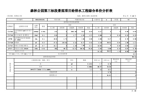
森林公园第三标段景观项目给排水工程综合单价分析表
0.96
0
0.18
0.18
0.13
10-63
室外塑料给水管(粘接连 接) DN110
10m
0.1
86.4
15.21
0
16.42
12.1
8.64
1.52
0
1.64
1.21
借1-105 回填砂
m3
0.3
27.2
130.02
2.12
5.17
3.81
8.16
39.01
0.64
1.55
1.14
借1-104 回填土夯填基(槽)坑
m3
0.7
22.4
0
1.19
4.26
3.14
15.68
0
0.83
2.98
2.2
10-378 管道压力试验 DN200
100m
0.01
430.4
88.23
16.23
81.78
60.26
27.2
130.02
2.12
5.17
3.81
8.16
39.01
0.64
1.55
1.14
借1-104 回填土夯填基(槽)坑
m3
0.7
22.4
0
1.19
4.26
3.14
15.68
0
0.83
2.98
2.2
10-377 管道压力试验 DN100
100m
0.01
352
65.7
12.84
66.88
49.28
3.52
计量单位
m
工程量
3988
定额编号
定额项目名称
城市公园服务水平评价【范本模板】
分类号TU密级U D C编号10486武汉大学硕士学位论文城市公园服务水平评价-—以武汉市为例错误!:曾桂林学号: 2009202090071指导教师姓名、职称: 詹庆明教授肖映辉副教授学科、专业名称,:城市规划与设计错误!:城市信息系统二〇一一年九月The service level evaluation of urban parks —-a case study in WuhanSeptember。
2011郑重声明本人的学位论文是在导师指导下独立撰写并完成的,学位论文没有剽窃、抄袭、造假等违反道德、学术规范和侵权行为,本人愿意承担由此而产生的法律后果和法律责任,特此郑重声明。
学位论文作者:曾桂林摘要城市公园绿地是城市重要的绿色基础设施,公园绿地的主要功能有生态服务、休闲娱乐服务和防灾避难服务。
随着社会经济的发展,城市生活环境质量越来越受到人们关注。
公园绿地对居民的服务水平是衡量一个城市生活质量、人与自然和谐关系的一个重要参考.本文以武汉市三环以内的城市建成区为主要研究区域,以武汉市公园绿地为研究对象,以GIS为主要技术手段,对武汉市现状和规划公园绿地服务水平进行比较研究,探讨影响武汉市公园绿地服务水平的主要因素,对武汉市公园绿地规划建设和管理提出建议。
论文主要分为以下四个部分:第一部分:介绍论文研究背景、目的和意义,并对核心概念进行界定。
回顾国内外有关公园绿地研究的文献,阐述研究相关理论与方法。
还对研究区概况和数据收集情况进行说明。
第二部分:在文献阅读、归纳的基础上,结合城市规划理论、可达性理论等学科的理论方法,构建基于GIS的可达性评价框架和服务效率评价指标,对公园绿地进行等级划分和服务半径确定,详细阐述可达性评价参数和步骤、服务效率评价指标.第三部分:按照构建的分析方法框架,对武汉市进行实证研究。
首先,运用缓冲区分析法、行进成本法、网络分析法对武汉市公园绿地可达性进行评价并对评价结果进行比较。
盘龙区工程施工价格(3篇)
第1篇随着我国城市化进程的加快,建筑行业得到了快速发展。
昆明市盘龙区作为昆明市的核心城区,工程建设项目日益增多。
本文将对盘龙区工程施工价格进行分析,以期为相关企业和个人提供参考。
一、工程类型与价格1. 民用建筑盘龙区民用建筑主要包括住宅、商业、办公楼等。
根据建筑规模、结构形式、装饰标准等因素,价格差异较大。
一般而言,多层住宅施工价格为每平方米1000-1500元,高层住宅施工价格为每平方米1500-2000元。
商业、办公楼等公共建筑施工价格较高,约为每平方米2000-3000元。
2. 公共设施盘龙区公共设施包括道路、桥梁、公园、学校、医院等。
其中,道路、桥梁施工价格相对较高,每平方米约为1000-2000元。
公园、学校、医院等公共设施施工价格约为每平方米800-1500元。
3. 基础设施盘龙区基础设施包括供水、供电、供气、通信等。
施工价格受工程规模、地质条件等因素影响,每平方米约为500-1000元。
二、影响工程价格的因素1. 地质条件地质条件是影响工程施工价格的重要因素。
在地质条件复杂、地下水位高的地区,施工难度较大,成本相应增加。
2. 施工材料施工材料价格波动较大,直接影响工程总成本。
如钢筋、水泥、砂石等主要材料价格上涨,会导致工程价格上升。
3. 设计方案设计方案对施工价格影响较大。
设计方案合理、施工工艺先进,可以降低施工成本。
4. 施工周期施工周期越长,人力、物力、财力投入越多,施工价格越高。
5. 施工环境施工环境包括天气、地形、交通等因素。
恶劣的施工环境会增加施工难度和成本。
三、工程价格控制措施1. 优化设计方案,提高施工工艺水平,降低施工成本。
2. 严格材料采购管理,确保材料质量,降低材料成本。
3. 加强施工进度管理,缩短施工周期,降低施工成本。
4. 合理安排施工计划,充分利用资源,提高施工效率。
5. 加强施工安全管理,减少安全事故,降低安全事故损失。
总之,盘龙区工程施工价格受多种因素影响,相关企业和个人在工程建设项目中应充分考虑这些因素,合理控制工程成本。
管廊计费方案
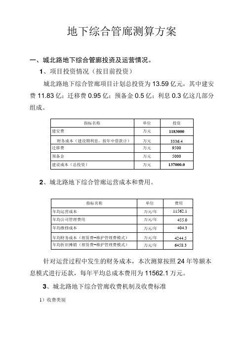
地下综合管廊测算方案一、城北路地下综合管廊投资及运营情况。
1、项目投资情况(按目前投资)城北路地下综合管廊项目计划总投资为13.59亿元,其中建安费11.83亿;迁移费0.95亿;预备金0.5亿;利息0.3亿这几部分组成。
2、城北路地下综合管廊运营成本和费用。
针对运营过程中发生的财务成本,本次测算按照24年等额本息模式进行还款,每年平均总成本费用为11562.1万元。
3、城北路地下综合管廊收费机制及收费标准1)收费类别在物价部门指导下,管廊公司与各入廊管线单位协商确定两类收费:①入廊费或租赁费,②维护管理费。
入廊费为一次性收取的使用费,租赁费为24年分期收取(特许经营期为25年,其中:建设期1年,运营期24年)的使用费。
2)定价机制1入廊费或租赁费根据建设成本按“空间比例法”测算,维护管理费根据日常维护的相关费用按“空间比例法”分摊。
维护管理费为地下综合管廊日常维护发生的相关费用。
2入廊费或租赁费根据建设成本按“空间比例法之工作区域”测算,维护管理费根据日常维护的相关费用按“空间比例法之工作区域”分摊。
维护管理费为地下综合管廊日常维护发生的相关费用。
3.入廊费或租赁费“年限使用比例法”测算,维护管理费根据日常维护的相关费用按“空间比例法之工作区域”分摊。
维护管理费为地下综合管廊日常维护发生的相关费用。
3)以城北路管廊为例的收费标准1.“空间比例法”1、入廊费入廊费单价=计算基数义空间占比♦孔数♦长度。
入廊费总计二入廊费单价义孔数又长度。
计算基数为13.6亿元(总投资)。
如:电力管线空间占比32%,孔数约65孔,长度11.5公里,经测算(13.6亿元又32%;65孔;11.5公里=582.2元/孔•米),入廊费单价约582.2元/孔•米。
电力管线入廊费总计=582.2元/孔•米义65孔X11.5公里=43519万元。
具体管线单位入廊费计算如下表:表12、租赁费年租赁费单价=计算基数义利率又(1+利率)分期付款期数-T〔(1+利率)分期付款期数一1〕义空间占比♦孔数♦长度。
《城规划设计计费指导意见》2018年修订稿

《城市规划设计计费指导意见》修订课题组第三次工作会议会议资料2017年7月14日中国城市规划协会·重庆目录第一部分修编工作说明. (4)一、工作背景. (4)二、修编原则与思路. (4)三、修编依据. (5)四、主要内容. (6)五、工作过程. (8)第二部分《城乡规划设计计费指导意见》说明. (10)第三部分《城乡规划设计计费指导意见》正文. (11)1 城市总体规划. (11)1.1 总体规划 (11)1.2 城镇群规划 (13)1.3 城乡统筹规划 (13)1.4 多规合一 (13)2 分区规划. (14)3 详细规划. (15)3.1 控制性详细规划 (15)3.2 修建性详细规划 (16)4 风景区规划. (19)4.1 风景区规划大纲 (19)4.2 风景区总体规划 (19)4.3 风景区控制性详细规划 (20)4.4 风景区修建性详细规划 (21)5 城市近期建设规划. (21)6 城镇体系规划. (23)7 城市设计. (24)7.1 总体城市设计 (24)7.2 重点地区城市设计 (25)7.3 专项城市设计 (26)7.4 其它 (27)8 镇规划. (27)8.1 镇总体规划 (27)8.2 镇详细规划 (28)9 乡、村规划. (28)9.1 乡规划 (28)9.2 村庄规划 (29)1.5 村庄整治设计 (29)10 交通规划. (30)3.3 综合交通规划 (30)3.4 交通详细规划 (32)3.5 交通详细设计 (33)3.6 轨道交通规划 (35)3.7 交通专项规划 (42)3.8 交通改善规划 (44)3.9 交通影响评价 (44)3.10 交通量化分析 (45)11 市政基础设施规划. (46)4.5 市政基础设施专项规划 (46)4.6 市政基础设施建设专项规划 (47)4.7 综合管线规划 (48)4.8 海绵城市建设专项规划 (48)12 单独编制历史文化名城(名镇、名村)保护规划及文化遗产保护专项规划 (49)7.5 历史文化名城保护规划 (49)7.6 历史文化名镇保护规划 (50)7.7 历史文化名村保护规划 (51)7.8 文化遗产保护专项规划 (52)7.9 历史文化街区和历史地段保护整治规划 (54)13 其他类专项规划. (55)8.3 公共服务类专项规划 (55)8.4 城市综合防灾专项规划 (57)8.5 城市地下空间专项规划 (59)8.6 生态环境景观类专项规划 (59)8.7 更新改造类专项规划 (60)14 规划选址与规划设计条件. (61)9.3 规划选址、选线. (61)9.4 规划设计条件. (64)15 信息技术服务. (66)15.1 信息咨询服务 (66)15.2 信息加工处理 (67)15.3 信息系统开发. (67)15.4 智慧“城市规划” (69)16 研究型规划. (69)16.1 研究型规划—总体层面 (69)16.2 研究型规划—实施层面 (70)16.3 研究型规划—工程层面 (71)17 规划咨询. (72)17.1 顾问咨询服务 (72)17.2 开发策划 (73)18 编制标书. (74)19 规划标底. (75)第一部分修编工作说明一、工作背景2001年国家计委《关于放开和下放部分商品和服务价格的通知》(计价格[2001]1218号)中取消了1993年由建设部、国家物价局联合颁布的《城市规划设计收费标准》,放开了规划设计市场。
昆明市人民政府令第145号——昆明市城市地下空间开发利用管理规定
昆明市人民政府令第145号——昆明市城市地下空间开发利用管理规定文章属性•【制定机关】昆明市人民政府•【公布日期】2018.10.24•【字号】昆明市人民政府令第145号•【施行日期】2019.01.01•【效力等级】地方政府规章•【时效性】现行有效•【主题分类】城市建设正文昆明市城市地下空间开发利用管理规定第一章总则第一条为了加强地下空间开发利用管理,促进土地的节约集约利用,保障有关权利人合法权益,根据《中华人民共和国城乡规划法》《中华人民共和国土地管理法》等法律规定,结合本市实际,制定本规定。
第二条本规定适用于昆明市城市总体规划确定的城市规划区范围内地下空间的开发利用管理。
法律、法规对国防、人民防空、文物保护、矿产资源等方面的地下空间开发利用管理已有规定的,从其规定。
第三条地下空间实行分层开发利用,坚持竖向分层立体综合开发和横向有关空间连通开发,优先用于防空防灾设施、基础设施和公共服务设施的建设。
第四条各县(市)区人民政府和开发(度假)园区管委会应当加强对地下空间开发利用管理工作的领导,建立工作协调机制,将地下空间普查及修(补)测、规划编制、信息管理等经费纳入财政预算。
第五条城乡规划行政管理部门负责地下空间开发利用的规划和信息管理工作。
国土资源行政管理部门负责地下空间开发利用的用地和不动产登记管理工作。
住房城乡建设行政管理部门负责地下空间工程建设和建(构)筑物交易、物业管理的监督管理。
人民防空管理部门负责地下空间开发利用涉及人民防空事项的有关管理工作。
其他有关行政管理部门应当按照各自职责,做好地下空间开发利用的有关管理工作。
第六条鼓励社会资本投资开发建设和运营管理地下空间。
第二章规划管理第七条地下空间规划分为地下空间开发利用专项规划和控制性详细规划。
地下空间规划应当根据地下空间现状资料进行编制,符合国民经济和社会发展规划、城市总体规划、土地利用总体规划,并与人民防空规划、地下交通规划、地下管线规划、海绵城市建设规划等专业规划相衔接。
地下空间利用论证报告

合能“天河路”项目地下空间及空中连廊规划论证报告成都西南交通大学设计研究院有限公司二〇一四年七月目录1总则.............................................................................................................................................1.1 项目背景.............................................................................................................1.2论证依据..............................................................................................................1.3主要论证内容.....................................................................................................1.4论证结论.............................................................................................................. 2拟建项目简介...........................................................................................................................2.1拟建地块用地现状............................................................................................2.2规划设计条件通知书 .......................................................................................2.3拟建项目设计方案............................................................................................2.4项目空中连廊简介............................................................................................2.5项目地下空间利用方案................................................................................... 3区域现状分析...........................................................................................................................3.1区域土地利用现状............................................................................................3.3区域市政管网现状............................................................................................4 区域规划分析..........................................................................................................................4.1区域土地利用规划............................................................................................4.2区域道路网络规划............................................................................................ 5项目必要性论证 ......................................................................................................................5.1成都市地下空间利用背景 ..............................................................................5.2 市政道路地下商业开发案例研究 ...............................................................5.3打造一体化商业综合空间的需要.................................................................5.4提高城市地下空间利用效率的需要............................................................5.5满足地面交通分流的需要 ..............................................................................5.6提高城市综合人防工事水平的需要............................................................ 6项目可行性论证 ......................................................................................................................6.1空中连廊可行性论证 .......................................................................................6.1.1连廊净空可行性论证 ....................................................................................6.1.2连廊的通行能力影响论证 ...........................................................................6.2地下空间相关管理规定...................................................................................6.3交通影响论证.....................................................................................................6.5消防疏散安全性论证 .......................................................................................6.6无障碍设计可行性论证...................................................................................7 地下空间开发控制 ................................................................................................................7.1 1#与2#号地块.............................................................................................7.2 2#与3#号地块.............................................................................................7.3 地铁连接通道.................................................................................................. 8结论及建议 ...............................................................................................................................8.1结论 .......................................................................................................................8.2管理要求与建议 ................................................................................................ 附件:附件1 郫县规划管理局市政工程规划条件附件2郫县规划管理局规划条件通知书附件3 地下空间出让面积统计1总则1.1 项目背景图1-1 项目地理位置示意图合能”天河路”项目地处成都市郫县犀浦镇西区花园片区,西面临银河西路(天河路),南面临城市主干道围城路,东面临银河东路(天辰路),北面临国道317线(成灌路)。
- 1、下载文档前请自行甄别文档内容的完整性,平台不提供额外的编辑、内容补充、找答案等附加服务。
- 2、"仅部分预览"的文档,不可在线预览部分如存在完整性等问题,可反馈申请退款(可完整预览的文档不适用该条件!)。
- 3、如文档侵犯您的权益,请联系客服反馈,我们会尽快为您处理(人工客服工作时间:9:00-18:30)。
盘龙城国家考古遗址公园及博物馆配套地下空间工程概算对比表
单位:万元 序号 一 1 1.1 1.2 1.3 1.4 1.5 1.6 1.7 1.8 1.9 二 2.2 2.20 2.1 2.3 2.4 2.5 2.6 2.7 2.8 2.9 2.10 2.11 2.12 2.13 2.14 2.15 2.16 2.17 2.18 2.19 3 3.1 费用项目名称 建安工程费 建筑工程费 基坑支护工程 结构工程 装饰工程 龙造型结构 龙造型装饰 土方工程 桩基检测费 室内给排水系统 气体灭火及控制系统工程 设备安装工程 室内变配电及电力照明 充电桩设备及安装费 消防系统 智能照明控制系统 智能应急照明系统 消防电源监控系统 漏电火灾监控系统 火灾自动报警系统 电话综合布线系统 有线电视系统 视频监控系统 防火门监控系统 安保无线对讲系统 门禁控制系统 公共广播及背景音乐系统 离线式电子巡更系统 车位引导及车库出入口管理系统 通风空调系统 直梯 扶梯 室外工程 室外绿化景观工程 建议园 林绿化 单位 建议弱 电单位 (车位 智能 化) 建议暖 通单位 建议电 梯单位 建议弱 电单位 建议消 防单位 (深化 设计) 建议强 电单位 (特种 建议总 包单位 承包单 中南院 人防院 中南院费用列 无设计 位 图纸 图纸 支 备注 人防院费 用列支 备注
盘龙城国家考古遗ห้องสมุดไป่ตู้公园及博物馆配套地下空间工程概算对比表
单位:万元 序号 3.2 3.3 3.4 3.5 费用项目名称 室外道路及广场 室外给排水及构筑物 室外电力照明工程 室外覆土工程 承包单 中南院 人防院 中南院费用列 无设计 位 图纸 图纸 支 建议园 林绿化 单位 备注 人防院费 用列支 备注