sagui安装说明
Legrand AV LW65 70 75Ux 安装说明说明书
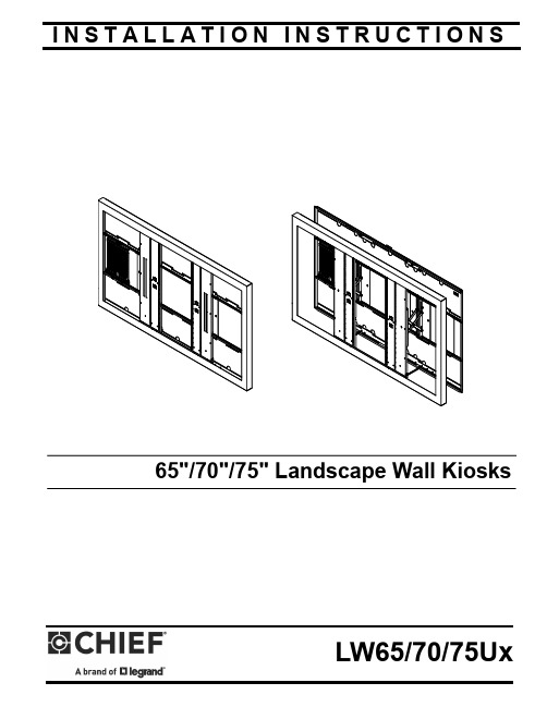
I N S T A L L A T I O N I N S T R U C T I O N S65"/70"/75" Landscape Wall KiosksLW65/70/75UxLW65/70/75Ux Installation InstructionsDISCLAIMERLegrand | AV and its affiliated corporations and subsidiaries (collectively “Legrand | AV”), intend to make this manualaccurate and complete. However, Legrand | AV makes no claim that the information contained herein covers all details,conditions or variations, nor does it provide for every possible contingency in connection with the installation or use of this product. The information contained in this document is subject to change without notice or obligation of any kind. Legrand | AV makes no representation of warranty, expressed or implied, regarding the information contained herein. Legrand | AV assumes no responsibility for accuracy, completeness or sufficiency of the information contained in this document.Chief® is a registered trademark of Legrand AV Inc.DEFINITIONSMOUNTING SYSTEM: A MOUNTING SYSTEM is theprimary Chief product to which an accessory and/or component is attached.ACCESSORY: AN ACCESSORY is the secondary Chiefproduct which is attached to a primary Chief product, and may have a component attached or setting on it.COMPONENT: A COMPONENT is an audiovisual itemdesigned to be attached or resting on an accessory or mounting system such as a video camera, CPU, screen, display, projector, etc.WARNING: A WARNING alerts you to the possibility ofserious injury or death if you do not follow the instructions.CAUTION: A CAUTION alerts you to the possibility ofdamage or destruction of equipment if you do not follow the corresponding instructions.IMPORTANT SAFETY INSTRUCTIONSWARNING: Failure to read, thoroughly understand, andfollow all instructions can result in serious personal injury, damage to equipment, or voiding of factory warranty! It is the installer’s responsibility to make sure all mounting systems are properly assembled and installed using the instructions provided.WARNING: Failure to provide adequate structural strengthfor this mounting system can result in serious personal injury or damage to equipment! It is the installer’s responsibility to make sure the structure to which this mounting system is attached can support five times the combined weight of all equipment. Reinforce the structure as required before installing the mounting system.WARNING: Exceeding the weight capacity can result inserious personal injury or damage to equipment! It is the installer’s responsibility to make sure the weight of components attached to swing door does not exceed:•LW65/70/75UB Models : 175 lbs (79.4 kg)•LW65/70/75UW Models : 175 lbs (79.4 kg)Removable storage panel capacity: 5 lbs (2.3 kg)The extended position is for installation and service only.WARNING: Use this mounting system only for its intendeduse as described in these instructions. Do not use attachments not recommended by the manufacturer.WARNING: Never operate this mounting system if it isdamaged. Return the mounting system to a service center for examination and repair.WARNING: Do not use this mounting system outdoors.IMPORTANT ! : The LW65/70/75UB and LW65/70/75UWlandscape wall kiosks are designed to be mounted to:• a bare 8" concrete or 8"x8"x16" concrete block wall; or • a 2" x 4" wood studs (16" on center maximum) wall with a maximum drywall thickness of 5/8"; or•a steel stud (16" on center maximum) wall with a maximum drywall thickness of 5/8"NOTE: The kiosks have an adjustable depth of 3" to 5".NOTE: Available monitor space reduced by 0.25" (6.25mm) forkiosks with glass installed.--SAVE THESE INSTRUCTIONS--Installation Instructions LW65/70/75Ux TABLE OF CONTENTSLW65/70/75Ux Installation Instructions DIMENSIONSDIMENSIONS...continuedLEGENDDestornillador Phillips Kreuzschlitzschraubendreher Chave de fendas Phillips Cacciavite a stella Kruiskopschroevendraaier Tournevis à pointe cruciformeLlave de bocaGabelschlüsselChave de bocasChiave a punte aperte SteeksleutelClé à fourche PerforarBohrlochFazer furoPraticare un foroGat borenPercez un trouLlave de cabeza hexagonal SechskantschlüsselChave de cabeça sextavada Chiave esagonale ZeskantsleutelClé à tête hexagonaleTOOLS REQUIRED FOR INSTALLATIONslots on lower side of the rear frame panel opening.The panel will snap into the slots, securing it to therear frame.Locate Mounting SiteWARNING: IMPROPER INSTALLATION CAN LEAD TO MOUNT FALLING CAUSING SEVERE PERSONAL INJURY OR DAMAGE TO EQUIPMENT! It is the installers responsibilityto make certain the structure to which the mount is being attached is capable of supporting five times the combined weight of all components attached to cover:•LW65/70/75Ux Models: 175 lbs (79.4 kg)Removable storage panel capacity: 5 lbs (2.3 kg).(See Figure 2)IMPORTANT ! : When installing the rear frame it is preferable to use all possible available attachment points.•The rear frame must be installed to a MINIMUM of two studs, one located between the scissorsmechanism, and one to the next stud on either theleft or right. (See Figure 3) and (See Figure 4). 1.Determine the horizontal center of the rear frame, andwhere it should be located on the wall.•For wood or steel stud walls, use a level and mark the uppermost locations over studs for attachment aminimum of 16" apart and a maximum of 24" apart.(See Figure 3) and (See Figure 4)•For concrete walls, use a level and mark the eight locations for attachment in two columns, a columnwithin 4 inches of each side of the scissors area. (SeeFigure 5)Figure 52.Drill one pilot hole (see Table 1 for size) at top locationsmarked in Step 1 (See Figure 3), (See Figure 4) and (See Figure 5) and follow fastener information (appropriate for wall type) located in T able 1.IMPORTANT ! : Refer to Fastener Installation Methods (located in Appendix at end of Installation Instructions)for details on installing product into various wall types. IMPORTANT ! : Attaching the rear frame requires a minimum of 8 wall fasteners.IMPORTANT ! : (OPTIONAL for wood and steel stud installations) For additional rigidity in the installation, use a Snap-Toggle (AC), 1/4-20 x 1-3/4" Phillips screw (AD) and 1/4" washer (AE) at each corner of the rear frame if it is not attached to the studs at those points. (See Figure 7)Figure 63.Partially install fasteners into wall, but do not completelytighten to wall.4.Hang rear frame, aligning upper mounting slot clearanceholes over fasteners and adjust side-to-side for properlocation. (See Figure 6)5.Tighten fasteners to secure rear frame to wall at uppermounting slots.6.Drill six remaining pilot holes (see Table 1 for size) atattachment locations and follow fastener information(appropriate for wall type) located in Table 1. (See Figure 6) 7.Tighten six fasteners to secure rear frame to wall at middleand lower mounting slots.Installation Instructions LW65/70/75Ux IMPORTANT ! : (OPTIONAL for wood and steel studinstallations) For additional rigidity in the installation, use a Snap-Toggle (AC), 1/4-20 x 1-3/4" Phillips screw (AD) and 1/4" washer (AE) at each corner of the rear frame if it is not attached to the studs at those points. (See Figure 7)IMPORTANT ! : Refer to Fastener Installation Methods (located in Appendix at end of Installation Instructions) for details on installing snap toggles and related fasteners into various wall types.3.Clean the inside edge of the outer cover (approximately oneinch depth around entire opening) with an alcohol wipe or something similar, and let dry. (See Figure 9)4.Install gasket strip (B) around inside edge of outer coveropening. (See Figure 9)NOTE: Do not install gasket strip right up to edge. The gasket strip should be placed approximately 1/16" away fromopening.Carefully lay flat panel face down into the depth-adjustable(B)Leave approximately1/16" space betweenedge of openingand gasket strip5LW65/70/75Ux Installation InstructionsWARNING: IMPROPER INSTALLATION CAN LEAD TO DISPLAY FALLING CAUSING SERIOUS PERSONAL INJURY OR DAMAGE TO EQUIPMENT! Using screws ofimproper size may damage your display. Properly sized screws will easily and completely thread into display mounting holes. If spacers are required, be sure to use longer screws of the same diameter.7.Select screw diameter by examining hardware (BA-BL) andcomparing with mounting holes on flat panel.8.Select spacers:•Spacers are NOT required if mounting holes are not recessed and carrier frame can lay flat against flatpanel.•Spacers (BM, BN) ARE required if mounting holes are recessed, or if protrusions prevent carrier frame fromlaying flat.•Spacers may also be used between the carrier frame and flat panel to create more space for AVcomponents, or to accommodate thinner flat panels.(See Depth Adjustment section for furtherinformation.)9.Select screw length:•By hand, insert SHORTEST length screw of selected diameter (BA, BD, BG, or BJ) through universal washer(BO--if required), carrier frame, spacer (BM, BN--ifrequired), into flat panel mounting hole. Do NOT threadscrew into hole at this time.IMPORTANT ! : The M8 screws do NOT require a washer. Use the universal washer (BO) ONLY with the M4, M5 or M6 screws.•Proper screw length requires base of screw head to protrude above flat washer a distance equal to orgreater than the screw diameter. If screw length isinadequate, select longer screw. Select shortest screwwhich will protrude the required distance.10.Place carrier frame onto back of flat panel and match theVESA pattern on flat panel to the carrier frame mountingslots. Also match the threaded studs in outer frame to the hooks on the carrier frame. (See Figure 11)e selected screws (BA-BL), washers (BO--if required),and spacers (BM, BN--if required), to connect carrier frame to back of flat panel. (See Figure 11)NOTE: The outer cover depth may be adjusted between 3" - 5" to make room for a variety of different flat panelthicknesses. (See Figure 12)•This outer cover adjustable depth can also be used to make more space between the back of the flat paneland wall for AV component storage.•The 4 Phillips screws removed in Step 1 can be replaced with four 10-24 x 3-1/2" Phillips screws (CC)for larger depth adjustments.Figure 1212.Tighten thumb nuts over threaded studs in four locations onthe hinged frame. (See Figure 12)13.Replace and fasten four Phillips screws which wereremoved in Step 1, OR replace the removed screws with four 10-24 x 3-1/2" Phillips head screws (CC) to allow for a larger depth adjustment of the outer frame. (See Figure 12) 12and outsidepanelrear frame, ensuring that studs on carrier frame line up with holes on scissors assembly. (See Figure 14)Figure 1419.Push in outer cover until latched into rear frame.20.Add one 10-24 x 3/8" button head security screw (CB) in holeon top, AND two security screws in two holes on bottom to lock door. (See Figure 15)Figure 15Cabling1.Cables may be placed in the rear frame areas outside ofthe scissors assembly (gray) areas. (See Figure 16) IMPORTANT ! : Do NOT place cables where they may move between the scissors assembly. Damage to cables may occur. (See Figure 16)Figure 16LW65/70/75Ux Installation InstructionsAPPENDIXFastener Installation MethodsIMPORTANT ! : See Table 1 for appropriate hardware and pilot hole sizes for various wall types.Steel StudIMPORTANT ! : See Site Requirements for Wood or Steel Stud section before proceeding with Steel Studs installation to ensure installation site meetsrequirements! The drywall must have a minimum5.Line up anchor with attachment point.Figure 23If back side of wall is unfinished, to a minimum of one stud left*Steel stud type and structural strength must conform to the North American Specification for thedrywall must be installedand right of the stud(s) being used to install the mount. Drywall must be secured to studs with screws a maximum of 12" (305mm) apart down center of stud.1/2" minimumSteel Studs ONLYLW65/70/75Ux Installation InstructionsUSA/InternationalA 6436 City West Parkway, Eden Prairie, MN 55344P 800.582.6480 / 952.225.6000F 877.894.6918 / 952.894.6918Europe A Franklinstraat 14, 6003 DK Weert, NetherlandsP +31 (0) 495 580 852F +31 (0) 495 580 845Asia Pacific AOffice No. 918 on 9/F, Shatin Galleria18-24 Shan Mei StreetFotan, Shatin, Hong KongP 852 2145 4099 F 852 2145 44778800-003318 Rev00 2021 Legrand | AV 08/2021LW65/70/75Ux Installation Instructions。
MuxLab 3G-SDI ST2110 over IP 无压缩网关转换器快速安装指南说明书
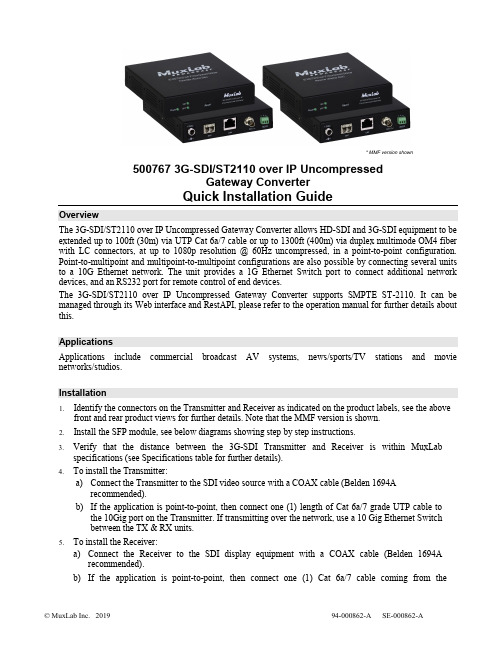
* MMF version shown500767 3G-SDI/ST2110 over IP UncompressedGateway ConverterQuick Installation GuideOverviewThe 3G-SDI/ST2110 over IP Uncompressed Gateway Converter allows HD-SDI and 3G-SDI equipment to be extended up to 100ft (30m) via UTP Cat 6a/7 cable or up to 1300ft (400m) via duplex multimode OM4 fiber with LC connectors, at up to 1080p resolution @ 60Hz uncompressed, in a point-to-point configuration. Point-to-multipoint and multipoint-to-multipoint configurations are also possible by connecting several units to a 10G Ethernet network. The unit provides a 1G Ethernet Switch port to connect additional network devices, and an RS232 port for remote control of end devices.The 3G-SDI/ST2110 over IP Uncompressed Gateway Converter supports SMPTE ST-2110. It can be managed through its Web interface and RestAPI, please refer to the operation manual for further details about this.ApplicationsApplications include commercial broadcast AV systems, news/sports/TV stations and movie networks/studios.Installation1.Identify the connectors on the Transmitter and Receiver as indicated on the product labels, see the abovefront and rear product views for further details. Note that the MMF version is shown.2.Install the SFP module, see below diagrams showing step by step instructions.3.Verify that the distance between the 3G-SDI Transmitter and Receiver is within MuxLabspecifications (see Specifications table for further details).4.To install the Transmitter:a)Connect the Transmitter to the SDI video source with a COAX cable (Belden 1694Arecommended).b)If the application is point-to-point, then connect one (1) length of Cat 6a/7 grade UTP cable tothe 10Gig port on the Transmitter. If transmitting over the network, use a 10 Gig Ethernet Switchbetween the TX & RX units.5.To install the Receiver:a)Connect the Receiver to the SDI display equipment with a COAX cable (Belden 1694Arecommended).b)If the application is point-to-point, then connect one (1) Cat 6a/7 cable coming from theTransmitter, to the 10Gig port on the Receiver. If transmitting over the network, use a 10Gig Ethernet Switch between the TX & RX units.6.If the configuration is a point-to-multipoint or multipoint-to-multipoint:a)You will need to use an Ethernet Switch with Gigabit ports and DHCP Server support. In additionIGMP Protocol support is required for the multipoint-to-multipoint case. Verify that the Ethernet Switch is configured correctly and that the DHCP Server is enabled and that the IGMP Protocol is enabled for multipoint-to-multipoint applications.b)Connect all Transmitters and Receivers to the Ethernet Switch.7.Connect the 12 VDC power supply to each Receiver and to an AC power outlet. Next connect eachTransmitter in the same manner. If power is present, the green power LED on each Transmitter and Receiver will illuminate.Note: Power ‘ON’ the 3G-SDI / ST2110 over IP uncompressed gateway converter only after all data connections have been made.8.Power ‘ON’ the 3G-SDI equipment and verify the image quality.9.The 500767 provides a 1GB Ethernet port to connect additional network devices (e.g. RestAPI controlsoftware).10.This product supports RS232 for remote control on end devices.11.The following diagram illustrates a typical point-to-multipoint LAN configuration.TroubleshootingThe following table describes some of the symptoms, probable causes and possible solutions in regard to the installation of the 3G-SDI/ST2110 over IP Uncompressed Gateway:If you still cannot diagnose the problem, please call MuxLab Customer Technical Support at 877-689-5228 (toll-free in North America) or (+1) 514-905-0588 (International).SFP Module Installation2321 Cohen Street, Montreal, Quebec, Canada. H4R 2N7Tel: (514) 905-0588 Fax: (514) 905-0589 Toll Free (North America): (877) 689-5228E-mail:******************:。
广发自由行俯仰椅子安装说明书
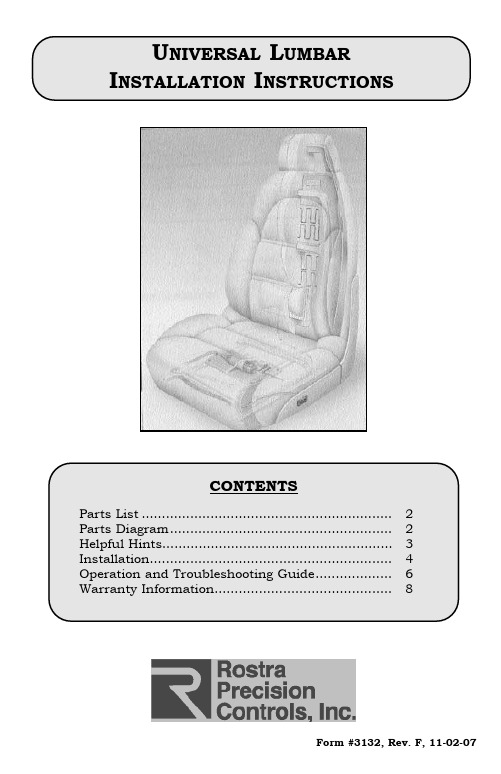
Form #3132, Rev. F, 11-02-07P AGE 212in. (30.5cm)10.25in. (26.0cm)Standard Bladder Assy(250-1453 KIT)Switch AssyPump/Pouch AssyFront Bladder Assy(250-1454 KIT)Fused HarnessMain HarnessPump/Pouch ConnectorF AF IGURE BP AGE: Remove screws from bottom edge of12in(30.5cm)standard/extendedbladder10in(26.5cm)small bladderfront bladderF2cable tiesF IGURE 4SWITCH INSTALLATIONSWITCH INSTALLATION:F IGURES5 &61.Choose a switch location on a flatsurface on the console or the seat sidepanel.2.Remove center console or side seatpanel as needed.3.Cut a 1/2” x 1-3/8” hole in the consoleor the seat side panel using ROSTRAtool (250-1428) or using T EMPLATE A ONPAGE6.4.Place the bezel from hardware packageonto switch.5.Insert switch through opening and snapin place.seat panel switchcenter console switchP AGE5F6F IGURE5OPERATION:The switch is used to operate the system. If your lumbar system was installed correctly, it should perform as indicated below.INFLATE/DEFLATE:To inflate the bladder, depress the high side of switch. The pump motor will continue pumping air until bladder maximum is reached, then overflow will vent out through the pump system.To deflate bladder, depress the low side of the switch, and with your body weight pres-sure, the bladder will vent out the air as long as you hold the switch.P AGE6WIRING D IAGRAMR = Red = PowerY = Yellow = ValveB = Black = GroundGR = Green = PumpRE-CONNECT NEGATIVE BATTERY CABLE.。
安装说明
一. gauss主程序安装:1.在“gauss安装\GAUSS_7.0_Win_32”目录下安装运行setup.exe 文件注:把gauss 主程序安装在“c:\ gauss7.0”目录下即可。
2.Copy “gauss安装\crack”目录下的三个文件gauss.exe、tgauss.exe、gauss7_tbe.lic 到“c:\ gauss7.0”目录下,覆盖掉原有同名文件。
3.Copy “gauss安装\crack”目录下的文件gauss7_tbe.lic 到“c:\ gauss7.0\ flexlm”目录下。
至此三步,gauss主程序安装完毕,此时可运行gauss.exe ,实现gauss程序的基本功能。
二. datatool (gauss数据处理程序)程序安装:1.在“gauss安装\datatool\GDT_7.0_Win_32”目录下安装运行setup.exe 文件注:把datatool主程序安装在“c:\ gdt7.0”目录下即可。
2.Copy “gauss安装\datatool”目录下的三个文件gdtw.exe、gdt.exe、gauss7_tbe.lic 到“C:\gdt7.0”目录下,覆盖掉原有同名文件。
3.Copy “gauss安装\datatool”目录下的文件gauss7_tbe.lic 到“c:\ gdt7.0\ flexlm”目录下。
至此三步,gauss辅助数据处理程序安装完毕,此时可运行gdtw.exe ,实现gauss程序的数据导入功能。
主要功能:把excel的.xls 文档转成gauss 程序可用的.txt 文档格式。
三.GPE2(gauss配套的极值计算软件包)程序安装:1.在“gauss安装\ ”目录下安装运行GPE2-70.exe 文件注:把GPE目录安装在“c:\ gauss7.0”目录里面即可。
2.Copy “gauss安装\”目录下的两个文件gpe2.gcg、gpe2.fst到“C:\gauss7.0”目录下,覆盖掉原有同名文件。
Sun StorEdge 3000 系列 FRU 安装指南说明书
Sun StorEdge™ 3000 系列FRU 安装指南Sun StorEdge 3310 SCSI 阵列Sun StorEdge 3510 FC 阵列Sun Microsystems, Inc.4150 Network CircleSanta Clara, CA 95054 U.S.A.650-960-1300部件号 817-2767-112003 年 6 月,修订版 A有关本文档的建议,请发送至:/hwdocs/feedback版权所有 © 2003 Dot Hill Systems Corporation, 6305 El Camino Real, Carlsbad, California 92009, USA.保留所有权利。
Sun Microsystems, Inc. 和 Dot Hill Systems Corporation 可能拥有与本产品或文档中涉及的技术相关的知识产权。
具体来说(且不仅限于此),这些知识产权包括 /patents 所列出的美国专利中的一项或多项,以及在美国或其他国家(地区)申请的一项或多项补充专利或未决专利。
本产品或文档按照限制其使用、复制、分发和反编译的许可证进行分发。
未经 Sun 及其许可方(如果有)的事先书面授权,不得以任何形式或任何手段复制本产品或文档的任何部分。
第三方软件由 Sun 供应商提供版权及许可授权。
本产品的某些部分来源于 Berkeley BSD 系统,已获得 University of California 的许可。
UNIX 是在美国和其他国家(地区)的注册商标,已通过 X/Open Company, Ltd. 获得独家许可。
Sun、Sun Microsystems、Sun 标志、Sun StorEdge、AnswerBook2、, 和 Solaris 是 Sun Microsystems, Inc. 在美国和其他国家(地区)的商标或注册商标。
ArcGIS Desktop 9.3 安装指南

ArcGIS Desktop 9.3 安装指南介绍 (4)产品介质包中的内容 (4)关于ArcGIS Desktop的安装程序 (7)Windows Installer技术 (7)问题,反馈和信息 (8)技术帮助 (8)ArcGIS知识库 (8)在互联网上访问ESRI主页 (8)ESRI教育解决方案 (8)最低系统要求 (9)Python要求 (12)卸载Python (14)获取license文件 (15)卸载ArcGIS产品 (17)现有的ArcGIS Desktop用户 (19)使用ArcGIS 9.0, 9.1和9.2版本的用户 (19)ArcGIS 8.x的用户 (19)如果拥有一个较早的ArcView (3.x)版本 (20)关于license manager (21)安装license manager (22)License manager要求 (22)如何安装license manager (22)安装概览 (25)1. 指定license manager的位置 (25)2.安装license manager (25)3.启动ArcGIS Desktop的安装程序 (25)在计算机上安装ArcGIS Desktop (27)如何准备安装ArcGIS Desktop (27)如何安装ArcGIS Desktop (27)Python的安装位置 (31)ArcGIS Desktop的安装位置 (33)其他的安装组件 (33)在网络服务器上安装ArcGIS Desktop (34)如何在网络服务器上安装ArcGIS Desktop (34)从网络服务器上安装ArcGIS Desktop (36)静默安装ArcGIS Desktop (37)静默安装ArcGIS Desktop (37)要求 (37)ArcGIS Desktop安装命令行参数 (37)如何进行典型的ArcGIS Desktop静默安装 (38)如何进行完全的的ArcGIS Desktop静默安装 (39)如何进行自定义的ArcGIS Desktop静默安装 (39)如何静默卸载ArcGIS Desktop (41)在已经安装了ArcView或ArcEditor (单机版)的情况下切换到ArcGIS Desktop (43)添加可选的安装组件 (44)如何添加或删除ArcGIS Desktop安装组件 (44)安装Tutorial Data (46)安装ArcGIS Desktop Developer Kit Resources (47)ArcGIS Desktop Administrator (48)安装了ArcGIS Desktop的Desktop Administrator (48)使用Desktop Administrator注册单机版产品 (51)卸载ArcGIS Desktop (53)卸载ArcGIS Desktop产品 (53)在Vista上卸载ArcGIS Desktop (53)卸载Python (54)如何静默卸载ArcGIS Desktop (54)安装ArcGIS Desktop Developer Resources (58)ArcGIS Desktop安装过程中的疑难解答 (59)介 绍ArcGIS Desktop可以作为ArcView, ArcEditor,或ArcInfo三种产品来使用。
操作说明(1)

视觉系统软件安装说明1、必须安装的软件GenICamSetup.88:改程序用于设置相机;iDiscoverGenie:修改相机的IP地址;工控机上用于连接PLC的网口ip地址必须设置为:192.168.250.7;连接相机的网口IP地址不能在250网段,可以设置为:192.168.0.1;此软件不需要安装。
Sherlock7220ReleaseX86:sherlock安装包;Visual.Studio.2010.简体中文旗舰版:上位机运行环境;Sentinel_7.5.0:软件授权驱动。
2、软件安装a、GenICamSetup.88安装双击上图绿色.exe文件,进行安装。
点击“Next”,继续安装点击“Next”,继续安装点击“Next”,继续安装点击“Install”,继续安装点击“Finish”,安装完成。
b、sherlock软件安装双击上图绿色.exe文件,进行安装。
点击“Next”,继续安装点击“I Agree”,继续安装点击“Next”,继续安装点击“Next”,继续安装点击“Install”,继续安装点击“Close”,完成安装。
c、Visual.Studio.2010.简体中文旗舰版安装双击上图绿色.exe文件,进行安装。
点击上面绿色处进行安装,跳转到下面页面:单击“下一步”,继续安装选择“我已阅读并接受许可条款”,点击“下一步”继续安装选择“完全”,点击“安装”。
在安装的过程中会提示重新启动计算机。
b、软件授权驱动安装:点击绿色.exe安装驱动点击“Next”继续安装如图设置,点击“Next”继续安装如图设置,点击“Next”继续安装点击“Install”继续安装选择“Yes”继续安装点击“Finish”完成安装。
到这里所有软件已经安装完成,下面需要对软件进行一些初始化设置:在改路径里面必须包含以上文件件:DALSA CCD是检测程序文件件;camerafile是相机配置文件夹;image里面是最近100张NG图片;1里面保存的是每次的偏移量。
牛牛安装包界面控件使用说明
牛牛安装包界面控件使用说明本说明文档旨在对nsNiuniuSkin.dll控件的使用进行说明,指导调用者顺利的将牛捉安装包界面控件控件集成进安装包中,使第三方产品也能拥有完美的安装包的UI体验功能。
官方网址:/牛牛安装包界面控件是一个可集成于NSIS的插件,采用Duilib开发,在使用时,安装包制作者只需要做如下两件事情:1. 通过配置Duilib的资源,设计好界面显示的元素2. 在NSIS的脚本中,通过NSIS脚本调用nsNiuniuSkin.dll的相关接口,集成UI及安装包的业务功能在控件的资源中,采用的是通过TAB控件来实现不同阶段的安装界面,比如:选择路径、许可协议、安装进度、完成、卸载等,在实际使用中,通过NSIS脚本来设置当前需要显示的TAB页,即可完美的呈现出需要的界面UI了。
在我们的示例中,提供了两份安装的界面如下:注意,最新版本的控件已经将可用的NSIS及7z的相关文件包含在示例包中,可以通过一键打包批处理脚本进行打包了,具体如下:1). 将要打包的文件复制到FilesToInstall目录下,可以包含文件及若干层的目录2). 修改相关项目下的skin目录下的资源文件及xml脚本来配置UI3). 添加相关(或者在我原来的示例上修改,这样更快)的NSIS脚本文件,并与UI相匹配4). 指定好相关的ICO、licence等信息5). 执行build.bat脚本,一键打包,build脚本会做三件事:将FilesToInstall 目录下的文件打包成app.7z;将skin目录下的文件打包成skin.zip;调用nsis 编译程序,编译nsi文件,输出安装包。
以上描述的build脚本为全自动执行,可以轻松集成进您现有的软件发布流程中,实现自动化打包发布。
牛牛安装包界面控件包含的接口较多,以下逐一进行介绍[以下接口调用及参数说明按在NSIS脚本中的调用示例来说明]:1.接口初始化接口InitSkinPage此接口函数用于初始化nsNiuniuSkin.dll控件的配置信息.调用示例:nsNiuniuSkin::InitSkinPage "$PLUGINSDIR\" "${INSTALL_LICENCE_FILENAME}"参数说明:2.重新设置许可协议的文件名nsNiuniuSkin::ResetLicenseFile $hInstallDlg "newlicensename.rtf"设置后,许可协议显示控件将会重新加载许可协议文件,这个比较适合用于多语言版本的不同许可协议加载显示。
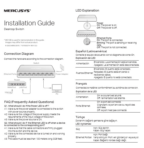
梅赛思MS108桌面交换机快速安装指南说明书
© 2023 MERCUSYS 7107500274 REV1.0.2Installation GuideDesktop Switch* MS108 is used for demonstration in this guide. Images may differ from actual product.Connection DiagramConnect the hardware according to the connection diagram.FAQ (Frequently Asked Questions)A1: Make sure that the cable connectors are firmly pluggedinto the switch and the device.A2: Make sure the connected device is turned on and workingproperly.A3: The cable must be less than 100 meters long (328 feet).Q2. What should I do if the Ethernet LED is off when a device is connected to the corresponding port?A1: Make sure the power adapter is connected to the switchwith power source properly.A2: Make sure the voltage of the power supply meets therequirements of the input voltage of the switch. A3: Make sure the power source is ON.Q1. What should I do if the Power LED is off ?The power is on. The power is off.The port is connected.The port is sending or receiving The port is not connected.Explicación del LEDAlimentaciónEncendido: La alimentación está encendida.Apagado: La alimentación está desconectada.Puertos EthernetEncendido: El puerto está conectado.Parpadeo: El puerto está enviando orecibiendo datos.Apagado: El puerto no está conectado.Español (Latinoamérica)Conecte el equipo de acuerdo con el diagrama de conexión.FrançaisExplication de la LED Connectez le matériel conformément au schéma de connexion.Alimentation On: le courant est allumé.Off: l'alimentation est éteinte.Ports EthernetOn: le port est connecté.Clignotant: le port envoie ou reçoit des données.Off: le port n'est pas connecté.TürkçeLED AçıklamasıDonanımı bağlantı şemasına göre bağlayın.GüçAçık: Güç açıktır.Kapalı: Güç kapalı.Ethernet PortlarıAçık: Port bağlı.Yanıp sönüyor: Port veri gönderiyor veya alıyor.Kapalı: Bağlantı noktası bağlı değil.PortuguêsExplicações sobre LEDsConecte o hardware de acordo com o diagrama de conexão. EnergiaAceso: O dispositivo está ligado.Apagado: O dispositivo está desligado.Portas EthernetAceso: A porta está conectada.Piscando: A porta está enviando ou recebendo dados.Apagado: A porta não está conectada.Safety Information· Keep the device away from water, fire, humidity or hot environments.· Do not attempt to disassemble, repair, or modify the device, If you need service, please contact us.· Do not use damaged charger or USB cable to charge the device.· Do not use any other chargers than those recommended.· Place the device with its bottom surface downward.· Adapter shall be installed near the equipment and shall be easily accessible.· Operating T emperature: 0˚C ~ 40˚CPlease read and follow the above safety information when operating the device. Wecannot guarantee that no accidents or damage will occur due to improper use of device. Please use this product with care and operate at your own risk.Explanation of the Symbols on the Product LabelThis product bears the selective sorting symbol for Waste electrical and electronic equipment (WEEE). This means that this product must be handled pursuant to European directive 2012/19/EU in order to be recycled or dismantled to minimize its impact on the environment.User has the choice to give his product to a competent recycling organization or to the retailer when he buys a new electrical or electronic equipment..For technical support, the user guide and more information, please visit /en/support .This is a class B product. In a domestic environment, this product may cause radio interference, in which case the user may be required to take adequate measures.CE Mark Warningвимогам нормативних документів та вимогам, що передбачені чинними законодавчими актами України.Para informações de aspectos de segurança e adequação do produto no território brasileiro consulte: -.br/anatel/pt-br/UK Declaration of ConformityMercusys hereby declares that the device is in compliance with the essential requirements and other relevant provisions of the Electromagnetic Compatibility Regulations 2016 and Electrical Equipment (Safety) Regulations 2016.The original UK declaration of conformity may be found at https:///support/ukca/EU Declaration of ConformityMERCUSYS hereby declares that the device is in compliance with the essential requirements and other relevant provisions of directives 2014/30/EU, 2014/35/EU, 2009/125/EC , 2011/65/EU, and (EU) 2015/863. The original EU declaration of conformity may be found at /en/ce.BSMI Notice安全諮詢及注意事項請使用原裝電源供應器或只能按照本產品注明的電源類型使用本產品。
GPS软件安装说明
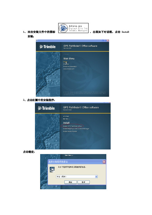
1、双击安装文件中的图标,出现如下对话框,点击Install
安装;
2、点击红圈中的安装程序:
点击确定:
安装中:
3、点击下一步:
直到出现下面的图框,选择红圈中的选项:点击前进;
4、输入安装码:key(安装序列号)
不用更新,选择跳过这一步,点击完成即可;
5、点击桌面的的图标出现英文版的,如下图:
点击中文汉化包,出现;
双击,出现如下图:直到下面的黑色的对话框消失即汉化完成;
在点击桌面的图标,即安装完成:
6、安装完成后点击菜单中的“功能”选项出现:选择“其他”下面的“坐标系统管理器”:
点击“坐标系统”
制
复制到刚才打开的坐标系统中,点击保存即可;
关闭PFO 软件,再打开,在选项
式了;。
集成平台安装配置手册

达观集成平台安装配置手册达观集成平台安装配置手册 (1)一、软件安装 (2)1. 软件安装顺序 (2)2. 软件安装操作 (3)2.1 加密狗驱动安装 (3)2.2 配置向导安装 (5)2.3 联动安装 (11)2.4 录像服务安装 (14)2.5 备份工具安装 (15)2.6 集成环境安装 (16)二、软件配置 (17)1.软件特性 (17)2.软件功能介绍 (18)3. 软件配置 (19)3.1 服务安装 (19)3.2添加报警设备 (25)3.3 视频模块的添加 (28)3.4门禁设备的添加 (29)3.5 地图添加管理 (33)3.6 资源权限管理 (38)三、软件使用及运维 (45)1.软件打开顺序 (45)2.软件各模块功能说明 (46)2.1 联动功能介绍 (46)2.2 数据库工具功能介绍 (49)2.3 录像服务功能介绍 (51)2.4集成环境功能介绍 (56)3.集成平台日常运维 (57)四、常见错误说明 (58)1. Service 启动失败 (58)2. 设备显示脱机 (58)3. 报警时无联动图像 (58)一、软件安装1. 软件安装顺序2. 软件安装操作2.1 加密狗驱动安装˙打开安装光盘中的HASPUserSetup.exe 加密狗安装程序图一图二图三图四图五2.2 配置向导安装打开光盘中的配置与服务.msi 安装文件启动配置向导,在第一步选项卡里选择导入证书,证书导入完成后选择下一步。
在新选项卡中正确填写数据库连接参数并点击测试连接,测试连接成功后点击下一步选择初始化数据库按钮,初始化完成后点击下一步选择安装服务,安装成功后选择启动服务,然后下一步即可请按照下面提示填写参数,参数填写完成后点击创建站点,站点创建完成后点击完成即可。
(站点地址为:http://localhost:10000)2.3 联动安装双击光盘中的视频录像服务安装包点击下一步在新对话框中选择安装目录点击下一步直到安装完成双击备份工具安装在弹出的对话框中点击下一步选择安装路径点击下一步直至安装完成2.6 集成环境安装双击集成安装程序,在弹出的画面中点击下一步开始安装选择安装路径点击下一步,直至安装完成1.2继电器及通信服务安装(根据实际情况安装)安装方法与以上模块相同二、软件配置1.软件特性●兼容与扩展开放式模块化程序设计,使集成平台可以迅速友好地接入并管理各类已知及未来未知的安防子系统。
商海导航《简明安装及操作手册》

商海导航中小型商业管理系统简明操作手册海信网络科技股份有限公司2002-08目录1 系统安装步骤 (1)1.1系统安装前的准备工作 (1)1.1.1 工作站安装准备 (1)1.1.2 打印机安装 (1)1.1.3 收款机安装准备 (2)1.1.4 SQL版商海导航其他安装准备 (3)1.2系统安装 (3)1.2.1 工作站系统安装步骤 (4)1.2.2 收款机系统安装 (10)1.3商海导航安装注意事项 (12)2 系统投入运行 (13)2.1运行前数据准备工作 (13)2.2系统投入运行 (24)3 日常业务处理 (27)4 系统注册 (27)5系统中常见问题的处理 (29)5.1前台收款机无法连网,处于单机状态。
(29)5.2数据库连接不成功。
(29)5.3报表或单据无法正确打印。
(30)5.4系统后台结帐时,提示加密系统异常,无法结帐。
(30)5.5商海导航系统数据库异常 (30)5.6系统安装后无法正常运行,提示系统内部错误。
(30)5.7后台各种销售报表帐对不起来。
(30)5.8系统运行一段时间后,想启动会员管理功能,如何进行? (30)5.9W INDOWS NT4.0及MS SQL S ERVER7.0/2000的安装步骤是什么? (31)5.10SQL版商海导航系统工作站提示无法连接数据库。
(31)5.11如何关闭退出会员服务程序的运行 (32)1 系统安装步骤1.1 系统安装前的准备工作在安装商海导航中小型商业管理系统(简称:商海导航)之前,要做好以下准备工作。
1.1.1 工作站安装准备(1)在各工作站上安装中文Win98(建议用Win98第二版),为各计算机分配一个名称,如:PC01、PC02、…等。
(2)配置各工作站网卡、网络用户以及网络协议等,使系统中各台计算机可以互相访问。
建议网络用户使用Windows 登录或Microsoft友好登录。
图1-1-1 设置网络登录方式图1-1-2 设置计算机名称(3)设置各工作站显示器屏幕分辩率为800x600,颜色为增强色(16位)或真彩色(24位)。
GHOST软件使用说明(图解)
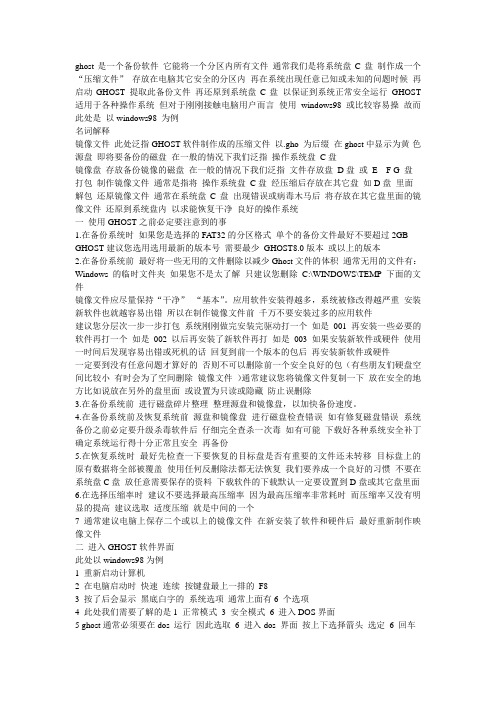
ghost是一个备份软件它能将一个分区内所有文件通常我们是将系统盘C盘制作成一个“压缩文件”存放在电脑其它安全的分区内再在系统出现任意已知或未知的问题时候再启动GHOST 提取此备份文件再还原到系统盘C盘以保证到系统正常安全运行GHOST 适用于各种操作系统但对于刚刚接触电脑用户而言使用windows98或比较容易操故而此处是以windows98 为例名词解释镜像文件此处泛指GHOST软件制作成的压缩文件以.gho 为后缀在ghost中显示为黄-色源盘即将要备份的磁盘在一般的情况下我们泛指操作系统盘C盘镜像盘存放备份镜像的磁盘在一般的情况下我们泛指文件存放盘D盘或E F G 盘打包制作镜像文件通常是指将操作系统盘C盘经压缩后存放在其它盘如D盘里面解包还原镜像文件通常在系统盘C盘出现错误或病毒木马后将存放在其它盘里面的镜像文件还原到系统盘内以求能恢复干净良好的操作系统一使用GHOST之前必定要注意到的事1.在备份系统时如果您是选择的FAT32的分区格式单个的备份文件最好不要超过2GB GHOST建议您选用选用最新的版本号需要最少GHOST8.0版本或以上的版本2.在备份系统前最好将一些无用的文件删除以减少Ghost文件的体积通常无用的文件有:Windows的临时文件夹如果您不是太了解只建议您删除C:\WINDOWS\TEMP 下面的文件镜像文件应尽量保持“干净”“基本”。
应用软件安装得越多,系统被修改得越严重安装新软件也就越容易出错所以在制作镜像文件前千万不要安装过多的应用软件建议您分层次一步一步打包系统刚刚做完安装完驱动打一个如是001 再安装一些必要的软件再打一个如是002 以后再安装了新软件再打如是003 如果安装新软件或硬件使用一时间后发现容易出错或死机的话回复到前一个版本的包后再安装新软件或硬件一定要到没有任意问题才算好的否则不可以删除前一个安全良好的包(有些朋友们硬盘空间比较小有时会为了空间删除镜像文件)通常建议您将镜像文件复制一下放在安全的地方比如说放在另外的盘里面或设置为只读或隐藏防止误删除3.在备份系统前进行磁盘碎片整理整理源盘和镜像盘,以加快备份速度。
NETGEAR GS752TXS Smart Switch 安装指南说明书
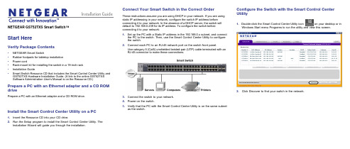
NETGEAR GS752TXS Smart Switch™Start HereVerify Package Contents• NETGEAR Smart Switch• Rubber footpads for tabletop installation• Power cord• Rack-mount kit for installing the switch in a 19-inch rack• Installation Guide• Smart Switch Resource CD that includes the Smart Control Center Utility and GS752TXS Hardware Installation Guide. (A link to the online GS752TXSSoftware Administration User's Manual is on the Resource CD.)Prepare a PC with an Ethernet adapter and a CD ROM drivePrepare a PC with an Ethernet adapter and a CD ROM drive.Install the Smart Control Center Utility on a PC1. Insert the Resource CD into your CD drive.2. Run the Setup program to install the Smart Control Center Utility. TheInstallation Wizard will guide you through the installation.Connect Your Smart Switch in the Correct OrderThese instructions assume you are using DHCP in your network. If you are usingstatic IP addressing in your network, configure the switch IP address beforeconnecting it to your network. In the absence of a DHCP server, the switch willdefault to 192.168.0.239 for its IP address. To configure the switch beforeconnecting it to your network:1. Set up the PC with a Static IP address in the 192.168.0.x subnet, and connectthe PC to the switch. Then, use the Smart Control Center Utility to configurethe switch.2. Connect each PC to an RJ-45 network port on the switch front panel.Use category 5 (Cat5) unshielded twisted-pair (UTP) cable terminated with anRJ-45 connector to make these connections.3. Connect the switch to your network.4. Power on the switch.5. Verify that the PC with the Smart Control Center Utility is on the same subnetas the switch.Configure the Switch with the Smart Control CenterUtility1. Double-click the Smart Control Center Utility icon on your desktop or inWindows Start menu Programs to run the utility and view this screen.2.Click Discover to find your switch in the network.May 2011This symbol was placed in accordance with the European Union Directive 2002/96 on the Waste Electrical and Electronic Equipment (the WEEE Directive). If disposed of within the European Union, this product should be treated and recycled in accordance with the laws of your jurisdiction implementing the WEEE Directive.NETGEAR, the NETGEAR logo, and Connect with Innovation are trademarks and/or registered trademarks of NETGEAR, Inc. and/or its subsidiaries in the United States and/or other countries. Information is subject to change without notice. Other brand and product names are registered trademarks or trademarks of theirrespective holders. © 2011 NETGEAR, Inc. All rights reserved.The Smart Control Center Utility finds the switch and displays its MAC Address, IP Address, and model number. If you cannot configure your switch, verify that the cable connections are secure, that the IP address configuration of the PC is in the same subnet as the switch, and click the Discover button.3. Click to select the line displaying the details of your switch. If there are multipleswitches in your network, be sure to select the one you want to configure.4. Click Web Browser Access to view the switch log in screen.5. Enter the default password of password in lower case letters and click Login.The switch will display the switch settings main page. Configure the switch for your network. Consult the Reference Manual on the Resource CD or the onlinehelp in the switch for assistance with configuration procedures.After you log in to the switch, the main Web Browser Access menu displays.Use the configuration menu options to configure your switch.Troubleshooting TipsHere are some tips for correcting simple problems you may have.• Be sure to power on your PC and switch in the correct sequence.Follow this sequence. Turn off the switch and computer. First, turn on the switch and wait two minutes. Next, turn on the computer.• Make sure the Ethernet cables are securely plugged in.For each powered on computer connected to the switch with a securely plugged in Ethernet cable, the corresponding switch LAN port status light will be lit. • Make sure the network settings of the computer are correct.In most cases, computers should be configured to obtain an IP address via DHCP. For help with this, refer to the Reference Manual; a link to the onlineReference Manual is on the Resource CD.If your network uses static IP addresses, be sure the switch and computer are configured with valid IP addresses.Technical SupportThank you for selecting NETGEAR products.After installing your device, locate the serial number on the label of your product and use it to register your product at /register. Registration is required before you can use the telephone support service. Registration via our website is strongly recommended.Go to for product updates, documentation, and support . For additional information about setting up, configuring, and using your GS752TXS, see the User Manual .For complete DoC please visit the NETGEAR EU Declarations of Conformity website at: /app/answers/detail/a_id/11621/For GNU General Public License (GPL) related information, please visit /app/answers/detail/a_id/2649WARNING!!DO NOT stack equipment, or place equipment in tight spaces, or in drawers. Be sure your equipment is surrounded by at least 2” of air space.。
Isomag 4 Security Key Cover安装指南说明书
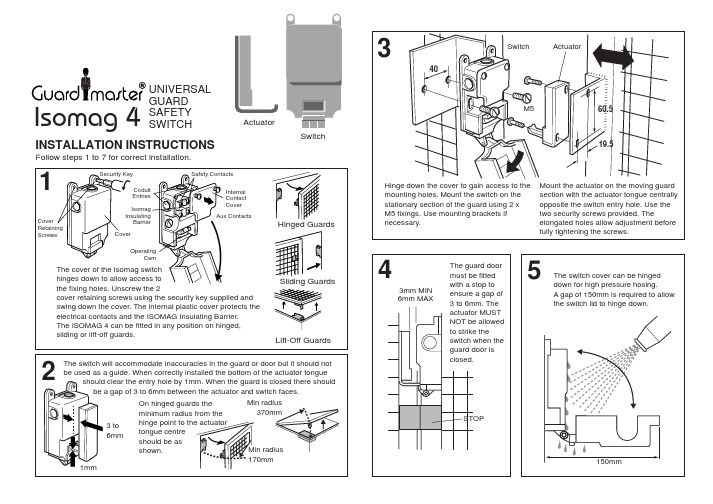
Isomag Insulating
Barrier
Cover
Safety Contacts
Internal Contact Cover Aux Contacts
Hinged Guards
Operating Cam
The cover of the Isomag switch hinges down to allow access to the fixing holes. Unscrew the 2 cover retaining screws using the security key supplied and swing down the cover. The internal plastic cover protects the electrical contacts and the ISOMAG Insulating Barrier. The ISOMAG 4 can be fitted in any position on hinged, sliding or lift-off guards.
40
Switch
ActuatorM560.5Fra bibliotek19.5
Hinge down the cover to gain access to the mounting holes. Mount the switch on the stationary section of the guard using 2 x M5 fixings. Use mounting brackets if necessary.
convenient of the 3 knock out conduit entry
points.
光交箱安全管理系统安装说明书V1.4【呕心沥血整理版】

光交箱安全管理系统安装说明书一、系统要求操作系统:Windows XP SP3(。
Net 4.0 full要求SP3以上)以上需要有Administrator用户权限Windows 7及Windows Server 2003也需要Administrator 用户权限安装。
本安装说明主要针对Windows XP 用户.如果Windows 7以后可能会安装失败。
需要联系客服人员。
已测试操作系统:Windows Server 2008(在具有多核处理器的计算机,您可能无法安装SQL Server 2005,需要安装SQL Server 2008,或如果数据库安装到别处,请联系3M技术支持工程师)Windows 7 可用运行安装数据库脚本时需要修改文件夹权限。
Windows XP SP3可用。
注意:由于本系统为一系统服务程序,因此对于Windows XP用户要求需要一台安装干净,完整的Windows XP系统.任何其他精减版或Ghost版的XP都可能会安装失败。
硬件要求:●CPU:主频2。
0G以上●内存:2G以上●硬盘:600M以上剩余空间数据库:目前只支持SQL Server 2005 Express,如果需要支持其他版本的数据库,目前Windows Server 2008 standard 对Sql Server 2005 支持不好,需要安装Sql Server2008,需要3M技术人员支持.二、短信猫安装检查配件和软硬件需求无误后,按以下步骤安装短信猫设备1、SIM卡槽弹卡按钮用小螺丝刀或其它工具按下自弹式SIM卡座的黄色小按钮,将短信猫各模块的SIM卡槽取出(如图1—4)图1图2图3 图4 2、安装SIM卡设备需求:已开通短信业务的SIM 卡一张,短信猫一个安装过程如下(图3—4):图5 图63、设备安装到计算机将已经安装好SIM卡的短信猫用RS232或USB数据线的一端连接到短信猫口上,另一端连接到计算机的串口接口或者USB接口上(注RS232的短信猫需要接上电源)。
30曲库维护软件安装及说明
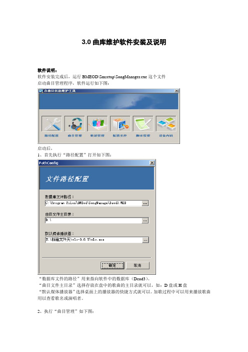
3.0曲库维护软件安装及说明软件说明:软件安装完成后,运行BMEOD\Smsetup\SongManager.exe这个文件启动曲目管理程序,软件运行如下图:启动后,1、首先执行“路径配置”打开如下图:“数据库文件的路径”用来指向软件中的数据库(Deod3)。
“曲目文件主目录”选择存放在盘中的歌曲的主目录就可以,如:D盘或H盘“默认煤体播放器”选择桌面上的播放器的快捷方式就可以。
加歌过程中可以用来播放歌曲用以查看歌名或演唱者。
2、执行“曲目管理”如下图:○1添加曲目:“添加以编号命名的曲目”:用来添加改好编号的文件信息。
“添加时创建曲目编号”:可以任意输入起始编号,如:660000,往里添加文件信息时,程序会自动顺序写入编号,并可以自动把歌曲文件复制到相应的文件夹内。
接着进行信息的编辑歌曲或演者等,如下图:点击“自动预影片”可以用程序调用的播放器进行歌曲播放,用来添入歌曲名或歌星名等。
点击“下一条”直接进入下一条信息的编辑。
完成后,可以保存继续并退出。
○2“删除曲目”:可以一次性选择删除一条歌曲信息或多条信息的记录和对应的曲目文件。
(鼠标右键有快捷方式)○3“修改信息”:可以选择单条或多条信息同时进行修改。
○4“清空曲库”:一次性清空曲库中所有歌曲的信息和记录。
注:用此功能时,请做好曲库的备份。
○5“导入曲库”:此功能只能导入ACCESS数据库中的song表的信息(注:导入song表的结构必须要和Deod 库中的song表的结构一样才可以。
○6“查询曲目”:根据查询字段、查找方式和查找数值找相应的记录。
“显示全部”是在查找到一条记录后,再想查找其他的记录,首先要显示全部信息后才可再次查询。
○7“显示全部”:用来显示库中的全部信息。
○8“曲目校验”:对库中的歌曲信息和曲目进行匹配校验。
完成后如下图:○9“歌星信息校验”:用来检验哪些歌曲没有歌星。
校验完成后如下图○10“预览影片”:注:没有加密的歌曲○11“生成曲库”:生成歌曲数据库文件○12“导入曲库”:此项只能导入Songlist.dat这个文件。
智能导播系统安装手册

智能导播系统安装手册V1.0目录1、安装准备 (3)1.1检查安装环境 (5)1.1.1 适用录播软件系统 (5)1.1.2 配套升级录播硬件 (5)1.1.2 导播主机配置 (6)1.2安装光盘内容 (6)1.3安装步骤 (7)2、酷睿软硬件升级 (7)2.1硬件连线 (7)2.2软件安装 (8)2.2.1软件升级 (8)2.2.2软件配置 (8)3、迅捷软硬件升级 (13)3.1硬件连线 (13)3.2软件安装 (14)3.2.1软件升级 (14)3.2.2软件配置 (14)4、智能导播系统软件安装配置 (16)4.1环境配置 (16)4.1.1加密狗安装 (16)4.1.2 Windows配置 (16)4.2软件配置 (17)4.2.1软件安装 (17)4.2.2软件配置 (17)1、系统说明1.1研发背景随着酷睿和迅捷两种录播系统的广泛应用,学校多媒体教室的增多以及数字化校园工作的推进,录播教室和多媒体教室以及其他教室的统一管理逐渐变成一个研发课题。
导播系统就是在这样的背景下进行研发的。
它的产生的主要目标主要包括以下几个方面:1、管理卓越电子的酷睿和迅捷系列录播产品。
2、推进数字校园的标准化;1.2 系统简介产品将具有以下特点:1、远程管理教室的开关电源;2、远程辅助录制。
可以辅助授课教师进行授课实况录制,比如控制录制的开始、暂停、停止,切换录制场景、推拉摄像机的镜头,调整摄像角度,调整摄像效果等。
3、远程监视、控制迅捷、酷睿教室。
在无人职守的情况下,可以监视、录制教室内的现场情况,也可以根据老师的要求调整监控摄像头的拍摄角度;4、远程授权用户使用设备。
如果授课教师忘记带授权卡,那么集控管理教师将可以通过远程授权来授权授课教师使用录播系统(限于迅捷型)。
1.3系统部署1.5功能简述1.远程开/关教室;2.远程接管教室、调整摄像头、控制录制、远程切换录制场景;3.远程进行监控,本地录制;4.远程授权1、安装准备1.1检查安装环境1.1.1 适用录播软件系统1.1.2 配套升级录播硬件1.1.2 导播主机配置1.2 安装光盘内容智能导播3.0系统配套安装光盘内容1.3 安装步骤●酷睿软硬件升级●迅捷软硬件升级●智能导播系统软件安装配置2、酷睿软硬件升级2.1硬件连线该连线图,仅仅是新增的部分设备的原理图,录播的连线图参见《录播安装手册》,区别是所有的摄像头原来接到编辑机上,现在改为接到AV分配器上,然后从AV分配器分接到编辑机和网络视频服务器。
- 1、下载文档前请自行甄别文档内容的完整性,平台不提供额外的编辑、内容补充、找答案等附加服务。
- 2、"仅部分预览"的文档,不可在线预览部分如存在完整性等问题,可反馈申请退款(可完整预览的文档不适用该条件!)。
- 3、如文档侵犯您的权益,请联系客服反馈,我们会尽快为您处理(人工客服工作时间:9:00-18:30)。
上海电气集团
电站ECC系统SAP GUI软件安装
操作指南
前提:
安装介质:GUI730
补丁:GUI730_7_
安装步骤:
1、进入安装目录 \SAP GUI 730\NW_7.0_Presentation_\PRES1\GUI\WINDOWS\WIN32
2、双机SapGuiSetup
点击下一步
如为ECC用户,仅需安装SAPGUI FRO WINDOW 7.30,点击下一步
如有BCS则必须勾选BUSINESS EXPLORER 组件
默认安装路径
启动安装
注意:安装前关闭其他程序,避免更新windows 相关组建时报错。
再安装补丁程序:
安装完毕后SAP GUI 默认配置修改
点击左上方按钮,出现下拉菜单“选项”,点击后出现配置对话框择安全设置,修改为已禁用;目的:将每次上传下载的确认对话框功能取消。
保持用户的使用感受。
选择本地服务配置文件,修改路径到D:\personal\My Documents\SAP
点击确定按钮,关闭SAP GUI;
可选择将标准的saplogon.ini 覆盖现有D盘下同名文件,完成配置。
