A0308BroadcastGoAsync
APM飞控源码分析

APM飞控系统介绍APM飞控系统是国外的一个开源飞控系统,能够支持固定翼,直升机,3轴,4轴,6轴飞行器。
在此我只介绍固定翼飞控系统。
飞控原理在APM飞控系统中,采用的是两级PID控制方式,第一级是导航级,第二级是控制级,导航级的计算集中在medium_loop( ) 和fastloop( )的update_current_flight_mode( )函数中,控制级集中在fastloop( )的stabilize( )函数中。
导航级PID控制就是要解决飞机如何以预定空速飞行在预定高度的问题,以及如何转弯飞往目标问题,通过算法给出飞机需要的俯仰角、油门和横滚角,然后交给控制级进行控制解算。
控制级的任务就是依据需要的俯仰角、油门、横滚角,结合飞机当前的姿态解算出合适的舵机控制量,使飞机保持预定的俯仰角,横滚角和方向角。
最后通过舵机控制级set_servos_4( )将控制量转换成具体的pwm信号量输出给舵机。
值得一提的是,油门的控制量是在导航级确定的。
控制级中不对油门控制量进行解算,而直接交给舵机控制级。
而对于方向舵的控制,导航级并不给出方向舵量的解算,而是由控制级直接解算方向舵控制量,然后再交给舵机控制级。
以下,我剔除了APM飞控系统的细枝末节,仅仅将飞控系统的重要语句展现,只浅显易懂地说明APM飞控系统的核心工作原理。
一,如何让飞机保持预定高度和空速飞行要想让飞机在预定高度飞行,飞控必须控制好飞机的升降舵和油门,因此,首先介绍固定翼升降舵和油门的控制,固定翼的升降舵和油门控制方式主要有两种:一种是高度控制油门,空速控制升降舵方式。
实际飞行存在四种情况,第一种情况是飞机飞行过程中,如果高度低于目标高度,飞控就会控制油门加大,从而导致空速加大,然后才导致拉升降舵,飞机爬升;第二种情况与第一种情况相反;第三种情况是飞机在目标高度,但是空速高于目标空速,这种情况飞控会直接拉升降舵,使飞机爬升,降低空速,但是,高度增加了,飞控又会减小油门,导致空速降低,空速低于目标空速后,飞控推升降舵,导致飞机降低高度。
FiiO BTA30 DAC Transmitter 用户手册说明书

FiiO BTA30 DAC Transmitter User GuideHome » Fiio » FiiO BTA30 DAC Transmitter User GuideModel: BTA30Hi-Res Bluetooth Receiver and TransmitterA. Power button G. Line outB. Power indicator light H. Optical outputC. Bluetooth state/Codec/Sampling rate indicator light I. Coaxial input/outputD. Pair/Pause button J. Optical inputE. Receiving/Transmitting/DAC mode switch K. External antenna portF. Volume knob L. Power/Data portFunctions and Operations InstructionsTurn on: Short press button A after connecting to a USB device.Turn off: When the device is on, hold button A for about 2s until indicator light B and C turn off.Play/Pause: In RX/TX mode, short press button D.Clear pairing: When the device is powering on and in RX/TX mode (not pairing state), hold button A+D at the same time for about 5s.Force to pair: When the device is powering on and in RX/TX mode, hold button D for about 3s until indicator light C flashes alternately in red and green.Reconnecting state: Indicator light C quickly flashes twice every 2 seconds in green.How to use the BTA30 with two Bluetooth devices simultaneouslyBluetooth receiving (RX): After a successful pairing with Device 1, hold the button D for around 3s to enter pairing mode again. Search for “BTA30” on Device 2 and pair it with the BTA30. On Device 1, select “BTA30” in the device list and reconnect. You could also restart the BTA30 after a successful pairing with Device 2 in order to use the BTA30 with two Bluetooth devices simultaneously.Bluetooth transmitting (TX): The connecting steps are similar to the RX connection. After successful pairings with the two receiving devices respectively, restart the BTA30 in order to use it with the two Bluetooth receiving devices simultaneously. Note: When working in LDAC and aptX LL Bluetooth codec in TX mode, the BTA30 cannot be connected to two Bluetooth devices simultaneously.Audio input/outputBluetooth receiving (RX): Bluetooth devices can search for “BTA30” and complete the connection through Bluetooth, outputting audios via the BTA30’s line, coaxial or optical port ;Note: Under this mode, the coaxial, optical, and line output can work at the same time.Bluetooth transmitting (TX): The BTA30 can be connected to Bluetooth receiving devices, such as the BTR5 and BTR3K. (Audios can be input to the BTA30 through its USB input, coaxial or optical port.)Note:1. Under the mode of USB in and Bluetooth out, the volume knob cannot work, and the LDAC codec is not supported.2. IF it is connected to a Bluetooth receiving device, double click the PAIR button to switch Bluetooth codecs of the BTA30.DAC: Connect the BTA30 to computers through the USB port, outputting audios via the BTA30’s line out, coaxial output or optical output; Or decoding audio signals input by the BTA30’s coaxial and optical port, and output audios through the line out port.Note:WEEE Directive & Product DisposalAt the end of its serviceable life, this product should not be handed as household or general waste. It should be handed over to the applicable collection point for the recycling of electrical and electronic equipment or returned to the supplier for disposal.FiiO User GuideBTA30, DAC TransmitterReferencesFiiO--Born for MusicFiiO Support--Born for MusicRelated Manuals1. FiiO Touchscreen Player User Guide2. FiiO Portable High Resolution Music Player User Guide3. FiiO X7 Portable High-Resolution Audio Player User Guide FiiO X7 Portable High-Resolution Audio Player User Guide Before First...4. fiiO Portable High-Fidelity Bluetooth5.0 Amplifier User Guide fiiO Portable High-Fidelity Bluetooth 5.0 Amplifier Buttons nad Portslabeled/Operation...5. Fiio M15 Complete User Manual Fiio M15 Complete User Manual Foreword: Thank you so much...6. ifi ZEN DAC Signature V2 User Guide Thank you for purchasing the DAC Signature V2 from the...。
PlayStation 无线耳机说明书
For more instructions about the use of this product (including the Headset Companion app), visit /helpme.ENPrecautionsBefore using this product, carefully read this manual and any manuals for compatible hardware. Retain instructions for future reference.SafetyˎObserve all warnings, precautions, and instructions.ˎCHOKING HAZARD - Small parts. Keep out of the reach of small children.Use and handlingˎStop using the wireless headset immediately if you begin to feel tired or if you experiencediscomfort or pain in your head while operating the wireless headset. If the condition persists, consult a doctor.ˎAvoid prolonged use of the wireless headset. Take a break at about 30-minute intervals. ˎPermanent hearing loss may occur if the headset is used at high volume. Set the volume to asafe level. Over time, increasingly loud audio may start to sound normal but can actually be damaging your hearing. If you experience ringing in your ears or muffled speech, stop listening and have your hearing checked. The louder the volume, the sooner your hearing could be affected. To protect your hearing:ˋLimit the amount of time you use the headset at high volume. ˋAvoid raising the volume to block out noisy surroundings.ˋLower the volume if you can’t hear people speaking near you.ˎIf you feel that the headset is irritating your skin, stop using it immediately. ˎDo not expose the headset to high temperatures, high humidity or direct sunlight. ˎDo not put heavy objects on the headset.ˎDo not allow liquid or small particles to get into the headset.ˎDo not throw or drop the headset, or subject it to strong physical shock.ˎDo not place any rubber or vinyl materials on the headset exterior for an extended period oftime.ˎUse a soft, dry cloth to clean the headset. Do not use solvents or other chemicals. Do not wipewith a chemically treated cleaning cloth.ˎDo not disassemble or insert anything into the headset because this may cause damage to theinternal components or cause injury to you.ˎObserve all signs and instructions that require an electrical device or radio product to beswitched off in designated areas, such as gas/refueling stations, hospitals, blasting areas, potentially explosive atmospheres or aircraft.ˎThe battery used in this device may present a risk of fire or chemical burn if mistreated. Do notdisassemble, heat above 60 °C / 140 °F, or incinerate.Wireless headsetHeadset: CUHYA-0080Wireless Adaptor: CUHYA-0081Instruction Manual Part names and functionsPower/audio mode switchSets the audio mode or turns off headset.Positions:OFF - turns off the headset 1 - Standard Mode2 - Bass Boost Mode (default)This mode can be replaced with audio modes from the Headset Companion app.Adjusts the volume of the headset.MUTE buttonˎPress to switch microphone MUTE on and off. ˎTo engage the sidetone feature, hold down the MUTE button until a beep is heard. Then cycle through the sidetone volume settings (high, medium, off) by holding the MUTE button.Sidetone is a feature that allows you to hear your own voice from the headset. The sidetone volume is adjusted here, and not on the PS4™ system or other devices. When MUTE is on, the sidetone feature is turned off.L markingWhen the included audio cable is connected to the headset for use with mobile devices, the wireless function is turned off.Wireless adaptorReset button Status indicatorˎOn PlayStation®Vita systems, you can listen to audio in standard stereo formatand use the voice chat feature.ˎOn other mobile devices, you can listen to audio in standard stereo format only.HintsˎWhen the included audio cable is connected to the headset, the VSS (Virtual Surround Sound) button and the SOUND/CHAT buttons cannot be used. ˎOutput volume varies depending on the portable device that is connected. Adjust volume accordingly.ˎYou can use the supplied audio cable to connect the headset to your mobile device to listen to audio content and talk on the phone. ˋ I f you are unable to hear audio content using the cable with your mobile device, turn off headset power. ˋ Y our device may only support use of a standard audio cable (not included) to listen to audio content using the headset. Note that standard audio cables do not support voice communication. ˋ T his product is not compatible with all mobile devices. Some features may not work on all mobile devices.Charging the headsetWhen remaining battery level is low, the status indicator flashes red and a beep is heard. Charge the battery by connecting the headset to a supported USB device such as a PC. While the battery is charging, the status indicator lights up red. The status indicator light turns off when the battery is fully charged.HintsˎYou can view the remaining battery charge on a PS4™ system. It is shown on the status display that appears when you change the headset settings.ˎYou might not be able to charge the battery if the USB device or the USB hub does not provide enough power for charging. Try connecting the headset to a different USB device or a different USB connector on the device.ˎCharging takes approximately 3.5 hours when starting with no battery charge left. ˎWhen the remaining battery charge is low, the headset beeps while it is connected and receiving an audio signal.ˎIt is recommended that you charge the battery in an environment with atemperature of 5 °C - 35 °C / 41 °F - 95 °F. Charging in other environments might not be as effective.ˎIf you do not plan to use the wireless headset for an extended period of time, it is recommended that you fully charge it at least once a year to help maintain battery functionality.Status indicator displayHeadset1 F or repair options, visit /helpme.2 I f you see the flashing error light, retry the steps to Restore Headset again. If you continue to see the error after the Restore attempt, then visit /support/wirelessstereoheadset.Wireless adaptorInitial setup1 Charge the headset by connecting it to a USB port with a USB cable.The headset may need up to 3.5 hours to charge fully.2 Insert the wireless adaptor into the USB port.3 Slide the power switch on the headset to position “1” or “2”.Using the headset with PlayStation ®4 systemsThis headset is compatible with PS4™ system software version 5.00 or later. More than one headset can be used with a PS4™ system.Always update your system software to the latest version.Status displayWhen first connecting to a PS4™ system or when changing the settings, thefollowing status information is displayed in the upper left corner of the screen:Stereo Headset Audio Extension is a system setting that controls the type of audio output to the wireless headset. It is available only when the wireless adaptor is inserted.Audio output selectionWith the wireless headset you can listen to audio from the PS4™ system—including music, videos, and games—in Virtual Surround Sound.ˋYou can listen to both game audio and chat audio simultaneously.Use the SOUND/CHAT buttons to adjust the relative volume of game audio versus chat audio.ˋYou can change the audio output to the headset so that you can hear only chat audio.To change the audio output select (Settings)(Devices)[AudioDevices] [Output to Headphones]. NOTE:O n a PS4™ system, the wireless headset defaults to “ON” [All Audio].Using the headset with a computerYou can use the headset with a PC (with Windows® or macOS) that has a USB port. Insert the wireless adaptor into a USB port on the computer you want to use and then turn on the headset.HintsˎThe headset might not work with some computers.ˎThe VSS (Virtual Surround Sound) button and SOUND/CHAT buttons can be used only when the headset is connected to a PS4™ system .Using your headset with PlayStation ®VRYou can use an audio cable to connect your headset to the stereo headphone jack of PlayStation ®VR. This will output all game audio processed by the PlayStation ®VR,including 3D audio if supported by the game title.NoteThis headset only supports stereo or 7.1 virtual surround sound. 3D audio is supported on this headset only when plugged into the PS VR, while playing a PS VR game that supports 3D audio.Using the headset with a portable deviceYou can use an audio cable to connect your headset to the headphone jack of compatible devices.Headset Companion appWith the Headset Companion app, you can select an additional audio mode for your headset. There are several modes to choose from, each optimized to enhance different audio characteristics. These modes are developed exclusively for use with PS4™ systems.To get one of these audio modes, download the Headset Companion app from PlayStation™Store and follow the on-screen instructions.Once this process is complete, you can experience your selected mode on your headset by sliding the power/audio mode switch to position “2”.Resetting the headsetIf the headset does not respond when you try to operate it, reset it by doing the following:1Connect the wireless adaptor to a PS4™ system or other powered USB port.2 Insert a small pin or similar object (not included) into the hole surrounding the reset button in the wireless adaptor, and push in for at least one second.3 On the headset, hold down the MUTE button and the VSS button.4 While still holding down the MUTE button and the VSS button, slide thepower/audio mode switch to position “1” or “2”.Rating labelThe rating label contains specific model, manufacture and compliance information. It is located under the right earpad.To remove the earpad and access the rating label:1 Use one hand to hold the headset in place.2 With your other hand, grip the earpad frame.3 P ull the earpad out.To replace the earpad, align the earpad with the inner frame. Push it back onto the frame until it clicks.End of life product recyclingThe wireless headset is made of plastics, metals, and a lithium-ion battery. Follow localregulations when disposing of the wireless headset. Sony products can be recycled for free in the United States and Canada by dropping the product off at a number of nationwide locations. For details, visit /SonyInfo/csr/SonyEnvironment/spotlight/.VSS (Virtual Surround Sound) buttonThe Virtual Surround Sound effect is on by default. Press and hold for more than one second to turn the VSS on or off.繁體中文使用前須知事項使用本產品前,請先詳細閱讀本說明書及對應裝置的說明書,並妥善保存,以備將來參考之用。
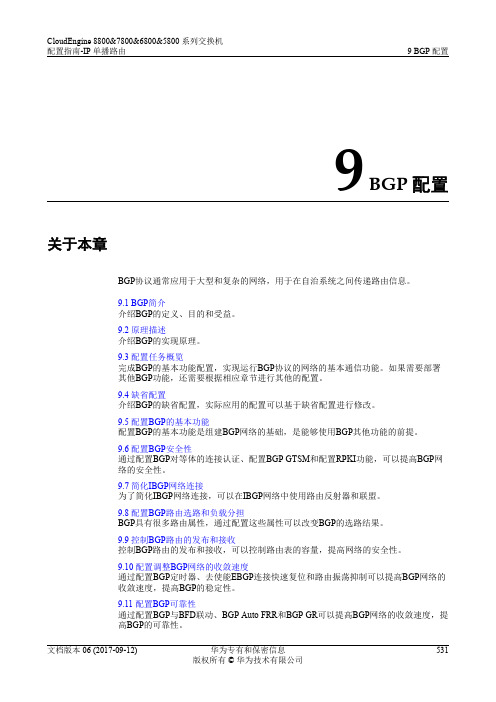
华为数据中心5800交换机01-09 BGP配置
说明
如果在AS内一台BGP设备收到EBGP邻居发送的路由后,需要通过另一台BGP设备将该路 由传输给其他AS,此时推荐使用IBGP。
9.3 配置任务概览 完成BGP的基本功能配置,实现运行BGP协议的网络的基本通信功能。如果需要部署 其他BGP功能,还需要根据相应章节进行其他的配置。
9.4 缺省配置 介绍BGP的缺省配置,实际应用的配置可以基于缺省配置进行修改。
9.5 配置BGP的基本功能 配置BGP的基本功能是组建BGP网络的基础,是能够使用BGP其他功能的前提。
9.6 配置BGP安全性 通过配置BGP对等体的连接认证、配置BGP GTSM和配置RPKI功能,可以提高BGP网 络的安全性。
9.7 简化IBGP网络连接 为了简化IBGP网络连接,可以在IBGP网络中使用路由反射器和联盟。
9.8 配置BGP路由选路和负载分担 BGP具有很多路由属性,通过配置这些属性可以改变BGP的选路结果。
MP-BGP是对BGP-4进行了扩展,来达到在不同网络中应用的目的,BGP-4原有的消息 机制和路由机制并没有改变。MP-BGP在IPv6单播网络上的应用称为BGP4+,在IPv4组 播网络上的应用称为MBGP(Multicast BGP)。
目的
为方便管理规模不断扩大的网络,网络被分成了不同的自治系统。1982年,外部网关 协议EGP(Exterior Gateway Protocol)被用于实现在AS之间动态交换路由信息。但是 EGP设计得比较简单,只发布网络可达的路由信息,而不对路由信息进行优选,同时 也没有考虑环路避免等问题,很快就无法满足网络管理的要求。
ar8033用法

ar8033用法
AR8033是一款以太网物理层收发器芯片,由Atheros(艾瑟罗斯)公司生产。
它采用了先进的晶体管技术,具有高速传输、低功耗、稳定性强等特点,广泛应用于各类网络设备,如路由器、交换机、工控机等。
在使用AR8033时,首先需要正确连接芯片的引脚。
AR8033共有32个引脚,其中包括供电引脚、信号引脚和控制引脚等。
具体连接方法根据实际使用场景的不同而有所差异。
一般来说,需要将AR8033的供电和接地引脚连接到适当的电源和接地点,信号引脚连接到相应的控制器芯片或其他外设上,以实现数据的传输和接收。
在连接过程中,需要注意引脚的编号和功能,确保正确连接。
当AR8033用于光纤模块管理时,需要配置成100BASE-FX模式或
1000BASE-X模式,与交换机芯片之间的数据传输采用RGMII协议。
实际
应用时,AR8033的工作模式直接由主控芯片通过MDC/MDIO总线进行配置;数据传输路径是AR8033传递给交换芯片,再由交换芯片传递给主控芯片。
以上内容仅供参考,如需更全面准确的信息,建议查阅AR8033的技术规格书或咨询专业技术人员。
AVR 技术应用笔记:使用 ATtiny1617 上的独立于内核的可配置定制逻辑实现夜灯说明书

AN2387使用ATtiny1617上独立于内核的可配置定制逻辑实现夜灯特性•减少CPU使用•使用可配置定制逻辑(Configurable Custom Logic,CCL)模块实现独立于内核的操作•事件系统•TCA0——16位定时器/计数器类型A•SPI0——串行外设接口•AC0——模拟比较器•DAC——数模转换器•EEPROM数据存储器•被动红外探测器•环境光线传感器•16个智能可寻址RGB LED简介本应用笔记介绍了如何使用独立于内核的可配置定制逻辑(CCL)对不同传感器的输入进行滤波以及如何使用Microchip AVR®器件、被动红外(PIR)传感器、环境光线传感器和16个可寻址RGB LED创建特定通信协议。
许多外设被配置为可不依赖于CPU协同工作。
仅当环境足够暗并且PIR传感器前有运动时,灯才会点亮。
该实现使用AVR可配置定制逻辑模块来确定何时发生这种情况。
更新可寻址RGB LED可利用定时器/计数器PWM生成、SPI和CCL来生成特定的单行串行协议。
AN2387目录特性 (1)简介 (1)1.相关器件 (3)1.1.tinyAVR 1系列 (3)2.组件 (4)2.1.STK600 (4)2.2.被动红外探测器 (4)2.3.环境光线传感器 (5)2.4.智能控制LED (5)3.实现 (7)3.1.系统概览 (7)3.2.连接 (7)L配置 (9)3.3.1.LUT0配置 (9)3.3.2.LUT1配置 (10)3.4.程序流 (12)4.从Atmel START获取源代码 (14)5.版本历史 (15)Microchip网站 (16)变更通知客户服务 (16)客户支持 (16)Microchip器件代码保护功能 (16)法律声明 (17)商标 (17)DNV认证的质量管理体系 (18)全球销售及服务网点 (19)相关器件1.相关器件本章列出了本应用笔记的相关器件。
1.1 tinyAVR 1系列下图给出了tinyAVR® 1系列,绘制了不同引脚数型号与存储器大小的关系:•垂直向上移植无需修改代码,因为这些器件的引脚彼此兼容,可提供相同甚至更多的功能。
GC0308模组设计指南V1.0_0311

1/6.5’’ VGA CMOS Image Sensor GC0308 模组设计指南2010-02-08GalaxyCore Inc. GalaxyCore Inc. GC0308目录1. 外围电路 ............................................................................... 3 2. 设计说明 ............................................................................... 3 3. GC0308 CSP 封装说明 ....................................................... 4 3.1 GC0308 CSP 封装(单位:um) ................................. 4 3.2 CSP 封装点阵表 ............................................................. 4 3.3 CSP 封装管脚说明 ......................................................... 4 3.4 PCB 焊盘设计说明 ......................................................... 5 3.5 CSP 封装尺寸图(单位:um) .................................... 6 3.6 CSP 封装说明 ................................................................. 6 GC0308 Design Guide 2/6 GalaxyCore Inc. GC03081. 外围电路图 1-1 外围电路图2. 设计说明 外围电路设计说明: GC0308 芯片只需要单电源供电,DVDD28 = 2.8V,其余电源由芯片内部产 生,不需要引出至模组连接器。
Omega DRA-RTM-8模拟器用户指南说明书

Contents1. GENERAL DESCRIPTION2. MOUNTING INSTRUCTIONS3. REPLACING FUSES4. ASSEMBLY5. CURRENT INPUTS6. CONNECTING TRANSMITTERS TO THE MULTIPLEXER7. CONNECTING Pt-100 TO THE MULTIPLEXER8. CONNECTING THE MULTIPLEXER TO A PLC9. CONTROL9.1 Enable9.2 Address9.3 Address Polarity9.4 Control Tables10. CALIBRATION10.1 Calibration Procedure10.2 Calibration Tables10.2.1 "ZERO" - Coarse Calibration Tables10.2.2 "SPAN" - Coarse Calibration Tables11. MULTIDROP CONFIGURATION12. SPECIFICATIONS11. GENERAL DESCRIPTION2WARNING: Never install a fuse rated more than 800mA The DRA-RTM-8 is a multiplexer for 16 analog inputs - eight of which, marked 1-8, are direct inputs for Pt-100 sensors, while the remaining (9-16), are for 4-20mA current loops.The DRA-RTM-8 output format is a 4-20mA current loop, with a 28mA limitation.Each Pt-100 input has its own signal conditioner, allowing each input to be calibrated separately. Each signal conditioner includes six DIP switches for coarse calibration and two potentiometers for fine tuning.2. MOUNTING INSTRUCTIONSThe DRA-RTM-8 is designed for standard DIN rail mounting.Place the unit on the upper part of the mounting rail with the fastening tab facing down. Using a suitable flat screwdriver loosen the tab slightly and attach the unit to the rail. Once the tab is loosened, ensure that the unit is fastened securely in place.3. REPLACING FUSESTo replace a blown fuse, disassemble the unit as follows:a. Take off both terminal strips by removing the four screws at the edges. Note: This does not require disconnecting the cables connected to the strips.b. Remove the front panel using a suitable flat screwdriver. Press down gently on the plastic springloaded tabs located in the slots on either side of the unit.c. Disconnect the flat connectors which connects the front panel printed circuit.d. Replace the blown fuse.4. ASSEMBLYThe DRA-RTM-8 unit includes two printed circuit cards designated as P.N 7020 and P.N 7021. The two printed circuit cards should occupy the slots in the enclosure according to fig 1.3Insert the two printed cards into their slots.Connect the flat cable between them.Connect the front panel flat cables. Thepanel must be inserted into the grooves onboth sides of the case while pressing downuntil a distinct "click" is heard. Assembly iscompleted by laying the terminal strips inplace.Note: The terminal strips are polarized and must not be placed backwards.5. CURRENT INPUTSThe eight 4-20mA current inputs are marked as channels 9-16. These inputs are for current only. The "COM" input is the return for all the current channels. It is possible to connect any current source, as long as a closed loop is maintained.Figure 1.6. CONNECTING TRANSMITTERS TO THE MULTIPLEXER6.1 TWO WIRE TRANSMITTERA Two-Wire transmitter is connected so that itspositive terminal is connected to the positiveterminal of the power supply, and its negativeterminal is connected to the "I" terminal.(see fig 2)Figure 2.6.2 FOUR WIRE TRANSMITTERA Four-Wire transmitter is connected so that itspositive terminal is connected to the "I" terminal,and its negative terminal is connected to the"COM" terminal. (see fig 3)Figure 3.WARNING: Voltage sources should not be connected to the current inputs,as permanent damage might occur.4Figure 4.7. CONNECTING Pt-100 TO THE MULTIPLEXERThe Pt-100 probe should be connected according to fig 4. Thethree wires connecting the probe should be identical.The distance of the probe can be up to 200 meters.A shielded cable is recommended.The shield should be grounded at one point. When possible,connect the ground at the multiplexer's end.8. CONNECTING THE DRA-RTM-8 TO A PLCThe multiplexer output should be connected to 4-20mA input of the PLC analog module (see fig 5).The DRA-RTM-8 multiplexer generates the output current, therefore the PLC analog module should be configured for four wire transmitter connection.WARNING: NEVER apply 24Vdc to the DRA-RTM-8's +Io terminal as in two-wire connection, and make sure that the PLC's analog module is configured as a passive input.9. CONTROLThe DRA-RTM-8 unit is controlled via fouraddress lines and one E (Enable) line.The control terminals (Address andEnable), were designed to receive controlsignals from TTL levels up to 60V so thatalmost any PLC's DC output module canbe used. (see fig 5)Figure 5.9.1 ENABLEThe unit is enabled when a logical "1" (5V < E < 60V) is connected to the E Terminal. In a disabled state, the DRA-RTM-8 outputs no current and reflects a Hi-Z state. This feature allows the connection of several DRA-RTM-8 units by tying their outputs and control in parallel and addressing them by controlling the individual Enable terminals.9.2 ADDRESSThe required channel is selected byfour address lines.The operating voltages are:Logical "1" 5V < Vi < 60VLogical "0" 0V < Vi< 0.5V9.3 ADDRESS POLARITY (see fig 6)Address polarity is controlled by three internal pins and a jumper over two of them, located on PN 7021 printed circuit board, accessible behind the Enable terminal. The unit is supplied with the jumper set for "true high" control logic, i.e. "0000" selects channel #1, and "1111" selects channel #16.Moving the jumper to the second alternative, reverses the logic.Figure 6.Note: If the address contros voltages are generated from different power supplies, then its negative terminal should be connected to theDRA-TM-8's "COM" terminal.9.4 CONTROL TABLES9.4.1 "TRUE LOW" SETTINGADDRESS BUS E OUTPUTCHANNELA0A1A2A31 1 1 1 101111111111876541 1 1 x 111x11x11x111321NO OUTPUTADDRESS BUS E OUTPUTCHANNELA0A1A2A30 0 0 0 00111111111116151413120 0 0 x 111x11x11x11111109NO OUTPUT5ADDRESS BUS E/T OUTPUTCHANNELA0A1A2A31 1 1 1 1011111111119101112131 1 1 x 111x11x11x111141516TEST MODEADDRESS BUS E/T OUTPUTCHANNELA0A1A2A30 0 0 0 001111111111123450 0 0 x 111x11x11x111678TEST MODE9.4.2 "TRUE HIGH" SETTINGNote: The unit includes three internal potentiometers. These potentiometers are carefully adjusted and sealed in the factory. It is not recommended to alter these calibration potentiometers.10. CALIBRATIONTo calibrate the DRA-RTM-8, the limits must be defined.Tmin is the temperature at which the output current is 4mA.Tmax is the temperature at which the output current is 20mA.Tspan is the difference between Tmax and Tmin.10.1 CALIBRATION PROCEDUREa. Remove the terminal strips to get access to the coarse calibration switches.b. Set the channels DIP switches to the desired calibration ranges according to thecalibration tables.c. Re-install the terminals strips. The terminal strips are polarized and should bereturned to their original position.d. Connect a Pt-100 calibrator* set for Tmin to the proper input terminals.e. Apply the proper channel selection code by connecting those which accordingthe table should be "1" to the +PWR terminal.f. Start calibrating by adjusting the proper "Z" potentiometer to obtain an outputcurrent of 4.000mA.g. Set the calibrator for Tmax and adjust the "S" potentiometer to obtain an outputcurrent of 20.000mA.h. Repeat this procedure until satisfactory results are obtained.6* The calibrator is set according to DIN 43760 Pt-100 table (a = 0.00385)10.2 CALIBRATION TABLESNote: Logic state of "0" is when the DIP switch lever is down.10.2.1 "ZERO" - COARSE CALIBRATION TABLESZERO TEMP CCHANNELS 1-4SW5SW4 SW6-50 (10)8 (75)74 (140)139 (206)205 (272)270 (338)336 (404)401 (4701)1111111111100CHANNELS 5-8SW2SW3SW11111111111110010.2.2 "SPAN" - COARSE CALIBRATION TABLESSPAN CCHANNELS 1-4SW2SW3 SW150 (76)65 (115)110 (180)135 (225)215 (440)400 (8001)11111111CHANNELS 5-8SW5SW4SW6111111111i. Change the address to the next channel to be calibrated.j. Repeat steps b to h7RETURN REQUESTS / INQUIRIESDirect all warranty and repair requests/inquiries to the OMEGA Customer Service Department.BEFORE RETURNING ANY PRODUCT(S) TO OMEGA, PURCHASER MUST OBTAIN AN AUTHORIZED RETURN (AR) NUMBER FROM OMEGA’S CUSTOMER SERVICE DEPARTMENT (IN ORDER TO AVOID PROCESSING DELAYS). The assigned AR number should then be marked on the outside of the return package and on any correspondence.The purchaser is responsible for shipping charges, freight, insurance and proper packaging to prevent breakage in transit.OMEGA’s policy is to make running changes, not model changes, whenever an improvement is possible.This affords our customers the latest in technology and engineering.OMEGA is a registered trademark of OMEGA ENGINEERING, INC.© Copyright 1996 OMEGA ENGINEERING, INC. All rights reserved. This document may not be copied,photocopied, reproduced, translated, or reduced to any electronic medium or machine-readable form, i n w h o l e o r i n p a r t , w i t h o u t p r i o r w r i t t e n c o n s e n t o f O M E G A E N G I N E E R I N G , I N C.FOR WARRANTY RETURNS, please have thefollowing information available BEFORE contactingOMEGA:1. P .O. number under which the product wasPURCHASED,2. Model and serial number of the product underwarranty, and3. Repair instructions and/or specific problemsrelative to the product.FOR NON-WARRANTY REPAIRS, consult OMEGA for current repair charges. Have the following information available BEFORE contacting OMEGA:1. P .O. number to cover the COST of the repair,2. Model and serial number of product, and 3. Repair instructions and/or specific problems relative to the product.WARRANTY/DISCLAIMEROMEGA ENGINEERING, INC. warrants this unit to be free of defects in materials and workmanship for a period of 13 months from date of purchase. OMEGA Warranty adds an additional one (1) month grace period to the normal one (1) year product warranty to cover handling and shipping time. This ensures that OMEGA’s customers receive maximum coverage on each product. If the unit should malfunction,it must be returned to the factory for evaluation. OMEGA’s Customer Service Department will issue an Authorized Return (AR) number immediately upon phone or written request. Upon examination by OMEGA, if the unit is found to be defective it will be repaired or replaced at no charge. OMEGA’s WARRANTY does not apply to defects resulting from any action of the purchaser, including but not limited to mishandling, improper interfacing,operation outside of design limits, improper repair, or unauthorized modification. This WARRANTY is VOID if the unit shows evidence of having been tampered with or shows evidence of being damaged as a result of excessive corrosion; or current, heat, moisture or vibration; improper specification; misapplication; misuse or other operating conditions outside of OMEGA’s control. Components which wear are not warranted, including but not limited to contact points, fuses, and triacs.OMEGA is pleased to offer suggestions on the use of its various products. However,OMEGA neither assumes responsibility for any omissions or errors nor assumes liability for any damages that result from the use of its products in accordance with information provided by OMEGA, either verbal or written. OMEGA warrants only that the parts manufactured by it will be as specified and free of defects.OMEGA MAKES NO OTHER WARRANTIES OR REPRESENTATIONS OF ANY KIND WHATSOEVER, EXPRESSED OR IMPLIED, EXCEPT THAT OF TITLE, AND ALL IMPLIED WARRANTIES INCLUDING ANY WARRANTY OF MERCHANTABILITY AND FITNESS FOR A PARTICULAR PURPOSE ARE HEREBY DISCLAIMED. LIMITATION OF LIABILITY: The remedies of purchaser set forth herein are exclusive and the total liability of OMEGA with respect to this order, whether based on contract,warranty, negligence, indemnification, strict liability or otherwise, shall not exceed the purchase price of the component upon which liability is based. In no event shall OMEGA be liable for consequential, incidental or special damages.CONDITIONS: Equipment sold by OMEGA is not intended to be used, nor shall it be used: (1) as a “Basic Component” under 10 CFR 21 (NRC), used in or with any nuclear installation or activity; or (2) in medical applications or used on humans. Should any Product(s) be used in or with any nuclear installation or activity,medical application, used on humans, or misused in any way, OMEGA assumes no responsibility as set forth in our basic WARRANTY / DISCLAIMER language, and additionally, purchaser will indemnify OMEGA and hold OMEGA harmless from any liability or d a m a g e w h a t s o e v e r a r i s i n g o u t o f t h e u s e o f t h e P r o d u c t (s ) i n s u c h a m a n n e r.Where Do I Find Everything I Need forProcess Measurement and Control?OMEGA…Of Course!TEMPERATUREߜ Thermocouple, RTD & Thermistor Probes,Connectors, Panels & Assembliesߜ Wire: Thermocouple, RTD & Thermistorߜ Calibrators & Ice Point Referencesߜ Recorders, Controllers & Process Monitorsߜ Infrared PyrometersPRESSURE, STRAIN AND FORCEߜ Transducers & Strain Gaugesߜ Load Cells & Pressure Gaugesߜ Displacement Transducersߜ Instrumentation & AccessoriesFLOW/LEVELߜ Rotameters, Gas Mass Flowmeters & Flow Computersߜ Air Velocity Indicatorsߜ Turbine/Paddlewheel Systemsߜ Totalizers & Batch ControllerspH/CONDUCTIVITYߜ pH Electrodes, Testers & Accessoriesߜ Benchtop/Laboratory Metersߜ Controllers, Calibrators, Simulators & Pumpsߜ Industrial pH & Conductivity EquipmentDATA ACQUISITIONߜ Data Acquisition & Engineering Softwareߜ Communications-Based Acquisition Systemsߜ Plug-in Cards for Apple, IBM & Compatiblesߜ Datalogging Systemsߜ Recorders, Printers & PlottersHEATERSߜ Heating Cableߜ Cartridge & Strip Heatersߜ Immersion & Band Heatersߜ Flexible Heatersߜ Laboratory HeatersENVIRONMENTALMONITORING AND CONTROLߜ Metering & Control Instrumentationߜ Refractometersߜ Pumps & Tubingߜ Air, Soil & Water Monitorsߜ Industrial Water & Wastewater Treatmentߜ pH, Conductivity & Dissolved Oxygen Instruments M2614/0197。
- 1、下载文档前请自行甄别文档内容的完整性,平台不提供额外的编辑、内容补充、找答案等附加服务。
- 2、"仅部分预览"的文档,不可在线预览部分如存在完整性等问题,可反馈申请退款(可完整预览的文档不适用该条件!)。
- 3、如文档侵犯您的权益,请联系客服反馈,我们会尽快为您处理(人工客服工作时间:9:00-18:30)。
BroadcastReceiver的goAsync()方法
知识解析
API
11之后,可以使用goAsync()方法来实现异步任务,这个方法返回一个Pending Result对象。
系统将会把这个receiver视为活动对象而不回收直到调用Pendin gResult.finish()方法。
因此可以使用goAsync()来启动一个异步任务,在完成此任务后,调用finish()来通知系统可以回收此receiver对象。
需要注意,任务不能超过10秒,否则也会被终止。
超过10秒,还是需要使用Se rvice来完成此任务。
只是采用这个方法避免了阻碍UI主线程。
另外,在Android 3.1后,系统不会向从未启动的应用或者通过设置->应用来强制停止的应用发送通知信息。
重启系统后并不需要重新启动这些应用,因为系统会记住那些曾经被启动的应用,除非是被强制停止的应用。
功能演示
实战操作
final PendingResult result = this.goAsync();
new Thread() {
public void run() {
try {
Thread.sleep(9000);
} catch (InterruptedException e) {
// TODO Auto-generated catch block
e.printStackTrace();
}
result.finish();
}
}.start();
职业素质
广播接收者( BroadcastReceiver )用于接收广播 Intent ,广播Intent 的发送是通过调用 Context.sendBroadcast() 、
Context.sendOrderedBroadcast() 来实现的。
通常一个广播 Intent
可以被订阅了此 Intent 的多个广播接收者所接收。
广播是一种广泛运用的在应用程序之间传输信息的机制。
而BroadcastReceiver 是对发送出来的广播进行过滤接收并响应的一类组件;
来自普通应用程序,如一个应用程序通知其他应用程序某些数据已经下载完毕。
BroadcastReceiver
自身并不实现图形用户界面,但是当它收到某个通知后, BroadcastReceiver 可以启动 Activity 作为响应,或者通过 NotificationMananger
提醒用户,或者启动 Service 等等。