REC3-4805DRWZH6中文资料
瑞萨汽车电子产品型号速查

封装
TO-263
TO-220
TO-262 HSON-8
5
TO-252
TO-220
TO-262
HSON-8
TO-252
TO-263
TO-263-7p
TO-263
TO-263-7p
TO-263
TO-262
TO-263-7p
TO-263
TO-263-7p
TO-263
TO-263
TO-263
TO-263
TO-263
2015.03
瑞
萨
电汽车电子用功率器件(Power MOSFET及IPD)
4
汽车电子用MCU-K系列(78K)
12
汽车电子用MCU-F系列(78K/RL78/V850/RH850)
14
汽车电子用MCU-D系列(RL78/78K)
26
汽车电子用MCU-SuperH族
28
汽车电子用MCU产品-RH850族
Rth(ch-C) (℃/W)
1.02 1.02 1.02 1.09 1.43 1.43 1.43 1.55
0.43 0.52 0.6 0.68 0.66 0.52 0.52 0.6 0.68 0.52 0.75 0.75 1.05 1.43 1.43 1.43 1.43 1.7 1.95 0.52 0.6 0.52 0.52
R8C族
AE1-L系 (ASSP)
开发工具与开发环境
芯片封装说明
Power MOSFET及IPD
K系列 (78K)
F系列 (78K/RL78/V850/RH850)
D系列 (RL78/78K)
SuperH族
RH850族
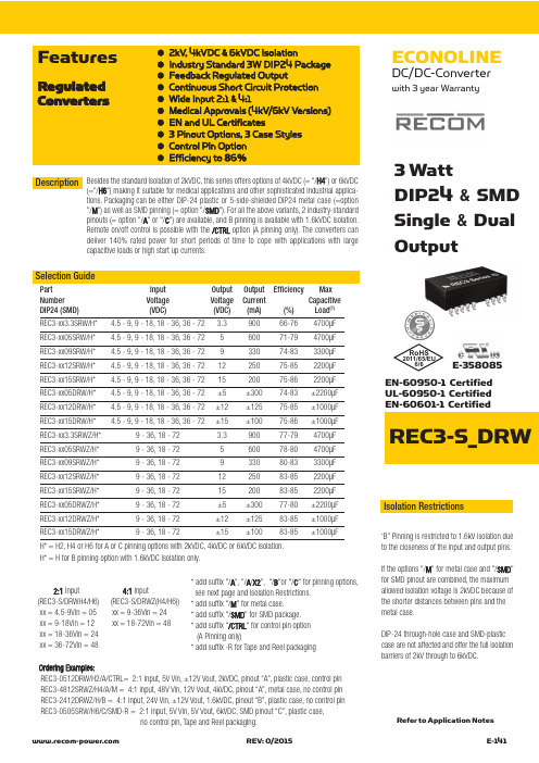
ECONOLINE DC DC 转换器说明书
ECONOLINEDC/DC-Converterwith 3 year WarrantyREC3-S_DRW●2kV, 4kVDC &6kVDC Isolation●Industry Standard 3W DIP24 Package ●Feedback Regulated Output●Continuous Short Circuit Protection ●Wide Input 2:1 & 4:1●Medical Approvals (4kV/6kV Versions)●EN and UL Certificates●3 Pinout Options, 3 Case Styles ●Control Pin Option ●Efficiency to 86%FeaturesRegulated Converters3 WattDIP24 & SMD Single &DualOutputEN-60950-1 Certified UL-60950-1 Certified EN-60601-1 CertifiedSelection GuidePart Input Output Output Efficiency Max Number Voltage Voltage Current Capacitive DIP24 (SMD)(VDC)(VDC)(mA)(%)Load (1)REC3-xx3.3SRW/H* 4.5 - 9, 9 - 18, 18 - 36, 36 - 72 3.390066-764700µF REC3-xx05SRW/H* 4.5 - 9, 9 - 18, 18 - 36, 36 - 72560071-794700µF REC3-xx09SRW/H* 4.5 - 9, 9 - 18, 18 - 36, 36 - 72933074-833300µF REC3-xx12SRW/H* 4.5 - 9, 9 - 18, 18 - 36, 36 - 721225075-852200µF REC3-xx15SRW/H* 4.5 - 9, 9 - 18, 18 - 36, 36 - 721520075-862200µF REC3-xx05DRW/H* 4.5 - 9, 9 - 18, 18 - 36, 36 - 72±5±30074-83±2200µF REC3-xx12DRW/H* 4.5 - 9, 9 - 18, 18 - 36, 36 - 72±12±12575-85±1000µF REC3-xx15DRW/H* 4.5 - 9, 9 - 18, 18 - 36, 36 - 72±15±10075-86±1000µF REC3-xx3.3SRWZ/H*9 - 36, 18 - 72 3.390077-794700µF REC3-xx05SRWZ/H*9 - 36, 18 - 72560078-804700µF REC3-xx09SRWZ/H*9 - 36, 18 - 72933080-833300µF REC3-xx12SRWZ/H*9 - 36, 18 - 721225083-852200µF REC3-xx15SRWZ/H*9 - 36, 18 - 721520083-852200µF REC3-xx05DRWZ/H*9 - 36, 18 - 72±5±30077-80±2200µF REC3-xx12DRWZ/H*9 - 36, 18 - 72±12±12583-85±1000µF REC3-xx15DRWZ/H*9 - 36, 18 - 72±15±10083-85±1000µFH* = H2, H4 or H6 for A or C pinning options with 2kVDC, 4kVDC or 6kVDC isolation.H* = H for B pinning option with 1.6kVDC isolation only.Besides the standard isolation of 2kVDC, this series offers options of 4kVDC (= "/H4") or 6kVDC(="/H6") making it suitable for medical applications and other sophisticated industrial a pplica-tions. Packaging can be either DIP-24 plastic or 5-side-shielded DIP24 metal case (=option "/M ") as well as SMD pinning (= option "/SMD "). For all the above variants, 2 industry-standard pinouts (= option "/A "or "/C ") are available, and B pinning is available with 1.6kVDC isolation.Remote on/off control is possible with the /CTRL option (A pinning only). The converters can deliver 140% rated power for short periods of time to cope with applications with large capacitive loads or high start up currents.Description 2:1Input 4:1Input(REC3-S/DRWH4/H6) (REC3-S/DRWZ(H4/H6))xx = 4.5-9Vin = 05 xx = 9-36Vin = 24xx = 9-18Vin = 12 xx = 18-72Vin = 48 xx = 18-36Vin = 24xx = 36-72Vin = 48*add suffix "/A ", "/A /X2", "/B "or "/C " for pinning options,see next page and Isolation Restrictions.*add suffix "/M " for metal case.* add suffix "/SMD " for SMD package.* add suffix "/CTRL " for control pin option (A Pinning only)* add suffix -R for Tape and Reel packagingIsolation Restrictions‘B” Pinning is restricted to 1.6kV isolation dueto the closeness of the input and output pins.If the options "/M " for metal case and "/SMD "for SMD pinout are combined, the maximum allowed isolation voltage is 2kVDC because of the shorter distances between pins and the metal case.DIP-24 through-hole case and SMD-plastic case are not affected and offer the full isolation barriers of 2kV through to 6kVDC.Ordering Examples:REC3-0512DRW/H2/A/CTRL= 2:1 input, 5V Vin, ±12V Vout, 2kVDC, pinout “A”, plastic case, control pin REC3-4812SRWZ/H4/A/M = 4:1 input, 48V Vin, 12V Vout, 4kVDC, pinout “A”, metal case, no control pin REC3-2412DRWZ/H/B = 4:1 input, 24V Vin, ±12V Vout, 1.6kVDC, pinout “B”, plastic case, no control pin REC3-0505SRW/H6/C/SMD-R = 2:1 input, 5V Vin, 5V Vout, 6kVDC, SMD pinout “C”, plastic case,no control pin, Tape and Reel packaging.Refer to Application NotesE-358085RoHS2011/65/EU6/6Input Voltage Range 2:1 & 4:1Output Voltage Accuracy ±2% max.Line Regulation (HL-LL)±0.4% max.Load Regulation (for output load current change from 20% to 100%)±0.6% max.Minimum Load 10% (2)Output Ripple and Noise (0,1µF capacitor on output, 20MHz BW)50mVp-p max.Switching Frequency at Full Load 2:1 Input types 90kHz min. / 150kHz max.and nominal Input Voltage 4:1 Input types 120kHz min. / 180kHz max.Input Filter Pi Network Efficiency at Full Load see above No Load Power Consumption 300mW max.Isolation Voltage H2-Suffix (tested for 1 second)2000VDC(rated for 1 minute**)1000VAC / 60HzIsolation Voltage H4-Suffix (tested for 1 second)4000VDC(rated for 1 minute**)2000VAC / 60HzIsolation Voltage H6-Suffix (tested for 1 second)6000VDC(rated for 1 minute**)3000VAC / 60HzIsolation Capacitance 2:1 Input types 20pF min. / 60pF max.4:1 Input types 40pF min. / 80pF max.Isolation Resistance 1 G Ωmin.Short Circuit Protection (Max temp. = 60°C during short circuit conditions)Continuous, Auto Restart Operating Temperature Range 5V input types -40°C to +80°C (see Graph)(free air convection)others -40°C to +85°C (see Graph)Storage Temperature Range -55°C to +125°C Relative Humidity 95% RH Case Material Non-Conductive Plastic or Metal Thermal Impedance Natural convection 20°C/W for plastic case12°C/W for metal casePackage Weight 13g Packing Quantity 15 pcs per Tube100 pcs per ReelMTBF (+25°C)using MIL-HDBK 217F 1043 x 103 hours (+85°C)using MIL-HDBK 217F 186 x 103 hours Certifications UL General Safety Report: E358085UL 60950-1 1st Ed.C22.2 No. 60950-1-03EN General Safety Report: SPCLVD1212007EN60950-1:2006 + A1:2010+A12:2011EN Medical Safety Report: MDD1205098-3 + RM1205098-3 IEC/EN 60601-1 3rd Ed.Medical Report + ISO14971 Risk AssessmentDerating-Graph(Ambient T emperature)Specifications (measured at T A = 25°C, nominal input voltage, full load and after warm-up)O u t p u t P o w e r (%)1201002060125750-40Operating Temperature (°C)0805025804010010550Safe Operating AreaTypical CharacteristicsE f f i c i e n c y %100040%0%100%40Efficiency / Load 60%80%20%206080Total Output current (%)E f f i c i e n c y%100040%0%100%40Efficiency / Load 60%80%20%206080Total Output current (%)E f f i c i e n c y %10040%0%100%40Efficiency / Load60%80%20%206080Total Output current (%)Dual 2:1 InputSingle 2:1 InputSingle 2:1 Input Vin = 5VO u t p u t P o w e r (%)1201002060125750-40Operating Temperature (°C)0805025854010010550Safe Operating Area}Detailed Information seeApplication Notes chapter "MTBF"R E C 3-R WNotes Note 1:Maximum capacitive load is defined as the capacitive load that will allow start up in under 1 second without damage to the converter Note 2:The REC3-RW series requires a minimum of 10% load on the output to maintain specified regulation. Operating under no-load conditions will not damage these devices; however, they may not meet all listed specifications.**Any data referred to in this datasheet are of indicative nature and based on our practical experience only. For further details, please refer to our Application Notes.REC3-RW“C” Pinning /H2, /H4 & /H6E f f i c i e n c y %100040%0%100%40Efficiency / Load 60%80%20%206080Total Output current (%)E f f i c i e n c y %100040%0%100%40Efficiency / Load 60%80%20%206080Total Output current (%)E f f i c i e n c y %100040%0%100%40Efficiency / Load 60%80%20%206080Total Output current (%)Dual 4:1 InputSingle 4:1 InputSingle 4:1 Input Typical Characteristics - ContinuedPackage Style and Pinning (mm) DIP 24 , Wide Input 2:1 & 4:1“A” Pinning /H2, /H4 & /H6Pin Connections Pin #Single Single/X2Dual 1 (option)CTRL CTRL CTRL 2–Vin –Vin –Vin 3–Vin –Vin –Vin 9NC No Pin Com 11NC NC –Vout 14+Vout +Vout+Vout 16–Vout –Vout Com 22+Vin +Vin +Vin 23+Vin+Vin+VinNC = No Connection CTRL OptionVin+0V22,232,31CTRL TTL Input1k W RECx-xxxx/CTRL1N4148OnOffON = Open or 0V< V ctrl <1.2V OFF = 2.2V< V ctrl<12VCTRL OptionRecommended Footprint Details1Bottom View121110213152324Pin Connections Pin #Single Dual 1+Vin +Vin 2+Vin +Vin 10NC Com 11NC Com 12–Vout NC 13+Vout –Vout 15NC +Vout 23–Vin –Vin 24–Vin–VinNC = No ConnectionXX.X ± 0.5 mm XX.XX ± 0.25 mmRecommended Footprint DetailsXX.X ± 0.5 mm XX.XX ± 0.25 mm1Bottom View12111032131415222324Recommended Footprint DetailsXX.X ± 0.5 mm XX.XX ± 0.25 mmPackage Style and Pinning (mm) DIP 24 , Wide Input 2:1 & 4:1SMD PinningRecommended Footprint DetailsSMD pin connections follow standard package A (/A/SMD), B (/B/SMD) or C (/C/SMD) pinning.All unused pins are NC(No Connection). See Below for detailed pinout listsPin Connections Pin #Single Dual 1 (Option) CTRLCTRL 2–Vin –Vin 3–Vin –Vin 4NC NC 5NC NC 9NC Com 10NC NC 11NC -Vout 12NCNCPin Connections Pin #Single Dual 13 NC NC 14+Vout +Vout 15NC NC 16-Vout Com 20NC NC 21NC NC 22+Vin +Vin 23+Vin +Vin 24NCNCPin Connections Pin #Single Dual 1 +Vin +Vin 2NC –Vout 3NC Com 4NC NC 5NC NC 9NC NC 10-Vout Com 11+Vout +Vout 12-Vin-VinPin Connections Pin #Single Dual 13 -Vin -Vin 14+Vout +Vout 15-Vout Com 16NC NC 20NC NC 21NC NC 22NC Com 23NC -Vout 24+Vin+VinPin Connections Pin #Single Dual 1 +Vin +Vin 2+Vin +Vin 3NC NC 4NC NC 5NC NC 9NC NC 10NC Com 11NC Com 12-VoutNCPin Connections Pin #Single Dual 13 +Vout -Vout 14NC NC 15NC +Vout 16NC NC 20NC NC 21NC NC 22NC NC 23-Vin -Vin 24-Vin-Vin/A/SMD Pinning/B/SMD Pinning/C/SMD PinningPin Connections Pin #Single Dual 1+Vin +Vin 2No Pin –Vout 3No Pin Com 10–Vout Com 11+Vout +Vout 12–Vin –Vin 13–Vin –Vin 14+Vout +Vout 15–Vout Com 22No Pin Com 23No Pin –Vout 24+Vin+VinNC = No Connection for all packages incl.SMD case the length of plastic case is 31,8 mm, length of metal case 32.0 mm“B” Pinning /H (1.6kV Only)R E C 3-R WThe product information and specifications are subject to change without prior notice. RECOM products are not authorized for use in safety-critical applications (such as life support) without RECOM’s explicitwritten consent. A safety-critical application is defined as an application where a failure of a RECOM product may reasonably be expected to endanger or cause loss of life, inflict bodily harm or damage property. The buyer shall indemnify and hold harmless RECOM, its affiliated companies and its representatives against any damage claims in connection with the unauthorized use of RECOM products in such safety-critical applications.。
REC10-4805SRWZH中文资料
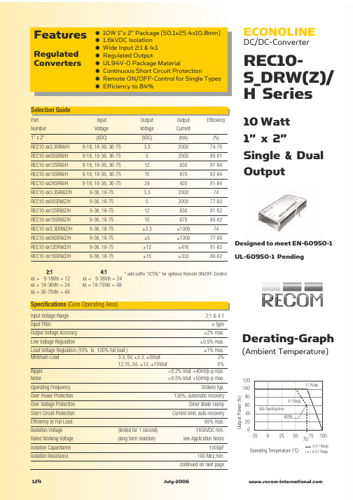
ECONOLINE
DC/DC-Converter
REC10S_DRW(Z)/ H Series
10 Watt 1” x 2” Single & Dual Output
Selection Guide
Part Number 1” x 2” REC10-xx3.3SRW/H REC10-xx05SRW/H REC10-xx12SRW/H REC10-xx15SRW/H REC10-xx24SRW/H REC10-xx3.3SRWZ/H REC10-xx05SRWZ/H REC10-xx12SRWZ/H REC10-xx15SRWZ/H REC10-xx3.3DRWZ/H REC10-xx05DRWZ/H REC10-xx12DRWZ/H REC10-xx15DRWZ/H 2:1 xx = 9-18Vin = 12 xx = 18-36Vin = 24 xx = 36-75Vin = 48 Input Voltage (VDC) 9-18, 18-36, 36-75 9-18, 18-36, 36-75 9-18, 18-36, 36-75 9-18, 18-36, 36-75 9-18, 18-36, 36-75 9-36, 18-75 9-36, 18-75 9-36, 18-75 9-36, 18-75 9-36, 18-75 9-36, 18-75 9-36, 18-75 9-36, 18-75 Output Voltage (VDC) 3.3 5 12 15 24 3.3 5 12 15 ±3.3 ±5 ±12 ±15 Output Current (mA) 2000 2000 830 670 420 2000 2000 830 670 ±1000 ±1000 ±416 ±333 (%) 74-76 80-81 81-84 82-84 81-84 74 77-80 81-82 80-82 74 77-80 81-82 80-82 Efficiency
普瑞蓝功率芯片自制中文规格书
普瑞蓝功率芯片规格书BXCE45×45MILB XCE 45 x 45 mil 特点•高流明输出和效率•使用寿命长•增加目前蔓延痕迹高效和统一的照明•100%测试和排序的波长,功率与正向电压•朗伯发射模式•兼容焊锡膏,焊锡瓶坯或银环氧裸片粘接•交付中等粘性的蓝色胶带(20CM±为10mm×20厘米±10MM)应用范围•普通照明•路灯•便携式照明•建筑照明•定向照明•广域照明•显示背光•数码相机闪光灯•汽车照明•白光LEDLED芯片结构图产品命名方式:B XC E 4 5 4 5 X X X – Y Y – ZBXCE:指定产品系列4545:指定芯片尺寸(45 MIL×45 MIL)XXX:指定主导波长YY:指定辐射功率Z:指定正向电压机械尺寸6。
磁带应存放在垂直方向,而不是水平堆放。
磁带堆叠可以放置过大的压力,对LED的焊盘,导致焊线实力降低。
环保法规:普瑞致力于固态照明市场提供环保产品。
普瑞BXCE4545蓝色功率芯片是符合欧盟对电子设备的指令,即RoHS指令对有害物质的限制。
普瑞不会故意对BXCE4545模具产品添加以下限制材料:铅,汞,镉,六价铬,多溴联苯(PBB)或多溴二苯醚(PBDE)关于普瑞:普瑞是由40亿美金升值到100亿美金的全球照明行业的技术和解决方案的领先开发商和制造商。
总部设在加利福尼亚州利弗莫尔,普瑞是固态照明(SSL)的先驱,发光二极管(LED)技术,扩大市场,拉低了LED照明系统的成本。
普瑞的专利灯源技术取代与整合,固态照明解决方案,使灯具和照明设备制造商,以高的性能和迅速增长的能源效率的白色光(如白炽灯,卤素灯,荧光灯和高强度放电照明)传统技术内部和外部照明市场,包括路灯,商业照明和消费电子应用。
普瑞是与500多个专利申请或授予全球唯一垂直整合的LED制造商和专门开发固态光源照明行业设计的解决方案。
ZH-400规格书

Ver. 2.0
深圳市众辉科技有限公司
11/12
液晶拼接驱动板卡 ZH-400
Product Specification
结构尺寸
Ver. 2.0
深圳市众辉科技有限公司
12/12
CN8、CON9(10PIN/2.54) 电源24V输入接口
端口 1-5 6-10
说明 24V直流输入 24V直流输入地
CN5(6PIN/2.0) 12V背光接口
端口 1、2 3 4 5、6 说明 12V直流输出 ON/OFF,H-ON,L-OFF ADJ,H-亮,L-暗 地
CN18(3PIN/2.54) 风扇接口
液晶拼接驱动板卡 ZH-400
Product Specification
SPECIFICATION FOR APPROVAL
( ) Preliminary Specification ( ◆ ) Final Specification
Title
BUYER MODEL
液晶拼接驱动板卡
SUPPLIER *MODEL SUFFIX *When you obtain standard approval, please use the above model name without suffix 深圳市众辉科技有限公司 ZH-400
Ver. 2.0
深圳市众辉科技有限公司
9/12
液晶拼接驱动板卡 ZH-400
Product Specification
J1(20PIN/2.54) 24V背光接口
端口 3-6,13-16 7-10,17-20 1,11 2,12
说明 24V直流输出 直流输出地 ADJ (屏幕亮度控制) ON/OFF (屏幕背光开关控制)
瑞萨MCU型号速查手册
2010年4月1日 瑞萨电ቤተ መጻሕፍቲ ባይዱ公司
【发行】瑞萨电子公司() 【业务咨询】/inquiry
Notice
1. All information included in this document is current as of the date this document is issued. Such information, however, is subject to change without any prior notice. Before purchasing or using any Renesas Electronics products listed herein, please confirm the latest product information with a Renesas Electronics sales office. Also, please pay regular and careful attention to additional and different information to be disclosed by Renesas Electronics such as that disclosed through our website.
瑞萨MCU型号速查手册

SSOP-20 SOP-20
家电、OA设备、民用设备
M34508G4H-XXXFP/GP
○○
4509
M34509G4FP M34509G4-XXXFP
M34509G4HFP M34509G4H-XXXFP
--
4096W
256W
6MHz/ 1.8V~5.6V
0.5us @6MHz
18 - - ○ -
10位×6
M37546G4GP/HP/SP M37546G4-XXXGP/HP/SP
8K 16K
384
8MHz/ 1.8~5.5V
0.25us @8MHz
25 - - ○ ○ ○ ○ 10位×6
-
2 2 ○ ○ ○ ○ - - ○ ○ ○ - - 12 -20~85
512
SDIP-32 LQFP-32
WQFN-36
2K
60K
2.5K
照相机、音频设备、家电、民用设备
3850A
M38503G4AFP/SP M38503G4A-XXXFP/SP
16K
512
12.5MHz/ 1.8~5.5V
0.32us @12.5MHz
34
-
○
-
-
-
-
10位×9
-
4 - - - ○ ○ - - ○ ○ ○ - - 6 -20~85
SDIP-42 SSOP-42
75
芯片封装说明
78
QzROM
720、740工具
低功耗
R8C族及工具
M16C
R32C
M16C族工具 SuperH族及工具 安全MCU
78K
V850
78K、V850工具 芯片封装说明
英飞凌 DD800S45KL3_B5 高绝缘等级模块 数据表
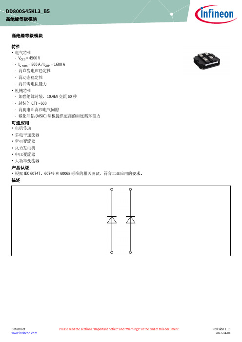
高绝缘等级模块特性•电气特性-V CES = 4500 V-I C nom = 800 A / I CRM = 1600 A -高直流电压稳定性-高动态稳定性-高冲击电流能力•机械特性-加强绝缘封装,10.4kV 交流 60 秒-封装的 CTI > 600-高爬电距离和电气间隙-碳化硅铝 (AlSiC) 基板提供更高的温度循环能力可选应用•电机传动•多电平逆变器•牵引变流器•风力发电机•中压变流器•大功率变流器产品认证•根据 IEC 60747、60749 和 60068标准的相关测试,符合工业应用的要求。
描述DD800S45KL3_B5高绝缘等级模块内容描述 . . . . . . . . . . . . . . . . . . . . . . . . . . . . . . . . . . . . . . . . . . . . . . . . . . . . . . . . . . . . . . . . . . . . . . . . . . . . . . . . . . . . . . . . .1特性 . . . . . . . . . . . . . . . . . . . . . . . . . . . . . . . . . . . . . . . . . . . . . . . . . . . . . . . . . . . . . . . . . . . . . . . . . . . . . . . . . . . . . . . . .1可选应用 . . . . . . . . . . . . . . . . . . . . . . . . . . . . . . . . . . . . . . . . . . . . . . . . . . . . . . . . . . . . . . . . . . . . . . . . . . . . . . . . . . . .1产品认证 . . . . . . . . . . . . . . . . . . . . . . . . . . . . . . . . . . . . . . . . . . . . . . . . . . . . . . . . . . . . . . . . . . . . . . . . . . . . . . . . . . . .1内容 . . . . . . . . . . . . . . . . . . . . . . . . . . . . . . . . . . . . . . . . . . . . . . . . . . . . . . . . . . . . . . . . . . . . . . . . . . . . . . . . . . . . . . . . .2 1封装 . . . . . . . . . . . . . . . . . . . . . . . . . . . . . . . . . . . . . . . . . . . . . . . . . . . . . . . . . . . . . . . . . . . . . . . . . . . . . . . . . . . . . . . . .3 2二极管,逆变器 . . . . . . . . . . . . . . . . . . . . . . . . . . . . . . . . . . . . . . . . . . . . . . . . . . . . . . . . . . . . . . . . . . . . . . . . . . . . . . .3 3特征参数图表 . . . . . . . . . . . . . . . . . . . . . . . . . . . . . . . . . . . . . . . . . . . . . . . . . . . . . . . . . . . . . . . . . . . . . . . . . . . . . . . .5 4电路拓扑图 . . . . . . . . . . . . . . . . . . . . . . . . . . . . . . . . . . . . . . . . . . . . . . . . . . . . . . . . . . . . . . . . . . . . . . . . . . . . . . . . . .7 5封装尺寸 . . . . . . . . . . . . . . . . . . . . . . . . . . . . . . . . . . . . . . . . . . . . . . . . . . . . . . . . . . . . . . . . . . . . . . . . . . . . . . . . . . . .8 6模块标签代码 . . . . . . . . . . . . . . . . . . . . . . . . . . . . . . . . . . . . . . . . . . . . . . . . . . . . . . . . . . . . . . . . . . . . . . . . . . . . . . . .9修订历史 . . . . . . . . . . . . . . . . . . . . . . . . . . . . . . . . . . . . . . . . . . . . . . . . . . . . . . . . . . . . . . . . . . . . . . . . . . . . . . . . . . .10免责声明 . . . . . . . . . . . . . . . . . . . . . . . . . . . . . . . . . . . . . . . . . . . . . . . . . . . . . . . . . . . . . . . . . . . . . . . . . . . . . . . . . . .111封装表 1绝缘参数特征参数代号标注或测试条件数值单位绝缘测试电压V ISOL RMS, f = 50 Hz, t = 60 s10.4kV 局部放电熄弧电压V isol RMS, f = 50 Hz, Q PD typ. 10 pC 3.5kV DC 稳定性V CE(D)T vj=25°C, 100 Fit3000V 模块基板材料AlSiC内部绝缘基本绝缘 (class 1, IEC 61140)AlN爬电距离d Creep端子至散热器64.0mm 爬电距离d Creep端子至端子56.0mm 电气间隙d Clear端子至散热器40.0mm 电气间隙d Clear端子至端子26.0mm 相对电痕指数CTI > 600表 2特征值特征参数代号标注或测试条件数值单位最小值典型值最大值杂散电感,模块L sCE25nH 模块引线电阻,端子-芯片R AA'+CC'T C=25°C, 每个开关0.51mΩ储存温度T stg-55125°CM6, 螺丝 4.25 5.75Nm 模块安装的安装扭距M根据相应的应用手册进行安装M8, 螺丝810Nm 端子安装扭矩M根据相应的应用手册进行安装重量G1000g 注:Dynamic Data valid in conjunction with FZ800R45KL3_B5 module2二极管,逆变器表 3最大标定值特征参数代号标注或测试条件数值单位反向重复峰值电压V RRM T vj = -40 °C4500VT vj = 25 °C4500T vj = 125 °C4500连续正向直流电流I F800A (待续)表 3(续) 最大标定值特征参数代号标注或测试条件数值单位正向重复峰值电流I FRM t P = 1 ms1600A I2t-值I2t t P = 10 ms, V R = 0 V T vj = 125 °C255kA²s 最大损耗功率P RQM T vj = 125 °C1600kW 最小开通时间t onmin10µs表 4特征值特征参数代号标注或测试条件数值单位最小值典型值最大值正向电压V F I F = 800 A, V GE = 0 V T vj = 25 °C 2.50 3.10VT vj = 125 °C 2.50 3.00反向恢复峰值电流I RM V R = 2800 V, I F = 800 A,V GE = -15 V, -di F/dt =3300 A/µs (T vj = 125 °C)T vj = 25 °C1000A T vj = 125 °C1150恢复电荷Q r V R = 2800 V, I F = 800 A,V GE = -15 V, -di F/dt =3300 A/µs (T vj = 125 °C)T vj = 25 °C770µC T vj = 125 °C1400反向恢复损耗(每脉冲)E rec V R = 2800 V, I F = 800 A,V GE = -15 V, -di F/dt =3300 A/µs (T vj = 125 °C)T vj = 25 °C1200mJ T vj = 125 °C2400结-外壳热阻R thJC每个二极管25.5K/kW 外壳-散热器热阻R thCH每个二极管, λgrease= 1 W/(m*K)21.0K/kW 允许开关的温度范围T vj op-50125°C4电路拓扑图图 15封装尺寸图 26 模块标签代码6模块标签代码图 3修订历史修订历史修订版本发布日期变更说明V1.02014-06-23Target datasheetV3.02016-05-31Final datasheetV3.12018-01-15Final datasheetn/a2020-09-01Datasheet migrated to a new system with a new layout and new revisionnumber schema: target or preliminary datasheet = 0.xy; final datasheet =1.xy1.102022-04-04Final datasheet商标所有参照产品或服务名称和商标均为其各自所有者的财产。
W78E58中文
W78E58B规格书8位微控制器目录:1.概述 (3)2.特性 (3)3.管脚配置 (4)4.管脚描述 (5)5.方块图 (7)6.功能描述 (8)6.1 RAM (8)6.2 定时器0,1,2 (8)6.3 时钟 (9)6.4 晶体振荡器 (9)6.5 外部时钟 (9)6.6 电源管理 (9)6.7 减少EMI辐射 (9)6.8 复位 (9)6.9 I/O口4 (11)6.10 INT2/INT3 (12)6.11 P4口基地址寄存器 (14)6.12 在线编程(ISP)模式 (15)6.13 在线编程控制寄存器(CHPCON) (17)6.14 F04KBOOT 模式(从LDROM启动) (18)7.保密位 (22)7.1 锁止位 (22)禁止 (22)7.2 MOVC7.3 加密 (22)8.电气特性 (23)8.1 绝对最大额定值 (23)8.2 DC特性 (23)出版日期: December 22, 20048.3 AC特性 (25)8.3.1时钟输入波形 (25)8.3.2程序读取周期 (26)8.3.3数据读取周期 (26)8.3.4数据写周期 (27)8.3.5端口访问周期 (27)9.时序波形图 (28)9.1 程序读取周期 (28)9.2 数据读周期 (28)9.3 数据写周期 (29)9.4 端口访问周期 (29)10.典型应用电路 (30)10.1 扩展的外部程序存储器和石英晶体 (30)10.2 扩展的外部程序存储器和振荡器 (31)11.封装尺寸 (32)11.1 DIP40 (32)11.2 44 管脚PLCC (33)11.3 44 管脚PQFP (34)12.应用指南 (35)12.1 ISP 软件编程示例: (35)13.文件版本描述 (42)1. 概述W78E58B是具有带ISP功能的Flash EPROM的低功耗8位微控制器;ISP功能的Flash EPROM可用于固件升级。
澳德玛产品使用说明书样本

电子防潮箱的技术说明● 数码显示箱内温度湿度, 红色为温度, 绿色为湿度, 其中温度湿度显示为箱内的实际情况, 温度会比环境温度高1~3度。
In the digital cabinet, red means temperature, green means humidity.● ADMA 表示中湿度电子防潮箱, ADMB 表示低湿度电子防潮箱, ADMC 表示超低湿电子防潮箱,ADMD 表示氮气柜。
所有型号后面带”F ”为防静电电子防潮箱。
ADMAshows middle humidity dry cabinet. ADMB shows low humidity dry cabinet. ADMC shows ultra-low humidity dry cabinet. ADMD shows nitrogen gas cabinet.● 本产品箱体表面涂层已经经过ROHS 认证。
The surface coating has acquired ROHS certificate.● 如型号变动增加, 恕另不通知。
If we design a new style, please understand that we will not notice.1. 防潮箱须放置在水平坚固的表面Place the dry-cabinet on a level and strong surface. Turn the adjuster to be balance.2. 放置好箱体内搁板, 高度可根据存放物品调至适合, 搁板扣如图放入。
The height of the shelf is adjustable for the convenient of storage, and the shelf clasp should be put as drawing.3. 防潮箱背面留一定空间, 距离墙或其它物品必须5CM 以上。
REC3-4805SRWZ中文资料
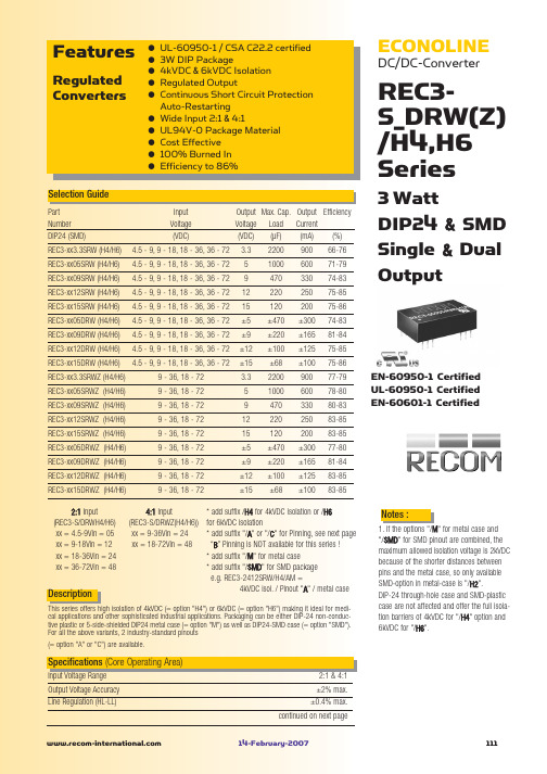
Safe Operating Area
100 50 75 125 80 105 Operating Temperature (°C) 0 25
Output Power (%)
-55°C to +125°C 95% RH Non-Conductive Plastic 20°C/W for metal case 13g 1043 x 10 hours 186 x 103 hours
3 Watt DIP24 & SMD Single & Dual Output
EN-60950-1 Certified UL-60950-1 Certified EN-60601-1 Certified
Description
4:1 Input * add suffix /H4 for 4kVDC isolation or /H6 (REC3-S/DRWZ(H4/H6)) for 6kVDC isolation xx = 9-36Vin = 24 * add suffix "/A" or "/C" for Pinning, see next page xx = 18-72Vin = 48 “B” Pinning is NOT available for this series ! * add suffix "/M" for metal case * add suffix "/SMD" for SMD package e.g. REC3-2412SRW/H4/AM = 4kVDC isol. / Pinout "A" / metal case
Notes :
1. If the options "/M" for metal case and "/SMD" for SMD pinout are combined, the maximum allowed isolation voltage is 2kVDC because of the shorter distances between pins and the metal case, so only available SMD-option in metal-case is "/H2". DIP-24 through-hole case and SMD-plastic case are not affected and offer the full isolation barriers of 4kVDC for "/H4" option and 6kVDC for "/H6".
纽扣电池型号对照表
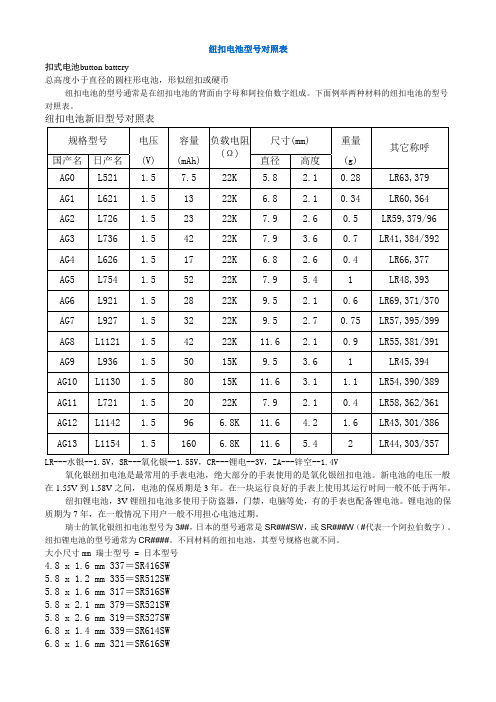
纽扣电池型号对照表扣式电池button battery总高度小于直径的圆柱形电池,形似纽扣或硬币纽扣电池的型号通常是在纽扣电池的背面由字母和阿拉伯数字组成。
下面例举两种材料的纽扣电池的型号对照表。
纽扣电池新旧型号对照表LR---水银--1.5V,SR---氧化银--1.55V,CR---锂电--3V,ZA---锌空--1.4V氧化银纽扣电池是最常用的手表电池,绝大部分的手表使用的是氧化银纽扣电池。
新电池的电压一般在1.55V到1.58V之间,电池的保质期是3年。
在一块运行良好的手表上使用其运行时间一般不低于两年。
纽扣锂电池,3V锂纽扣电池多使用于防盗器,门禁,电脑等处,有的手表也配备锂电池。
锂电池的保质期为7年,在一般情况下用户一般不用担心电池过期。
瑞士的氧化银纽扣电池型号为3##,日本的型号通常是SR###SW,或SR###W(#代表一个阿拉伯数字)。
纽扣锂电池的型号通常为CR####。
不同材料的纽扣电池,其型号规格也就不同。
大小尺寸mm 瑞士型号 = 日本型号4.8 x 1.6 mm 337=SR416SW5.8 x 1.2 mm 335=SR512SW5.8 x 1.6 mm 317=SR516SW5.8 x 2.1 mm 379=SR521SW5.8 x 2.6 mm 319=SR527SW6.8 x 1.4 mm 339=SR614SW6.8 x 2.1 mm 364=SR621SW6.8 x 2.6 mm 377=SR626SW7.9 x 1.2 mm 346=SR712SW7.9 x 1.4 mm 341=SR714SW7.9 x 1.6 mm 315=SR716SW7.9 x 2.1 mm 362=SR721SW7.9 x 2.6 mm 397=SR726SW7.9 x 3.1 mm 329=SR731SW7.9 x 3.6 mm 384=SR741SW7.9 x 5.4 mm 309=SR754SW9.5 x 1.6 mm 373=SR916SW9.5 x 2.1 mm 371=SR920SW9.5 x 2.6 mm 395=SR927SW9.5 x 3.6 mm 394=SR936SW11.6 x 1.6 mm 366=SR1116SW11.6 x 2.1 mm 381=SR1120SW11.6 x 3.1 mm 390=SR1130SW11.6 x 3.6 mm 344=SR1136SW11.6 x 4.2 mm 301=SR1143SW11.6 x 5.4 mm 303=SR1144SW锂-二氧化锰纽扣电池型号对照表——CR系列其型号AG为日本标准,SR为国际标准型号纽扣电池也叫扣式电池是指外形尺寸象一颗小纽扣的电池一般来说直径较大厚度较薄(相对于柱状电池如市场上的5号AA等电池);纽扣电池是从外形上来对电池来分同等对应的电池分类有柱状电池方形电池异形电池;纽扣电池一般来说常见的有充电的和不充电的两种充电的包括3.6V可充锂离子扣式电池(LIR系列)3V可充锂离子扣式电池(ML或VL系列);不充电的包括3V锂锰扣式电池(CR系列)及1.5V碱性锌锰扣式电池(LR及SR系列);纽扣电池的型号名称前面的英文字母表示电池的种类数字表示尺寸前两位数字表示直径后两位表示厚度; 纽扣电池因体形较小直径从4.8mm至30mm厚度从1.0mm至7.7mm不等;一般用于各类电子产品的后备电源,如电脑主板,电子表,电子词典,电子秤,记忆卡,遥控器,电动玩具等;以下每一行均代表同一电池(仅供参考):AG0 LR69 379 SR521AG1 LR621 364 SR621 164AG2 LR726 396 SR726 196AG3 LR41 392 SR41 192AG4 LR626 377 SR626 177AG5 LR754 393 SR754 193AG6 LR920 371 SR927 171AG7 LR927 395 SR927 195AG8 LR55 391 SR1120 191 LR1120AG9 LR936 394 SR936 194AG10 LR54 389 SR1130 189 LR1130AG11 LR721 362 SR721 162AG12 LR43 386 SR43 186 LR1142AG13 LR44 357 SR44 A76 LR1154337 SR416321 SR616315 SR716362 SR721373 SR916371 SR920特性:1,氧化银电池有“SR××”及“SR××SW”两个系列。
德国瑞德GW系列用户使用说明书

2 安全.............................................................5 2.1 遵守指导说明................................................ 5 2.2 警告标志和符号解释........................................5 2.3 避免危险...................................................... 5 2.4 预期用途...................................................... 5 2.5 操作安全的基本说明........................................6
4.9 连接燃气管,针对燃气类型检查燃烧器设置........... 20 4.9.1 燃气管连接的重要说明...............................20 4.9.2 连接燃气管...............................................20 4.9.3 进入设备内部...........................................20 4.9.4 检查燃烧器的预先设置...............................21
K4T51163QC-ZCE6资料

K4T51083QC K4T51163QC
512Mb DDR2 SDRAM
512Mb C-die DDR2 SDRAM Specification
60FBGA & 84FBGA with Pb-Free (RoHS compliant)
INFORMATION IN THIS DOCUMENT IS PROVIDED IN RELATION TO SAMSUNG PRODUCTS, AND IS SUBJECT TO CHANGE WITHOUT NOTICE.
* Samsung Electronics reserves the right to change products or specification without notice.
1 of 29
Rev. 1.9 March 2007
元器K4件T5交10易43网
K4T51083QC K4T51163QC
2. Samsung products are not intended for use in life support, critical care, medical, safety equipment, or similar applications where Product failure could result in loss of life or personal or physical harm, or any military or defense application, or any governmental procurement to which special terms or provisions may apply.
NOTHING IN THIS DOCUMENT SHALL BE CONSTRUED AS GRANTING ANY LICENSE, EXPRESS OR IMPLIED, BY ESTOPPEL OR OTHERWISE,
RECOM R5M 5W 隔离 DC DC 电源说明书

DC/DC ConverterDescriptionThe R5M is an isolated 5W DC/DC converter in a compact SMD package available with 4:1 inputs covering 12, 24 and 48V rails providing single or dual regulated, short-circuit protected outputs. There is no minimum load requirement. Isolation is 1.6kVDC/1min, and the operating temperature is from -40°C up to +50°C without derating. Class A and Class B EMC conformity requires only a few external components. Standard packaging is tube.FeaturesRegulated Converters•5W power in SMD package •4:1 Input voltage range •Efficiency up to 86%• 1.6kVDC/1min isolation •Regulated output•-40°C to +50°C at full load•Continuous short circuit protectedR5MSelection GuideModel NumberingY E A Rwa r r a n ty3RoHS 2+compliant 10 from 10Specifications (measured @ Ta= 25°C, nom. Vin, full load and after warm-up unless otherwise stated)Part Input nom. Output Output Efficiency max. CapacitiveNumber Voltage Range (1) Voltage Current typ. (2)Load(3)[VDC] [VDC] [mA] [%] [µF]R5M-xx3.3S/SMD 9-36, 18-75 3.3 1000 774400 R5Mxx05S/SMD 9-36, 18-75 5 1000 812200R5Mxx09S/SMD 9-36, 18-759 55582 1470R5M-xx12S/SMD 9-36, 18-7512 42084-851220 R5M-xx15S/SMD 9-36, 18-7515 333 85-861000R5M-xx24S/SMD 9-36, 18-7524 21082470R5M-xx05D/SMD 9-36, 18-75±5 ±500 82±1000 R5M-xx12D/SMD 9-36, 18-75±12 ±210 84±680 R5M-xx15D/SMD9-36, 18-75±15±168 85±440Notes:Note1: Refer to “Input Voltage Range”Note2: Efficiency is tested at nominal input and full load at +25°C ambient Note3: Max Cap Load is tested at nominal input and full resistive loadBASIC CHARACTERISTICSParameterConditionMin.Typ.Max.Input Voltage Range nom. V IN = 24VDC 9VDC 24VDC 36VDC nom. V IN = 48VDC18VDC48VDC75VDC Input Surge Voltage1 second max.nom. V IN = 24VDC 50VDC nom. V IN = 48VDC 100VDCcontinued on next pageCase Style S ingle/D ualnom. Input Voltage nom. Output VoltageR5M-/SMD5 WattSMDSingle & Dual Outputp re li mi n a rySpecifications (measured @ Ta= 25°C, nom. Vin, full load and after warm-up unless otherwise stated)Specifications (measured @ Ta= 25°C, nom. Vin, full load and after warm-up unless otherwise stated)REGULATIONSParameterConditionValueOutput Accuracy ±1.0% max.Line Regulationlow line to high line, full load±0.2% max.Load Regulation0% to 100% loadsingle 1% max.dual 1% max.10% to 90% loadsingle 0.5% max.dual0.8% max.Cross Regulation asymmetrical 25% / 100% load±5% max.Transient Response Recovery Time25% load step change±500µs typ.PROTECTIONSParameterTypeValueShort Circuit Protection (SCP)continuous, auto recoveryIsolation Voltage (5)I/P to O/P1 minute1.6kVDC min.Isolation Resistance I/P to O/P , V ISO = 500VDC 1G Ω min.Isolation CapacitanceI/P to O/P , 100kHz/0.1V50pF typ.Notes:Note5: This power module is not internally fused. An input line fuse must always be used Recom suggests: 24Vin=T1.25A; 48Vin=T0.63A slow blowp re li mSpecifications (measured @ Ta= 25°C, nom. Vin, full load and after warm-up unless otherwise stated)ENVIRONMENTALParameterConditionValueOperating Temperature Range with derating -40°C to +105°C without derating -40°C to +50°CMaximum Case Temperature measured at “tc point”+105°COperating Humidity non-condensing5% - 95% RH max.Thermal Shock according to MIL-STD-810FVibration according to MIL-STD-810FMTBFaccording to MIL-HDBK-217F, G.B.+25°C2959 x 10³ hoursDerating Graph(@ Chamber and natural convection 0.1m/s)-40-20020407060-30-101030508090120110100100806040907050302010O u t p u t L o a d [%]Ambient Temperature [°C]105i mi n a rySpecifications (measured @ Ta= 25°C, nom. Vin, full load and after warm-up unless otherwise stated)PACKAGING INFORMATIONParameterTypeValuePackaging Dimension (LxWxH)tube 218.0 x 17.2 x 19.9mmPackaging Quantity20pcsStorage Temperature Range non-condensing-55°C to +125°C Storage Humidity5% to 95% RH max.The product information and specifications may be subject to changes even without prior written notice.The product has been designed for various applications; its suitability lies in the responsibility of each customer. The products are not authorized for use in safety-critical applications without RECOM’s explicit written consent. A safety-critical application is an application where a failure may reasonably be expected to endanger or cause loss of life, inflict bodily harm or damage property. The applicant shall indemnify and hold harmless RECOM, its affiliated companies and its representatives against any damage claims in connection with the unauthorizeduse of RECOM products in such safety-critical applications.p r。
切割机操作说明书中文讲解

瑞洲RZCAM平板系列电脑切割机用户手册User's Manual佛山市南海瑞洲科技有限公司FOSHAN NANHAI RUIZHOU TECHNOLOGY CO., LTD.RZCAM电脑切割机主视图:RZCAM平板系列电脑切割机是专为鞋样/服装/箱包/手袋等行业样板切割而设计的自动化数控设备。
切割机采用了自主研发的嵌入式数控系统、美国进口的CPU和精密的电子元件,其稳定性和操作性达到国内外领先技术水平;切割机采用进口直线导轨结合进口同步带传动,切割精度完全达到往返原点零误差;切割速度可达60-80cm/s,安全稳定,清晰的双行液晶显示,数控界面美观大方,标准I/O接口,支持HP-GL和GP-GL格式,可连接任意CAD软件,操作简单易学;目前已广泛应用于制鞋、服装、箱包手袋等行业的样板切割。
当您购买了RZCAM电脑切割机平板系列任何机型后,请务必认真详细阅读本手册,以便您能正确和安全地使用本产品并充分了解它的性能。
一、切割机结构与工作原理RZCAM切割机由以下部分组成:切割机支架 + 切割机平台 +RZCAM数控系统 + 传动机构 + 切割机头(刀笔自动切换)1、本机的整体设计由专业的机械设计师设计,流线型的外观、方便灵活的机台支架装配了可自由移动的滑轮,客户在使用过程中如想换位,只要打开轮锁,轻轻推动切割机就可摆到自己想要更换的位置,方便实用。
2、此机的切割平台装置多组水平调节机构,在切割平面水平调节中可随时根据切割平面的要求、调整调节水平,克服了切割机出厂后不能再调节平台的缺点。
3、本机采用自主研发的嵌入式数控系统、美国进口的CPU和精密的电子元件,操作界面简单易学,稳定性和操作性达到国内外领先技术水平。
4、传动部份的稳定平滑运行直接决定切割机的切割输出品质,本机采用进口直线导轨作为X、Y方向的运动结构、结合进口同步带,切割精度达到更加精密 (X系列机型除外)。
5、本机切割头采用刀、笔自动切换装置的新型技术,意指笔线画完之后自动切换到半刀切割,半刀割完之后自动切换到全刀切割。
3CWE480资料

Key Benefits Long-Range, Cost-Effective Wireless Connectivity Between Sitesbuildings, portable or temporary classrooms, and temporary networks. And if your company’s network requirements or location change, the wireless building-to-building bridge can be easily relocated.High PerformanceWith our wireless building-to-building bridge, you get high-speed, long-range connections. In fact, you’ll get throughput exceeding that of two dedicated T1 lines. Plus, you won’t have to worry about expensive leased-line service that’s actually slower than this wireless bridge.Flexible ConnectionsWith point-to-point and point-to-multipoint connectivity options, our wireless building-to-building bridge lets you transfer information between two buildings or multiple buildings across campus. What’s more, you can choose the antenna option that best fits your needs—get transmissions up to 1300 meters with omni-directional antennas, and 4100 meters using sector panel antennas.Figure 1. Point-to-multipoint connections fromone to multiple buildings using omni-directional antennas.Figure 2. Point-to-point connections from one building to another using sector panel antennas.Simple ManagementThe easy-to-use graphical interface reduces management burdens. Manage all of your bridges from anywhere on the same subnet, or do it over the Internet using telnet. Easily align antennas with real-time signal strength reporting and usage data. Plus, default settings make configura-tion simple—all you have to do is hook them up.Complete SecurityWhen you choose our wireless building-to-building bridge, you don’t have to worry about security. Support for both 40- and 128-bit WEP encryp-tion lets users exchange information privately. Plus, our bridge uses a3Com proprietary protocol to encapsu-late data. This protocol ensures the wireless bridge will not interfere with VPN or other protocols—so your encrypted data passes right through. Cost EffectiveNow you can connect all of those hard-to-wire locations for less. With our building-to-building bridge, you don’t have to worry about running expensive and tough-to-install leased lines or fiber-optic cabling. Just connect your wired LANs to wireless building-to-building bridges, or connect a remote building-to-building bridge to a 3Com 11 Mbps Wireless LAN access point. In minutes, you’ve interconnected a remote site with the central site. Best yet, this hardware investment can pay for itself, when compared to the money you would have spent on leased-line service.2Networking on a Tight Budget When to BuyOur building-to-building bridge isideal for organizations who:•Are looking for a cost-effectivealternative to leased lines.•Don’t want to invest in layingexpensive and tough-to-installcables since their network require-ments or location may change.•Want a simple way to connectremote and hard-to-wire locations—between office buildings that aren’talready connected to one another,portable classrooms and cross-cam-pus office buildings, and buildingsseparated by other structures suchas bridges or freeways.One-Year Limited Warranty3Com warrants your wirelessbuilding-to-building bridge to be ingood working order for one yearwhile owned by the original end user.Customer SupportQuick access to support informationis available on 3Com’s Web site atJill, a fictional principal for FairmontHigh, is excited for the schooladdition—three computer labs, 15classrooms, and more. But that’s twoyears off. Classrooms are bursting atthe seams. More students are on theway. And 50 new computers need to benetworked. Is it possible on theschool’s budget? Yes.Using our building-to-buildingbridges, she turned one of three newportable classrooms into a computer laband gave the others network access—without running cables. She connectedone bridge to the school network andanother to an access point in theportable computer lab. Now all of thenew computers, including those inportable classrooms, have access tonetwork resources and the Internet.Just like you’d expect—a simplesolution from 3Com.3Product Features802.11b Data Rates Supported 11, 5.5, 2, 1 MbpsRangeTransmit and receive informa-tion up to 4100 meters between wireless building-to-building bridges, depending on the antenna selected.Network StandardIEEE 802.11bNetwork Connection Type10BASE-TNetwork Architecture Types Bridge 802.3 to 802.11bNumber of Users/Bridge UnlimitedWireless Bridges/LAN Unlimited Frequency Band2.4 GHzWireless MediumDSSSMedia Access ProtocolCSMA/CAModulationDSSSOperating Channels1 through 11 (U.S.)Receive Sensitivity11 Mb: -81 dBm5.5 Mb: -84 dBm2 Mb: -85 dBm1 Mb: -87 dBmAvailable Transmit PowerSettings300 mw, typicallyAntennaMultiple antenna options letyou ensure the optimal signalstrength for your environment.Encryption40- and 128-bit WEPencryption, shared keySecurityVPN pass throughLEDsPower: greenWireless: green whenassociated; yellow whentransmitting/receivingEthernet: green whenconnected; yellow when activityis detectedAlert: amberSerial: green when RX; yellowwhen TXSpecifications43Com Corporation, 5400 Bayfront Plaza, P .O. Box 58145, Santa Clara, CA 95052-8145To learn more about 3Com products and services, visit . 3Com Corporation is publicly traded on Nasdaq under the symbol COMS.Copyright © 2001 3Com Corporation. All rights reserved. 3Com, AirConnect, and XJACK are registered trademarks and the 3Com logo is a trademark of 3Com Corporation. All other company or product names may be trademarks of their respective companies. All specifications are subject to change without notice.Printed in U.S.A.400698-001 06/01Product Name For use in…Order Number3Com ®11 Mbps Wireless LAN building-to-building bridge Canada/U.S.3CRWE90096A Product Accessories For use in…Order Number 3Com 4 dBi omni-directional antenna, up to 2600 meters; point-to-multipoint Canada/U.S.3CWE4903Com 8 dBi omni-directional antenna, up to 4100 meters; point-to-multipoint Canada/U.S.3CWE4913Com 13 dBi sector panel antenna, up to 4100 meters; point-to-point Canada/U.S.3CWE4953Com 18 dBi sector panel antenna, up to 4100 meters (typically paired with50 ft cable accessory); point-to-point Canada/U.S.3CWE4963Com 6-Foot Antenna Cable Canada/U.S.3CWE4803Com 20-Foot Antenna Cable Canada/U.S.3CWE4813Com 50-Foot Antenna Cable Canada/U.S.3CWE482Ordering Information *Data throughput can vary depending on several factors, including network traffic load, distance between bridges, and antennas used.Remote Configuration Support GUI, Telnet Local Configuration GUI, serial console Bridging Protocol MAC layer encapsulation Dimensions Length: 251 mm (9.9 in)Width: 157 mm (6.2 in)Thickness: 25 mm (1 in)Safety Compliance Canada, the U.S.:UL1950/CSA 22.2Europe: CE Marked Radio/Electromagnetic Conformance Compliance US: FCC Part 15B&C Canada: Industry Canada RSS-210European Community: ETS 300328, ETS 300 826Australia: C-Tick Environmental Operating Ranges Operating temperature: -20 to 55˚C Storage temperature: -20 to 70˚C Altitude: Up to 3 km.Humidity: 10 to 95%noncondensing Service and Support One-year limited warranty Specifications,continuedThe 3Com 11 Mbps Wireless LAN building-to-building bridge complements these 3Com WirelessLAN products for simple, reliable, and secureconnections:•3Com 11 Mbps Wireless LAN Access Point 6000•3Com 11 Mbps Wireless LAN PC Card withXJACK ®antenna•3Com AirConnect ®11 Mbps Wireless LANaccess point•3Com AirConnect 11 Mbps Wireless LANPC Card•3Com AirConnect 11 Mbps Wireless LANPCI card•3Com Ethernet Client bridge。
三星维修手册共5页
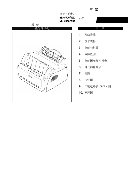
维 修激光打印机目 录1. 预防措施 2. 技术规格 3. 分解和组装 4. 故障检测 5. 分解图和部件列表 6. 电气部件列表 7. 框图 8. 接线图9. 印刷电路板(PCB )图 10. 原理图三 星激光打印机ML-4500/XEU ML-4500/DSG手册4.维护与故障排除4-1 预防性维护下述循环周期为保养通用指南。
示例表用于平均每天接收与传输50份文件。
环境条件4-2打印质量第 1 页4-3 DCU(诊断器)控制4-3-1 DCU设置DCU用于诊断打印机故障。
使用DCU之前,首先打开并除去打印机前部出口盖,然后从左边除去底盖。
将DCU排插线(10针至4针)连接到控制板上的CN9(4针)。
4-3-2 状态代码将DCU连接到打印机上,然后打开电源。
DCU用7段发光二极管显示状态代码。
有两种状态代码:正常与错误。
状态代码表示打印机的运行状态。
正常状态代码错误状态代码4-3-3 诊断方式当打印机故障发生且DCU显示错误状态代码时,您可以使用诊断模式查找问题并进行修理。
诊断代码当您修理故障时,您可以仅使机器的一个单元在诊断模式下运行。
同时按下三个按钮([DOWN],[SHIFT],[STOP]),打开打印机电源,进入诊断模式。
当DCU显示‘78’,2-3秒后放开这些按键,接着DCU显示‘00’。
通过使用[UP]或[SHIFT]与[DOWN]键,选择适宜的诊断模式,然后按下[ENTER]键运行。
如欲停止运行,按下[SHIFT]与[ENTER]第 3 页4-3-4自测试按钮当您按下此按钮,机器打印‘竖行’样张。
当您按下此按钮并接通打印机电源,DCU显示代码‘89’,同时打印机预热。
预热之后,打印机处于‘准备’状态。
DCU显示代码‘88’。
在此模式下,所有传感器不运行,打印机进行所有打印操作(打印演示样张)与打印PC数据)。
如果诊断打印引擎有故障时的控制板,此模式非常有用。
希望以上资料对你有所帮助,附励志名言3条::1、世事忙忙如水流,休将名利挂心头。
常用纽扣电池型号对照表

常用纽扣电池型号对照表常用纽扣电池型号对照表香港国际瑞士日本其他电压直径Ф*厚度(mm)用途AG0 LR69 379 SR521 1.5V 5.8*2.1AG1 LR621 364 SR621 164 1.5V 6.8*2.1AG2 LR726 396 SR726 196 1.5V 7.9*2.6AG3 LR41 392 SR41 192 1.5V 7.9*3.6 迷你手电、体温计AG4 LR626 377 SR626 177 1.5V 6.8*2.6AG5 LR754 393 SR754 193 1.5V 7.9*5.4AG6 LR920 371 SR927 171 1.5V 9.5*2.1AG7 LR927 395 SR927 195 1.5V 9.5*2.6AG8 LR55 391 SR1120 191 1.5V 11.6*2.1AG9 LR936 394 SR936 194 1.5V 9.5*3.6AG10 LR54 389 SR1130 189 1.5V 11.6*3.1 计算器AG11 LR721 362 SR721 162 1.5V 7.9*2.1AG12 LR43 386 SR1142 186 1.5V 11.6*4.2 计算器、计步器AG13 LR44 357 SR1154 A76 1.5V 11.6*5.4 手表、计算机CR2032 3V 20*3.2 体重秤、主板CR2025 3V 20*2.6 电子词典CR2016 3V 20*1.6 手表,计算机、电子记事簿CR2032是指一种20mm直径,3.2mm高。
型号命名与标识IEC型号美国型号日本型号中国传统叫法直径(mm) 高度(mm)普通锌锰电池R03 AAA UM-4 7号电池10.5 44.5 R6P AA UM-3 5号电池14.5 50.5 R14 C UM-2 2号电池26.2 50.0 R20 D UM-1 1号电池34.2 61.5碱性锌锰电池LR03 AAA AM-4 7号碱性电池10.5 44.5 LR6 AA AM-3 5号碱性电池14.5 50.5 LR14 C AM-2 2号碱性电池26.2 50.0 LR20 D AM-1 1号碱性电池34.2 61.5IEC标准中,R代表圆柱形,L代表碱性,数字代表电池的大小,数字后面的P代表高功率,这里有一个特殊规定,在表示五号普通锌锰电池时,要标识为R6P,而不是R06或者R6。
- 1、下载文档前请自行甄别文档内容的完整性,平台不提供额外的编辑、内容补充、找答案等附加服务。
- 2、"仅部分预览"的文档,不可在线预览部分如存在完整性等问题,可反馈申请退款(可完整预览的文档不适用该条件!)。
- 3、如文档侵犯您的权益,请联系客服反馈,我们会尽快为您处理(人工客服工作时间:9:00-18:30)。
ECONOLINE
DC/DC-Converter
REC3S_DRW(Z) /H4,H6 Series
66-76 71-79 74-83 75-85 75-86 74-83 81-84 75-85 75-86 77-79 78-80 80-83 83-85 83-85 77-80 81-84 83-85 83-85
14-February-2007
111
元器件交易网
ECONOLINE
DC/DC-Converter
Specifications (Core Operating Area)
Load Regulation (for output load current change from 20% to 100%) Output Ripple and Noise (0,1µF capacitor on output, 20MHz BW) Switching Frequency at Full Load 2:1 Input types and nominal Input Voltage 4:1 Input types Input Filter Efficiency at Full Load No Load Power Consumption Isolation Voltage Rated Working Voltage Isolation Voltage Rated Working Voltage Isolation Capacitance Isolation Resistance Short Circuit Protection Operating Temperature Range (free air convection) Storage Temperature Range Relative Humidity Case Material Thermal Impedance Package Weight MTBF (+25°C) (+85°C) Natural convection using MIL-HDBK 217F using MIL-HDBK 217F 5V input types others H4 types (see note) H6 types (see note) (tested for 1 second) (long term isolation) (tested for 1 second) (long term isolation) 2:1 Input types 4:1 Input types
Specifications (Core Operating Area)
Input Voltage Range Output Voltage Accuracy Line Regulation (HL-LL) 2:1 & 4:1 ±2% max. ±0.4% max. continued on next page
(Ambient Temperature)
120 100 80 60 50 40 20 0 -40
Vin = 5V
300mW max. 4000VDC min. see Application Notes 6000VDC min. see Application Notes 20pF min. / 60pF max. 40pF min. / 80pF max. 1 GΩ min. Continuous, Auto Restart -40°C to +80°C (see Graph) -40°C to +85°C (see Graph)
Selection Guide
Part Number DIP24 (SMD) REC3-xx3.3SRW (H4/H6) REC3-xx05SRW (H4/H6) REC3-xx09SRW (H4/H6) REC3-xx12SRW (H4/H6) REC3-xx15SRW (H4/H6) REC3-xx05DRW (H4/H6) REC3-xx09DRW (H4/H6) REC3-xx12DRW (H4/H6) REC3-xx15DRW (H4/H6) REC3-xx3.3SRWZ (H4/H6) REC3-xx05SRWZ (H4/H6) REC3-xx09SRWZ (H4/H6) REC3-xx12SRWZ (H4/H6) REC3-xx15SRWZ (H4/H6) REC3-xx05DRWZ (H4/H6) REC3-xx09DRWZ (H4/H6) REC3-xx12DRWZ (H4/H6) REC3-xx15DRWZ (H4/H6) 2:1 Input (REC3-S/DRWH4/H6) xx = 4.5-9Vin = 05 xx = 9-18Vin = 12 xx = 18-36Vin = 24 xx = 36-72Vin = 48 Input Voltage (VDC) 4.5 - 9, 9 - 18, 18 - 36, 36 - 72 4.5 - 9, 9 - 18, 18 - 36, 36 - 72 4.5 - 9, 9 - 18, 18 - 36, 36 - 72 4.5 - 9, 9 - 18, 18 - 36, 36 - 72 4.5 - 9, 9 - 18, 18 - 36, 36 - 72 4.5 - 9, 9 - 18, 18 - 36, 36 - 72 4.5 - 9, 9 - 18, 18 - 36, 36 - 72 4.5 - 9, 9 - 18, 18 - 36, 36 - 72 4.5 - 9, 9 - 18, 18 - 36, 36 - 72 9 - 36, 18 - 72 9 - 36, 18 - 72 9 - 36, 18 - 72 9 - 36, 18 - 72 9 - 36, 18 - 72 9 - 36, 18 - 72 9 - 36, 18 - 72 9 - 36, 18 - 72 9 - 36, 18 - 72 Output Max. Cap. Output Efficiency Voltage Load Current (VDC) (µF) (mA) (%) 3.3 5 9 12 15 ±5 ±9 ±12 ±15 3.3 5 9 12 15 ±5 ±9 ±12 ±15 2200 1000 470 220 120 ±470 ±220 ±100 ±68 2200 1000 470 220 120 ±470 ±220 ±100 ±68 900 600 330 250 200 ±300 ±165 ±125 ±100 900 600 330 250 200 ±300 ±165 ±125 ±100
Typical Characteristics
Single 2:1 Input Single 2:1 Input
Efficiency / Load
100 80 60 40
This series offers high isolation of 4kVDC (= option "H4") or 6kVDC (= option "H6") making it ideal for medical applications and other sophisticated industrial applications. Packaging can be either DIP-24 non-conductive plastic or 5-side-shielded DIP24 metal case (= option "M") as well as DIP24-SMD case (= option "SMD"). For all the above variants, 2 industry-standard pinouts (= option "A" or "C") are available.
元器件交易网
Features
Regulated Converters
● ● ● ● ● ● ● ● ● ●
UL-60950-1 / CSA C22.2 certified 3W DIP Package 4kVDC & 6kVDC Isolation Regulated Output Continuous Short Circuit Protection Auto-Restarting Wide Input 2:1 & 4:1 UL94V-0 Package Material Cost Effective 100% Burned In Efficiencyrea
100 50 75 125 80 105 Operating Temperature (°C) 0 25
Output Power (%)
-55°C to +125°C 95% RH Non-Conductive Plastic 20°C/W for metal case 13g 1043 x 10 hours 186 x 103 hours
3
}
Detailed Information see Application Notes chapter "MTBF"
120 100 80 60 50 40 20 0 -40
Safe Operating Area
0
25
50 75
100 85 105
125
Operating Temperature (°C)
3 Watt DIP24 & SMD Single & Dual Output
EN-60950-1 Certified UL-60950-1 Certified EN-60601-1 Certified
Description
4:1 Input * add suffix /H4 for 4kVDC isolation or /H6 (REC3-S/DRWZ(H4/H6)) for 6kVDC isolation xx = 9-36Vin = 24 * add suffix "/A" or "/C" for Pinning, see next page xx = 18-72Vin = 48 “B” Pinning is NOT available for this series ! * add suffix "/M" for metal case * add suffix "/SMD" for SMD package e.g. REC3-2412SRW/H4/AM = 4kVDC isol. / Pinout "A" / metal case
