650-36R-3C-5.5中文资料
650-36R-2C-5.5中文资料
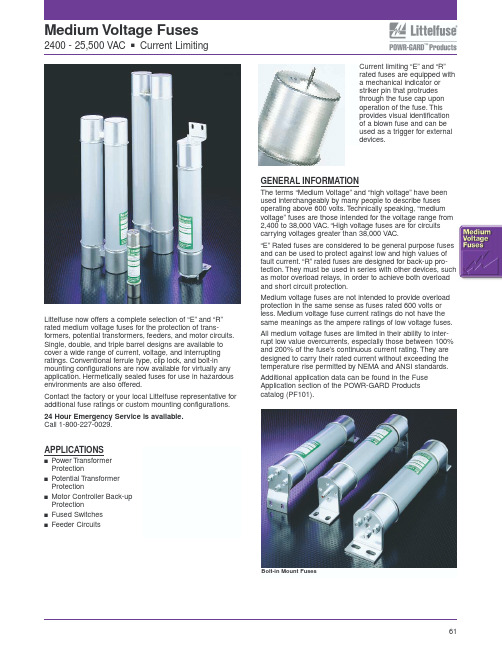
Littelfuse now offers a complete selection of “E”and “R”rated medium voltage fuses for the protection of trans-formers, potential transformers, feeders, and motor circuits.Single, double, and triple barrel designs are available to cover a wide range of current, voltage, and interrupting ratings.Conventional ferrule type, clip lock, and bolt-in mounting configurations are now available for virtually any application.Hermetically sealed fuses for use in hazardous environments are also offered.Contact the factory or your local Littelfuse representative for additional fuse ratings or custom mounting configurations.24 Hour Emergency Service is available.Call 1-800-227-0029.APPLICATIONSsPower T ransformer ProtectionsPotential T ransformer ProtectionsMotor Controller Back-up Protections Fused Switches sFeeder CircuitsGENERAL INFORMATIONThe terms “Medium Voltage”and “high voltage”have been used interchangeably by many people to describe fuses operating above 600 volts.T echnically speaking, “medium voltage”fuses are those intended for the voltage range from 2,400 to 38,000 VAC.“High voltage fuses are for circuits carrying voltages greater than 38,000 VAC.“E”Rated fuses are considered to be general purpose fuses and can be used to protect against low and high values of fault current.“R”rated fuses are designed for back-up pro-tection.They must be used in series with other devices, such as motor overload relays, in order to achieve both overload and short circuit protection.Medium voltage fuses are not intended to provide overload protection in the same sense as fuses rated 600 volts or less.Medium voltage fuse current ratings do not have the same meanings as the ampere ratings of low voltage fuses.All medium voltage fuses are limited in their ability to inter-rupt low value overcurrents, especially those between 100%and 200% of the fuse’s continuous current rating.They are designed to carry their rated current without exceeding the temperature rise permitted by NEMA and ANSI standards.Additional application data can be found in the Fuse Application section of the POWR-GARD Products catalog (PF101).Current limiting “E”and “R”rated fuses are equipped with a mechanical indicator or striker pin that protrudes through the fuse cap upon operation of the fuse.This provides visual identification of a blown fuse and can be used as a trigger for external devices.Bolt-in Mount Fuses15,500 voltsHermitically sealed for use in hazardous locationssuffix to part number)FIGURE 4FIGURE 5FIGURE 6Add “w ”suffix to part number for hookeye attachment .Bolt-In Mount “BI”FIGURE 11FIGURE 12FIGURE 1371Potential T ransformer (PT) fuses are current limiting fuses with high interrupting ratings designed for the protection of potential transformers.Application Note:When applying fuses for the protection of transformers, the magnetizing current inrush must be considered.The characteristics of the inrush, which can be matched with a fuse ’s time-current curve, should be available from the transformer manufacturer.”,Mounting clips are available 72。
5M0365R中文资料

Features
• Precision Fixed Operating Frequency (100/67/50kHz) • Low Start-up Current(Typ. 100uA) • Pulse by Pulse Current Limiting • Over Current Protection • Over Voltage Protection (Min. 25V) • Internal Thermal Shutdown Function • Under Voltage Lockout • Internal High Voltage Sense FET • Auto-Restart Mode
Characteristic KA5M0365RN, KA5L0365RN Maximum Drain Voltage Drain-Gate Voltage (RGS=1MΩ) Gate-Source (GND) Voltage Drain Current Pulsed (1) Continuous Drain Current (Ta=25°C) Continuous Drain Current (Ta=100°C) Single Pulsed Avalanche Energy (2) Maximum Supply Voltage Analog Input Voltage Range
bias
Good logic
9V
5µA1mA2.5R R+OSC
− +
S Q
R
L.E.B
0.1V
7.5V −
+
Thermal S/D
27V − OVER VOLTAGE S/D
S Q
R
Power on reset
瑞信功放产品介绍
PoP-Click 杂音抑制 支持单端和差分输入,可以随心所欲设计 灵活设计,外围简单。 超强抗干扰能力
Page 5
MC4890
1.0W 单声道A/B类 Audio PA
工作电压: 2.5V-5.5V 输出功率: 1.0W@1% THD+N Vdd=5V RL=8Ω THD+N 0.04%@5V 8Ω Po=0.5W Shoutdown 电流0.1uA 热保护功能 封装 :MSOP8/SOP8封装
封装
:TSSOP24
无输出滤波器 调制频率310KHz POP声抑制 高达90%工作效率 短路和热保护自动恢复,带喇叭保护功能 四段增益控制 符合RoHS标准的无铅封装
Page 20
MD4181
4Ω 3.3W低EMI AB/D切换式(F类) Audio PA
工作电压: 2.5V-5.5V 输出功率: 3.4W@10% THD+N Vdd=5.0V RL=4Ω 5.0W@10% THD+N Vdd=5.0V RL=2Ω 1.7W@10% THD+N Vdd=3.7V RL=4Ω 2.4W@10% THD+N Vdd=3.7V RL=2Ω 封装 :ESOP8L
智能切换对FM无干扰,高效率,音质优 输出功率高 ESOP封装时为5W(2Ω负载) 掉电模式漏电流小 外部增益可调,集成反馈 兼容LM4871 符合RoHS标准的无铅封装
Page 21
MD4206
2X3W立体声F 类 Audio PA
工作电压: 2.5V-5.5V 输出功率: 3.1W@10% THD+N Vdd=5.0V RL=4Ω(D类) 2.9W@10% THD+N Vdd=5.0V RL=2Ω(F类) 封装 :SOP16
ARRI 650 4和300 4 Fresnel 照明套件说明书

2 1l.76700.G 2 L2.76973.0 2 571140 2 571150
2 571152
4 570050 571195
650W fresnel barndoor filter frame 650W FRK lamp 6 5/8" full
single scrim 65/8" full
PHOTOMETRIC DATA: (U 16.4 ft
Beam Angle Beam Diameter Intensity
SPOT 20° 3.6 ft 153 fc
FLOOD
60° 11.5 ft 36 fc
ARRll000W
Manua I or pole operation
Weight: 8.3 Ibs Size : 8.9" (L) 10" (W) 13.6" (H) Lens: 5.1 " Lamp: 1OOOW EGT
500 ROUTE 303, BLAUVELT, NY 10913 TWX 7105752624
600 NO. VICTORY BLVD. , BURBANK, CA 91502 TWX 9104984641
FAX (914) 425-1250 FAX (818) 848-4028
(914) 353-1400 (818) 841-7070
PHOTOMETRIC DATA: @ 16.4 ft
Beam Angle Beam Diameter Intensity
SPOT 14° 3.9 ft 534 fc
FLOOD
60° 19 ft 111 fc
ARRISOOOW
Manual or pole operation
RSS-0505中文资料

2.54
RSD-0505 RECOM ****
0.50±0.5
2.57
RSS-0505 RECOM
0.50±0.5
Pin Connections Pin # 1 2 4 5 7 8 10 Single –Vin +Vin –Vout +Vout No Pin NC No Pin Dual –Vin +Vin Com -Vout +Vout No Pin NC
8.20 14.70 5.40 1.65 0.20 2.54 x 4 15.24 5.35 1.65 12.10 0.20 2.54 x 3 12.75 7.40 9.00 11.10 7.90
NC = No Connection
Recommended Footprint Details
10 12.00 1 2
Output Power (Watts) 2.0 1.5 1.0 Safe Operating Area 0.5 0 -40 0 50 100 125 150 85 Operating Temperature ˚C
元器件交易网
元器件交易网
ECONOLINE - DC/DC-Converter
RSS / RSD Series, 1 Watt, SMD (Single & Dual Output) Features
● ● ●
ቤተ መጻሕፍቲ ባይዱ
1kVDC Isolation Efficiency to 78% Power Density 1.8W/cm3
● ● ●
UL 94V-0 Package Material Toroidal Magnetics Internal SMD Construction
RCR-650A iVD650 产品说明书
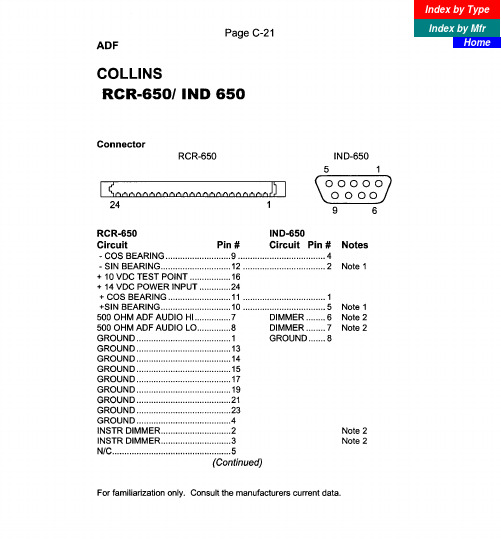
For familiarization only. Consult the manufacturers current data.
volts out 13 to voltage converter, 14 volts in 25. 4. For 14 volts, 48 to Dimmer, 20 ground. For 28 volts, 20 to Dimmer, 18 open.
Index by Type
Index by Mfr Home
N/C.. ..............................................
.6
SENSE ANTENNA ......................... 18
X LOOP ANTENNA.. ..................... .22
Y LOOP ANTENNA.. ..................... .20
20
N/C.. ...............................................
I
N/C.. ..............................................
.I0
N/C.. ..............................................
Notes 1. For top mount antenna, reverse 2. For 14 volts, 7 and 3 to Dimmer,
Dimmer, 7 and 3 open.
2 and 5. 6 and 2 to ground.
For 28 volts, 6 and 2 to
2SC3356R25中文资料(NEC)中文数据手册「EasyDatasheet - 矽搜」
–150˚ –120˚
–30˚ –150˚
–60˚ –90˚
–120˚
–30˚
–60˚ –90˚
Data Sheet PU10209EJ02V0DS
5
10
插入最功大率可增5用益功|率SV增益=M1A0GV(分贝)
I 能力= 20 mA
0 0.05 0.1 0.2
0.5
1
2
频率f(GHz)
5 插入功率增益| S
0
0.5 1
5
集电极电流I
10 (mA)
50 70
备注
该图表显示标称特性.
Data Sheet PU10209EJ02V0DS
3
芯片中文手册,看全文,戳
2%
2. 收藏家基地电容,当发射器接地
hFE 分类
秩 打标
h值
R23/Q R23
50至100
R24/R R24
80至160
R25/S R25
125至250
注意 旧规格/新规格
MIN.
TYP. MAX.
单元
–
–
1.0
µA
–
–
1.0
µA
50
120
250
–
–
7
–
GHz
–
11.5
–
dB
–
1.1
2.0
dB0.55订源自信息零件号2SC3356 2SC3356-T1B
数量
50只(不卷) 3千件/卷
供给方式
•8mm宽压花录音 •引脚3(集电极)面带穿孔方
备注
要订购评价样品,请联系您最近销售部门. 单位样品数量为50个.
绝对最大额定值(T
AC650系列一般目的逆变器产品介绍说明书

AC650 Series General Purpose Inverter AC Inverters 0.25kW–110kWBright Backlit LCD Display Diagnostic or Parameter Indicator Motor Rotating and Direction Indicator Local Start Raise/Lower SpeedAC650 SeriesAC Inverters 0.25kW–110kWThe AC650 series, comprising of AC650 General Purpose and AC650V General Purpose High Performance, have been specifically designed to provide simple, no-fuss speed control of standard three phase AC induction motors from 0.25kW to 110kW.Designed with a full range of useful features includingpre-programmed applications, integrated EMC filter and options for local or remote mountable operator controls – the drivesare simple to set-up, install and operate.With the AC650 series you are in control of your application immediately – no complicated set-up procedures, no confusing menu navigation; just quick and easy operation straight from the box.Product OverviewSystemsProcessSimple1000kW110kW7.5kWAC Drives Product OverviewAC650 General Purpose Ratings 0.25kW–7.5kWWhether you need to control a conveyor belt, automatic barrier, machine spindle, or other general purpose application, the AC650 delivers reliable, cost-effective voltage/frequency speed control of your motor. Designed with simplicity in mind the AC650 comes in a compact format with DIN rail mounting as standard allowing easy integration into any electrical control panel. The operator/programmingkeypad can be removed to prevent unauthorised changes to inverter configuration.For simple motor speed control up to 7.5kW, the AC650 is an easy to use, out of the box solution that will have your system up and running in no time.Standard part reference includes EMC filter and operator keypad Remote mounting of operator keypad requires additional cable. Part No. CM057375U300 (3m length)AC650V General Purpose – High PerformanceRatings 0.25kW–110kWThe AC650V expands upon the simple, no-fuss philosophy of the AC650 and provides reliable, robust motor control from0.25kW through to 110kW. With the addition of sensorless flux vector technology, the AC650V allows improved control at lower speeds, better speed regulation of variable loads and higher starting torques for high inertia systems. The variable torque configuration option above5.5kW makes the AC650V ideally suited to energy saving in pumpand fan applications.*Variable torque rating for centrifugal pump and fan applicationsStandard part reference includes operator keypad and integrated EMC filter up to 7.5kW. Footprint filters available above 7.5kWSpecificationsPower SupplySingle phase units;220-240Vac ± 10%, 50-60Hz ± 5%Three phase units;380-460Vac ± 10%, 50-60Hz ± 5%Ambient0-40°C (derate to 50°C)Up to 1000m ASL (derate > 1000m) IP20 protectedOverload150% Constant torque ratings110% Variable torque rating (pump and fan)Output Frequency0-240HzStandardsThe AC650 series meets the following standards when installed in accordance with the relevant product manual.• CE Marked to EN50178 (Safety, Low Voltage Directive).• CE Marked to EN61800-3 (EMC Directive).• UL listed to US standard UL508C.• cUL listed to Canadian standard C22.2 #14.Inputs/OutputsAnalogue Inputs2; Speed Control.0-10V, 0-10V/4-20mA (summing)Analogue Outputs1; User configurable output frequency/load 0-10V Digital Inputs3–AC650, 5–AC650V; User configurable start/stop/direction/ pre-set speeds (8)Digital Input/Outputs1–AC650, 2–AC650V; User configurable as inputs or outputs Digital Relay Outputs 1; Relay output 4A @ 240VAll digital outputs configurable for; at (not at) speed/at (above) min speed/running (stopped)/healthy (tripped)/above (below) pre-set loadMotor Thermistor Input Power Supply Outputs24V dc (50mA) – Digital I/O supply10V dc (10mA) – Analogue reference supplyCommunications OptionsRS485/RS232 – AC650V and 650 PROFIBUS – AC650V onlyUser Selectable Pre-programmed Application MacrosSimply select your relevant application and the drives inputs/outputs and parameter list is automatically configured for you.• Basic Speed Control –voltage or current source speed demand with digital start/stop and direction.• Manual/Auto Control –switch between a local or remote speed demand signal.• Preset Speeds –select up to 8 preprogrammed speeds selected by digital inputs.• Raise/Lower –increase and decrease speed from raise/lower digital inputs.• PID Control –control pressure, flow, temperature or other variable by monitoring transducerfeedback.Correct at time of going to press.Frame C, D, E, FFrame 1,2,3Sales OfficesCatalogue HA469992 (Issue 2 April 2008)© 2008 Parker Hannifin Corporation. All rights reserved.Parker Hannifin Ltd SSD Drives DivisionNew Courtwick Lane, Littlehampton, West Sussex BN17 7RZ United KingdomTel: +44 (0) 1903 737 000 Fax: +44 (0) 1903 737 100***********************AustraliaParker Hannifin Pty Ltd9 Carrington RoadPrivate Bag 4, Castle Hill NSW 1765Tel: +61 2 9634 7777 Fax: +61 2 9899 6184BelgiumParker Hannifin SA NVParc Industriel Sud Zone 11 23, Rue du BosquetNivelles B -1400 Belgium Tel: +32 67 280 900 Fax: +32 67 280 999BrasilParker Hannifin Ind. e Com. Ltda. Av. Lucas Nogueira Garcez, 2181 Esperança - Caixa Postal 148 Tel: +55 0800 7275374 Fax: +55 12 3954 5262CanadaParker Motion and Control 160 Chisholm Drive MiltonOntario L9T 3G9Tel: +1(905)693 3000 Fax: +1(905)876 1958ChinaParker Hannifin Motion & Control (Shanghai) Co. Ltd. SSD Drives280 Yunqiao RoadExport Processing Zone Pudong District Shanghai 201206 P.R.ChinaTel: +86 (21) 5031 2525 Fax: +86 (21) 5854 7599FranceParker SSD Parvex 8 Avenue du Lac B.P. 249F-21007 Dijon Cedex Tel: +33 (0)3 80 42 41 40 Fax: +33 (0)3 80 42 41 23GermanyParker Hannifin GmbH Von-Humboldt-Strasse 10 64646 Heppenheim GermanyTel: +49(0)6252 798200 Fax: +49(0)6252 798205IndiaSSD Drives India Pvt Ltd 151 Developed Plots Estate Perungudi,Chennai, 600 O96, India Tel: +91 44 43910700 Fax: +91 44 43910700ItalyParker Hannifin SPA Via Gounod 120092 Cinisello Balsamo Milano ItalyTel: +39 02 361081 Fax: +39 02 36108400SingaporeParker Hannifin Singapore Pte Ltd 11, Fourth Chin Bee Rd Singapore 619702 Tel: +65 6887 6300 Fax: +65 6265 5125SpainParker Hannifin (Espana) S.A. Parque Industrial Las Monjas Calle de las Estaciones 8 28850 Torrejonde Ardoz Madrid SpainTel: +34 91 6757300 Fax: +34 91 6757711SwedenParker Hannifin AB Montörgatan 7SE-302 60 Halmstad SwedenTel: +46(35)177300 Fax: +46(35)108407UKParker Hannifin Ltd. Tachbrook Park Drive Tachbrook Park Warwick CV34 6TUTel: +44(0)1926 317970 Fax: +44(0)1926 317980USAParker Hannifin Corp. SSD Drives Division 9225 Forsyth Park Drive CharlotteNorth Carolina 28273-3884 Tel: +1(704)588 3246 Fax: +1(704) 588-3249Your local authorised Parker distributor*HA469992*Printed in England. HA469992Issue 2 April 2008.©2008 Parker Hannifin Limited.。
struers duramin-650 半自动通用硬度计使用手册说明书
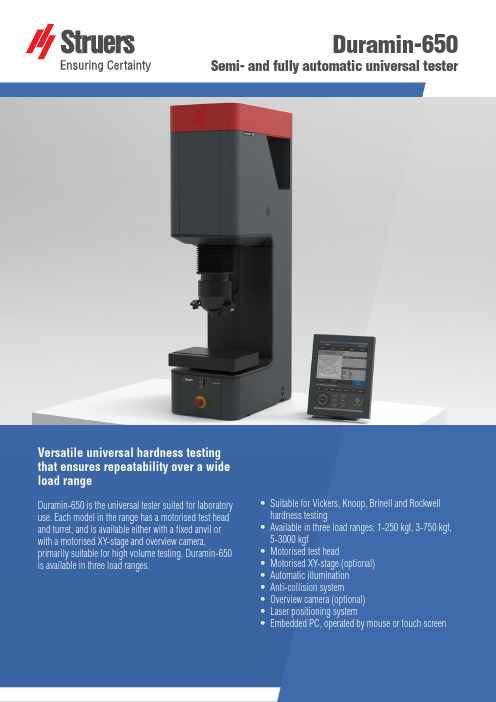
Duramin-650Semi- and fully automatic universal testerVersatile universal hardness testingthat ensures repeatability over a wideload rangeDuramin-650 is the universal tester suited for laboratory use. Each model in the range has a motorised test head and turret, and is available either with a fixed anvil or with a motorised XY-stage and overview camera, primarily suitable for high volume testing. Duramin-650 is available in three load ranges.• S uitable for Vickers, Knoop, Brinell and Rockwell hardness testing• A vailable in three load ranges: 1-250 kgf, 3-750 kgf, 5-3000 kgf• M otorised test head• M otorised XY-stage (optional)• A utomatic illumination• A nti-collision system• O verview camera (optional)• L aser positioning system• E mbedded PC, operated by mouse or touch screenAUSTRALIA & NEW ZEALAND Struers Australia27 Mayneview StreetMilton QLD 4064AustraliaPhone +61 7 3512 9600Fax +61 7 3369 8200****************** BELGIUM (Wallonie)Struers S.A.S.370, rue du Marché RollayF- 94507 Champignysur Marne CedexTéléphone +33 1 5509 1430Télécopie +33 1 5509 1449****************** BELGIUM (Flanders)Struers GmbH Nederland Zomerdijk 34 A3143 CT MaassluisTelefoon +31 (10) 599 7209 Fax +31 (10) 5997201********************** CANADAStruers Ltd.7275 West Credit Avenue Mississauga, Ontario L5N 5M9 Phone +1 905-814-8855Fax +1 905-814-1440****************CHINAStruers Ltd.No. 1696 Zhang Heng Road Zhang Jiang Hi-Tech Park Shanghai 201203, P.R. China Phone +86 (21) 6035 3900Fax +86 (21) 6035 3999******************CZECH REPUBLIC & SLOVAKIA Struers GmbH Organizační složka vědeckotechnický parkPřílepská 1920,CZ-252 63 Roztoky u Prahy Phone +420 233 312 625Fax +420 233 312 640******************************************* GERMANYStruers GmbHCarl-Friedrich-Benz-Straße 5D- 47877 WillichTelefon +49 (0) 2154 486-0 Fax +49 (0) 2154 486-222****************** FRANCEStruers S.A.S.370, rue du Marché RollayF-94507 Champignysur Marne CedexTéléphone +33 1 5509 1430Télécopie +33 1 5509 1449****************** HUNGARYStruers GmbH Magyarországi Fióktelepe2040 BudaörsSzabadság utca 117Phone +36 2380 6090Fax +36 2380 6091Email:****************** IRELANDStruers Ltd.Unit 11 Evolution@ AMP Whittle Way, Catcliffe Rotherham S60 5BLTel. +44 0845 604 6664Fax +44 0845 604 6651***************.ukITALYStruers ItaliaVia Monte Grappa 80/420020 Arese (MI)Tel. +39-02/38236281Fax +39-02/38236274*********************JAPANMarumoto Struers K.K Takanawa Muse Bldg. 1F3-14-13 Higashi-Gotanda, ShinagawaTokyo141-0022 JapanPhone +81 3 5488 6207Fax +81 3 5488 6237******************.jp NETHERLANDSStruers GmbH Nederland Zomerdijk 34 A3143 CT MaassluisTelefoon +31 (10) 599 7209Fax +31 (10) 5997201********************** NORWAYStruers ApS, NorgeSjøskogenveien 44C1407 VinterbroTelefon +47 970 94 285***************AUSTRIAStruers GmbH Zweigniederlassung Österreich Betriebsgebiet Puch Nord 85412 PuchTelefon +43 6245 70567Fax +43 6245 70567-78******************POLANDStruers Sp. z o.o.Oddział w Polsceul. Jasnogórska 4431-358 KrakówPhone +48 12 661 20 60Fax +48 12 626 01 46*****************ROMANIAStruers GmbH, Sucursala Bucuresti Str. Preciziei nr. 6R062203 sector 6, Bucuresti Phone +40 (31) 101 9548Fax +40 (31) 101 9549****************** SWITZERLANDStruers GmbH Zweigniederlassung Schweiz Weissenbrunnenstraße 41CH-8903 BirmensdorfTelefon +41 44 777 63 07Fax +41 44 777 63 09********************** SINGAPOREStruers Singapore627A Aljunied Road,#07-08 BizTech Centre Singapore 389842Phone +65 6299 2268Fax +65 6299 2661*********************SPAINStruers EspañaCamino Cerro de los Gamos 1 Building 1 - Pozuelo de AlarcónCP 28224 MadridTeléfono +34 917 901 204Fax +34 917 901 112********************* FINLANDStruers ApS, Suomi Hietalahdenranta 1300180 HelsinkiPuhelin +358 (0)207 919 430 Faksi +358 (0)207 919 431******************SWEDENStruers SverigeBox 20038161 02 BrommaTelefon +46 (0)8 447 53 90 Telefax +46 (0)8 447 53 99***************UNITED KINGDOMStruers Ltd.Unit 11 Evolution @ AMPWhittle Way, Catcliffe Rotherham S60 5BLTel. +44 0845 604 6664Fax +44 0845 604 6651***************.ukUSAStruers Inc.24766 Detroit Road Westlake, OH 44145-1598 Phone +1 440 871 0071Fax +1 440 871 8188****************Struers ApS Pederstrupvej 84DK-2750 Ballerup, Denmark Phone +45 44 600 800Fax +45 44 600 801******************Duramin-650 M1/M2/M3Duramin-650 AC1/AC2/AC3 LOADS AND APPLICATIONSModelLoad range (main loads)M11 kgf - 250 kgM23 kgf - 750 kgfM35 kgf - 3000 kgfAC11 kgf - 250 kgAC23 kgf - 750 kgfAC35 kgf - 3000 kgfVickers capability Yes YesKnoop capability Yes YesBrinell capabilty Yes YesRockwell capability Yes YesHVT/HBT Yes YesSTAGES AND TURRETSXY-stage Manual AutomaticXY-stage or anvil size (mm)ø 80350x265390x262390x262XY-stage stroke, max (mm)-220x160250x160250x160Vertical capacity (mm)300300Throat depth (mm)220220Motorized Z-axis Yes YesMotorized turret Yes YesTurret positions67Anti-collision protection Yes YesMachine weight255 kg260 kgCAMERAS AND OPTICSOverview camera No YesOverview cam FOV (mm)-200x160Overview camera resolution- 5 MPEvaluation camera resolution 5 MP 5 MPAuto illumination Yes YesStage illumination Yes YesLaser or LED guider-YesDual view No YesSOFTWARE AND MODULESJominy testing No YesCHD measurement Optional OptionalEdge detection No OptionalMapping No OptionalWelding module Optional OptionalKc fracture meas.Optional OptionalReport editor Yes YesData export Yes YesINTERFACES AND CONNECTIVITYOperation Embedded Windows 10 PC with 15" touch screen. Mouse and keyboard operation is optional.Communication Ports HDMI, VGA, RJ45, WLAN, USB, RS232WiFi Yes YesBlue tooth Optional Optional28.02.2019 / 62140663 Technical data。
CS5366-CQZ;CS5366-DQZ;CS5366-CQZR;CS5366-DQZR;中文规格书,Datasheet资料

114 dB, 192 kHz, 6-Channel A/D ConverterFeatures♦Advanced Multi-bit Delta-Sigma Architecture ♦24-Bit Conversion ♦114 dB Dynamic Range ♦-105 dB THD+N♦Supports Audio Sample Rates up to 216 kHz ♦Selectable Audio Interface Formats–Left-Justified, I²S, TDM–6-Channel TDM Interface Formats♦Low Latency Digital Filter♦Less than 535 mW Power Consumption ♦On-Chip Oscillator Driver♦Operation as System Clock Master or Slave ♦Auto-Detect Speed in Slave Mode ♦Differential Analog Architecture♦Separate 1.8 V to 5 V Logic Supplies forControl and Serial Ports♦High-Pass Filter for DC Offset Calibration ♦Overflow Detection♦Footprint Compatible with the 8-ChannelCS5368Additional Control Port Features♦Supports Standard I²C™ or SPI™ ControlInterface♦Individual Channel HPF Disable♦Overflow Detection for Individual Channels ♦Mute Control for Individual Channels♦Independent Power-Down Control per ChannelPairCS5366DescriptionThe CS5366 is a complete 6-channel analog-to-digital converter for digital audio systems. It performs sampling, an-alog-to-digital conversion, and anti-alias filtering, generating 24-bit values for all 6-channel inputs in serial form at sample rates up to 216 kHz per channel.The CS5366 uses a 5th-order, multi-bit delta sigma modulator followed by low latency digital filtering and decima-tion, which removes the need for an external anti-aliasing filter. The ADC uses a differential input architecture which provides excellent noise rejection.Dedicated level translators for the Serial Port and Control Port allow seamless interfacing between the CS5366 and other devices operating over a wide range of logic levels. In addition, an on-chip oscillator driver provides clocking flexibility and simplifies design.The CS5366 is the industry’s first audio A/D to support a high-speed TDM interface which provides a serial output of 6 channels of audio data with sample rates up to 216 kHz within a single data stream. It further reduces layout complexity and relieves input/output constraints in digital signal processors.The CS5366 is available in a 48-pin LQFP package in both Commercial (-40°C to 85°C) and Automotive grades (-40°C to +105°C). The CDB5366 Customer Demonstration board is also available for device evaluation and implementation suggestions. Please see “Ordering Information” on page 41 for complete ordering information.The CS5366 is ideal for high-end and pro-audio systems requiring unrivaled sound quality, transparent conversion, wide dynamic range and negligible distortion, such as A/V receivers, digital mixing consoles, multi-channel record-ers, outboard converters, digital effect processors, and automotive audio systems.TABLE OF CONTENTS1. PIN DESCRIPTION (6)2. TYPICAL CONNECTION DIAGRAM (9)3. CHARACTERISTICS AND SPECIFICATIONS (10)RECOMMENDED OPERATING CONDITIONS (10)ABSOLUTE RATINGS (10)SYSTEM CLOCKING (10)DC POWER (11)LOGIC LEVELS (11)PSRR, VQ AND FILT+ CHARACTERISTICS (11)ANALOG CHARACTERISTICS (COMMERCIAL) (12)ANALOG CHARACTERISTICS (AUTOMOTIVE) (13)DIGITAL FILTER CHARACTERISTICS (14)OVERFLOW TIMEOUT (14)SERIAL AUDIO INTERFACE - I²S/LJ TIMING (15)SERIAL AUDIO INTERFACE - TDM TIMING (16)SWITCHING SPECIFICATIONS - CONTROL PORT - I²C TIMING (17)SWITCHING SPECIFICATIONS - CONTROL PORT - SPI TIMING (18)4. APPLICATIONS (19)4.1 Power (19)4.2 Control Port Mode and Stand-Alone Operation (19)4.2.1 Stand-Alone Mode (19)4.2.2 Control Port Mode (19)4.3 Master Clock Source (20)4.3.1 On-Chip Crystal Oscillator Driver (20)4.3.2 Externally Generated Master Clock (20)4.4 Master and Slave Operation (21)4.4.1 Synchronization of Multiple Devices (21)4.5 Serial Audio Interface (SAI) Format (22)4.5.1 I²S and LJ Format (22)4.5.2 TDM Format (23)4.5.3 Configuring Serial Audio Interface Format (23)4.6 Speed Modes (23)4.6.1 Sample Rate Ranges (23)4.6.2 Using M1 and M0 to Set Sampling Parameters (23)4.6.3 Master Mode Clock Dividers (24)4.6.4 Slave Mode Audio Clocking With Auto-Detect (24)4.7 Master and Slave Clock Frequencies (25)4.8 Reset (27)4.8.1 Power-Down Mode (27)4.9 Overflow Detection (27)4.9.1 Overflow in Stand-Alone Mode (27)4.9.2 Overflow in Control Port Mode (27)4.10 Analog Connections (28)4.11 Optimizing Performance in TDM Mode (29)4.12 DC Offset Control (29)4.13 Control Port Operation (30)4.13.1 SPI Mode (30)4.13.2 I²C Mode (31)5. REGISTER MAP (32)5.1 Register Quick Reference (32)5.2 00h (REVI) Chip ID Code & Revision Register (32)5.3 01h (GCTL) Global Mode Control Register (32)5.4 02h (OVFL) Overflow Status Register (33)5.5 03h (OVFM) Overflow Mask Register (33)5.6 04h (HPF) High-Pass Filter Register (34)5.7 05h Reserved (34)5.8 06h (PDN) Power Down Register (34)5.9 07h Reserved (34)5.10 08h (MUTE) Mute Control Register (34)5.11 09h Reserved (35)5.12 0Ah (SDEN) SDOUT Enable Control Register (35)6. FILTER PLOTS (36)7. PARAMETER DEFINITIONS (39)8. PACKAGE DIMENSIONS (40)THERMAL CHARACTERISTICS (40)9. ORDERING INFORMATION (41)10. REVISION HISTORY (41)LIST OF FIGURESFigure 1. CS5368 Pinout (6)Figure 2. Typical Connection Diagram (9)Figure 3. I²S/LJ Timing (15)Figure 4. TDM Timing (16)Figure 5. I²C Timing (17)Figure 6. SPI Timing (18)Figure 7. Crystal Oscillator Topology (20)Figure 8. Master/Slave Clock Flow (21)Figure 9. Master and Slave Clocking for a Multi-Channel Application (21)Figure 10. I²S Format (22)Figure 11. LJ Format (22)Figure 12. TDM Format (23)Figure 13. Master Mode Clock Dividers (24)Figure 14. Slave Mode Auto-Detect Speed (24)Figure 15. Recommended Analog Input Buffer (28)Figure 16. SPI Format (30)Figure 17. I²C Write Format (31)Figure 18. I²C Read Format (31)Figure 19. SSM Passband (36)Figure 20. DSM Passband (36)Figure 21. QSM Passband (36)Figure 22. SSM Stopband (37)Figure 23. DSM Stopband (37)Figure 24. QSM Stopband (37)Figure 25. SSM -1 dB Cutoff (38)Figure 26. DSM -1 dB Cutoff (38)Figure 27. QSM -1 dB Cutoff (38)LIST OF TABLESTable 1. Power Supply Pin Definitions (19)Table 2. DIF1 and DIF0 Pin Settings (23)Table 3. M1 and M0 Settings (23)Table 4. Frequencies for 48 kHz Sample Rate using LJ/I²S (25)Table 5. Frequencies for 96 kHz Sample Rate using LJ/I²S (25)Table 6. Frequencies for 192 kHz Sample Rate using LJ/I²S (25)Table 7. Frequencies for 48 kHz Sample Rate using TDM (25)Table 8. Frequencies for 48 kHz Sample Rate using TDM (25)Table 9. Frequencies for 96 kHz Sample Rate using TDM (26)Table 10. Frequencies for 96 kHz Sample Rate using TDM (26)Table 11. Frequencies for 192 kHz Sample Rate using TDM (26)Table 12. Frequencies for 192 kHz Sample Rate using TDM (26)1.PIN DESCRIPTION ArrayFigure 1. CS5366 PinoutPin Name Pin #Pin DescriptionAIN2+, AIN2-AIN4+, AIN4-AIN3+, AIN3-AIN6+, AIN6-AIN5+, AIN5-AIN1+, AIN1-1,211,1213,1443,4445,4647,48Differential Analog (Inputs) - Audio signals are presented differently to the delta sigma modula-tors via the AIN+/- pins.GND3,810,1516,1718,1929,32Ground (Input) - Ground reference. Must be connected to analog ground.VA4,9Analog Power (Input)- Positive power supply for the analog sectionREF_GND5Reference Ground (Input) - For the internal sampling circuits. Must be connected to analog ground.FILT+6Positive Voltage Reference (Output) - Reference voltage for internal sampling circuits. VQ7Quiescent Voltage (Output) - Filter connection for the internal quiescent reference voltage.VX20Crystal Oscillator Power (Input) - Also powers control logic to enable or disable oscillator cir-cuits.XTI XTO 2122Crystal Oscillator Connections (Input/Output) - I/O pins for an external crystal which may be used to generate MCLK.MCLK23System Master Clock (Input/Output) - When a crystal is used, this pin acts as a buffered MCLK Source (Output). When the oscillator function is not used, this pin acts as an input for the system master clock. In this case, the XTI and XTO pins must be tied low.LRCK/FS24Serial Audio Channel Clock (Input/Output)In I²S mode Serial Audio Channel Select. When low, the odd channels are selected.In LJ mode Serial Audio Channel Select. When high, the odd channels are selected.In TDM Mode a frame sync signal. When high, it marks the beginning of a new frame of serial audio samples. In Slave Mode, this pin acts as an input pin.SCLK25Main timing clock for the Serial Audio Interface (Input/Output) - During Master Mode, this pin acts as an output, and during Slave Mode it acts as an input pin.TSTO26Test Out (Output) - Must be left unconnected.SDOUT227Serial Audio Data (Output) - Channels 3,4VLS28Serial Audio Interface Power - Positive power for the serial audio interface.SDOUT1/TDM30Serial Audio Data (Output) - Channels 1,2, TDM.SDOUT3/TDM31Serial Audio Data (Output) - Channels 5,6, TDM is complementary TDM data.VD33Digital Power (Input) - Positive power supply for the digital section.VLC35Control Port Interface Power - Positive power for the control port interface.OVFL36Overflow (Output, open drain) - Detects an overflow condition on both left and right channels.RST41Reset (Input) - The device enters a low power mode when low.Stand-Alone ModeCLKMODE34CLKMODE(Input) - Setting this pin HIGH places a divide-by-1.5 circuit in the MCLK path to the core device circuitry.DIF1 DIF03738DIF1, DIF0 (Input) - Sets the serial audio interface format.M1 M03940Mode Selection (Input) - Determines the operational mode of the device.MDIV42MCLK Divider (Input) - Setting this pin HIGH places a divide-by-2 circuit in the MCLK path to the core device circuitry.Control Port ModeCLKMODE34CLKMODE (Input) - This pin is ignored in Control Port Mode and the same functionality is obtained from the corresponding bit in the Global Control Register. Note: Should be connected to GND when using the part in Control Port Mode.AD1/CDIN37I²C Format, AD1 (Input) - Forms the device address input AD[1]. SPI Format, CDIN (Input) - Becomes the input data pin.AD0/CS38I²C Format, AD0 (Input) - Forms the device address input AD[0]. SPI Format, CS (Input) - Acts as the active low chip select input.SCL/CCLK39I²C Format, SCL (Input) - Serial clock for the serial control port. An external pull-up resistor is required for I²C control port operation.SPI Format, CCLK (Input) - Serial clock for the serial control port.SDA/CDOUT40I²C Format SDA (Input/Output) - Acts as an input/output data pin. An external pull-up resistor is required for I²C control port operation.SPI Format CDOUT (Output) - Acts as an output only data pin.MDIV42MCLK Divider (Input) - This pin is ignored in Control Port Mode and the same function-ality is obtained from the corresponding bit in the Global Control Register.Note: Should be connected to GND when using the part in Control Port Mode.2.TYPICAL CONNECTION DIAGRAM Array Figure 2. Typical Connection DiagramFor analog buffer configurations, refer to Cirrus Application Note AN241. Also, a low-cost single-ended-to-differen-tial solution is provided on the Customer Evaluation Board.3.CHARACTERISTICS AND SPECIFICATIONS RECOMMENDED OPERATING CONDITIONSGND = 0 V, all voltages with respect to 0 V.1.TDM Quad-Speed Mode specified to operate correctly at VLS ≥ 3.14 V.ABSOLUTE RATINGSOperation beyond these limits may result in permanent damage to the device. Normal operation is not guaranteed at these extremes. Transient currents up to ±100 mA on the analog input pins will not cause SCR latch-up.SYSTEM CLOCKINGParameterSymbol MinTypMax UnitDC Power Supplies:Positive Analog Positive Crystal Positive Digital Positive Serial Logic Positive Control LogicVA VX VD VLS VLC 4.754.753.141.7111.71 5.05.03.33.33.3 5.25VAmbient Operating Temperature(-CQZ) (-DQZ)T AC T AA-40-40--85105°CParameterSymbolMin Typ Max UnitsDC Power Supplies:Positive Analog Positive Crystal Positive Digital Positive Serial Logic Positive Control LogicVA VX VD VLS VLC -0.3-+6.0VInput Current I in -10-+10mA Analog Input Voltage V IN -0.3VA+0.3V Digital Input VoltageV IND VL+0.3Ambient Operating Temperature (Power Applied)T A -50+125°CStorage TemperatureT stg-65+150ParameterSymbolMinTyp MaxUnitInput Master Clock Frequency MCLK 0.51255.05MHz Input Master Clock Duty Cyclet clkhl4060%分销商库存信息:CIRRUS-LOGICCS5366-CQZ CS5366-DQZ CS5366-CQZR CS5366-DQZR。
Relion 650 Series RET650 变压器保护设备说明书
inputs) and up to four binary input/output modules −− 20 analog inputs (selected combinations of CT/VT
inputs) and up to two binary input/output modules • Power supply modules from 24 to 30 V DC, 48 to 250 V
Most important protection functions • Transformer differential protection
−− Percentage bias restraint −− Waveform and second harmonic restraint for
transformer inrush −− Fifth harmonic restraint for overexcitation −− Automatic CT ratio matching and vector group
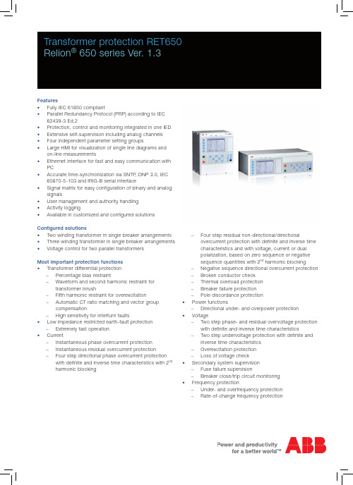
Transformer protection RET650 Relion® 650 series Ver. 1.3
Features • Fully IEC 61850 compliant • Parallel Redundancy Protocol (PRP) according to IEC
62439-3 Ed.2 • Protection, control and monitoring integrated in one IED • Extensive self-supervision including analog channels • Four independent parameter setting groups • Large HMI for visualization of single line diagrams and
LF356中文资料

LF355/356/357 JFET输入型运算放大器——中文数据手册--by LF邮箱:******************整体描述:这些是第一个合成的JFET输入的运算放大器,它把匹配的高电压的JFET晶体管和标准的双极性晶体管放到了一块芯片上(双极FET技术)。
这些运放的特征是低输入失调和偏置电流、低偏置电压和偏置电压漂移、可以进行偏置调节而不会降低漂移和共模抑制比。
这些运放也设计有高压摆率、宽带宽、极快的建立时间、低电压电流噪声。
特征:优点--代替昂贵的混合型和模块型FET运算放大器--低噪声应用性能优异——高或低的输入源阻抗均可--偏置可调不会像其他合成型运放降低漂移和共模抑制比--新的输出阶段可以接入大的电容负载(5000pF)不会出现稳定性问题--内部补偿和可承受大的差分输入电压应用:--精密高速积分器--快速模/数和数/模转换器--高阻抗缓冲保护--宽带、低噪、低漂移放大器--对数放大器--光电放大器--采样保持电路共同特性:--低输入失调电流——30pA--低输入偏置电流——3pA--高输入阻抗——10的12次方Ω--低输入噪声电流——0.01pA/sqrt(Hz)--高共模抑制比——100dB--高直流增益——106dB不同特性:--极快的建立时间——5系列4us,6系列7系列1.5us--快速的压摆率——5系列5V/us,6系列12V/us,7系列50V/us--宽增益带宽——5系列2.5MHz,6系列5MHz,7系列20MHz--低输入噪声电压——5系列20nV/sqrt(Hz),6系列7系列12nV/sqrt(Hz)供电电压:±15V典型电路连接:Vos调节--Vos用一个25k的电位器调节--电位器中间调节端连到V+驱动容性负载--对于LF155/6 R=5k--对于LF357 R=1.25k--由于独特的输出平台设计,这些放大器能够驱动大的容性负载并且能保持稳定性。
NS4205 3W双声道D类音频功放用户手册说明书

Nsiway
4
NS4205
3W双声道D类音频功放
1 功能说明
NS4205 是一款无需滤波器、D 类双声道音频功放。NS4205 采用先进的技术,在全带宽范围内极大 地降低了 EMI 干扰,最大限度地减少对其他部件的影响。NS4205 无需滤波器的 PWM 调制结构及反馈电 阻内置方式减少了外部元件、PCB 面积和系统成本。NS4205 内置过流保护、过热保护及欠压保护功能, 有效地保护芯片在异常工作状况下不被损坏。并且利用扩频技术充分优化全新电路设计,高达 90%的效 率更加适合便携式音频产品。
9 NS4205 应用说明............................................................................................................................................ 12
NS4205
3W双声道D类音频功放
NS4205 用户手册 V1.1
深圳市纳芯威科技有限公司 2012 年 02 月
Nsiway
1
日期
版本
作者
修改历史
NS4205
3W双声道D类音频功放
修改说明
Nsiway
2
NS4205
双声道D类音频功放
目录
1 功能说明 ........................................................................................................................................................... 5
计算机配置单
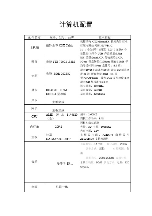
计算机配置
配件名称规格、型号、品牌技术指标
主机箱酷冷至尊CSX Celtic
机箱结构ATX/MicroATX 机箱类型:标准
标配电源:金河田355WB 3C
3.5寸仓位:两个软驱位5.25寸光驱:4个
前置接口:两个USB 产品质量:5.9kg
硬盘希捷1TB 7200.1132M 接口类型:Serial ATA 传输规范:SATA
3Gbps 硬盘转数:7200rpm 缓存:32MB 平均寻道时间:8.9ms 盘体尺寸:3.5英寸
光驱先锋BDR-202BK
最大DVD刻录速度:20速最大CD刻录速
度:48速缓存容量:2MB 接口类
型:ATAPI/EIDE 最大DVD复写速度:8速
最大CD复写速度:32速
显卡HD4850 512M
GDDR4至尊版核心频率:650MHZ 显存容量:512MB 显存频率:2200MHZ
声卡
主板集成
网卡
主板集成
CPU AMD 速龙11*4620
(盒)
频率:2.6GHZ
四核工作功率:95W
内存条2G*2 两根构成双通道
容量:2G 主频:800MHZ 内存电压:1.8V
主板技嘉
GA-MA7707-UD3P
主板芯片组:AMD770 南桥芯片
AMDSB710 支持双通道
音箱
漫步者S5.1音箱系统:5.1声道额定功率:280W 调节方式:遥控有源无源:有源
频率响应:20Hz-20KHz 音箱材质:木质信噪比:90dB 供电方式:电源:220 V/50Hz
电源机箱一体。
RF650中文资料
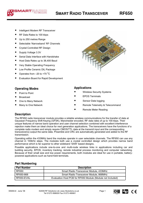
DS650-6 June ‘06©2006 RF Solutions Ltd, Page 1Tel 01273 898000 Fax 01273 480661S MART R ADIO T RANSCEIVER RF650ApplicationsWireless Security Systems 元器件交易网DS650-6 June ‘06©2006 RF Solutions Ltd, Page 2Tel 01273 898000 Fax 01273 480661S MART R ADIO T RANSCEIVER RF650Table Of Contents1 M o d u l e C o n n e c t i o n s ................................................................................................................3 2O p e r a t i o n .................................................................................................................................4 2.1 O p e r a t i o n M o d e s ..............................................................................................................4 2.2 S e r i a l D a t a F o r m a t ...........................................................................................................4 2.3 C T S t i m i n g .......................................................................................................................4 3 C o n f i g u r a t i o n ...........................................................................................................................5 3.1 S o f t w a r e C o n f i g u r a t i o n ....................................................................................................6 4 A p p l i c a t i o n I n f o r m a t i o n ............................................................................................................7 4.1 A p p l i c a t i o n S c h e m a t i c ......................................................................................................7 4.2 A n t e n n a D e s i g n ................................................................................................................8 5 T e c h n i c a l S p e c i f i c a t i o n s ..........................................................................................................9 5.1 M e c h a n i c a l D e t a i l .............................................................................................................9 6 E v a l u a t i o n B o a r d ...................................................................................................................10 6.1 C o n n e c t i o n s ...................................................................................................................10 6.2 M e c h a n i c a l D e t a i l s .........................................................................................................11 6.3 D I P S w i t c h C o n f i g u r a t i o n .. (11)元器件交易网DS650-6 June ‘06©2006 RF Solutions Ltd, Page 3Tel 01273 898000 Fax 01273 480661S MART R ADIO T RANSCEIVER RF650元器件交易网DS650-6 June ‘06©2006 RF Solutions Ltd, Page 4Tel 01273 898000 Fax 01273 480661S MART R ADIO T RANSCEIVER RF6502 OperationThe Host Data Rate pins are read when the PD pin goes high. The RF650 must be put into standby mode by taking the PD pin low in order to change the selection.The size of RF data packets are set during configuration. If fewer bytes are received by the RF650 than the preset size, then after 10ms from the last byte received from the host, the RF packet will be processed(expanded to meet the preset packet size) and transmitted. The RF data packet size must be set the same for transmitter and receiver, otherwise the received packets will be discarded.In order to optimise data rate , in a point-to-point configuration where data is mostly being sent in onedirection, the packet size for one data direction can be set to the maximum size, however the reverse direction may be set to a smaller packet size, to implement an acknowledge reply for example.The RTS pin overrides the timeout value. If a short data packet is sent, RF transmission will start as soon as the RTS pin is taken ‘high’ after the last byte is sent to the module.The RF650 contains an on-board data buffer equal to two data packets. Therefore if RTS is asserted (then the host is unable to receive data) the RF650 will store a max of two data packets, all further data packets received will be discarded.No RF packets will be received by the module when it is in power down standby mode.Each RF650 has its own preset address. This is set during configuration. Any data received is examined and the address header embedded within the data packet is compared with the RF60 address. Only data received with matching address will be processed and output to the host, all other data will be discarded. All RF650 modules are shipped with a default address of 7E7E7E7E.2.1 Operation ModesThe addressing protocol employed enables many different configurations such including: one-to-one operation; for point to point data communicationbroadcast operation; where a single master address many RF650 modules concurrently. (using many RF650 modules set to the same address),one-to-many ; A network consisting a master and many slaves (the receivers all have the same address) many-to-one; where the transmitters all send to a single receiver address.Because each RF650 can contain a unique address, multiple RF650 networks can co-exist in the same area.2.2 Serial Data FormatThe RF650 serial format settings are:Baud Rate: Defined by DR1 and DR2 Pins Data Bits: 8Parity: None Stop Bits: 1Flow Control: Hardware2.3 CTS timingWith a standard buffer size of 30 bytes, CTS is asserted 41uS after the buffer is full. In cases where less than 20 bytes are sent CTS is asserted after a timeout of 10mS.元器件交易网DS650-6 June ‘06©2006 RF Solutions Ltd, Page 5Tel 01273 898000 Fax 01273 480661S MART R ADIO T RANSCEIVER RF650元器件交易网DS650-6 June ‘06©2006 RF Solutions Ltd, Page 6Tel 01273 898000 Fax 01273 480661S MART R ADIO T RANSCEIVER RF650Figure 1. Configuration register not readFigure 2. Configuration register read / written元器件交易网DS650-6 June ‘06©2006 RF Solutions Ltd, Page 7Tel 01273 898000 Fax 01273 480661S MART R ADIO T RANSCEIVER RF650Circuit notes:J2,3,4 and 5 allow the selection of the following modes:J2 when shorted sets the module for normal running mode or if left open selects configuration mode. J3 and J4 selects the host data rate.J5 when sorted puts the module into standby mode or when left open in normal operation.If two such circuits are constructed then it will be possible to interconnect two PC’s and test out theperformance of the hybrids. When both circuits are powered up it will be necessary for them to have each others address in the “Destination Address” register.元器件交易网DS650-6 June ‘06©2006 RF Solutions Ltd, Page 8Tel 01273 898000 Fax 01273 480661S MART R ADIO T RANSCEIVER RF650元器件交易网DS650-6 June ‘06©2006 RF Solutions Ltd, Page 9Tel 01273 898000 Fax 01273 480661S MART R ADIO T RANSCEIVER RF650元器件交易网DS650-6 June ‘06©2006 RF Solutions Ltd, Page 10Tel 01273 898000 Fax 01273 480661S MART R ADIO T RANSCEIVER RF650元器件交易网DS650-6 June ‘06©2006 RF Solutions Ltd, Page 11Tel 01273 898000 Fax 01273 480661S MART R ADIO T RANSCEIVER RF650元器件交易网。
SilverStone Zeus ST65ZF 650W 电源说明书
01SPECIFICATIONSilverStone Zeus ST65ZF active PFC power supplyThis specification describes the requirements of 650Watts switching power supply with an stretch form-factor and EPS12V , +5V standby voltage, remote on/offcontrol, dual line input capability and forced air cooling characteristics .1. AC INPUT1.1 AC input requirementsThe input voltage, current, and frequency requirements for continuous operation are stated below.Power factor correction (PF)>0.95 at full loadTable 1 AC Input Line Requirements1.2 Inrush current regulation50 A @ 115Vrms100 A @ 230Vrms (at 258C ambient cold start)ZEUS ST65ZF2. DC OUTPUT2.1 DC voltage regulation2.2 Load ranges2.2.1 : (650 Watts Load Ratings-Dual +12V Rails for processor Power)Load Range 102Load Range 2Notes:(1) The maximum continuous total DC outputs power shall not exceed 650W(2) The maximum continuous load on +5V and +3.3V outputs shall not exceed 170W.(5) The maximum combined current for the +12V outputs shall be 42A, peak load 45A(6) The 5V standby output shall remain on while the AC input power connected, whether DCoutputs are disabled (Off) or enabled (On) by the remote on control signal, but when the 5VStandby output remained on with the AC input power turn off, the remote on control will bedisabled.(7) The total peak load is 710W for 10 second.2.3 Output Ripple2.3.1 Ripple regulation2.3.2 DefinitionThe ripple voltage of the outputs shall be measured at the pins of the output connectorwhen terminated in the load impedance specified in figure 1. Ripple and noise are measuredat the connectors with a 0.1uF ceramic capacitor and a 10uF electrolytic capacitor tosimulate system loading. Ripple shall be measured under any condition of line voltage,output load, line frequency, operation temperature.03ZEUS ST65ZF2.3.3 Ripple voltage test circuitFigure 1. Ripple voltage test circuit2.4 OvershootAny overshoot at turn on or turn off shall be less 10% of the normal voltage value, alloutputs shall be within the regulation limit of section 2.0 before issuing the power goodsignal of section 5.02.5 Efficiency75.8% maximum2.6 Remote ON/OFF controlWhen the logic level "PS-ON" is low, the DC outputs are to be enabled.When the logic level is high or open collector, the DC outputs are to be disabled.043. PROTECTION3.1 Over current protectThe power supply shall have current limit to prevent the +3.3V, +5V, and +12V1,+12V2,+12V3 outputs from exceeding the values shown in the following Table. If thecurrent limits are exceeded the power supply shall shutdown and latch off.Dual +12V for processor (650W)3.2 Under voltage protection.In an under voltage fault occurs, the supply will latch all DC outputs into a shutdown statewhen +5V & +3.3V outputs under 85% of its maximum value.3.3 Over voltage protectionThe over voltage sense circuitry and reference shall reside in packages that are separateand distinct from the regulator control circuitry and reference. No single point fault shallbe able to cause a sustained over voltage condition on any or all outputs. The supply shallprovide latch-mode over voltage protection as defined in Table.3.4 Short circuitAn output short circuit is defined as any output impedance of less than 0.1 ohms. The powersupply shall shut down and latch off for shorting the +3.3 VDC, +5 VDC,or+12 VDC railsto return or any other rail. Shorts between main output rails and +5VSB shall not cause anydamage to the power supply. The power supply shall either shut down and latch off or foldback for shorting the negative rails.+5VSB must be capable of being shorted indefinitely,but when the short is removed, the power supply shall recover automatically or by cyclingPS_ON#. The power supply shall be capable of withstanding a continuous short-circuit tothe output without damage or overstress to the unit05ZEUS ST65ZF3.5 No load operationNo damage or hazardous condition should occur with all the DC output connectors disconnected from the load. The power supply may latch into the shutdown state.4. TIMING4.1 Signal timing drawingFigure 2. is a reference for signal timing for main power connector signals and railsFigure 2. PS-OK Timing Sequence(1) T2: Rise time (0.1ms~70ms)(2) T3: Power good signal turn on delay time (100ms~1000ms)(3) T4: Power good signal turn off delay time (1ms min)(4) T5: Rise time (10ms max)(5) T6: Hold up time (17ms min)4.2 Hold up timeWhen the power loss its input power, it shall maintain 17ms in regulation limit at normal input voltage (AC:115V/60Hz or 230V/50Hz)5. ENVIRONMENT5.1 Operation5.2 Shipping and Storage06VACPS-ON+12V/+5V/+3.3V O/Ppw-OKnominal5.3 Altitude6. SAFETY6.1 Underwriters Laboratory (UL) recognition..The power supply designed to meet UL 1950.6.2 The power supply must bear the German Bauart Mark from TUV.7. ELECTROMAGNETIC COMPATIBILITY (EMC)7.1 IEC 1000-4-2 ESD LEVEL X20KV4.7.2 IEC 1000-4-3 radiated electrical field requirement.7.3 IEC 1000-4-4 BURST7.4 IEC 1000-4-5 surge Voltages7.5 EN61000-3-2 harmonic current emissions.If applicable to sales in Japan or Europe, the power supply shall meet the requirements ofEN 61000-3-2 class D and the guidelines for the suppression of harmonics in appliances andgeneral use equipment class D for harmonic line current content at full-rated power.7.6 EN55024 class B radio interference (CISPR 22)7.7 FCC part 15, subpart J class B 115V AC operation.8. MTBF8.1 MTBF (mean time between failures) calculationThe demonstrated MTBF shall be 100,000 hours of continuous operation at 258C, full load,80% confidence limit and nominal line. The MTBF of the power supply be calculated inaccordance with MIL-HDBK-217F. The DC FAN is not included.9. MECHANICAL REQUIREMENTS9.1 Physical dimension150 x 86 x 180 mm (W x H x D)9.2 Net weight2.7 kg07ZEUS ST65ZF9.3 Connectors & cable length9.3 Pin definitionM/B 24PIN connector081 & 23 & 409ZEUS ST65ZF 20885 Currier RoadCity of Industry , CA 91789Tel: 909-598-2318Fax: 909-598-2518alex10。
2.7W双声道立体音频放大器
2.7W双声道立体音频放大器概述4985SD是一款双通道桥接的音频功率放大器,在5V电源电压4Ω负载时,可提供2.7W的功率。
具有低功耗关断模式和过温保护功能。
在电路启动时,具有缓冲及防抖动功能。
功能特点l缓冲及防抖动l过温保护l低功耗关断模式l PO为1% THD+N, VDD = 5VRL=4Ω 2.2W(typ)RL=8Ω 1.4W(typ)l PO为10% THD+N, VDD = 5VRL=4Ω 2.7W(typ)RL=8Ω 1.7W(typ)l PO为1% THD+N, VDD = 4VRL=4Ω 1.4W(typ)RL=8Ω0.88W(typ)l关断电流0.04μA(typ)l工作电压范围 2.7V~5.5Vl封装方式:DIP16(4985SD)用途l手机、PDA、MP4、PMPl手提电脑l桌面音响设备l多媒体显示器管脚排列图管脚说明功能框图功能说明桥接参数说明4985SD由两对运算放大器组成双通道(通道A和通道B)立体声放大器。
外接反馈电阻R2,R4和输入电阻R1,R3决定了放大器A(-out)和B(-out)的闭环增益,同时内建20K电阻使放大器A的(+out)和B的(-out)端的增益为1。
4985SD所驱动的负载接在两放大器的输出端-OUTA和+OUTA之间。
放大器A的(-out)端就是放大器A的(+out)端的输入端,这就使两个输出端产生的信号有180°的相位差,利用这个相位差,桥接模式下的增益为:A VD=2*(Rf/Ri)或者A VD=2*(R2/R1)桥接模式比单端模式更有优势。
在桥接模式下,差分输出使增益翻倍,它的输出功率是相同情况下单端模式的4倍。
桥接模式的另一个优势是在负载上没有直流电压。
输出信号由通道A和B偏置在VDD/2。
所以它无需在单端模式下的耦合电容。
在单端输出模式下,如果不使用输出耦合电容,就会在负载上产生一个VDD/2的直流偏置电压,这就会增加芯片的功耗并对负载造成永久性的损害。
650型石墨精雕机参数

XTH-M650S数控石墨精雕机一、技术参数名称单位参数X/Y/Z三轴行程mm 500/600/250工作台面积mm2600*500工作台负重kg 250主轴端面至工作台装卡高度mm 50-300 弹簧夹头# ER25 刀具最大夹持直径mm 16 最大移动速度mm 10000最大加工速度mm 8000定位精度mm 0.005/300重复定位精度mm 0.003/300主轴功率kw 5.5主轴最大转速rpm 24000电源总功率kw 8.5电源电压v 380机床外形尺寸(长/宽/高) mm 2050/1980/2400 机床最大总重量kg 3000二、标准配置1.控制系统:台湾新代21MA控制系统2.三轴驱动电机:日本安川伺服电机3.主轴:5.5KW主轴4.台湾上银或银泰C3精密滚珠丝杆及上银H级导轨5.日本NSK轴承6.油冷恒温热交换系统7.高强度全铸铁床身8.电箱与控制器一体化设计9.全封闭式钣金,豪华钣金10. 抽油马达11. LED工作灯12. 容积式注油器13. X/Y轴防护罩(Y轴前后不锈钢护罩)14. 全自动对刀仪,刀具长度自动补偿15. 润滑系统采用8号机油自动润滑16. 手持式电子手轮17. 石墨机专用立体全封闭风琴罩(双层防护)18. 全面优化的机身排渣系统19. 专业石墨粉尘集尘器(干式石墨精雕机配备)三、附赠配件1. 多功能工具箱2. 操作系统说明书3. 随机赠送5只弹簧夹头(3¢4¢6¢8¢10¢12)声明1.由于本公司不断改进产品,因此本公司保留随时更改设计及规格和配置的权利且不另行通知,如蒙惠顾,请确认规格是否变更。
2.整机免费保修一年(赠送配件不在保修范围内,人为或天灾等因素损坏亦须酌情收取相应维修费用),请勿自行维修和更换零件,否则供方无法提供维修。
ARS35中文资料

ARS
AR
Mechanical Data
Case: Molded plastic case Terminals: Plated terminals, solderable per MILSTD-202, Method 208 Polarity: Color ring denotes cathode end Weight: 0.07 ounce, 1.8 grams Mounting position: Any
FIG.2- MAXIMUM NON-REPETITIVE PEAK FORWARD SURGE CURRENT
PEAK FORWARD SURGE CURRENT. (A)
8.3ms Single Half Sine Wave JEDEC Method 500
AVERAGE FORWARD CURRENT. (A)
- 502 -
元器件交易网
RATINGS AND CHARACTERISTIC CURVES (ARS35 THRU AR35)
FIG.1- MAXIMUM FORWARD CURRENT DERATING CURVE
35 1000 SINGLE PHASE HALF WAVE 60Hz RESISTIVE OR INDUCTIVE LOAD
Operating and Storage Temperature Range
TJ, TSTG -50 to +175 Notes: 1. Measured at 1 MHz and Applied Reverse Voltage of 4.0 V D.C. 2. Reverse Recovery Test Conditions: IF=0.5A, IR=1.0A, IRR=0.25A 3. Thermal Resistance from Junction to Case, Singe Side Cooled.
- 1、下载文档前请自行甄别文档内容的完整性,平台不提供额外的编辑、内容补充、找答案等附加服务。
- 2、"仅部分预览"的文档,不可在线预览部分如存在完整性等问题,可反馈申请退款(可完整预览的文档不适用该条件!)。
- 3、如文档侵犯您的权益,请联系客服反馈,我们会尽快为您处理(人工客服工作时间:9:00-18:30)。
Littelfuse now offers a complete selection of “E”and “R”rated medium voltage fuses for the protection of trans-formers, potential transformers, feeders, and motor circuits.Single, double, and triple barrel designs are available to cover a wide range of current, voltage, and interrupting ratings.Conventional ferrule type, clip lock, and bolt-in mounting configurations are now available for virtually any application.Hermetically sealed fuses for use in hazardous environments are also offered.
Contact the factory or your local Littelfuse representative for additional fuse ratings or custom mounting configurations.24 Hour Emergency Service is available.Call 1-800-227-0029.
APPLICATIONS
s
Power T ransformer Protection
s
Potential T ransformer Protection
s
Motor Controller Back-up Protection
s Fused Switches s
Feeder Circuits
GENERAL INFORMATION
The terms “Medium Voltage”and “high voltage”have been used interchangeably by many people to describe fuses operating above 600 volts.T echnically speaking, “medium voltage”fuses are those intended for the voltage range from 2,400 to 38,000 VAC.“High voltage fuses are for circuits carrying voltages greater than 38,000 VAC.
“E”Rated fuses are considered to be general purpose fuses and can be used to protect against low and high values of fault current.“R”rated fuses are designed for back-up pro-tection.They must be used in series with other devices, such as motor overload relays, in order to achieve both overload and short circuit protection.
Medium voltage fuses are not intended to provide overload protection in the same sense as fuses rated 600 volts or less.Medium voltage fuse current ratings do not have the same meanings as the ampere ratings of low voltage fuses.All medium voltage fuses are limited in their ability to inter-rupt low value overcurrents, especially those between 100%and 200% of the fuse’s continuous current rating.They are designed to carry their rated current without exceeding the temperature rise permitted by NEMA and ANSI standards.Additional application data can be found in the Fuse Application section of the POWR-GARD Products catalog (PF101).
Current limiting “E”and “R”rated fuses are equipped with a mechanical indicator or striker pin that protrudes through the fuse cap upon operation of the fuse.This provides visual identification of a blown fuse and can be used as a trigger for external devices.
Bolt-in Mount Fuses
15,500 volts
Hermitically sealed for use in hazardous locations
suffix to part number)
FIGURE 4FIGURE 5FIGURE 6
Add “w ”suffix to part number for hookeye attachment .
Bolt-In Mount “BI”
FIGURE 11
FIGURE 12
FIGURE 13
71
Potential T ransformer (PT) fuses are current limiting fuses with high interrupting ratings designed for the protection of potential transformers.
Application Note:
When applying fuses for the protection of transformers, the magnetizing current inrush must be considered.The characteristics of the inrush, which can be matched with a fuse ’s time-current curve, should be available from the transformer manufacturer.
”,
Mounting clips are available 72。
