GF1B中文资料
SLPB-1L-B;SLPB-1L-W;SLPB-2M-B;SLPB-2M-W;SLPB-3M-B;中文规格书,Datasheet资料

SLPB-1S ~ SLPB-2S
NOTES: 1. PLUNGER MATERIAL: NYLON 6, (RMS-120). SLPB-2M MATERIAL: NYLON 6 (RMS-52) 2. GROMMET MATERIAL: POLYCARBONATE, (RMS-72). 3. COLOR: BLACK OR WHITE; ADD SUFFIX "-B" OR "-W" TO PART NO.
.425 [10.8] .335 [8.5] .256 [6.5]
.079 [2] .071 [1.8] .04.2] .295-.303 [7.5-7.7] .315-.323 [8-8.2] .118-.205 [3-5.2] .059-.146 [1.5-3.7] .079-.165 [2-4.2] .234-.240 [5.95-6.1] .250-.256 [6.35-6.5] .118-.272 [3-5.2] .079-.158 [2-4] .177-.181 [4.5-4.6] .185-.189 [4.7-4.8] .098-.177 [2.5-4.5]
SEE TABLE
PRINT TYPE
(773) 539-4060
CA
分销商库存信息:
RICHCO-INC SLPB-1L-B SLPB-2M-W SLPL-1L-B SLG-1L-W SLG-3M-B SLG-2L-W SLPB-1L-W SLPB-3M-B SLPL-1L-W SLG-2M-B SLG-3M-W SLPL-2L-B SLPB-2M-B SLPB-3M-W SLG-1L-B SLG-2M-W SLG-2L-B SLPL-2L-W
/
GF1抗磨剂

GF1强力抗磨金属调理剂等,它是美国太空总署(NASA)“零故障太空机械操作计划试验室”的机械润滑专家基于零磨损的理念,采取磁性离子激活化学技术、纳米技术发明的不含金属及任何添加物质的高浓缩、纯油、特耐磨金属表面调理剂。
Antifriction Metal Conditioner是美国西方石油公司技术成果产品。
它利用热激活化学技术,借助润滑油、润滑脂或润滑剂作为载体加入到运转设备当中。
在各种机械传动摩擦运动中,随着温度升高,其离子态金属有机物和化合物被激活,其含有的金属离子变成了运动副材料表面分子结构的一部分,改变原金属的分子状态,从而填补了金属空隙,并且与金属紧密结合,产生一种表面保护膜,使金属表面平滑、坚硬,摩擦力大为降低。
该产品不含任何金属成份或固体润滑剂、树脂,使用后无胶状物和杂质产生,没有任何副作用,耐高温、高压,抗腐蚀,对人体和环境完全无害。
它是以油为载体在接触的液体和金属分子之间进行迅速的离子交换,以修补金属内质。
极化作用是半永久性地导致有机金属的保护层的形成,尤其能被磨损处或设计缺陷引起的热点吸引,极热的工作表面,如齿轮分界面、涡轮增压器的主要轴承、气门、气门轴和活塞环是最能吸引的地方。
GF1金属表面调理剂凭借应用范围广、质量性质稳定、没有副作用、节约能源及降低成本的优势,很快在市场竞争中占据主导地位。
1997年9月由Precious Shell Group引进中国,经过胜利油田、上海宝钢等用户试验、应用验证,GF1是具有世界领先水平的特耐磨金属表面改质处理剂。
2000年10月被中国国际环保节能协会列入第一批环保节能项目产品推广应用,已广泛应用于石油、化工、煤炭、电力、冶金、机械、医药、运输、军事动力机械装备等几乎所有存在摩擦的领域。
该产品的最初目的,是为了减少或降低因高速旋转和运动给高性能、高精度机械设备带来的磨损。
由于人们没有足够重视磨擦和磨损,经常会带来最大的经济损失。
磨损降低了运行效率,并造成能量损失、燃料增加和油量的耗费,导致了操作养护上的费用增高。
GBU1B中文资料

Non-Repetitive Surge Current
PEAK FORWARD SURGE CURRENT (A) 100 50
ACEx™ Bottomless™ CoolFET™ CROSSVOLT™ E2CMOSTM FACT™ FACT Quiet Series™ FAST FASTr™ GTO™
DISCLAIMER
HiSeC™ ISOPLANAR™ MICROWIRE™ POP™ PowerTrench QFET™ QS™ Quiet Series™ SuperSOT™-3 SuperSOT™-6
TA = 25°C unless otherwise noted
Device
1B 100 70 100 1D 200 140 200 1G 400 280 400 5.0 50 1.0 2.0 15 1.2 1J 600 420 600 1K 800 560 800 1M 1000 800 1000
1
TA = 75º C
1
0.1
0.1
TA = 25 º C Pulse Width = 300µS 2% Duty Cycle
0.01
TA = 25º C
0.01 0.4
0.6
0.8 1 1.2 1.4 1.6 FORWARD VOLTAGE (V)
1.8
2
0.001
0 20 40 60 80 100 120 140 PERCENT OF RATED PEAK REVERSE VOLTAGE (%)
ASMEB中文版
ASMEB中文版美国国家标准管螺纹通用标准(单位:英寸)ANSI/ASME B1.20.1 - 1983(根据ANSI 82.1-1968版修订并重新制定)1992年重审通用委员会专用请参阅ASME手册(美国机械工程师协会手册) AS-112001年重审通用委员会专用2006年重审通用委员会专用美国机械工程师学会赞助出版地址:联合工程中心345东47街纽约州,N.Y邮编:10017验收通知本文件为非政府文件,于1984年10月25日通过并由联邦机构核准使用。
这里显示产业集团提供了通关所需要的现行法规。
该文件的副本由国防部标准化资料管理中心、海军出版物和位于PA 19120费城的表格中心收藏,正式版本的发行仅用于国防部活动。
承包商和产业集团必须直接从以下机构获得副本:美国机械工程师学会(345东47街纽约10017-345 East 47th Street New York, New York 10017)或美国国家标准学会(1430百老汇纽约10018-1430 Broadway New York, New York 10018)。
文件名称:通用管螺纹(英寸)具体发布时间:1983年4月发布单位:美国机械工程师学会注意事项:联邦机构使用本标准时,须遵循联邦事务第7条螺纹标准FED-STD-H28/7中通用管螺纹的所有要求和限制。
注意事项:当对本标准的重申,修订,修改或取消最初提出时,工业集团应为本标准负责,并通知军方协调活动或通知被提议的变更,并要求其参与。
管理者:民间机构间的协调活动:陆军-AR 商业-国家商务部审查—FPI海军-AS 运输部—ACO, APM, FAA, FRA, NHT空军-11 NASA(国家航空和宇宙航天局)—JFK, LRC, MSF总务管理局—FSS,PCD 美国农业部—AFS住房和城市发展部—HCC评审活动:海军-YD 陆军-AT, GL, ME, MI军事协调活动:国防后勤局-IS (工程THDS-0052)发行日期:1983年8月31日本守则或标准是按公认程序进行开发的,符合美国国家标准。
gf1b 辐射定标

gf1b 辐射定标
摘要:
1.辐射定标的概念和意义
2.辐射定标的方法
3.辐射定标的应用
4.辐射定标的发展趋势
正文:
辐射定标是遥感技术中的一项重要工作,它主要是通过在地面上设立一些标志物,然后通过遥感器对这些标志物进行观测,从而确定遥感图像的辐射值。
这样一来,就可以将遥感图像的辐射值转化为实际的地面反射率,从而更准确地反映出地面的真实情况。
辐射定标的方法主要有两种,一种是基于模型的定标方法,另一种是基于数据的定标方法。
基于模型的定标方法是通过建立遥感图像辐射值和地面反射率之间的模型,从而实现辐射值的定标。
而基于数据的定标方法则是通过大量的已定标的地面数据,建立遥感图像辐射值和地面反射率之间的对应关系,从而实现辐射值的定标。
辐射定标在遥感技术中有着广泛的应用,它可以用于气象、环境监测、城市规划等领域。
例如,在气象领域,通过辐射定标,可以更准确地获取云层、大气等的辐射信息,从而提高天气预报的准确度。
随着遥感技术的发展,辐射定标的技术也在不断进步。
G1B中文资料
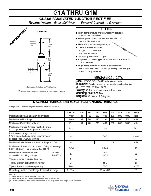
G1A THRU G1MGLASS PASSIVATED JUNCTION RECTIFIERReverse Voltage - 50 to 1000 Volts Forward Current - 1.0 AmpereFEATURES♦High temperature metallurgically bonded constructed rectifiers♦ Glass passivated cavity-free junction in D0-204AP package♦ Hermetically sealed package ♦ 1.0 ampere operation at T A =100°C with no thermal runaway♦ T ypical I R less than 0.1µA♦ Capable of meeting environmental standards of MIL-S-19500♦ High temperature soldering guaranteed:350°C/10 seconds, 0.375" (9.5mm) lead length,5 lbs.(2.3kg) tensionMECHANICAL DATACase:JEDEC DO-204AP solid glass bodyTerminals:Solder plated axial leads, solderable per MIL-STD-750, Method 2026Polarity:Color band denotes cathode end Mounting Position:AnyWeight:0.02 ounce, 0.56 gramMAXIMUM RATINGS AND ELECTRICAL CHARACTERISTICSRatings at 25°C ambient temperature unless otherwise specified.SYMBOLS G1A G1B G1D G1G G1J G1K G1M UNITSMaximum repetitive peak reverse voltage V RRM 501002004006008001000Volts Maximum RMS voltage V RMS 3570140280420560700Volts Maximum DC blocking voltageV DC 50702004006008001000Volts Maximum average forward rectified current 0.375” (9.5mm) lead length at T A =100°C I (AV) 1.0Amp Peak forward surge current8.3ms single half sine-wave superimposed on rated load (JEDEC Method)I FSM 50.0AmpsMaximum instantaneous forward voltage at 1.0A V F 1.21.1Volts Maximum full load reverse current, full cycle average 0.375” (9.5mm) lead length at T A=100°C I R(AV)200.0µA Maximum DC reverse current T A =25°C 2.0at rated DC blocking voltage T A =150°CI R 100.0µA Typical reverse recovery time (NOTE 1)t rr 1.5µs Typical junction capacitance (NOTE 2)C J 15.0pF Typical thermal resistance (NOTE 3)R ΘJL 55.0°C/W Operating junction and storage temperature rangeT J , T STG65 to +175°CNOTES:(1) Measured with I F =0.5A, I R =1.0A, I rr =0.25A(2) Measured at 1.0 MH Z and applied reverse voltage of 4.0 Volts(3) Thermal resistance from junction to ambient at 0.375" (9.5mm) lead length P.C.B. mounted4/98Dimensions in inches and (millimeters)*Brazed-lead assembly is covered by Patent No.3,930,306P A TE NT ED*DO-204AP02550751001251501750.20.40.60.81.01101001020304050110100110300.40.60.8 1.0 1.2 1.4 1.60.010.1110204060801000.010.1110RATINGS AND CHARACTERISTIC CURVES G1A AND G1MFIG. 1 - FORWARD CURRENT DERATING CURVEFIG. 3 - TYPICAL INSTANTANEOUS FORWARD CHARACTERISTICSFIG. 4 - TYPICAL REVERSE CHARACTERISTICS60 H ZRESISTIVE OR INDUCTIVE LOADPULSE WIDTH=300µs 1% DUTY CYCLET J =25°CT J =125°CT J =75°CAMBIENT TEMPERATURE, °CNUMBER OF CYCLES AT 60 H ZPERCENT OF RATED PEAK REVERSE VOLTAGE, %A V E R A G E F O R W A R D R E C T I F I E D C U R R E N T , A M P E R E SFIG. 2 - MAXIMUM NON-REPETITIVE PEAKFORWARD SURGE CURRENTI N S T A N T A N E O U S R E V E R S E C U R R E N T ,M I C R O A M P E R E SINSTANTANEOUS FORWARD VOLTAGE,VOLTSFIG. 5 - TYPICAL JUNCTION CAPACITANCEREVERSE VOLTAGE, VOLTSP E A K F O R W A R D S U R G E C U R R E N T ,A M P E R E SJ U N C T I O N C A P A C I T A N C E , p FI N S T A N T A N E O U S F O R W A R D C U R R E N T ,A M P E R E ST J =T J max.8.3ms SINGLE HALFSINE-WAVE(JEDEC Method)T J =25°C f=1.0 MHz Vsig=50mVp-p0.375" (9.5mm) LEAD LENGTHCAPACITANCE LOAD Ipk/I AV = 5.01020T J =25°CT J =150°C。
GF1B、C、D星数据质量在轨测试评价研究

762.76
657.94
407.12
4
1155.15
1050.34
574.81
715.57
pan 105.406615
888.13
539.67
421.49
1
0.38
1.34
3.51
4.74
2
0.50
1.18
2.42
4.08
信噪比 3
0.50
0.90
1.31
2.74
4
0.45
1.31
3.60
2.43
pan
46
L 国土资源 AND&RESOURCES
数字自然
源 资
SHUZIZIRANZIYUAN
表1 GF-1B、C、D卫星影像灰度特征对比表
统计值 波段
GF-1A
研究区影像
GF-1B
GF-1C
GF-1D
1
25-1009
0-4145
0-4095
0-4352
2
灰度动态 范围
3
4
323-1023 18-1023 22-1023
4.34
1.24
2.97
3.64
1 0.0000018464
0
0.0000000130 0.0000000059
2 0.0000011550 0.0000000012 0.0000000140 0.0000000116
偏斜度 3 0.0000010445 0.0000000056 0.0000000120 0.0000000234
(3)制图效率评价 主要从以下几方面进行评价。 ①首先进行波段配准,控制点 从 10 开始逐渐递增,分别记录 GF1B、C、D 星 2A 级产品与基础底图 数据波段匹配结果满足 1 ∶ 5 万影 像图制图规范时所需的控制点数, 同时对不同控制点规模下波段匹配 精度进行分析。 ② 在完成波段配准后,通过参 考影像匹配或控制点库匹配的方式, 分别对 GF-1B、C、D 星和国内外其 它高分卫星数据获取一系列校正控 制点,使用逐渐递增的控制点规模, 结合 DEM 数据,开展正射校正,分 别记录正射校正后影像满足 1 ∶ 5 万制图规范时,所对应的控制点数。 ③ GF-1B、C、D 星数据处理工 作时间效率的统计评价。
112B中文资料

Previous Page | Return to Index | Next Page1/4" ENCLOSED PHONE JACKS1. Series 11*2. PC Terminal View*3. Series N11*click here to download a schematic drawing(you will need to have Adobe Acrobat installed on your system to do this)Hi-D® Jax 2- and 3-CONDUCTORHi-D Jax® 2- and 3-conductor enclosed phone jacks are ideal for panel/chassis and PC board mounting. Unitized molded housing protects springs, provides mechanical and electrical reliability, minimizes leakage and provides low capacity between springs. Mounts on .625 inch minimum centers in rows or arrays. .25 inch or .21 in inside diameter bushing types, metal or thermoplastic bushings (for insulated mounting). Insulated Hi-D Jax® jacks are specifically designed for in-circuit (insulated) mounting from mounting surface and have fully protected enclosed internal sleeve feature. Solder lugs or PC terminals may be selected.MOUNTINGJacks mount in a single .375 inch diameter hole on .625 inch minimum centers. Series11*, N11*, NS11* and S11* mount in panels up to .156 inch thick. Series L11* andNL11* (long bushing) mount in panels up to .25 inch thick. Jacks with PC terminals mount on PC boards up to .094 inch thick. Formed "shoulders" on each terminal provide stable stand-off mount. Threaded bushing permits mechanical connection to equipment panel. Mounting hardware is supplied.SERIES 11* - 2- and 3-conductor types, threaded metalbushing .276 inch long. .25 inch inside diameterbushings.SERIES L11* - Same as Series 11*, except bushing is .375inch long for mounting in panels up to .25 inch thick.SERIES N11* - Same as Series 11*, except bushing ismolded thermoplastic for insulated mounting.SERIES NL11* - Same as Series N11*, except bushingis .375 inch long for insulated mounting in panels up to.25 inch thick.SERIES S11* - Same as Series 11*, except bushing has.21 inch inside diameter. Smaller diameter protects againstaccidental insertion of plugs with .25 inch diameter fingers.ý NS11* - (SPECIAL ORDER ONLY) - Same asSeries N11*, except bushing is .21 inch inside diameter.113BPC1M AND 114BPC1M - Versatile, 3-conductor 113BPC1M and 114BPC1M feature springs which accept a wide variety of 1/4 inch plug designs. Self-aligning PC terminals allow for easier insertion into a printed circuit board. Also feature a metric thread mounting.TWO CONDUCTOR PART NUMBERSSolder Lug Part Number PC TerminalsPart NumberDescription Jack Schematic1TypicalMating Plug2111111PC Open circuit I250 N111N111PC Insulated bushing I250NL111-.375 " long insulatedbushingI250112A112APC Single closed circuit III250 L112A L112APC.375" long bushing III250 N112A N112APC Insulated bushing III250NL112A-.375" long insulatedbushingIII250113113PC Isolated "make" circuit V250 N113-Insulated bushing V250ý 113D113DPC Transfer circuit (1-C)VI 3250 113E113EPC Isolated "break" circuit IX250 THREE CONDUCTOR PART NUMBERS112B112BPC Double open circuit IV267L112B-.375" long bushing IV267 N112B N112BPC Insulated bushing IV267 NL112B-.375" long bushing IV267-S112BPC .210" inside diameterbushingIV S-267113B113BPC Single closed circuit VII267-113BPC1M Single closed circuit VII-L113B-.375" long bushing VII267 N113B N113BPC Insulated bushing VII267 NL113B-.375" long bushing VII267 113F113FPC Ring circuit closed XXVIII267 114B114BPC Double closed circuit XII267 114BPC1M Double closed circuit XII-L114B L114BPC.375" long bushing XII267 N114B N114BPC Insulated bushing XII267 NL114B NL114BPC.375" long bushing XII2671 Other circuits available; contact factory. Schematics pages 65 and 66.2 See Plug Section for other options.3 Two tip springs.ý Special order only. Contact Switchcraft.SPECIFYING NOTE:Unless otherwise shown in "Description", jacks have .276 inch long threaded bushings with .25 inch inside diameter.Hi-D Jax® 2- and 3-CONDUCTORSPECIFICATIONSMATERIALMounting Bushing: Series 11*, L11*, S11* - Nickel-plated copper alloy. Series N11*, NL11*, NS11* - Molded thermoplastic over nickel-plated copper alloy sleeve.Previous Page | Return to Index | Next PageTo search a category please click on the corresponding icon:| Connectors | Jacks and Plugs || Patch Panels, Patch Kits & Jackfields | Cable Assemblies and Patch Cords | Switches | All products shown are covered by Switchcraft's limited lifetime warranty.| Switchcraft home |About Us | Products | What's New | Search | Contact Us。
ZL01B Wireless-Combined Interface说明书

型号:ZL01BWireless-Combined InterfaceCombined Interface说明书适用Firmware:V4.7适用Hardware:V1.3目录一、声明 (2)二、实物外观 (3)三、简介 (4)四、产品特性 (4)五、操作说明 (4)1.加网 (4)2.传输模式说明 (4)3.管理与控制(Gateway模式) (5)4.允许加网 (8)5.恢复出厂设置 (8)6.ZigBee描述 (8)六、与奈伯思系统APP配合使用 (9)七、安装方法 (13)八、维护与保养 (16)一、声明在未经大洋事先书面许可的情况下,严禁以任何形式复制、传递、分发和存储本文档中的任何内容。
大洋遵循持续发展的策略。
因此,大洋保留在不预先通知的情况下,对本文档中描述的任何产品进行修改和改进的权利。
在任何情况下,大洋均不对任何数据或收入方面的损失,或任何特殊、偶然、附带或间接损失承担责任,无论该损失由何种原因引起。
本文档的内容按“现状”提供。
除非适用的法律另有规定,否则不对本文档的准确性、可靠性和内容做出任何类型的、明确或默许的保证,其中包括但不限于对适销性和对具体用途的适用性的保证。
大洋保留在不预先通知的情况下随时修订或收回本文档的权利。
二、实物外观GNDRS485-ARS485-B允许加网键USB电源接口网络状态灯三、简介ZL01B在网络中作为路由设备(Router Device)或协调器(Coordinator Device)使用,允许其他设备做为其子设备。
具有两种通信功能,一种:资料传输,使用终端设备连接ZL01B可发送任意数据到空中;一种:命令传输,配合使用上位机软件,可经网络中的设备搜索回来。
ZigBee无线技术:ZigBee是一种新兴的近距离、低复杂度、低功耗、低数据速率、低成本的无线网络技术,它是一种介于无线标记技术和蓝牙之间的技术提案。
主要用于近距离无线连接。
它依据802.15.4标准,在数千个微小的传感器之间相互协调实现通信。
UPB586G-E1资料

FEATURES•HIGH FREQUENCY OPERATION TO 2.5 GHz • WIDE BAND OPERATION•SINGLE SUPPLY VOLTAGE: V CC = 5 V ±10%•AVAILABLE IN TAPE AND REEL (G08 PACKAGE)PART NUMBER UPB586B, UPB586GPACKAGE OUTLINEBF08, G08SYMBOLSPARAMETERS AND CONDITIONS UNITS MIN TYP MAX I CC Supply Current, T A = 25°C mA 192837f INFrequency Response atP IN = -15 to -10 dBm GHz 0.5 2.3PIN = -10 to -5 dBm GHz 0.5 2.5P IN = -5 to +5 dBm GHz 1.3 2.5P INInput Power atf IN = 0.5 to 1.3 GHz dBm -15-5f IN = 1.3 to 2.3 GHz dBm -15+5f IN = 2.3 to 2.5 GHzdBm -10+5P OUT Power Output at f IN = 2 GHz, P IN = 0 dBm,T A = 25°CdBm -11-7R TH (J-C)Thermal Resistance, Junction to Case (UPB586B)°C/W 50R TH (J-A)Thermal Resistance, Junction to Ambient (UPB586G)2°C/W270ELECTRICAL CHARACTERISTICS 1 (T A = -20 to +75°C, V CC = 5 V)Notes:1.V CC = 5 V ± 10% (unless otherwise noted): Z S = Z O = 50 Ω.2.Mounted on a 5 x 5 x 0.16 mm epoxy glass circuit board.TEST CIRCUITSYMBOL PARAMETER UNITS RATINGS V CC Supply Voltage V 4.5 to 5.5T OPOperating Temperature°C-20 to +75RECOMMENDEDOPERATING CONDITIONS (T A = 25°C)Note: Because of the high internal gain and gain compression of the UPB586, this device is prone to self-oscillation in the absence of an RF input signal. If the device will be used in an application where DC power will be applied in the absence of an RF input signal, this self-oscillation can be suppressed by any of the following means:* Add a shunt resistor from the RF input line to ground. The blocking capacitor should be between the resistor and theUPB586, but physical separation should be minimized. Typically a resistor value between 50 and 100 ohms will suppress the self-oscillation.* Apply a DC offset voltage of +3.0 volts to the INPUT pin. The voltage source should be isolated from the INPUT pin by a series 1000 ohm resistor.* Apply a DC offset voltage of +1.5 volts to the BYPASS pin. The voltage source should be isolated from the BYPASS pin by a series 1000 ohm resistor.All these approaches reduce the input sensitivity of the UPB586 (by as much as 3 dB for the example of a 50 ohm shunt resistor), but otherwise have no affect on the reliability or other electrical characteristics of this device.*Not required if M is grounded.DESCRIPTIONThe UPB586 series of devices are silicon bipolar prescalers which can be operated in divide-by-256 or divide-by-512mode. They feature high frequency response and operate from a single 5 volt supply. The series is available in two package styles: 8 lead ceramic flat pack (UPB586B) and an 8 pin plastic mini-flat package (UPB586G).Applications include frequency synthesis, division and scal-ing.California Eastern LaboratoriesABSOLUTE MAXIMUM RATINGS 1 (T A = 25°C)SYMBOLSPARAMETERS UNITS RATINGS V CC Supply Voltage V -0.5 to 6.0V IN Input Voltage V -0.5 to V CC + 0.5P IN Input Power dBm +10P DPower DissipationUPB586B W 1.5 (T A = +125°C)UPB586G mW 250 (T A = +85°C)T OPOperating TemperatureUPB586B °C -55 to +125UPB586G °C -40 to +85T STGStorage TemperatureUPB586B °C -55 to +200UPB586G°C-65 to +150Note:1.Operaton in excess of any one of these parameters may result in permanent damage.Frequency S 22(GHz)MAG ANG 0.100.495-90.200.487-140.300.482-200.400.482-260.500.482-330.600.477-390.700.476-460.800.468-530.900.471-591.000.458-65INPUT IMPEDANCE FOR UPB586GV CC = 5 V, I C = 28 mA,Z O = 50 ΩFrequency (GHz)Z IN (Ω)0.5157.9-j99.90.6136.6-j79.90.8111.4-j61.31.090.1-j43.41.274.2-j29.71.462.9-j20.21.654.0-j13.71.845.7-j8.62.039.8-j4.32.233.8-j0.12.331.1+j1.62.528.0+j4.5UPB586BINPUT AND OUTPUT S-PARAMETERSV CC = 5 V, I CC = 28 mA DIVIDE-BY-256 MODE INTERNAL BLOCK DIAGRAMFrequency S 11(GHz)MAG ANG 0.200.768-140.400.752-290.600.734-430.800.715-571.000.698-701.200.686-841.400.663-981.600.629-1121.800.591-1262.000.547-1392.200.502-1512.400.456-1622.600.413-1722.800.3781803.000.355171DIVIDE-BY-512 MODEFrequencyS 11(GHz)MAG ANG 0.200.990-110.400.978-210.600.968-320.800.957-421.000.947-521.200.939-621.400.930-721.600.916-821.800.905-922.000.889-1022.200.871-1122.400.854-1212.600.832-1302.800.812-1393.000.795-144Frequency S 22(GHz)MAG ANG 0.100.516-90.200.505-140.300.501-200.400.500-270.500.499-330.600.495-400.700.492-460.800.484-530.900.479-591.000.474-66V CC INPUTBYPASS GNDMOUTPUTSupply Voltage, V CC (V)TYPICAL PERFORMANCE CURVES (T A = 25°C)I n p u t P o w e r , P I N (d B m )0.5 1.0 2.0 5.0-4-8-12Frequency, f (GHz)Frequency, f (GHz)O u t p u t P o w e r , P O U T (d B m )0.5 1.0 2.0 5.0-4-8-12O u t p u t P o w e r , P O U T (d B m )OUTPUT POWER vs. FREQUENCY0.5 1.0 2.0 5.0-4-8-12O u t p u t P o w e r , P O U T (d B m )OUTPUT POWER vs. FREQUENCY0.2 0.5 1.0 2.0 5.04020-20-40-60I n p u t P o w e r , P I N (d B m )Frequency, f (GHz)Frequency, f (GHz)CIRCUIT CURRENT vs.SUPPLY VOLTAGEC i r c u i t C u r r e n t , I C C (m A)0.2 0.5 1.0 2.0 5.0+40+20-20-40-60Frequency, f (GHz)0 2 4 640302010T A = 25˚COUTPUT POWER vs. FREQUENCYUPB586GINPUT POWER vs. FREQUENCYUPB586GINPUT POWER vs. FREQUENCYOUTLINE DIMENSIONS (Units in mm)PINCONNECTION 1.M 2.Input 3.Bypass 4.GND 5.NC 6.NC 7.Output 8.V CCUPB586BPACKAGE OUTLINE BF08-0.05UPB586GPACKAGE OUTLINE G08PIN DESCRIPTIONPIN NO.SYMBOLDESCRIPTION1M2INPUT Signal Input Pin3BYPASS Input Bypass Pin, shall be connected to ground through bypass connector 4GND Ground Pin5NC Non Connection 6NC Non Connection 7OUTPUT Output Pin 8V CCPower SupplyDivision Ratio ControlM Division Ratio L (GND)1/512H (V CC )1/256PART NUMBER QTY UPB586G-E12500/ReelORDERING INFORMATIONEXCLUSIVE AGENT FOR NEC Corporation RF & MICROWAVE SEMICONDUCTOR PRODUCTS - U.S. & CANADACALIFORNIA EASTERN LABORATORIES, INC· Headquarters · 4590 Patrick Henry Drive · Santa Clara, CA 95054-1817 · (408) 988-3500 · Telex 34-6393/FAX (408) 988-0279DATA SUBJECT TO CHANGE WITHOUT NOTICE。
vishay gf1a, gf1b, gf1d, gf1g, gf1j, gf1k, gf1m 表面
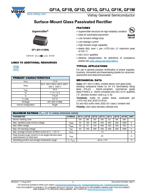
Surface-Mount Glass Passivated RectifierLINKS TO ADDITIONAL RESOURCESFEATURES•Superectifier structure for high reliability condition •Ideal for automated placement •Low forward voltage drop •Low leakage current•High forward surge capability•Meets MSL level 1, per J-STD-020, LF maximum peak of 250 °C•AEC-Q101 qualified•Material categorization: for definitions of compliance please see /doc?99912TYPICAL APPLICATIONSFor use in general purpose rectification of power supplies,inverters, converters and freewheeling diodes for consumer, automotive and telecommunication.MECHANICAL DATACase: GF1 (DO-214BA), molded epoxy over glass body Molding compound meets UL 94 V-0 flammability rating Base P/N-E3 - RoHS-compliant, commercial grade Base P/NHE3_X - RoHS-compliant and AEC-Q101 qualified (“X” denotes revision code e.g. A, B)Terminals: matte tin plated leads, solderable per J-STD-002 and JESD 22-B102E3 and HE3 suffix meet JESD 201 class 2 whisker test Polarity: color band denotes cathode endPRIMARY CHARACTERISTICSI F(AV) 1.0 AV RRM 50 V, 100 V, 200 V, 400 V, 600 V,800 V, 1000 VI FSM30 A V F 1.1 V, 1.2 V I R 5.0 μA T J max.175 °C PackageGF1 (DO-214BA)Circuit configurationSingleGF1 (DO-214BA)Superectifier®CathodeAnode3D 3D3D ModelsMAXIMUM RATINGS (T A = 25 °C unless otherwise noted)PARAMETER SYMBOLGF1A GF1B GF1D GF1G GF1J GF1K GF1M UNITDevice marking codeGA GB GD GG GJ GK GM Max. repetitive peak reverse voltage V RRM 501002004006008001000V Max. RMS voltage V RMS 3570140280420560700V Max. DC blocking voltageV DC 501002004006008001000V Max. average forward rectified current at T L = 125 °C I F(AV) 1.0A Peak forward surge current 8.3 ms single half sine-wave superimposed on rated loadI FSM 30A Operating junction and storage temperature rangeT J , T STG -65 to +175°CNote(1)Thermal resistance from junction to ambient and from junction to lead, PCB mounted on 0.2" x 0.2" (5.0 mm x 5.0 mm) copper pad areasNote(1)AEC-Q101 qualifiedRATINGS AND CHARACTERISTICS CURVES (T A = 25 °C unless otherwise noted)Fig. 1 - Forward Current Derating Curve Fig. 2 - Non-Repetitive Peak Forward Surge CurrentELECTRICAL CHARACTERISTICS (T A = 25 °C unless otherwise noted)PARAMETERTEST CONDITIONS SYMBOLGF1AGF1BGF1D GF1GGF1JGF1KGF1MUNIT Max. instantaneous forward voltage1.0 AV F1.11.2V Max. DC reverse current at rated DC blocking voltage T A = 25 °C I R 5.0μA T A = 125 °C50Typical reverse recovery time I F = 0.5 A, I R = 1.0 A, I rr = 0.25 A t rr 2.0μs Typical junction capacitance4.0 V, 1 MHzC J15pFTHERMAL CHARACTERISTICS (T A = 25 °C unless otherwise noted)PARAMETER SYMBOL GF1A GF1B GF1D GF1G GF1J GF1K GF1M UNITTypical thermal resistance (1)R θJA 80°C/WR θJL26ORDERING INFORMATION (Example)PREFERRED P/N UNIT WEIGHT (g)PREFERRED PACKAGE CODEBASE QUANTITYDELIVERY MODEGF1J-E3/67A 0.10467A 15007" diameter plastic tape and reel GF1J-E3/5CA 0.1045CA 650013" diameter plastic tape and reel GF1JHE3_A/H (1)0.104H 15007" diameter plastic tape and reel GF1JHE3_A/I (1)0.104I650013" diameter plastic tape and reel01001301101201401501601800.501.00Lead T emperature (°C)1.250.750.25170A v e r a g e F o r w a r d R e c t i f i e d C u r r e n t (A )t p , Pulse Width (ms)P e a k F o r w a r d S u r g e C u r r e n t (A )0.1101001000101Fig. 3 - Typical Instantaneous Forward Characteristics Fig. 4 - Typical Reverse Characteristics Fig. 5 - Typical Junction CapacitanceFig. 6 - Typical Transient Thermal ImpedancePACKAGE OUTLINE DIMENSIONS in inches (millimeters)1010.10.010.40.61.41.60.81.01.2Instantaneous Forward Voltage (V)I n s t a n t a n e o u s F o r w a r d C u r r e n t (A )0.11100.0120100406080Percent of Rated Peak Reverse Voltage (%)I n s t a n t a n e o u s R e v e r s e L e a k a g e C u r r e n t (µA )11001030110Reverse Voltage (V)J u n c t i o n C a p a c i t a n c e (p F )0.01100101000.10.11101T r a n s i e n t T h e r m a l I m p e d a n c e (°C /W )t - Pulse Duration (s)GF1 (DO-214BA)Mounting Pad LayoutLegal Disclaimer Notice VishayDisclaimerALL PRODUCT, PRODUCT SPECIFICATIONS AND DATA ARE SUBJECT TO CHANGE WITHOUT NOTICE TO IMPROV E RELIABILITY, FUNCTION OR DESIGN OR OTHERWISE.V ishay Intertechnology, Inc., its affiliates, agents, and employees, and all persons acting on its or their behalf (collectively,“Vishay”), disclaim any and all liability for any errors, inaccuracies or incompleteness contained in any datasheet or in any other disclosure relating to any product.Vishay makes no warranty, representation or guarantee regarding the suitability of the products for any particular purpose or the continuing production of any product. To the maximum extent permitted by applicable law, Vishay disclaims (i) any and all liability arising out of the application or use of any product, (ii) any and all liability, including without limitation special, consequential or incidental damages, and (iii) any and all implied warranties, including warranties of fitness for particular purpose, non-infringement and merchantability.Statements regarding the suitability of products for certain types of applications are based on Vishay's knowledge of typical requirements that are often placed on Vishay products in generic applications. Such statements are not binding statements about the suitability of products for a particular application. It is the customer's responsibility to validate that a particular product with the properties described in the product specification is suitable for use in a particular application. Parameters provided in datasheets and / or specifications may vary in different applications and performance may vary over time. All operating parameters, including typical parameters, must be validated for each customer application by the customer's technical experts. Product specifications do not expand or otherwise modify Vishay's terms and conditions of purchase, including but not limited to the warranty expressed therein.Hyperlinks included in this datasheet may direct users to third-party websites. These links are provided as a convenience and for informational purposes only. Inclusion of these hyperlinks does not constitute an endorsement or an approval by Vishay of any of the products, services or opinions of the corporation, organization or individual associated with the third-party website. Vishay disclaims any and all liability and bears no responsibility for the accuracy, legality or content of the third-party website or for that of subsequent links.Except as expressly indicated in writing, Vishay products are not designed for use in medical, life-saving, or life-sustaining applications or for any other application in which the failure of the Vishay product could result in personal injury or death. Customers using or selling Vishay products not expressly indicated for use in such applications do so at their own risk. Please contact authorized Vishay personnel to obtain written terms and conditions regarding products designed for such applications. No license, express or implied, by estoppel or otherwise, to any intellectual property rights is granted by this document or by any conduct of Vishay. Product names and markings noted herein may be trademarks of their respective owners.© 2022 VISHAY INTERTECHNOLOGY, INC. ALL RIGHTS RESERVED。
国军标B版六性大纲维修性大纲
PDFt件使用"pdfFactory Pro" 试用版本创建****维修性大纲维修性大纲拟制: _______________________审核: _______________________质量: _______________________标准化: _____________________批准: _______________________军代表: _____________________1概述........................................................ . (1)2引用文件........................................................ (1)3编制依据........................................................ (1)4一般要求........................................................ (1)维修性工作目标........................................................ (1)维修性定量要求........................................................ (1)维修性定性要求........................................................ (1)维修性工作项目........................................................ (1)维修性工作计划........................................................ (2)5详细要求........................................................ (2)论证阶段........................................................ (2)方案阶段........................................................ (2)制订维修性设计方案........................................................ (2)编制大纲........................................................ (2)维修性评审........................................................ (3)工程研制阶段........................................................ (3)维修性分析与预计........................................................ (3)维修性设计准II则........................................................PDFi件使用"pdfFactory Pro" 试用版本创建****维修性大纲1概述本大纲规定****维修性工作总>要求,为****开展各类维修性工作提供依据。
国军标B版六性大纲-测试性大纲
测试性大纲
拟 制: 审 核: 质 量: 标 准 化: 批 准: 军 代 表:
版次状态:000
I
PDF 文件使用 "pdfFactory Pro" 试用版本创建
目次
****测试性大纲
1 概述.................................................................................................................................................................1 2 引用文件.........................................................................................................................................................1 3 编制依据.........................................................................................................................................................1 4 术语.................................................................................................................................................................1 4.1 机内测试(BIT)
贵州白山羊的体尺与体重及其相关性
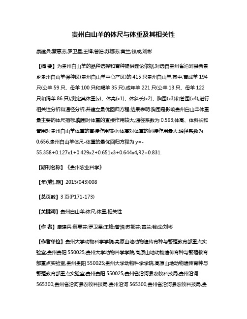
贵州白山羊的体尺与体重及其相关性康建兵;蔡惠芬;罗卫星;王锋;曾浩;苏娜芬;黄兰;钱成;刘彬【摘要】为贵州白山羊的品种选择和育种提供理论依据,对选自贵州省沿河县新景乡贵州白山羊保种区(贵州白山羊中心产区)的415只贵州白山羊,其中,育成羊194只(公羊59只、母羊100只和羯羊35只),成年羊221只(公羊13只、母羊122只和羯羊86只),测定其体重(y)、体高(x1)、体斜长(x2)、胸围(x3)和管围(x4),进行相关性分析和通径分析,并建立最优回归方程.结果表明:胸围是影响贵州白山羊体重最主要的体尺指标,胸围对体重的直接作用较大,通径系数为0.593;体高、体斜长和管围对贵州白山羊体重的直接作用较小;体高对体重的间接作用最大,通径系数为0.656.贵州白山羊体尺-体重的最优回归方程为y=-55.358+0.127x1+0.429x2+0.651x3+0.644x4,R2=0.831.【期刊名称】《贵州农业科学》【年(卷),期】2015(043)008【总页数】3页(P171-173)【关键词】贵州白山羊;体尺;体重;相关性【作者】康建兵;蔡惠芬;罗卫星;王锋;曾浩;苏娜芬;黄兰;钱成;刘彬【作者单位】贵州大学动物科学学院,高原山地动物遗传育种与繁殖教育部重点实验室,贵州贵阳550025;贵州大学动物科学学院,高原山地动物遗传育种与繁殖教育部重点实验室,贵州贵阳550025;贵州大学动物科学学院,高原山地动物遗传育种与繁殖教育部重点实验室,贵州贵阳550025;贵州省沿河县农牧科技局,贵州沿河565300;贵州省沿河县农牧科技局,贵州沿河565300;贵州省沿河县农牧科技局,贵州沿河565300;贵州大学动物科学学院,高原山地动物遗传育种与繁殖教育部重点实验室,贵州贵阳550025;贵州大学动物科学学院,高原山地动物遗传育种与繁殖教育部重点实验室,贵州贵阳550025;贵州大学动物科学学院,高原山地动物遗传育种与繁殖教育部重点实验室,贵州贵阳550025【正文语种】中文【中图分类】S827贵州白山羊是一个古老的山羊品种,已有2 000多年的饲养历史。
- 1、下载文档前请自行甄别文档内容的完整性,平台不提供额外的编辑、内容补充、找答案等附加服务。
- 2、"仅部分预览"的文档,不可在线预览部分如存在完整性等问题,可反馈申请退款(可完整预览的文档不适用该条件!)。
- 3、如文档侵犯您的权益,请联系客服反馈,我们会尽快为您处理(人工客服工作时间:9:00-18:30)。
GF1A THRU GF1M
SURFACE MOUNT GLASS PASSIVATED JUNCTION RECTIFIER
Reverse Voltage -50 to 1000 Volts
Forward Current -1.0 Ampere
FEATURES
♦ Plastic package has Underwriters Laboratory Flammability Classification 94V-0
♦ Ideal for surface mount automotive applications
♦ High temperature metallurgically bonded construction ♦ Glass passivated cavity-free junction
♦ Capable of meeting environmental standards of MIL-S-19500
♦ Built-in strain relief ♦ Easy pick and place
♦ High temperature soldering guaranteed:450°C/5 seconds at terminals
♦ Complete device submersible temperature of 265°C for 10 seconds in solder bath
MECHANICAL DATA
Ratings at 25°C ambient temperature unless otherwise specified.
SYMBOLS GF1A GF1B GF1D GF1G GF1J GF1K GF1M UNITS
Device marking code
GA
GB
GD
GG
GJ
GK
GM
Maximum repetitive peak reverse voltage V RRM 501002004006008001000Volts Maximum RMS voltage V RMS 3570140280420560700Volts Maximum DC blocking voltage
V DC 50
100
200
400600
800
1000
Volts Maximum average forward rectified current at T L =125°C
I (AV) 1.0Amp Peak forward surge current
8.3ms single half sine-wave superimposed on I FSM 30.0Amps
rated load (JEDEC Method)
Maximum instantaneous forward voltage at 1.0A V F 1.10 1.20Volts Maximum DC reverse current T A =25°C 5.0at rated DC blocking voltage T A =125°C
I R 50.0µA Typical reverse recovery time (NOTE 1)t rr 2.0µs Typical junction capacitance (NOTE 2)C J 15.0pF Typical thermal resistance (NOTE 3)
R ΘJA 80.0°C/W R ΘJL 26.0Operating junction and storage temperature range
T J , T STG
-65 to +175
°C
NOTES :
(1) Reverse recovery test conditions:I F =0.5A, I R =1.0A, I rr =0.25A (2) Measured at 1.0 MHz and applied V R =4.0 Volts
(3) Thermal resistance from junction to ambient and from junction to lead P .C.B.mounted on 0.2 x 0.2”(5.0 x 5.0mm) copper pad areas
4/98
P A T E Dimensions in inches and (millimeters)
Glass-plastic encapsulation technique is covered by
0.4
0.60.8 1.0 1.2 1.4 1.6
0.01
0.1
1
10
110
100
5.010********
110
100
1
1030
0.5
100
110120130140150160175
0 1.0020406080100
0.01
0.1
1
10
0.01
0.11
10100
0.11
10
100
RATINGS AND CHARACTERISTIC CURVES GF1A THRU GF1M
FIG.1 - FORWARD CURRENT DERATING CURVE
LEAD TEMPERATURE, °C
A V E R A G E F O R W A R D R E C T I F I E D C U R R E N T , A M P E R E S
FIG.2 - MAXIMUM NON-REPETITIVE PEAK
FORWARD SURGE CURRENT
NUMBER OF CYCLES AT 60 H Z
P E A K F O R W A R D S U R G E C U R R E N T , A M P E R E S
FIG.3 - TYPICAL INSTANTANEOUS FORWARD CHARACTERISTICS
FIG.4 - TYPICAL REVERSE CHARACTERISTICS
I N S T A N T A N E O U S F O R W A R D C U R R E N T ,A M P E R E S
I N S T A N T A N E O U S R E V E R S E C U R R E N T , M I C R O A M P E R E S
INSTANT ANEOUS FORWARD VOLT AGE,
VOLTS
FIG.5 - TYPICAL JUNCTION CAPACITANCE
J U N C T I O N C A P A C I T A N C E , p F
REVERSE VOLT AGE, VOLTS
T J =T J max.
8.3ms SINGLE HALF SINE-WAVE (JEDEC Method)
T J =25°C
T J =25°C
PULSE WIDTH=300µs 1%DUTY CYCLE
T J =25°C f=1.0 MH Z
Vsig=50mVp-p
60 H Z
RESISTIVE OR INDUCTIVE LOAD P .C.B.MOUNTED on 0.2 x 0.2”(5.0 x 5.0mm)COPPER PAD AREAS
T J =100°C
PERCENT OF RATED PEAK REVERSE
VOLT AGE, %
FIG.6 - TYPICAL TRANSIENT THERMAL IMPEDANCE
T R A N S I E N T T H E R M A L I M P E D A N C E (°C /W )
MOUNTED ON 0.20 x 0.27”(5 x 7mm)COPPER P AD AREAS
t, PULSE DURATION, sec。
