CBR6-080中文资料
威尔伍德 260-8555 -P -BK 铝制双制动主缸规格表

Bright Finish ShownIT IS THE RESPONSIBILITY OF THE PERSON INSTALLING ANY BRAKE COMPONENT OR KIT TO DETERMINE THE SUITABILITY OF THE COMPONENT OR KIT FOR THAT PARTICULAR APPLICATION. IF YOU ARE NOT SURE HOW TO SAFELY USE THIS BRAKE COMPONENT OR KIT, YOU SHOULD NOT INSTALL OR USE IT. DO NOT ASSUME ANYTHING. IMPROPERLY INSTALLED OR MAINTAINED BRAKES ARE DANGEROUS. IF YOU ARE NOT SURE, GET HELP OR RETURN THE PRODUCT. YOU MAY OBTAIN ADDITIONAL INFORMATION AND TECHNICAL SUPPORT BY CALLING WILWOOD AT (805) 388-1188, OR VISIT OUR WEB SITE AT . USE OF WILWOOD TECHNICAL SUPPORT DOES NOT GUARANTEE PROPER INSTALLATION.KNOW HOW TO PROPERLY USE THIS PRODUCT. IT IS NOT POSSIBLE OVER THE PHONE TO UNDERSTAND OR FORESEE ALL THE ISSUES THAT MIGHT ARISE IN YOUR INSTALLATION.Typical Bleeder Tube Setup and UseScan to Watch VideoHow to: Bench Bleed a Master CylinderPRESS IN AND RELEASESEVERAL TIMESBLEEDER TUBES7/8” Bore Size with PushrodCALCULATING EFFECTIVE PISTON BORE AREA TO DETERMINE PLUMBINGTo determine the effective piston bore area of any caliper, you must first calculate the area for each piston bore found on one side of the caliper. Use the formula “ Area = (bore x bore) x .785” for each piston bore size. Then, add the areas of all pistons on that one side of the caliper to determine the total effective piston bore area. Compare the difference between the front and rear calipers and attach the line from the primary outlet “A” to the calipers at the end of the vehicle with the greater total effective piston bore area.REBUILD NOTE:WILWOOD TANDEM MASTER CYLINDERS ARE NOT USER SERVICEABLE DUE TO THE NECESSITY OF SPECIAL TOOLS FOR DISASSEMBLY. IN THE EVENT REBUILDING SERVICE IS REQUIRED, PLEASE CONTACT WILWOOD TECHNICAL DEPARTMENT AT (805) 388-1188 TO ARRANGE FOR RETURNING MASTER CYLINDER FOR FACTORY REBUILD AND/OR REPAIR AT A NOMINAL COST.Plumbing Notes and Precautions• Each master cylinder kit includes one 9/16-18, one 1/2-20, and two 3/8-24 inverted flare threaded line adapters for connectionsto the brake lines (Adapters are not installed and are shipped in the reservoir of the master cylinder, remove lid to access). Two hex head plugs are supplied to block the unused outlet ports. Pressure may be taken from either side of the master cylinder. After selecting the size and location of the outlet ports to be used, lubricate adapter fitting threads lightly with silicone or lithium based grease, then install the fittings and plugs, using the aluminum crush washers and torque each to 20-25 foot pounds.• The line adapters supplied with each master cylinder are for use with double flared brake line. Use only double flared lines. Do notattempt to use single flared connections. Do not use additional sealant or any other type of gaskets on the fittings, lines, or plugs.• Connect one of the primary outlet ports (A) to the brakes at the end of the vehicle with the greatest total effective piston bore area. On most vehicles, this will be the front brake line (see note next page).• Connect one of the secondary outlet ports (B) to the brakes at the end of the vehicle with the lesser total effective piston bore area.On most vehicles, this will be the rear brake line (see note next page).• Use of reinforced flexible lines should be limited to the connection between the fixed chassis and the moving suspension. All otherlines along the fixed chassis should be hard steel lines.• On four wheel disc brake applications, where the fluid reservoir is mounted higher than the caliper bleed screws, a residualpressure valve is usually not required.• On disc brake applications where the fluid reservoir is mounted lower than the caliper bleed screws may require a 2 pound residualpressure valve. This can prevent fluid drain back and excessive pedal travel on initial engagement.• All drum brake applications require an inline 10 pound residual pressure valve.• Use an adjustable proportioning valve to set the front to rear brake bias.Tandem Master CylindersPart No.Description Part No. Description260-9439 7/8” Bore M/C - Standard Finish 260-13375 15/16” Bore M/C - Standard Finish260-9439-P 7/8” Bore M/C - Bright Finish 260-13375-P 15/16” Bore M/C - Bright Finish260-9439-BK 7/8” Bore M/C - Black Finish 260-13375-BK 15/16” Bore M/C - Black Finish260-8555 1” Bore M/C - Standard Finish 260-8556 1-1/8” Bore M/C - Standard Finish260-8555-P 1” Bore M/C - Bright Finish 260-8556-P 1-1/8” Bore M/C - Bright Finish260-8555-BK 1” Bore M/C - Black Finish 260-8556-BK 1-1/8” Bore M/C - Black Finish Components and AccessoriesPart No.Description Part No. Description260-13706 2 PSI Residual Pressure Valve 290-0632 Wilwood Hi-Temp 570 DOT 5.1 Fluid260-13707 10 PSI Residual Pressure Valve 290-6209 Wilwood EXP 600 Plus Super Hi-Temp Fluid 260-8419 Knob Adjustable Proportioning Valve260-8420 Lever Adjustable Proportioning Valve。
CBR简介

一、CBR值的相关介绍1.1、承载比(CBR)又称加州承载比,是California Bearing Ratio的缩写,由美国加利福尼亚公路局首先提出来,用于评定路基土和路面材料的强度指标。
在国外多采用CBR作为路面材料和路基土的设计参数。
我国以前路基路面的设计规范中,对路面、路基的设计参数主要采用回弹模量指标,近年来,参考了国内外的实际情况,将CBR指标列入《公路路基设计规范》和《公路路基施工技术规范》,作为路基填料选择的依据。
因此CBR值的确定对于公路工程的路基路面设计及施工都有着非常重要的意义。
1.2、CBR定义所谓CBR值就是试料贯入量达到2.5mm或5mm时的单位压力与标准碎石压入相同贯入量时的标准荷载(7MPa或l0.5MPa)的比值,用百分数来表示。
1.3、目的和适用范围确定材料是否适宜做基层或底基层,本法只适用于在规定的试筒内制件后,对各种土和路面基层、底基层材料进行承载比试验。
试件的最大粒径宜控制在20mm以内,最大不得超过40mm(圆孔筛)。
1.4、室内CBR值试验原理试验时,按路基施工时的最佳含水量及压实度要求在试筒内制备试件。
为了模拟材料在使用过程中的最不利状态,加载前饱水四昼夜。
在浸水过程中及贯入试验时,在试件顶面施加荷载板。
以模拟路面结构对土基的附加应力。
需要注意的是,贯入试验中,材料的承载能力越高,对其压入一定贯入深度所需施加的荷载越大。
二、CBR值试验步骤及注意事项2.1、备料,试验采用风干试料,按四分法取样,一次备足击实CBR试验所需试样;试样的制取应有代表性并尽量与施工实际相符《公路土工试验规程》中的“承载比(CBR)试验规定:“试样的最大粒径宜控制在20mm以内.最大不得超过40mm”。
而又有以下规定:“将具有代表性的风干试料用木碾捣碎.但应尽量注意不使土或粒料的单个颗粒破碎。
土团均应捣碎到通过5mm的筛孔”。
对于以上的这些规定,容易让人混淆:既然要过5mm的筛孔,何必要规定宜控制在20mm以内,最大不得超过40mm呢?实际工作中,到底应过怎样的筛才能保证试样的代表性呢?视材料的具体情况而定。
CBR
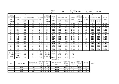
649 6.2
664 6.3
671 6.4
吸水量 (g) 343 358 332 g
CBR结果(%)
序号 6 2 4 筒质量(g) 5183 4390 5222 干密度: 试样干密 度 (g/cm3) 1.949 1.924 1.956 膨胀量: 泡水前试件高度 (mm) 120.00 120.00 120.00 3.27 泡水后试 泡水后筒 膨胀量 件高度 +试件质 (%) (mm) 量(g) 123.86 3.22 10108 123.92 3.27 9263 123.97 3.31 10153 % 吸水量: 344 30.0
1
3 427 509 525 2.03 2.52 3.02 506
649
664
671
最小CBR值 3 4 5 8
2
0.27 0.47 0.98 1.49 1.98 2.48 2.99 3.48 3.98 4.48 5.00 5.48
3
1.5 2.7 3.7 4.6 5.4 6.0 6.4 6.7 7.3 7.5 8.0 9.0
贯入量 L=2.5mm 时CBR(%)
123 222 304 378 443 493 525 550 599 616 657 739
击实次数
30
灌入杆面积1.9635
校正系数C
161.217
1
荷载测力 计百分表 单位压力 (Kpa) 读数 (0.01mm 百分表读数(mm) 左表 右表 荷载测力 单位压 贯入量L 计百分表 力 (mm) 读数 (Kpa) (0.01mm
2
百分表读数(mm) 左表 右表
3
荷载测力 贯入量L 计百分表 单位压力 百分表读数(mm) (mm) (Kpa) 读数 左表 右表 (0.01mm 贯入量L (mm)
MC-4R512FKE6D-840资料

GND LDQA8 GND LDQA6 GND LDQA4 GND LDQA2 GND LDQA0 GND LCTMN GND LCTM GND NC GND LROW1 GND LCOL4 GND LCOL2 GND LCOL0 GND LDQB1 GND LDQB3 GND LDQB5 GND LDQB7 GND LSCK VCMOS SOUT VCMOS NC GND NC VDD VDD NC NC NC NC
A1 A2 A3 A4 A5 A6 A7 A8 A9 A10 A11 A12 A13 A14 A15 A16 A17 A18 A19 A20 A21 A22 A23 A24 A25 A26 A27 A28 A29 A30 A31 A32 A33 A34 A35 A36 A37 A38 A39 A40 A41 A42 A43 A44 A45 A46
NC NC NC NC VREF GND SA0 VDD SA1 SVDD SA2 VDD RCMD GND RDQB8 GND RDQB6 GND RDQB4 GND RDQB2 GND RDQB0 GND RCOL1 GND RCOL3 GND RROW0 GND RROW2 GND NC GND RCFMN GND RCFM GND RDQA1 GND RDQA3 GND RDQA5 GND RDQA7 GND
NC NC NC NC VREF GND SCL VDD SDA SVDD SWP VDD RSCK GND RDQB7 GND RDQB5 GND RDQB3 GND RDQB1 GND RCOL0 GND RCOL2 GND RCOL4 GND RROW1 GND NC GND RCTM GND RCTMN GND RDQA0 GND RDQA2 GND RDQA4 GND RDQA6 GND RDQA8 GND
DNV挪威船级社规范中文版
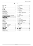
第2节 规范的范围和船级符号 ................. 8
A. 规范的应用 规范的应用范围 应用范围 ............................... 8 A 100 一般要求 .................................. 8 A 200 规范的应用范围 ............................. 8 A 300 规范的要点 ................................ 8 B. 船级符号 ................................ ..................................... ..... 9 B 100 一般要求 .................................. 9 B 200 建造符号 .................................. 9 B 300 船级主字符 ............................... 9 B 400 航区船级符号 .............................. 9 B 500 其它航行限制 .............................. 9 B 600 附加船级: 服务和类型船级符号 ............. 9 B 700 附加船级: 设备和系统船级符号 .............. 12 B 800 附加船级: 特征船级符号 .................... 14 B 900 国家法规 .................................. 14 B 1000 附加船级: NAUTICUS ........................ 14
的服务范围,且涉及: — 无论是新建造的或营运船舶的入级; — 代表国家海事主管机关执行的法定检验工作; — 船用设备和材料。
CBR历史(4)

首先讲讲CBR250,值得一提的是250毫升排量的CBR车是在400毫升排量的车出现之后三年才推出的。它是这个车系的入门车,一共有三个车款,1986年开始生产,1998年停产。
第一款车CBR250
CBR系列中,600毫升的排量只能算中等排量,它有三款车型:CBR600 F、CBR600 F
Sport和CBR600RR。其中CBR600
F采用水冷四冲程直列四缸DOHC16气门发动机,排气量为599毫升,最大功率80千瓦,变速箱为6前速变速箱。它极具运动风格而且很适合双人骑乘。
400毫升排量的车为CBR家族赢得今天的盛誉做了大量的普及工作。1983年,本田正式推出CBR系列公跑车,它就是CBR400F,1983年出品,现在几乎绝迹。1986年,本田受赛场的影响,开始推出大包围的AERO系列市售版跑车,代表作是CBR400
1994年,日本再次更改功率法,250毫升的摩托车最大功率被限定在31千瓦。MC22与MC19相比,采用了大量的新技术:重新设计了车架使之更轻量化;导风槽引入到化油器附近,而不像MC19那样基本上是个装饰;采用了全新的悬挂系统,前悬挂更新了油路设计,后悬挂采用全浮动式,并配以欧翼式后摇臂;改良了制动,为前双盘式;降低了把手、抬高了座位,提高了灵敏度;车轮为“S”形断面、6辐条式;排气管消声器为可拆式;增加了边撑保护开关……
最新本田cbr600发动机参数

長x闊x高:2,002mm x 686mm x 1,096mmCBR600RR F4軸距:1395mm最低離地距:130mm离地座高:820mm整車乾重:155kg引擎形式:水冷四衝程16活瓣DOHC 4汽缸缸徑x 衝程:67 mm x 42.5 mm壓縮比:12.2:1總排氣量:599 cc最高馬力:120ps/13,500rpm最大扭力:6.73kg-m/11,250rpm車架形式:鋁合金雙翼樑框式傳動系統:濕式多片6前速,鏈條傳動燃油供應:PGM DSFI電子燃油噴注前傾角:23.7°拖曳距:96.3mm前懸掛系統:41mm 全調校HMAS倒立套筒前叉,120mm行程後懸掛系統:Unit Pro-Link全調校氣壓彈簧避震,130mm行程輪胎(前):120/70 ZR17M/C (58W)輪胎(後):180/55 ZR17M/C (73W)前掣動系統:雙310mm鑽孔碟配四活塞放射式卡鉗後掣動系統:單220鑽孔碟配單活塞卡鉗油缸容量:18.2公升广工赛车的参数车身颜色:红白车架:焊接钢桁架车架车身材料:碳纤维车身悬架:不等长双横臂悬架长度:2900mm高度:1200mm轴距:1600mm前轮距:1250mm后轮距:1200mm离地间距:40mm整备质量:290kg前后载荷比:45:55发动机:PC35EHONDA CBR600车轮:13英寸万丰轮辋20.5X7.0-13hoosier轮胎最大功率:45Kw/8000rmp最大扭矩:60Nm/6500rmp换挡方式:手动传动:链传动滑块式限滑差速器。
本田CBR100020110815124954
本田CBR1000 2011 08 15 1249 54本田CBR1000 (2011-08-15 12:49:54)00概述本田首台----公升四缸Superbike 引擎一直以来本田都以V型引擎出战Superbike赛事,由早年的RC30、RC45到近年的 VTR1000 SPI/II,不论是四或两汽缸均是采用V型引擎规格。
来到最新的 CBR1000RR是本田多年来再一次重用横列四汽缸引擎。
998cc四汽缸 DOHC16气阀引擎为本田全新的设计,除了尺码特别小巧之外,亦加入了大量本田取材自MotoGP赛事的最新技术,包括卡式快拆波箱、 Direct AirIntake直接空气导入系统、吸气量更大的双体式圆型高流量风格及PGM-DSFI双喷咀顺序式电子燃油喷注供油系统。
在各式最新技术配合下,新引擎的最大马力达到173ps/11,250rpm,最大扭力则为11.73kg-m/8,500rpm,数值上与其它一公升级对手看齐。
再加上由行车电脑管理的可变式排气控制系统,将排气压力控制在最适当状态,令引擎的输出可以更为畅顺,低/中速的动力亦更为充沛。
当今最犟底盘组合既然本田要CBR100RR Fireblade在赛道上扬威,当然会为其配上一个犟壮的骨架,铝合金双翼梁悬吊式车架加上全功能调较的43mm直径倒立前叉,於同级车种中已是惯见的组合,加上於MotoGP赛事及CBR600RR上得到证实的Unit Pro-Link后悬挂系统,行车表现已有足够保证。
首次於本田车系上出现的Tokico直栓式对向四活塞卡钳是当今大量生产车型中的最多掣动系统,配合310直径双钻孔浮动前碟就更可提供最犟掣动效能,尾掣动则是220mm钻孔碟配单活塞卡钳,可以完全配合前掣动的表现。
轮胎组合为一公升级车种惯用的前120/70-17及后190/50-17,配用的当然是抓著力犟的高性能轮胎啦。
目前没有摘要,马上添加由CBR 900RR发展而来的CBR 1000RR,最为车友瞩目。
2019 Honda CBR500R RA 配件插座用户指南说明书
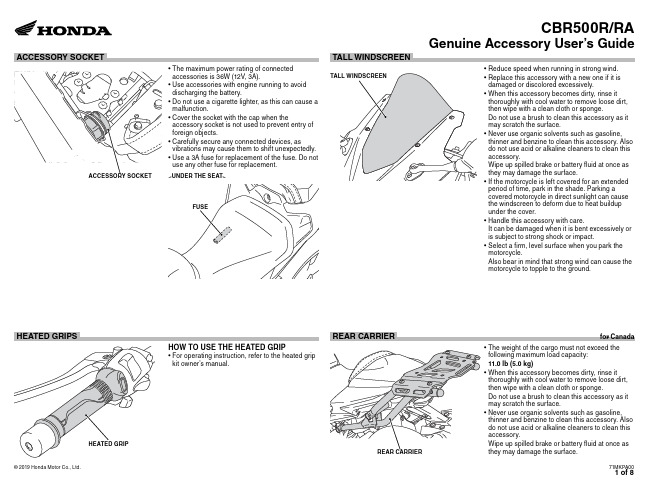
• Use a 3A fuse for replacement of the fuse. Do not use any other fuse for replacement.
damaged or discolored excessively. • When this accessory becomes dirty, rinse it
thoroughly with cool water to remove loose dirt, then wipe with a clean cloth or sponge. Do not use a brush to clean this accessory as it may scratch the surface. • Never use organic solvents such as gasoline, thinner and benzine to clean this accessory. Also do not use acid or alkaline cleaners to clean this accessory. Wipe up spilled brake or battery fluid at once as they may damage the surface. • If the motorcycle is left covered for an extended period of time, park in the shade. Parking a covered motorcycle in direct sunlight can cause the windscreen to deform due to heat buildup under the cover. • Handle this accessory with care. It can be damaged when it is bent excessively or is subject to strong shock or impact. • Select a firm, level surface when you park the motorcycle. Also bear in mind that strong wind can cause the motorcycle to topple to the ground.
洁净的Honda CBR1000RR RA S1 S2迅速变速器手把说明书
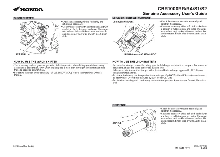
LI-ION BATTERY AND ATTACHMENT
HOW TO USE THE LI-ION BATTERY
• Check the accessory mounts frequently and retighten if necessary.
• Clean this accessory with a soft cloth soaked with a solution of mild detergent and water or a cleaner.
• Clean this accessory with a soft cloth soaked with a solution of mild detergent and water. Then wipe with a clean cloth soaked with water to clean dirt and detergent. Finally wipe dry with a soft, clean cloth.
• Clean this accessory with a soft cloth soaked with a solution of mild detergent and water. Then wipe with a clean cloth soaked with water to clean dirt and detergent. Finally wipe dry with a soft, clean cloth.
ADDC02805SAKV资料

IO = 10 A to 20 A or 20 A to 10 A di/dt = 0.5 A/ µs IO = 10 A to 20 A or 20 A to 10 A, di/dt = 0.5 A/ µs, Time for VOUT to Return within 2% of Final Value IO = 20 A, From Inhibit High to Status High IO = 12 A IO = 12 A IO = 12 A IO = 20 A IO = 20 A IO = 20 A IO = 20 A IO = 2 A IOH = 400 µA IOL = 1 mA IAUX = 5 mA, Load Current = 20 A 75 75 72 74 74 73
4
IO = 2 A to 20 A, VIN = 18 V to 40 V dc IO = 2 A to 20 A, VIN = 18 V to 40 V dc IO = 2 A to 16 A, VIN = 16 V to 50 V dc IO = 20 A, VIN = 18 V to 40 V dc VIN = 28 V dc, IO = 2 A to 20 A IO = 20 A, 5 kHz – 2 MHz BW VIN = 18 V to 40 V dc IO = 20 A, Open Remote Sense Connection VO = 90% VOUT Nom
(TC = +25؇C, VIN = 28 V dc ؎ 0.5 V dc, unless otherwise noted; full temperature range is –55؇C to +90؇C; all temperatures are case and TC is the temperature measured at the center of the package bottom.)
贝利摩6路特殊控制阀说明书
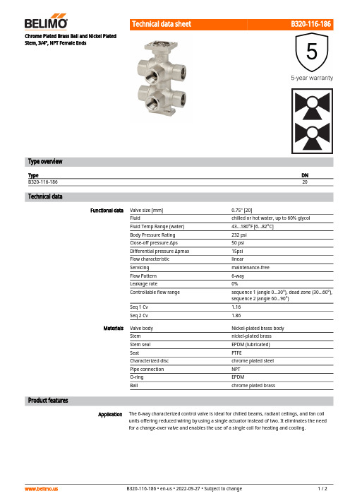
B320-116-186ApplicationChrome Plated Brass Ball and Nickel Plated Stem, 3/4", NPT Female EndsType overviewTypeDN B320-116-18620Technical dataFunctional dataValve size [mm]0.75" [20]Fluidchilled or hot water, up to 60% glycol Fluid Temp Range (water)43...180°F [6...82°C]Body Pressure Rating 232 psi Close-off pressure ∆ps 50 psi Differential pressure Δpmax 15psi Flow characteristic linearServicing maintenance-free Flow Pattern 6-way Leakage rate0%Controllable flow range sequence 1 (angle 0...30°), dead zone (30...60°), sequence 2 (angle 60...90°)Seq 1 Cv 1.16Seq 2 Cv1.86MaterialsValve body Nickel-plated brass body Stem nickel-plated brass Stem seal EPDM (lubricated)SeatPTFECharacterized disc chrome plated steel Pipe connection NPT O-ring EPDMBallchrome plated brassProduct featuresThe 6-way characterized control valve is ideal for chilled beams, radiant ceilings, and fan coil units offering reduced wiring by using a single actuator instead of two. It eliminates the need for a change-over valve and enables the use of a single coil for heating and cooling.B320-116-186 Operation A loop pressure relief is designed into port number two (2). This allows the increased pressureto dissipate to the supply loop on port number one (1). This is intended to release any pressurebuild up in the loop (coil) when the valve is in the closed position and is isolated from the systemexpansion vessel. The change in pressure occurs due to a change in the media temperature inthe coil while isolated from the pressure vessel. The pressure relief does not affect the efficiencyof the system because cross-flow cannot occur between the heating and cooling loops. Thesystem loops (heating/cooling) should share a common expansion vessel to keep the systempressure and volume balanced.Flow/Mounting detailsAccessoriesMechanical accessories Description TypeFixing bracket for 6-way valve DN 15/20ZR-004 DimensionsType DN WeightB320-116-18620 4.63 lb [2.1 kg]A B C D E F G H1H27.5" [191] 3.9" [100]9.0" [229]7.6" [194] 2.0" [51]2.0" [51]2.4" [60]1.2" [30]0.6" [15]LRX24-MFTModulating, Non-Spring Return, 24 V, Multi-Function Technology®Technical dataElectrical dataNominal voltageAC/DC 24 V Nominal voltage frequency 50/60 HzNominal voltage rangeAC 19.2...28.8 V / DC 21.6...28.8 V Power consumption in operation 2.5 W Power consumption in rest position 1.2 W Transformer sizing 5 VAElectrical Connection18 GA plenum cable with 1/2" conduitconnector, degree of protection NEMA 2 / IP54, 1 m 3 m and 5 mOverload Protection electronic thoughout 0...90° rotation Electrical Protectionactuators are double insulated Functional dataOperating range Y 2...10 VOperating range Y note 4...20 mA w/ ZG-R01 (500 Ω, 1/4 W resistor)Input Impedance100 kΩ for DC 2...10 V (0.1 mA), 500 Ω for 4...20 mA, 1500 Ω for PWM and On/Off Operating range Y variable Start point 0.5...30 V End point 2.5...32 VOperating modes optional variable (VDC, on/off, floating point)Position feedback U 2...10 V Position feedback U note Max. 0.5 mA Position feedback U variable VDC variableDirection of motion motor selectable with switch 0/1Manual override external push button Angle of rotation 90°Angle of rotation note adjustable with mechanical stop Running Time (Motor)150 s / 90°Running time motor variable 35...150 s Noise level, motor 35 dB(A)Position indicationMechanically, pluggable Safety dataPower source ULClass 2 Supply Degree of protection IEC/EN IP54Degree of protection NEMA/UL NEMA 2Enclosure UL Enclosure Type 2Agency Listing cULus acc. to UL60730-1A/-2-14, CAN/CSA E60730-1:02, CE acc. to 2014/30/EU Quality Standard ISO 9001UL 2043 CompliantSuitable for use in air plenums per Section 300.22(C) of the NEC and Section 602 of the IMCAmbient humidityMax. 95% RH, non-condensingLRX24-MFTFootnotesSafety dataAmbient temperature -22...122°F [-30...50°C]Storage temperature -40...176°F [-40...80°C]Servicingmaintenance-free Weight Weight1.5 lb [0.70 kg]MaterialsHousing material Galvanized steel and plastic housing†Rated Impulse Voltage 800V, Type action 1.B, Control Pollution Degree 3.AccessoriesGatewaysDescriptionType Gateway MP to BACnet MS/TP UK24BAC Gateway MP to Modbus RTU UK24MOD Gateway MP to LonWorksUK24LON Electrical accessoriesDescriptionType Battery backup system, for non-spring return models NSV24 US Battery, 12 V, 1.2 Ah (two required)NSV-BAT Auxiliary switch 1 x SPDT add-on S1A Auxiliary switch 2 x SPDT add-onS2AFeedback potentiometer 140 Ω add-on, grey P140A GR Feedback potentiometer 1 kΩ add-on, grey P1000A GR Feedback potentiometer 10 kΩ add-on, grey P10000A GR Feedback potentiometer 2.8 kΩ add-on, grey P2800A GR Feedback potentiometer 500 Ω add-on, grey P500A GR Feedback potentiometer 5 kΩ add-on, greyP5000A GR ToolsDescriptionTypeConnection cable 10 ft [3 m], A: RJ11 6/4 ZTH EU, B: 3-pin Weidmüller and supply connectionZK4-GEN Service Tool, with ZIP-USB function, for programmable and communicative Belimo actuators, VAV controller and HVAC performance devicesZTH USElectrical installationINSTALLATION NOTESProvide overload protection and disconnect as required.Actuators may be connected in parallel. Power consumption and input impedance must beobserved.Actuators may also be powered by DC 24 V.Only connect common to negative (-) leg of control circuits.A 500 Ω resistor (ZG-R01) converts the 4...20 mA control signal to 2...10 V.Control signal may be pulsed from either the Hot (Source) or Common (Sink) 24 V line.For triac sink the Common connection from the actuator must be connected to the Hotconnection of the controller. Position feedback cannot be used with a triac sink controller; theactuator internal common reference is not compatible.IN4004 or IN4007 diode. (IN4007 supplied, Belimo part number 40155).Actuators with plenum cable do not have numbers; use color codes instead.Meets cULus requirements without the need of an electrical ground connection.Warning! Live electrical components!During installation, testing, servicing and troubleshooting of this product, it may be necessary to work with live electrical components. Have a qualified licensed electrician or other individual who has been properly trained in handling live electrical components perform these tasks. Failure to follow all electrical safety precautions when exposed to live electrical components could result in death or serious injury.LRX24-MFT Wiring diagramsOn/Off Floating PointVDC/mA Control PWM ControlOverride Control。
CBR值定义、标准

CBR值一、根据质量检验评定标准规定高速一级公路路基填筑上路床CBR值不小于8%,下路床不小于6%;路床一下不小于5%。
(CBR值为用检测材料标准击实成型试件,饱水4昼夜后用贯入阻力仪测试贯入量与阻力关系。
当贯入量为2.5mm时的阻力与标准阻力0.7MPa的比值就是该材料的CBR值%)二、路基CBR值编辑词条目录1路基CBR值在公路试验中有一个承载比试验(CBR)记录里面的基本数据填写完毕后,可以得出一系列贯入量l 结果和单位压力p结果根据这一系列结果,以贯入量l为纵坐标,以单位压力p为横坐标,在直角坐标系上标出这些点在根据这些点的位置,用模糊数学(线形回归)的理论,推出曲线的公式,根据公式,将这些点绘制出一个圆滑的关系曲线.然后就可以根据曲线得出贯入量l =2.5 和贯入量l=5.0 时候单位压力P的数值了.CBR(California bearing ratio)是美国加利福尼亚州提出的一种评定基层材料承载能力的试验方法。
承载能力以材料抵抗局部荷载压入变形的能力表征,并采用标准碎石的承载能力为标准,以相对值的百分数表示CBR值。
这种方法后来也用于评定土基的强度。
由于CBR的试验方法简单,设备造价低廉,在许多国家得到广泛应用。
采用CBR法确定沥青路面厚度,有配套的图表,应用十分方便,受到工程技术人员的欢迎。
测定加州承载比(CBR)的仪具:由机架、加荷装置、测力装置、贯入压头、百分表等组成。
三、路基填料CBR路基填料的承载比(CBR值)是土体抗局部剪切力(潜在强度)的反映,是评价其路用性能的重要指标。
四、现场CBR值测试和贝克曼梁测路基路面回弹模量测试(通过测出的弯沉值求得回弹模量),CBR值是测强度的,弯沉值是测回弹模量的,他们检测的参数不同。
CBR还有一个室内检测试验,和现场CBR检测方法不同,但是都是测其强度的,而贝克曼梁要是用在新建或者老路检测某个路段的弯沉值则是检测其承载能力的。
五、CBR的三个表,两个是读位移变形的百分表,分左表和右表,最后的贯入量是L=(R左+R右)/2。
贝利摩 G7150D 6寸三向分流阀说明书

G7150D•••••Type overviewType DN G7150D150Technical dataFunctional dataValve size [mm]6" [150]Fluidchilled or hot water, up to 60% glycol Fluid Temp Range (water)32...150°F [0...65°C]Body Pressure Rating ANSI Class 125, up to 175 psi below 150°F Flow characteristic linearServicing repack/rebuild kits available Rangeability Sv 50:1Flow Pattern 3-way Diverting Leakage rateANSI Class III Controllable flow range stem up - open AB – B Cv248MaterialsValve body Cast iron - ASTM A126 Class B Valve plug bronze Stem stainless steelStem seal NLP EPDM (no lip packing)SeatStainless steel AISI 316Pipe connection125 lb flanged Suitable actuatorsNon-Spring EVB(X)Spring(2*AFB(X))Safety notesWARNING: This product can expose you to lead which is known to the State of California to cause cancer and reproductive harm. For more information go to The valve has been designed for use in stationary heating, ventilation and air-conditioning systems and must not be used outside the specified field of application, especially in aircraft or in any other airborne means of transport.Only authorized specialists may carry out installation. All applicable legal or institutional installation regulations must be complied during installation.The valve does not contain any parts that can be replaced or repaired by the user.When determining the flow rate characteristic of controlled devices, the recognised directives must be observed.G7150D Product featuresFlow/Mounting detailsDimensionsType DN WeightG7150D150200.66 lb [91 kg]EVB, EVX, RVB, RVXA B C D E F Number of Bolt Holes16.1" [410]14.1" [359]30.5" [775]19.4" [492]5.6" [142]5.6" [142]82*AFB, 2*AFXA B C D E F Number of Bolt Holes16.1" [410]14.1" [359]34.0" [864]23.0" [584]5.6" [142]5.3" [135]8Modulating, Spring Return, 24 V, 0 to 135 ΩInputTechnical dataElectrical data Nominal voltage AC/DC 24 VNominal voltage frequency50/60 HzNominal voltage range AC 19.2...28.8 V / DC 21.6...28.8 VPower consumption in operation7.5 WPower consumption in rest position 3 WTransformer sizing20 VAElectrical Connection18 GA appliance cable, 1 m, 3 m or 5 m, with1/2" conduit connector, degree of protectionNEMA 2 / IP54Overload Protection electronic throughout 0...95° rotationFunctional data Operating range Y0...135 ΩOperating range Y note Honeywell Electronic Series 90, input 0...135 ΩPosition feedback U 2...10 VPosition feedback U note Max. 0.5 mAPosition feedback U variable VDC variableDirection of motion motor selectable with switch 0/1Direction of motion fail-safe reversible with cw/ccw mountingManual override 5 mm hex crank (3/16" Allen), suppliedAngle of rotation95°Angle of rotation note adjustable with mechanical end stop, 35...95°Running Time (Motor)150 s / 90°Running time motor variable70...220 sRunning time fail-safe<20 sOverride control MIN (minimum position) = 0%MID (intermediate position) = 50%MAX (maximum position) = 100%Noise level, motor40 dB(A)Noise level, fail-safe62 dB(A)Position indication MechanicalSafety data Power source UL Class 2 SupplyDegree of protection IEC/EN IP54Degree of protection NEMA/UL NEMA 2Enclosure UL Enclosure Type 2Agency Listing cULus acc. to UL60730-1A/-2-14, CAN/CSAE60730-1:02, CE acc. to 2014/30/EUQuality Standard ISO 9001UL 2043 Compliant Suitable for use in air plenums per Section300.22(C) of the NEC and Section 602 of theIMCAmbient humidity Max. 95% RH, non-condensingFootnotesSafety dataAmbient temperature -22...122°F [-30...50°C]Storage temperature -40...176°F [-40...80°C]Servicingmaintenance-free Weight Weight9.26 lb [4.2 kg]MaterialsHousing material Galvanized steel and plastic housing*Variable when configured with MFT options.AccessoriesGatewaysDescriptionType Gateway MP to BACnet MS/TP UK24BAC Gateway MP to Modbus RTU UK24MOD Gateway MP to LonWorksUK24LON Electrical accessoriesDescriptionType Service Tool, with ZIP-USB function, for programmable andcommunicative Belimo actuators, VAV controller and HVAC performance devicesZTH USToolsDescriptionTypeConnection cable 10 ft [3 m], A: RJ11 6/4 ZTH EU, B: 3-pin Weidmüller and supply connectionZK4-GEN Service Tool, with ZIP-USB function, for programmable and communicative Belimo actuators, VAV controller and HVAC performance devicesZTH USElectrical installationMeets cULus requirements without the need of an electrical ground connection.Provide overload protection and disconnect as required.Actuators may also be powered by DC 24 V.Actuators and controller must have separate transformers.Consult controller instruction data for more detailed information.Resistor value depends on the type of controller and the number of actuators. No resistor isused for one actuator. Honeywell® resistor kits may also be used.To reverse control rotation, use the reversing switch.Actuators may be controlled in parallel. Current draw and input impedance must be observed.Wiring diagrams High Limit ControlLow Limit ControlTypical and Override ControlMultiple ActuatorsMultiple Actuators with Minimum Position PotentiometerMultiple Actuators Used with W973, W7100 and T775。
承载比(CBR)试验 (2)
意义(为什么)
• 1. CBR 指标列入了我国《公路路基设计规 范》、《公路路基施工技术规范》,作为 路基填料选择的依据。 • 2.在铁路路基施工中也采用 CBR 作为评 价填料强度的辅助指标。 CBR 试验的优点 是能测出填料浸水后的强度,这一指标对 铁路浸水路基非常重要。 •
• 3、CBR用于评定基层、垫层或土基材料的相对承载力, 是一项反映土体抗垂直位移和抵抗局部荷载压入变形能力 的指标,当接近极限平衡条件时,兼可反映土体抗剪强度 的相对量度。 • 4、CBR值反映了路基填筑材料的水稳性和整体强度的大 小,不仅可与无侧限抗压强度试验作为无机结合材料的试 验补充,还解决了砂和砂砾类建筑材料因颗粒间没有粘聚 力,无法利用无侧限抗压强度试验的问题。 • CBR是表征路基土、粒料、稳定土强度的一种指标,并 采用标准碎石的承载能力为标准,以相对值的百分数表示 CBR值。目前CBR做为公路工程评价土的性质的重要指 标,并且即将引入铁路土工试验,CBR试验已成为路基 开工前必做的一项试验。而该指标的使用,为我国公路建 设中正确选用路基填料,确保公路工程质量提供了重要依 据,发挥了巨大作用。因此,研究各种土的CBR试验有着 深远的意义。
试验步骤
• • • • • • • 简单总结 1、试样准备 2、击实制样 3、预压制样 4、泡水测膨胀量 5、贯入试验 6、结果整理
二、检测器具
• 1.圆孔筛:孔径38mm、25mm、 20mm 及5mm筛各一个。 • 2.重型标准击实仪器设备:试筒、夯锤等。
• 3.贯入杆:端面直径50mm、长100mm的金属柱。
五、结果整理
5.结果整理
(1)以单位压力p为横坐标,贯入量L为纵坐标,绘制p-L关系曲线,如图所示。
图 6 单位压力与贯入量的关系曲线
