无刷使用维护说明书
BLDC-5025A 直流无刷电机驱动器用户使用手册说明书
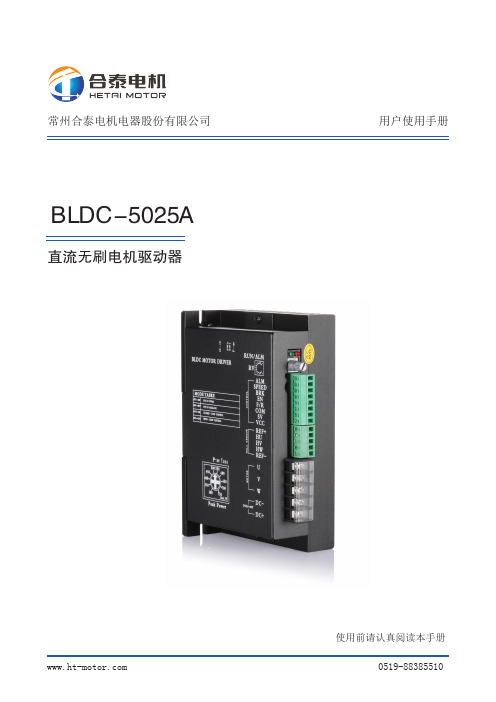
BLDC-5025A直流无刷电机驱动器使用前请认真阅读本手册用户使用手册常州合泰电机电器股份有限公司*************11 简介BLDC-5025A 直流无刷电机驱动器是由常州合泰电机电器股份有限公司自主研发完成的,针对中功率低压直流无刷电机驱动的高性能无刷驱动产品。
BLDC-5025A 直流无刷电机驱动器适用于功率为750W 及以下三相直流无刷电机。
本产品设计采用先进的DSP 控制技术,具有大扭矩,低噪声,低振动,快速启停等特性。
同时具备PID 电流及速度闭环控制、过压,欠压,过流,过温等保护功能。
实现了手动速度调节与上位机模拟电压速度调节,上位机脉冲频率速度调节的完美统一。
同时具有RS232 通讯控制功能(选配),也可根据本产品所提供RS232 通讯协议自主设计上位控制器进行电机控制。
1.2 使用特点■ 产品易使用、快上手① 自带电位器可调速② 接上开关、就可以实现正反转、启停、刹车■ 多样化调速手段① 内置电位器调速② 外接电位器调速③ 外部信号调速④ 脉冲调速■ 速度信号输出、报警输出■自带电流设定保护功能2 电气性能及环境指标2.1 电气指标驱动器参数最小值额定值最大值输入电压 DC (V)184850输出电流(A)2545适用电机转速(rpm)020000霍尔信号电压(V) 4.55 5.5霍尔驱动电流(mA)20外接调速电位器(KΩ)102.2 环境指标环境因素环境指标冷却方式自然冷却或强制冷却使用场合避免粉尘,油污及腐蚀性气体使用温度10℃~+50℃环境湿度80%RH(无结露)震动 5.7m/S2 max 存储温度-20℃~+125℃■ 开环、闭环速度控制P-sv 电流设定电位器,通过设定运行电流最高限定值,便可实现电机过载保护。
当电机运行电流超过设定值时,保护功能启动,驱动器停止作业保护电机。
23 机械尺寸及安装图4 驱动器接口及接线示意图 4.1 驱动器接口REF-HW HV HU REF++SPEEDSV:COM:BRK:RV:VCC:34.2 输入口连接4.3 输出口连接信号端子信号名内容输入SV 调速信号输入端口① 外接输入调速电位器; ② 模拟信号输入; ③ 脉冲调速信号输入。
无刷电机驱动器说明书
80
58
120
重量
Kg
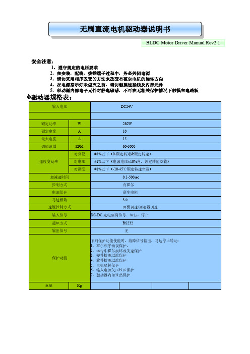
驱动器接品图
无刷直流电机驱动器说明书
BLDC Motor Driver Manual Rev2.1
BLDC MoTor river
浅绿色 粉红色
棕色 白色
橙色(+5V) 紫色(SP) 灰色(GND)
绿色(复位) 红色(+5V) 黑色(GND) 蓝色(RXD) 黄色(TXD)
开/停 启停控制线 无水断电开关
控制方式
有霍尔电源保护刹车电阻马达相数 速度控制方式
输入信号
3Φ 面板调速/调速器调速 DC-DC 光电隔离信号:运行,停止
通讯方式 输出信号
RS232 无
保护功能
下列保护功能使能时,故障信号输出,马达停止转动:
1,霍尔相序错误保护, 2,运行中霍尔损坏或失速保护 3,硬件检测过流保护 4,软件检测过流保护 5,电机堵转保护 6,输入电源欠压过压保护 7,驱动器内部过热保护
驱动器规格表:
输入电压
DC24V
额定功率
W
额定电流
A
最大电流
A
调速范围
RPM
对负载
速度变动率
对电压
对温度
加减速时间
280W 10 15 60-3000 ±1%以下(0-额定转矩&额定转速) ±1%以下(电源电压±10%内,额定转速空载) ±1%以下(-10-45℃额定转速空载) 0.1-500sec
无刷直流电机驱动器说明书
BLDC Motor Driver Manual Rev2.1
安全注意:
1,遵守规定的电压要求 2,在安装,配线,拔插端子过程中,务必关闭电源 3,请勿采用相序改变的方法来改变有霍尔电机的旋转方向 4,在电源指示灯未熄灭之前,请勿触摸连接线及内部元件 5,驱动器内部电子元件对静电敏感,不可在无相关保护情况下触摸主电路板
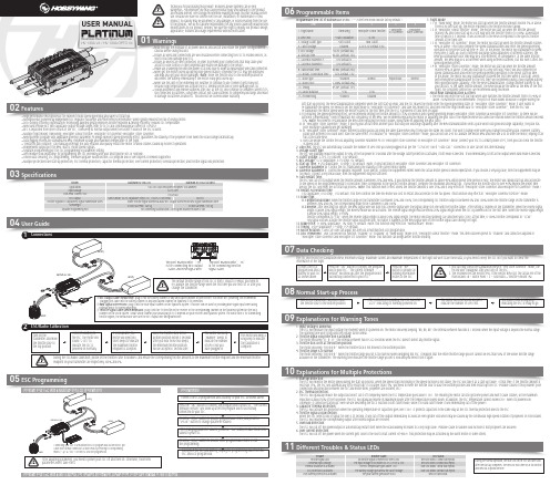
无刷电动调速器用户手册说明书
0103Specifications04User Guide05ESC Programming06Programmable Items07Data CheckingProgrammable Item List of Platinum 60A V4 ESC. (“*” in the form below indicate factory defaults. )USER MANUALHV 130A V4 / HV 130A OPTO V4Brushless Electronic Speed Controller1. Flight Mode:1.1 In “Fixed-wing” mode, the motor will start up when the throttle amount reaches 5% or above. There is no soft start-up, the motor responds to the throttle increase rapidly.1.2 In “Helicopter (Linear Throttle)” mode, the motor will start up when the throttle amount reaches 5% and it will start up in a soft way with the throttle (from 0 to 100%) acceleration time is fixed to 3.5 seconds. It will accelerate to the RPM corresponds to the specific throttle amount at the fixed rate.1.3 In “Helicopter (Elf Governor)” mode, the motor will start up when the throttle amount reaches 40% or above. And it will complete the speed standardization and enter the speed-governing operation in the preset start-up time (4~25s). In this mode, the motor will standardize its speed every time it starts up. Due to different discharge rates/capabilities of different batteries, the RPM you standardize each time may be a little different. In consequence, at the same throttle amount, the RPM may be a bit different when using different batteries, but this won’t affect the speed-governing effect.1.4 In “Helicopter (Store Governor)” mode, the motor will start up when the throttle amount reaches 40% or above. It will also start up in a very soft way. And it will also complete the speed standardization and enter the speed-governing operation in the preset start-up time. In this mode, the motor will only standardize its speed the first time when it starts up. When performing RPM standardization for the first time, we recommend using a fully-charged battery with good discharge capability. After the RPM standardization, change another battery to fly your aircraft. At the same throttle amount, the RPM should be the same as the RPM of the first flight. For consistent control feel, we recommend using this mode. About RPM Standardization & OthersI. The motor will enter the soft start-up when user switches the throttle amount from 0 to 40% or above (50%throttle is recommended). The pitch of main blades should be 0 degree during the• High performance microprocessor for excellent motor speed-governing and super soft start-up.• Microprocessor powered by independent DC regulator has better anti-interference performance, which greatly reduces the risk of losing control.• DEO (Driving Efficiency Optimization) Technology adopted greatly improves throttle response & driving efficiency, reduces ESC temperature.• New switch-mode BEC with adjustable output voltage ranges from 5V to 8V and continuous/peak current of 10A/25A.• BEC is separated from other circuits of the ESC, it will keep its normal output when the MOSFET board of the ESC is burnt. • Multiple flight modes: Fixed-wing, Helicopter (Linear Throttle), Helicopter (Elf Governor),Helicopter (Store Governor).• New governor program with adjustable governor parameter P/I brings excellent speed-governing effect, guarantees the stability of the propeller’s revs when the load changes dramatically. • Data logging records the standardized RPM, minimum voltage and maximum temperature of the flight.• "Restart in auto rotation" can manually interrupt the auto rotation and quickly restart the motor to avoid crashes caused by incorrect operations. • Independent output port for RPM (that is: motor speed) signals.• Separate programming port for ESC programming or parameter setting.• WIFI module (sold separately) for programming the ESC wirelessly with your smart phone (IOS or Android).• Online data checking, ESC programming, firmware upgrade (Multifunction LCD program box or WIFI Express is needed) supported.• Multiple protections like start-up protection, ESC thermal protection, capacitor thermal protection, over-current protection, overload protection, and throttle signal loss protection.Model Applications Input Voltage Cont./Peak Current (10s)BEC OutputThrottle Signal/BEC Output/RPM Signal Transmission WiresSize/WeightSeparate Programming PortPlatinum HV 130A V4White Throttle Signal Wire/Red & Black BEC Output Wires/Yellow RPM Signal Transmission WireFor connecting Multifunction LCD Program Box/WIFI module or fanSwitch-mode, 5V-8V Adjustable (Step:0.1V), 10A/25A Cont./Peak101x45.5x27mm / 168.5gProgrammingConnect the LCD program box and a battery to your ESC as shown above.successfully connected to your ESC.relates to the ESC.main blades =R ÷ Motor Poles ÷ 2 ÷ Gear Ratio × Throttle Amount (%).channel on the VBAR system. About which channel you should plug it in, it depends on your receiver and flybarless system. The White wire is for transmitting Program Your ESC with a WIFI Express: For detailed information, please refer to the user manual of WIFI Express.The ESC will record the standardized RPM, minimum voltage, maximum current and maximum temperatures of the flight but won’t save these data, so you need to keep the ESC on if you want to check theinformation of the flight.08Normal Start-up ProcessTurn on the transmitter, and then move the throttle stick to the bottom position.After connected to a battery, the ESC will emit “♪123” indicating it’s normally powered on.The motor will emit several beeps to indicate the number of LiPo cells.The motor emits a long beep indicating the ESC is ready to go.09Explanations for Warning Tones1. Input voltage is abnormal:The ESC will measure the input voltage the moment when it’s powered on. The motor will keep beeping “BB, BB, BB” (the interval between two BBs is 1 second) when the input voltage is beyond the normal range. The warning tone won’t stop until the voltage turns normal. 2. Throttle signal loss protection is activated:The motor will beep “B-, B-, B-” (the interval between two B-s is 2 seconds) when the ESC doesn’t detect any throttle signal. 3. Throttle stick is not at the bottom position:The motor will beep “B-B-B-B-B-” when the throttle stick is not moved to the bottom position.4. Throttle range is to narrow:The motor will beep “B-B-B-B-B-” when the throttle range you set is too narrow (when designing this ESC, it requires that the entire throttle range you set cannot be less than 50% of the whole throttle range available on the transmitter.) The warning tone indicates the throttle range you set is void and you need to set it again.10Explanations for Multiple Protections11Different Troubles & Status LEDs1. Start-up Protection:The ESC will monitor the motor speed during the start-up process. When the speed stops increasing or the speed increase is not stable, the ESC will take it as a start-up failure. At that time, if the throttle amount is less than 15%, the ESC will automatically try to restart up; if it is larger than 15%, you need to move the throttle stick to back the bottom position and then restart up the ESC. (Possible causes of this problem: poor connection/ disconnection between the ESC and motor wires, propellers are blocked, etc.)2. ESC Thermal Protection:The ESC will gradually reduce the output but won’t cut it off completely when the ESC temperature goes above 110℃. For ensuring the motor can still get some power and won’t cause crashes, so the maximum reduction is about 50% of the full power. The ESC will gradually resume its maximum power after the temperature lowers down. In addition, the ESC temperature cannot exceed 70℃ when it’s powered on. Otherwise, it cannot be started up. (Here we are describing the ESC’s reaction in soft cutoff mode, while if in hard cutoff mode; it will immediately cut off the power.) 3. Capacitor Thermal Protection:The ESC will activate this protection when the operating temperature of capacitors goes over 130℃. It protects capacitors in the same way as the ESC thermal protection does to the ESC .4. Throttle Signal Loss Protection:When the ESC detects loss of signal for over 0.25 second, it will cut off the output immediately to avoid an even greater loss which may be caused by the continuous high-speed rotation of propellers or rotor blades. The ESC will resume the corresponding output after normal signals are received. 5. Overload Protection:The ESC will cut off the power/output or automatically restart itself when the load suddenly increases to a very high value. (Possible cause to sudden load increase is that propellers are blocked.)6. Over-current Protection:The ESC will cut off the power when the current gets close to the short circuit current (of 400A). This protection may be activated by the burnt motor or some others.soft start-up process, the RPM standardization completes when the soft start-up ends, and the ESC makes the motor enter the speed-governing state. In “Helicopter (Store Governor)” mode, if user wants to re-standardize the speed, he needs to set the flight mode to “Helicopter (Elf Governor)” and save this mode first, and then reset the flight mode back to “Helicopter (Store Governor)”, then the ESC will re-standardize the motor speed when the motor rotates for the first time after the ESC is powered off and then on again.II. For ensuring the speed-governing effect, we recommend setting the throttle amount to 85% or below in both speed-governing modes (Helicopter (Store Governor) & Helicopter (Elf Governor)), so there will besufficient compensating room to maintain the consistency of the RPM. We recommend replacing the motor or adjusting the gear ratio if the expected RPM still cannot be reached when the throttle amount exceeds 85%. (Note: You need to re-standardize the RPM after replacing the motor, blades, body frame or adjusting the gear ratio.)III. In “Helicopter (Store Governor)” mode, if you fly your aircraft with another pack that has poor discharge capability after the RPM standardization (with a pack which has good discharge capability), the pack has poor discharge capability will get damaged.IV. In “Helicopter (Store Governor)” mode, different battery packs can bring the same stable RPM only if they have the same cell count. This won’t change even when you change the battery pack. However, battery packs with different cell count don’t have the same effect. For instance, in “Helicopter (Store Governor)” mode, you can not use a 4S to calibrate the motor RPM and then use a 6S to drive the motor, hoping it can run at the same RPM.V. User can decide the control feel via adjusting Governor Parameter P/I. In “Helicopter (Store Governor) or Helicopter (Elf Governor)” mode, connect your ESC to a smart phone or PC, then you can check the throttle vs speed chart.2. LiPo Cells: The ESC will automatically calculate the number of LiPo cells you have plugged in as per the “3.7V/Cell” rule if “Auto Calc.” is selected. Or user can set this item manually. 3. Voltage Cutoff Type:The ESC will gradually reduce the output to 50% of the full power in 3 seconds after the voltage cutoff protection is activated, if soft mode is selected . It will immediately cut off all the output when hard mode is selected. 4. Cutoff Voltage: 2.8V-3.8V (custom), 3.0V (default).5. BEC Voltage: 5-8V (adjustable), 0.1V (step), 6V (default).6. Start-up Time: 4-25s (adjustable), 1s (step), 15s (default). (Note: It only functions in Helicopter (Store Governor) and Helicopter (Elf Governor))7. Governor Parameter P: Control the ESC maintaining the stability of the current motor speed.8. Governor Parameter I: Control the dynamic response. To be specific, control the supplement extent when the actual motor speed is below expectation. If you choose a very big value, then the supplement may be too much. If select a very small value, then the supplement may not sufficient.9. Auto Restart Time:the ESC will cut off its output when the throttle amount is between 25% and 40%. If you increase the throttle amount to above 40% within preset time period (0-90s), the motor will rapidly start up and accelerate to the speed (in the programmed Restart Acceleration Time) corresponds to the specific throttle amount, complete the shutdown and restart up . If you move the throttle stick to over 40% beyond the preset time period, the ESC will enter the soft start-up process. (Note: This function won’t effect unless the throttle amount is over 25% and it only effects in “Helicopter (Store Governor) and Helicopter (Elf Governor)” mode.)10. Restart Acceleration Time:1-3s (adjustable), 0.5s (step), 1.5s (default). This item controls the time the motor will cost to restart and accelerate to the full speed. (This function only effects in “Helicopter Governor Elf/Store” mode) 11. Brake Type:11.1 Proportional Brake: when the throttle range on the transmitter is between 20% and 100%, the corresponding ESC throttle output is between 0% and 100%.When the throttle range on the transmitter is between 20% and 0%, the corresponding brake force is between 0 and 100%.11.2 Reverse: after selecting this option, the RPM signal wire will turn into a reverse signal wire (the signal range is in line with the throttle range). After setting a channel on the transmitter, when the reverse signal length is above 20% signal length, the Reverse mode will be activated. The reverse signal length must be below 20% signal length when the ESC is powered on for the first time. When the reverse signal length is below 20% signal length, 0-100%throttle corresponds to “CW”; when the reverse signal length is above 20% signal length, the motor will stop spinning CW (and then spin CCW); at this time, 0-100% throttle corresponds to “CCW”. Any signal loss will activate the throttle signal loss protection, no matter it happens to the RPM signal wire or the throttle signal cable during the flight.12. Brake Force: 0-100% (adjustable), 1% (step), 0 (default). (Note: this function only effects in “Normal Brake” mode.)13. Timing: 0-30° (adjustable), 1° (step), 15° (default).14. Motor Rotation: CW/CCW. User can adjust this item via a multifunction LCD program box.15. DEO (Freewheel): User can decide this function “Enabled” or “Disabled” in “Fixed Wing” mode or in “Helicopter (Linear Throttle)” mode. This item has been preset to “Enabled” and cannot be adjusted in “Helicopter (Store Governor) and Helicopter (Elf Governor)” mode. This function can brings better throttle linearity.During the normal operation, the Blue LED on the ESC will turn solid after the start-up completes. The Red LED will come on at full throttle and dies out at partial throttle.。
三相直流无刷霍尔电机驱动器说明书
前言本款产品适合驱动持续工作电流在10A以下、额定电压范围在12V~40V之间的任何一款三相直流无刷霍尔电机。
具有免维护、长寿命、低速下总能保持最大转矩等优势。
本产品广泛应用于针织设备、医疗设备、食品机械、电动工具、园林机械、智能家居等电气自动化控制领域。
本手册阐述了该驱动器的的功能、安装、调试、维护、运行等方面的内容。
使用产品前,请认真阅读本手册并熟知本产品的安全注意事项。
在使用本款产品时,若有疑问,请仔细查阅产品说明书或致电我公司售后服务部,我们将竭诚为您服务。
安全注意事项警示标志:危险:表示该操作错误可能危及人身安全!注意:表示该操作错误可能导致设备损坏!注意事项:安装:防止灰尘、腐蚀性气体、导电物体、液体及易燃物侵入,并保持良好的散热条件。
接线:请由专业人员仔细阅读完使用说明之后进行接线作业;接线必须在电源断开的状态下进行,防止电击。
通电前:接通电源前检查并保证接线的准确无误;请确认输入电源与驱动器的额定工作电压及极性是否一致;通电中:驱动器接通电源后,请勿直接接触输出端子,有的端子上有高电压,非常危险;请确保在驱动器指示灯熄灭后再对驱动器的接线端子进行插拔;请勿对驱动器随意进行耐高压与绝缘性能试验;请勿将电磁接触器、电磁开关接到输出回路。
目录前言 (1)安全注意事项 (2)目录 (3)一.概述 (5)1.型号说明 (5)2.功能参数 (5)3.功能特点 (6)二.端口说明 (7)1.接口定义 (7)2.接线示意图 (8)3.安装尺寸 (9)三.功能与使用 (10)1.出厂说明 (10)2.操作步骤说明 (10)2.1外置电位器调速 (11)2.2外部电压调速 (11)2.3外部PWM信号调速 (11)2.4CAN总线控制 (11)3.功能端子说明 (12)3.1F/R端子:正反转功能 (12)3.2EN端子:使能功能 (12)3.3BRK端子:刹车抱死功能 (12)3.4SV端子:外部调速端子 (13)3.5PG端子:电机转速信号输出 (13)3.6ALM端子:报警输出 (13)3.7PWR/ALM:指示灯 (14)一.概述本款驱动器适用于对直流无刷有霍尔电机进行转速控制,其最大的优点是在低速时总能控制电机保持最大转矩。
东成无刷电钻说明书

东成无刷电钻说明书一:操作作业前应注意问题1. 确认现场所接电源与电钻铭牌是否相符。
是否接有漏电保护器。
2. 钻头与夹持器应适配,并妥善安装。
3.确认电钻上开关接通锁扣状态,否则插头插入电源插座时电钻将出其不意地立刻转动,从而可能招致人员伤害危险。
4.若作业场所在远离电源的地点,需延伸线缆时,应使用容量足够,安装合格的延伸线缆。
延伸线缆如通过人行过道应高架或做好防止线缆被碾压损坏的措施二:使用电钻过程中的个人防护1.面部朝上作业时,要戴上防护面罩。
在生铁铸件上钻孔要戴好防护眼镜,以保护眼睛。
2.钻头夹持器应妥善安装。
3.作业时钻头处在灼热状态,应注意灼伤肌肤。
4.钻Φ12mm以上的手持电钻钻孔时应使用有侧柄手枪钻。
5.站在梯子上工作或高处作业应做好高处坠落措施,梯子应有地面人员扶持。
三:电钻的正确操作方法1.在金属材料上钻孔应首先用在被钻位置处冲打上洋冲眼。
2.在钻较大孔眼时,预先用小钻头钻穿,然后再使用大钻头钻孔。
3 .如需长时间在金属上进行钻孔时可采取一定的冷却措施,以保持钻头的锋利。
4.钻孔时产生的钻屑严禁用手直接清理,应用专用工具清屑。
四:手电钻的定期维护与检查1.检查钻头使用迟钝或弯曲的钻头,将使电动机过负荷面工况失常,并降低作业效率,因此,若发现这类情况,应立刻处理更换。
2.电钻器身紧固螺钉检查使用前检查电钻机身安装螺钉紧固情况,若发现螺钉松了,应立即重新扭紧,否则会导致电钻故障。
3.检查碳刷电动机上的碳刷是一种消耗品,其磨耗度一旦超出极限,电动机将发生故障,因此,磨耗了的碳刷应立即更换,此外碳刷必须常保持干净状态。
4 .保护接地线检查保护接地线是保护人身安全的重要措施,因此Ⅰ类器具(金属外壳)应经常检查其外壳应有良好的接地。
总之,安全生产,安全作业,人人有责,佐尔顿工具,希望您使用更多的工具时,更安全,更贴心。
wk-20无刷直流绕线机说明书

wk-20无刷直流绕线机说明书
一、按钮开关说明﹕
1、显示器
2、夹嘴
3、按键面板
二、操作步骤﹕
1、打开绕线机电源开关。
2、设置机器。
A、设置绕线圈数:按产品设置按键→移动光标至(T)→设置产品绕线圈数(T)→设置刹车时间(t)
B、恢复出厂状态模式:请注意使用此功能。
此模式用于清除存储器内所有设置数据,即机器恢复为出厂时的数据状态。
清空后,系统将在1号产品内放置一套默认的产品数据作为当前产品。
C、机器参数设置模式:用户可根据自己的需求对控制系统进行个性化设置,设置方法只需按“转换”键在“Y”(yes)与“N”(no)之间转换。
3.关机。
产品绕线完成以后关闭电源。
三、注意事项
1、保持设备表面清洁,每天不定时对其表面进行抹擦。
2、如非必要,请勿打开设备门。
3、机器在转动时请勿将手放在转动处,应注意安全操作。
4、非相关专业技朮人员严禁修改仪器的各项参数设置。
5、本仪器的接入电压为220V。
6、气压规格0.45Mpa-0.68Mpa。
中特威科技ESC无刷电子调速器使用说明书
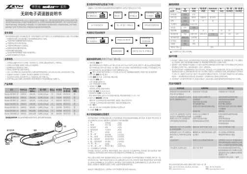
1. SMR功能: 关闭/打开通过切换电机正反向,快速停止。
出厂默认是关闭,此时1Pin信号线完全无效。
如需打开,通过App设置或遥控器编 程打开SMR功能,将3Pin信号线接入油门通道,将1Pin信号线接入接收机任意的2段开关通道,打开遥控器2段开关,此时SMR功能开启,拨动遥控器2段开关即可调整电机正反向。
警告:此功能只能在50%油门以下才有效,且只允许在飞机降落至地面使用,否则有可能引起电调烧毁!2. 刹车力度: 关闭/软/中度/最大3. 进角: 自动/低/中/高 (分别为5度/15度/25度)4. 马达方向: 正向/反向 正向:电机默认旋转方向反向:将电机旋转方向更改5. SR功能:打开/关闭 效率更高,更节能,续航时间更长6. 锂电节数: 自动/2S/3S/4S/5S/6S7. 低压保护点: 3.0V /3.2V/3.4V/3.6V例如:使用3节锂电,设定为3.0V为低电压保住值,则低压保护阈值为: 3*3.0 = 9.0V 8. 保护方式: 降低功率/立即关断 降低功率: 当达到预设的低压保护阈值时,电调减少输出功率至70% 立即关断: 当达到预设的低压保护阈值时,电调立即关断输出功率9. BEC: 5V /6V40A、50A、60A、80A、100A电调BEC电压输出可设置5V/6V 10. 加速度: 普通/柔和无刷电子调速器说明书感谢您使用中特威科技有限公司设计、制造的无刷电子调速器(ESC)。
我们强烈建议您在使用之前阅读本使用手册。
深圳市中特威科技有限公司有权不经通知变更其产品,包括其外观和性能参数及使用要求;对其产品是否适合特定用途不作任何保证、申明或承诺。
不承担因第三方产品相关修改所引起的任何责任,中特威科技有限公司也不承担因应用该产品而产生的任何责任,包括直接损失或间接损失的赔偿责任。
安全须知1. 功率输出元器件(MOSFET)选用新一代的制作工艺,发热低,瞬间承受电流大,可靠性高。
直流无刷电机驱动器说明书(1)
直流⽆刷电机驱动器说明书(1)BLDC⽆刷电机驱动器(UB510)使⽤⼿册w w w.u p u ru.c o m感谢您使⽤本产品,本使⽤操作⼿册提供UB510驱动器的配置、调试、控制相关信息。
内容包括。
l驱动器和电机的安装与检查l试转操作步骤l驱动器控制功能介绍及调整⽅法l检测与保养l异常排除本使⽤操作⼿册适合下列使⽤者参考l安装或配线⼈员l试转调机⼈员l维护或检查⼈员在使⽤之前,请您仔细详读本⼿册以确保使⽤上的正确。
此外,请将它妥善放置在安全的地点以便随时查阅。
下列在您尚未读完本⼿册时,请务必遵守事项: l安装的环境必须没有⽔⽓,腐蚀性⽓体及可燃性⽓体l接线时禁⽌将电源接⾄电机 U、V、W 的接头,⼀旦接错时将损坏驱动器 l在通电时,请勿拆解驱动器、电机或更改配线l在通电运作前,请确定紧急停机装置是否随时启动l在通电运作时,请勿接触散热⽚,以免烫伤警告:驱动器⽤于通⽤⼯业设备。
要注意下列事项:(1).为了确保正确操作,在安装、接线和操作之前必须通读操作说明书。
(2).勿改造产品。
(3).当在下列情况下使⽤本产品时,应该采取有关操作、维护和管理的相关措施。
在这种情况下,请与我们联系。
①⽤于与⽣命相关的医疗器械。
②⽤于可能造成⼈⾝安全的设备,例如:⽕车或升降机。
③⽤于可能造成社会影响的计算机系统④⽤于有关对⼈⾝安全或对公共设施有影响的其他设备。
(4).对⽤于易受震动的环境,例如:交通⼯具上操作,请咨询我们。
(5).如未按上述要求操作,造成直接或间接损失,我司将不承担相关责任。
1概述本公司研发⽣产的BLDC驱动器是⼀款⾼性能,多功能,低成本的带霍尔传感器直流⽆刷驱动器。
全数字式设计使其拥有灵活多样的输⼊控制⽅式,极⾼的调速⽐,低噪声,完善的软硬件保护功能,驱动器可通过串⼝通信接⼝与计算机相连,实现PID参数调整,保护参数,电机参数,加减速时间等参数的设置,还可进⾏IO输⼊状态,模拟量输⼊,告警状态及母线电压的监视。
HOBBYWING 30A 无刷电调使用说明书

有以下几种恢复出厂参数方法:1)利用SET键恢复出厂设置,方法如下:在油门扳机处于中点位置时,持续按住 SET 键约8秒,红绿灯同时闪烁,则表示恢复出厂设置成功,需重新上电方可运行。
2)利用LED参数设定卡恢复出厂设置:LED设定卡与电调连通后,按下“RESET”键,然后再按下“OK”保存,即可恢复出厂设置。
3)利用LCD G2设定盒恢复出厂设置:LCD G2设定盒与电调连通后,通过“ITEM”选项选到“Restore Default”项,然后按下“OK(R/P)”按键保存,即可恢复出厂设置。
4)利用OTA蓝牙模块恢复出厂设置:OTA模块与电调连通后,进入【参数设定】项目,点击“重置”按钮即可恢复出厂设置。
1. 打开遥控器,将油门通道的“D/R”、“EPA”、“ATL”等参数调到03产品特色02注意事项恢复出厂参数设定507电调状态指示灯说明08故障快速处理01声明请参照接线说明及接线图正确接线:1. 连接电机:连接有感无刷马达与无感无刷马达的方式有差异,请务必遵照如下接线方式: A. 连接有感无刷马达时:电调与马达相连有严格的线序要求,电调的#A/#B/#C必须与电机的#A/#B/#C三线严格一一对应,然后将电调与电机的感应线按照感应接口上的箭头标识对接起来。
备注: 若装上电机后,车子前进与后退反向,请更改参数项第4 项“电机转动方向”,实现电机转向调整。
B. 连接无感无刷马达时:电调与马达相连无严格的线序要求,电调的#A/#B/#C可以与电机的三线随意对接,若出现转向相反,任意交换两条马达线。
2. 连接接收机:将电调的油门控制线接入接收机的油门通道(即TH通道)。
因油门线中的红色输出6V/7.4V/8.4V电压给接收机及舵机,所以请勿给接收机额外供电,若需要额外供电,请断开电调 油门线中的红色线。
3. 连接电池:电调的输入线有极性之分,接入电池时,请确保电调的(+)极与电池的(+)极相连,(-)与(-)相连。
无刷电调说明书

提示音 1 声(短声)“嘀”—— 强制保护 2 个锂电池。 提示音 2 声(短声)“嘀”—— 强制保护 3 个锂电池。 提示音 3 声(短声)“嘀”—— 低进角设置(适用于多数高数马达)。 提示音 4 声(短声)“嘀”—— 中进角设置(适用于大部分马达)。 提示音 5 声(短声)“嘀”—— 高进角设置(适用于大扭矩低速马达)。 提示音 6 声(短声)“嘀”—— 强制保护 4 个锂电池。 提示音 7 声(短声)“嘀”—— 强制保护 5 个锂电池。 提示音 8 声(短声)“嘀”—— 强制保护 6 个锂电池。 提示音 9 声(短声)“嘀” —— 自动检测电池并设置保护值(适用于镍镉,镍氢电池)。
三, 功能设置
确定电调电池未 接上,将油门推 至全开,电调接 上电池
发出“嘀”一声 后,再 2 秒钟听 到“嘀……”的 一声长鸣的同时 将油门拉下
发出“嘀”一声 后,2 秒钟听到 “嘀……”的一 声长鸣
系统会检测油门 位置,不合适会 发出警告声音。
“嘀” “嘀”两 声后,听到音乐 声,设置完成。
听到“嘀”“嘀” “嘀” “嘀”四 后声进入功能设 置模式
选择设置某项功能,听到对应提示音的同时拉下油门推杆即可。 系统会反复循环功能设置,直到用户选择了某项功能系统才会退出功能设置回到驱动 电机状态。功能设定可能因版本不同略有差别,具体以跟随产品的使用说明为准。
一,正常启动
确定电调连接上 电机,遥控器油 门推杆在低位, 打开发射机
无刷电调使用说明书
接上电调电源, 电调系统会发出 “嘀”的提示音
约 2 秒后听到音乐声 “ ” , 表 示电调系统自检正 常,等池未 接上,将油门推 至全开,接上电 池
无刷电调使用说明书
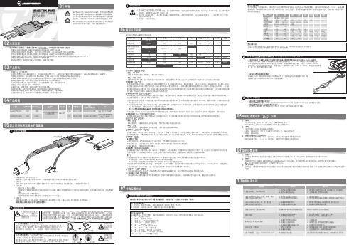
1、启动阶段1)红灯每2秒闪一次,且伴为“哔-,哔-”警示音:电调未检测到油门信号。
2)绿灯闪烁N次:上电时自动进行锂电节数检测,闪烁N次表示当前锂电为N节。
2、行驶阶段1)油门摇杆处于中点区域,红色和绿色LED均熄灭。
2)前进时,红色LED恒亮;当油门处于正向最大(100%油门)时,绿色LED也会点亮。
3)倒退时,红色LED恒亮。
3、相关保护功能触发时,LED状态含义:1)红灯持续闪烁(单闪,“☆,☆,☆”方式闪烁):电池电压太低,电调进入电池低压保护状态。
2)绿灯持续闪烁(单闪,“☆,☆,☆”方式闪烁):电调温度过高,电调进入过热保护状态。
故障现象解决方法可能原因1、电池电压没有输入到电调;1、检查电池与电调是否连接可靠,如有焊接不良,请重新焊好;上电后电机无鸣音,指示灯也未闪亮06编程设定说明08电调状态指示灯(LED)说明09保护功能说明10故障快速处理01声明Seaking Pro 120A • Seaking Pro 160A船用无刷电子调速器使用说明书· 调试请将船模架起,确保船桨不会碰到人或其他物体,以免发生安全事故。
03产品特色· 轻量化设计,适合竞赛要求。
· 出色的防水性能(160A电调采用塑封工艺,120A电调采用纳米镀膜工艺),一般情况下无需做防水处理即可直接使用(注:使用后请将电调插头吹干,以免锈蚀)。
· 内置超强开关模式BEC,持续电流达到4A,瞬间达到8A,且支持 6V和7.4V 切换,轻松驱动各种强力舵机及高压舵机。
· 采用好盈专利铜片导热技术,配合水冷模块和极低热阻的内部MOSFET,使得电调的耐流能力及可靠性大大增强。
· 使用顶级竞赛核心程序,具有一流的操控手感及丰富的调节选项,适应各种比赛环境。
· 行业首创的超速功能(即:开启Turbo进角),让马达瞬间释放更强动力,轻松超越竞争对手。
grundfos 3-25-2 无刷电子变频循环泵安装和使用说明书

GRUNDFOS INSTRUCTIONS Maintenance-free circulators with line cord and optional timer controlInstallation & operating instructionsShipment inspection. ...................................................page 2 Pre-installation checklist. .............................................page 2 Pump installation. ........................................................page 3 Electrical. .....................................................................page 5 Timer control technical data and application. .............page 5 Timer operation. ..........................................................page 6 Failure to operate. .......................................................page 7 Warranty. .....................................................................page 81. Shipment inspectionExamine the components carefully to make sure no damage has occurred to the pump during shipment. Care should be taken to ensure the pump is NOT dropped or mishandled; dropping will damage the pump.2. Pre-installation checklistBefore beginning installation procedures, the following checks should be made. They are all important for proper installation of the circulator pump.1. Uses:Model UP(S) 15 series pumps are designed to circulate water from 36°F to 230°F (UPS 15-35 from 36°F to 165°F) up to a maximum pressure of 145 PSI. If required, a 50% by volume solution of ethylene or propylene glycol and water can be used, however, a PSI decrease in pump performance may result due to an increase in the viscosity of the solution. Check with manufacturer for information regarding suitability of pumping other fluids.System applications: UP(S)15 series pumps with stainless steel or bronze volutes can be used in both open and closed systems.2. Maximum water temperature:UP(S)15 pump with line cord only. The maximum allowable water temperature is determined by the ambient or surrounding air temperature as shown in Table 2A.Table 2A – Maximum water temperatureAmbient (°F) 95 130 140 160 175 Water (°F) 230 220 210 190 175 Although the pump is designed to operate at maximum water temperature of 230°F, it is recom-mended to keep the operating temperature as lowas possible (i.e. below 140°F to avoid precipitationof calcium).Note: UP15(S) pump with timer controlmaximum water temperature: 150°F3. Inlet pressure requirementsThe amount of pressure required at the inlet of the pump is a function of the temperature of the water as shown in Table 2B.Table 2B – Inlet Pressure RequirementsWater (°F) 190 165 140 Required Inlet Pressure (ft.) 5 4.5 3(PSI) 2.2 1.9 1.3In a pressurized system, the required inlet pressure is the minimum allowable system pressure.In an open system, the required inlet pressure is the minimum distance the pump must be located below the lowest possible water level of the water source (tank, pool, etc.).3. Pump installationPosition of terminal box:Proper installation of the pump will have the terminal box located to one side of the pump or the other, with the conduit entry down. See Figure 3A.If the terminal box position needs to be changed, itis best to do so before installation. However, if the pump is already installed, ensure that the line cordis unplugged and close the isolation valves before removing the Allen screws.To change terminal box position:1. Remove the four (4) Allen screws from thepump housing and stator (4 or 5mm wrench)while supporting the stator (motor).2. Carefully separate the stator from the pumphousing and rotate it to the correct terminalbox orientation and reseat it.3. Replace the Allen screws and tightendiagonally and evenly (7 ft.-lb. torque).4. Check that the motor shaft turns freely.Remove the large screw in the middle ofthe nameplate, insert a small flat bladescrewdriver into the end of the shaft, and turngently (see fig. 7a).If the shaft does not turn easily, repeat thedisassembly/reassembly process.NOTE: UPS15-42 does not require manual t urning of shaft. Pump mounting: For indoor useArrows on the side or bottom of the pump housing indicate direction of flow through the pump. GRUNDFOS circulators can be installed in both vertical and horizontal lines. The pump must be installed with the motor shaft positioned horizontally. Under no circumstances should the pump be installed with the shaft vertical or where the shaft falls below the horizontal plane. See Figure 3B.It is recommend that isolation valves be installed on each side of the pump. If possible, do not install elbows, branch tees, and similar fittings just before or after the pump. Provide support to the pump or adjacent plumbing to reduce thermal and mechanical stress on the pump.Installation requirements1. Thoroughly clean and flush the system prior topump installation.2. Do not install the pump at the lowest point ofthe system where dirt and sediment naturallycollect.3. Install an air vent at the high point(s) of thesystem to remove accumulated air.4. Ensure that water does not enter the terminalbox during the installation process.5. (Open System) Install the pump in the supplyline; the suction side of the pump shouldbe flooded with water. Ensure that the statichead requirementfrom Table 2B is achieved.6. (Closed System) Install a safety relief valve toprotect against temperature and pressurebuild-up.7. If there are excessive suspended particles inthe water, it is recommended that a strainerand/or filter be installed and cleaned regularly.8.DO NOT START THE PUMP UNTIL THE SYSTEM HAS BEEN FILLED AND CHECKED FOR LEAKS OR OTHER POSSIBLE COMPONENT FAILURES.4. ElectricalCAUTION: Do not energize pump untilproperly installedWarning - Risk of electrical shock - This pump is supplied with a grounding conductor. To reduce the risk of electric shock, be certain that it is connected only to a properly grounded grounding type receptacle. The safe operation of this pump requires that it be grounded in accordance with the National Electrical Code and local governing codes and regulations.Electrical requirementsThe operating voltage and other electrical data are marked on the motor label. Make sure that the motor is suitable for the electrical supply on which it will be used. Electrical connectionInsert the 115V plug on the line cord from the pump intoa properly grounded 115V outlet as shown in Figure 4a.5. Timer technical dataTIMER CONTROLSupply Voltage: 115-120 VAC, 60 hertzContact Rating: 16 ampsAmbient Temperature: -4°F to 175°FMax Fluid Temperature: 150°FShortest Switching Interval: 15 minute increment Switch Modes: “Timer”, “ON” Override,“OFF” OverrideProtection: Clear plastic cover for dust andmoisture protection of the clock face.6. Timer technical applicationThe Grundfos timer control is designed only for use with specified Grundfos Series UP circulators installed in indoor hot water service systems.The timer control is designed to turn the circulator on and off at preset times, allowing the user to select operation of the circulator during high use periods of the day.7. Timer operationSetting and operating the timer control and starting the pumpFigure 6aPROGRAMMING RINGTIMING ARROWMANUAL SWITCHPROGRAMMING TABS NOTE: Before the circulator is started, the system must be filled with liquid and vented.1. Set the timer switch to the actual time byturning the programming ring in the direction ofthe arrow until the timing arrow points to theactual time on the ring.2. Switch on the power supply to the circulatorand set the manual switch to the “ON” position.The circulator will now start.3. Set the required “ON”/”OFF” times on theprogramming ring by pushing the programmingtabs either away from or toward the center ofthe ring. Tabs pushed away from the centerindicate the circulator is switched ”ON” whiletabs pushed toward the center indicate thecirculator is switched “OFF”.Figure 6b4. Set the manual switch to the “TIMER” position. The circulator will now start/stop according to the settings of the programming tabs.Figure 8a5.For continuous operation, set the manualswitch to the “ON” position. To switch thecirculator off, set the manual switch to the“OFF” position. The “ON”/”OFF” modes may beused without affecting the function of either theprogramming ring or the timer switch.6.In case of power outage the timer will not keeptime. After power has been restored, the correcttime of day must be reset by rotating theprogramming ring in the direction of the arrowuntil the timing arrow points to the actual time on the ring.8. Changing speeds with timer option • Disconnect line cord from system power.• Remove (2) timer cover screws.• Gently rotate speed selection stim to desiredspeed (see Figure 7a).• Re-install (2) timer cover screws.9. Troubleshooting When the pump is first started, the shaft may rotate slowly until water has fully penetrated the bearings. If the pump does not run, the shaft can be rotated manually. To accomplish this, switch off the electrical supply, and close the isolation valves on each side of the pump. Remove the large screw in the middle of the nameplate. Insert a small flat blade screwdriver into the end of the shaft, and gently turn until the shaft moves freely (see Figure 8a). Replace and tighten the plug. Open the isolation valves and wait 2 to 3 minutes for the system pressure to equalize before starting the pump.Figure 7aGrundfos Pumps Corporation 17100 W.118th Terrace Olathe, Kansas 66061 Telephone: (913) 227-3400 Fax: (913) 227-3500Grundfos Canada, Inc. 2941 Brighton Rd. Oakville, Ontario L6H 6C9 Telephone: (905) 829-9533 Fax: (905) 829-9512 Bombas Grundfos de Mexico, S.A. de C.V.Boulevard TLC #15, Parque Industrial Stiva AeropuertoC.P. 66600 Apodaca, N.L. Mexico Telephone: 52-81-8144-4000Fax: 52-81-8144-4010Products manufactured by GRUNDFOS PUMPS CORPORATION (GRUNDFOS) are warranted to the original user only to be free of de-fects in material and workmanship for a period of 24 months from date of installation, but not more than 30 months from date of manufacture. GRUNDFOS’ liability under this warranty shall be limited to repairing or replacing at GRUNDFOS’ option, without charge, F.O.B. GRUNDFOS’ factory or authorized service station, any product of GRUNDFOS manu-facture. GRUNDFOS will not be liable for any costs of removal, installa-tion, transportation, or any other charges which may arise in connection with a warranty claim. Products which are sold but not manufactured by GRUNDFOS are subject to the warranty provided by the manufacturer of said products and not by GRUNDFOS’ warranty. GRUNDFOS will not be liable for damage or wear to products caused by abnormal operating conditions, accident, abuse, misuse, unauthorized alteration or repair, or if the product was not installed in accordance with GRUNDFOS’ printed installation and operation instructions.To obtain service under this warranty, the defective product must be returned to the distributor or dealer of GRUNDFOS products from which it was purchased together with proof of purchase and installation date, failure date, and supporting installation data. Unless otherwise pro-vided, the distributor or dealer will contact the GRUNDFOS factory or authorized service station for instructions. Any defective product to be returned to the factory or service station must be sent freight prepaid; documentation supporting the warranty claim and/or a Return Authori-zation must be included if so instructed.GRUNDFOS WILL NOT BE LIABLE FOR ANY INCIDENTAL OR CON-SEQUENTIAL DAMAGES, LOSSES, OR EXPENSES ARISING FROM INSTALLATION, USE, OR ANY OTHER CAUSES. THERE ARE NO EXPRESS OR IMPLIED WARRANTIES, INCLUDING MERCHANT-ABILITY OR FITNESS FOR A PARTICULAR PURPOSE, WHICH EX-TEND BEYOND THOSE WARRANTIES DESCRIBED OR REFERRED TO ABOVE.Some jurisdictions do not allow the exclusion or limitation of incidental or consequential damages and some jurisdictions do not allow limita-tions on how long implied warranties may last. Therefore, the above limitations or exclusions may not apply to you. This warranty gives you specific legal rights and you may also have other rights which vary from jurisdiction to jurisdiction.L-UP-TL-018 Rev. 08.11PRINTED IN USA 10. Limited warranty。
无刷发电机的说明书

无刷发电机的说明书尊敬的用户,感谢您选择并购买我们的无刷发电机。
为了确保您正确并安全地使用该产品,我们特别为您提供以下详尽的说明书。
请您仔细阅读本说明书,并按照其中的指导进行操作和维护。
1. 产品概述无刷发电机是一种高效、低噪音的电力装置,适用于各种驱动系统。
它采用内外转子结构,无刷无触点设计,具备较长的使用寿命和稳定的电力输出。
2. 技术参数无刷发电机的技术参数如下:- 额定电压:XXXV- 额定功率:XXXW- 额定转速:XXX RPM- 最大扭矩:XXX Nm- 额定电流:XXX A请务必在使用过程中遵循以上参数,并避免超过额定数值以免造成设备损坏或人身伤害。
3. 安装与操作3.1 安装在安装无刷发电机之前,请确保断电并采取适当的防护措施。
按照以下步骤进行安装:- 将无刷发电机固定在驱动系统中,并确保连接牢固。
- 连接电源线路,确保接线正确无误,避免电气短路或漏电。
- 检查电源供应的稳定性,确保电压和频率满足要求。
3.2 操作- 在启动操作之前,请确认连接正确,并确保工作环境清洁、通风良好。
- 建议在无刷发电机正常运行前,逐步增加转速和负载,以避免过载损坏设备。
- 避免在恶劣的工作环境下使用无刷发电机,如高温、潮湿或腐蚀性气体环境。
- 当发现异常声音、震动或其他异常情况时,请立即停止使用,并检查设备是否有故障。
4. 维护与保养- 定期清洁无刷发电机外壳和散热器,确保散热良好,并避免灰尘和杂物积累。
- 检查各连接点,确保紧固件处于正常状态,避免松动造成的电气接触不良。
- 请勿私自拆卸或修改无刷发电机内部零部件,以免损坏设备和导致安全隐患。
- 如需维修或更换零部件,请联系我们的售后服务,遵循专业技术人员的指导操作。
5. 安全注意事项- 在使用过程中,请勿触摸无刷发电机运行时的旋转部件,以免造成伤害。
- 禁止将无刷发电机浸入液体中,避免发生触电或设备损坏。
- 请勿长时间过载工作,避免发电机过热和设备损坏。
霍尼韦尔XERUN AXE无刷系统用户手册说明书
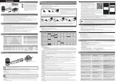
01Disclaimer03Features02Warnings04Specifications05ConnectionsThank you for purchasing the HOBBYWING’s XERUN AXE BrushlessSystem! Brushless power systems can be very dangerous. Anyimproper use may cause personal injury and damage to the product• Apply FOC(Field Oriented Control) driving mode to the power system of rock crawler. The low speed torque Is very strong, it is better than ordinary sensored brushless power system oreven better than the brushed power system.• The chip-type magnetic encoder inside the motor guarantees consistency between three phases’ signals and always outputs the pure and precise signals indicating the rotor position.system from water or dust. Damage to the vehicle caused by water, mud, or conditions should be monitored closely when running in muddy, wet, or adverse conditions.• Intelligent torque output & speed closed-loop control for easy control, and consistent motor RPM under all loads.• The adjustable drag brake & drag brake rate control with the maximum drag brake of up to 200% (that’s nearly twice the drag brake of standard brushless power systems) can provideunprecedented parking capacity on slopes, with no jerky stops.• The innovative built-in Bluetooth connectivity allows users to read ESC data or update ESC firmware via a smart phone (installed with the HW LINK app).• Multiple protections: low-voltage cutoff, thermal, fail safe (throttle signal loss), motor lock-up, over current, and battery reversal.• It supports dual operation mode, not only classic "Forward and Reverse (rock crawler)" mode, but also "Forward/Reversewith brake (normal)" mode.1. Cooling Fan Installation (Optional)When pairing the ESC with a 550 motor, we recommend installing the matching cooling fan. The cooling fan can be powered by the receiver.2. Motor WiringThe XERUN AXE brushless ESC only supports the XERUN AXE series of FOC brushless motors. The Axe ESC it cannot be paired with any other type of motor. The Axe Motor, cannot beused with any other type of ESC.There is strict wiring order from the ESC to the motor, the three A/B/C ESC wires must connect to the three A/B/C motor wires correspondingly. Next, connect the ESC sensor wire to themotor sensor wire. Never change the order of your motor wires or damage will occur.3. Receiver WiringThe throttle control cable on the ESC has to be plugged into the throttle (TH) channel on the receiver. The throttle control cable (the Red wire) provides an output voltage of 6V/7.4V tothe receiver and steering servo, hence, no separate battery can be connected to the receiver. Improper wiring of any external BEC, or battery pack will result in damage to your ESC.4. Battery WiringProper polarity is essential. Please ensure positive (+) connects to positive (+), and negative (-) connects to negative (-) when plugging in the battery! When reverse polarity is applied tothe ESC from the battery, it will not function.21) Power ON/OFF:(Start with the ESC turned off), press the ON/OFF button to turn on the ESC;(start with the ESC turned on) press and hold the ON/OFF button to turn off the ESC.2) Warning Tones: Turn on the ESC in the normal way (that is to turn it on without holding the SET button); the motor will beep the number of LiPo cells you have plugged in.For example, 3 beeps indicate a 3S LiPo.Programmable Items31. Running ModeOption 1: Forward and ReverseThis mode is often used by special vehicles (rock crawler). It adopts the “SINGLE-CLICK” method. The vehicle will reverse immediately when you push the throttle trigger forward.Option 2: Forward/Reverse with BrakeThis mode provides the braking function, it’s usually for training. “Forward/Reverse with Brake” mode adopted the “DOUBLE-CLICK” method, that is your vehicle only brakes (won’t reverse)when the 1st time you push the throttle trigger forward (away from you) (1st push). If the motor stops when you quickly release the throttle trigger and thenre-push the trigger quickly (2ndpush), the vehicle will reverse. If the motor does not stop, then your vehicle won’t reverse but brake, you need to push the throttle trigger one more time. The vehicle only reverses after themotor stops. This method is for preventing vehicle from being accidentally reversed.2. Cutoff VoltageLow Voltage Cutoff for LiPo Protection. This item is mainly for preventing the LiPo pack from over-discharge. If the low-voltage cutoff protection is enabled, the ESC will monitor the batteryvoltage all the time and gradually reduce the output to 50% (in 3 seconds) and cut it off 10 seconds later when the voltage goes below the cutoff threshold. The Red LED will flash a singleflash that repeats (☆-, ☆-, ☆-....) when the ESC enters the low-voltage cutoff protection. The ESC will not cut off the power when the voltage is low if the low-voltage cutoff protection isdisabled. We don’t recommend setting the “Cutoff Voltage” to “Disabled” when using a LiPo pack, otherwise, the battery will be damaged due to over-discharge.• NiMH - For a NiMH pack, we recommend setting this item to “Disabled”.• Voltage - The specific voltage values correspond to “Low/Intermediate/high” are 3.0V/3.2V/3.4V per cell. Please note, due to a number of variables you may not see exactly these samevoltage values.3. RPM/Throttle MatchingThe speed/RPM will change when the vehicle encounters obstacles or terrain changes based on the loads (on the vehicle), so changing this setting (with the throttle input remainsunchanged) can change the resistance to maintain the speed/RPM.With the throttle input remains unchanged, setting this item to “Low” allows you to have the kind of feeling that a brushed motor will bring you, then the speed/RPM will be significantlyinfluenced by the resistance change; setting it to “High” allows you to have a remarkable feeling of speed-governing, that is the speed will change seldom due to the resistance change andthe speed/RPM remains almost unchanged.In simple terms, set it to “Low” if you like the feeling that a brushed motor will bring you or set it to “High” if you like a more stable speed/RPM when the throttle input remainsunchanged, (it’s “Intermediate” by default, ) so please set it as per your preference.This setting is only valid in "Forward and Reverse (rock crawler)" mode!4. Max. Forward ForceIt’s the force when throttle trigger is at the full throttle position. It’s adjustable among 25%, 37.5%, 50%, 62.5%, 75%, 87.5% and 100% (by default). You can lower down the value forbetter driving feel/control when you drive a crawler (simulation model) over difficult terrains (and don’t have any requirement against the maximum speed).5. Max. Reverse ForceThe reverse force of the value will determine its speed. For the safety of your vehicle, we recommend using a low amount.6. Turbo TimingThis item is adjustable from 0 degree to 10 degrees, the corresponding turbo timing (you set) will initiate at full throttle. It’s usually activated on long straightaway and makes the motorunleash its maximum potential. Turbo timing adds “RPM” at full throttle.7. Turbo DelayWhen “TURBO DELAY” is set to “INSTANT”, the Turbo Timing will be activated when throttle trigger is moved to the full throttle position. When other value is applied, you will need to holdthe throttle trigger at the full throttle position (as you set) till the Turbo Timing initiates.8. Drag Brake ForceIt is the braking power produced when the throttle is at the neutral position. (Attention! Drag brake will consume more power and heat will be increased, apply it cautiously.). Higher dragbrake means stronger hold or hill brakes.This setting is only valid in "Forward and Reverse (rock crawler)" mode!9. Drag Brake RateIt’s the rate at which the drag brake increases to the preset value. This feature slows down how rapidly the ESC applies brakes. Lower values are slower and prevent sudden stops or jerkystopping movements. You can choose the drag brake rate from level 1 (very soft) to level 9 (very aggressive).In Auto mode, the ESC adjusts the brag brake rate automatically as per the current speed. The higher the current speed, the lower the drag brake rate (when releasing the throttle trigger tothe neutral position); the lower the current speed, the higher the drag brake rate. It can not only help prevent vehicle from flipping over or the drivetrain from damage due to the rapidintervention of drag brake when driving at a high speed but also guarantee the sensitive control feel when driving at a low speed. This setting is only valid in "Forward and Reverse(rock crawler)" mode!10. Neutral RangeAs not all transmitters have the same stability at “neutral position”, please adjust this parameter as per your preference. You can adjust to a bigger value when this happens. The neutralrange is the “dead zone” or “dead band” of the throttle/brakes. If you notice inconsistent drag brakes, you would increase your neutral range value.11. Start Mode/(Punch)You can choose the punch from level 1 (very soft) to level 9 (very aggressive). This feature is very useful for preventing tires from slipping during the starting-up process. In addition, “level7” and “level 9” have strict requirement on battery’s discharge capability. It may affect the starting-up if the battery discharges poorly and cannot provide large current in a short time. Thecar stutters or suddenly loses power in the starting-up process indicating the battery’s discharge capability is not good, and you need to reduce the punch or reduce the pinion gear size.12. BEC VoltageOption 1: 6.0VIt’s applicable to ordinary servos. Do not use this option with high voltage servos; otherwise your servos may not function normally due to insufficient voltage.Option 2: 7.4VIt’s applicable to high voltage servos. Do not use this option with ordinary servos; otherwise your servos may be burnt due to high voltage.13.Motor RotationThis feature allows the changing of the motor’s forward direction. To check, look at the motor with the shaft facing you. If the motor spins counter clockwise if this item is set to CCW; themotor spins clockwise if set to CW. The drive train of your chassis will determine what direction motor you should use. Some vehicles use normal or CCW rotation, other vehicles use CW orbackwards rotation motors.ESC Programming & Firmware Upgrade - The Axe ESC is Only Adjustable using the HW Link App and a Bluetooth enabled Smart Phone41) Program your ESC with a smart phone (installed with the HW LINK app)• Download and install the Hobbywing’s official app “HW LINK” on your smartphone. For smart phones with the iOS operating system, please search“Hobbywing” in the App Store; for smart phones with the Android operatingsystem, search “Hobbywing” in the Google Play or download it from our websiteor scan the following QR code to download it.• Connect a battery to the ESC and turn it on, then open the Hobbywing officialapp“HW LINK” on your smart phone.It will ask if you want to connect “Bluetooth” or “WiFi” the first time when youopen the app; at this point, please select “Bluetooth”. You need to change theconnection to “Bluetooth” after using the “WiFi” connection, you can click“Settings” (on the home page) and then “Select the connecting mode” to change the connection.A list of Bluetooth devices will pop out when you click the ESC icon on the upper right corner, then select the ESC youwant to program to establish the Bluetooth connection between the ESC and smart phone. (Note: the default name &password of the Bluetooth device are HW_BLE**** & 888888 respectively.)• Click “Parameters” (on the home page) to adjust the ESC parameters, click the ESC icon on the upper right corner todisconnect the Bluetooth connection between the ESC and smart phone after completing and saving the adjustments.2) Firmware Upgrade with a smart phone (installed with the HW LINK app)• Download and install the Hobbywing’s official app “HW LINK” on your smart phone.• As you enter the app, click Settings→About→Check for updates to ensure that the database and software version of your ESC are the latest.• Connect a battery to the ESC and then turn it on, open the “HW LINK” app on your smart phone, a list of Bluetooth devices will pop out when you click the ESC icon on the upper rightcorner, then select the ESC (Bluetooth device) you want to program to establish the Bluetooth connection between the ESC and smart phone.(Note: the default name & password of the Bluetooth device are HW_BLE**** & 888888 respectively.)• Click “Firmware upgrade” and then “Select the target version” to select the firmware version you need, and then click “Update” to upgrade your ESC. After the upgrade, you can adjustthe parameters via “Parameters” and click the ESC icon on the upper right corner to disconnect the Bluetooth connection between the ESC and smart phone after saving the adjustments.07Explanations for Different Status LEDs08Trouble ShootingFactory Reset5• Restore the default values (ESC parameters & Info about the Bluetooth module) with the SET buttonTurn on the ESC, press and hold the Set button for over 3 seconds.Pressing and holding the SET button for over 3 seconds at any time when the throttle stick is at the neutral position (except during the ESC calibration or programming), canfactory reset your ESC. The Red & Green LEDs flash at the same time indicating the factory reset is successful. The default values only take effect after you turn the ESC off andthen on again.Attention! This method will also factory reset the Bluetooth device.• Restore the default values (only the ESC parameters) with a smart phone (installed with the HW LINK app)After entering the app and establishing the Bluetooth connection between the ESC and smart phone, click “Factory Reset” in “Parameters” to factory reset your ESC.After that, please re-calibrate the throttle range.Automatic Motor Pairing (Optional)6You must do the “automatic motor pairing” (as explained below) when any of the following situations occurs:1) Updated the ESC firmware,2) Issues like loose rear endplate, severe impact, or abnormal heat (during the operation) abnormal power output occurs to the motor,Steps of “Automatic Motor Pairing”Step1: Unplug the throttle wire from the receiver, and then remove the pinion gear (or you can hold the vehicle in the air and remove the wheels, but the effect won’t be that good);Step2: Connect a battery (to the ESC), turn it on, press and hold the SET button for 3 seconds after it completes the self test to enter the “automatic motor pairing”, the motorwill spin a while during the process.Step3: The ESC will automatically re-start and beep out the number of the LiPo cells you’ve plugged in after the pairing completes, after that, please re-plug the throttle wire intothe receiver, and then the power system will be ready.1. During the Starting-up Process• The Red LED keeps flashing rapidly indicating the ESC doesn’t detect any throttle signal or the neutral throttle value stored on your ESC may be different from the current value storedon the transmitter. - Redo the ESC calibration Process if your ESC is flashing and not working.• The Green LED flashes “N/ (number of)” times indicating the number of LiPo cells you have plugged in.2. In Operation - What lights you should see.• The Red & Green LEDs go out when the throttle trigger is in throttle neutral zone.• The Red LED turns on solid when your vehicle runs forward. The Green LED will also come on solid when pulling the throttle trigger to the full (100%) throttle endpoint and setting the“Max. Forward Force” to 100%.• The Red LED turns on solid when you brake the vehicle, the Green LED will also come on solid when pushing the throttle trigger to the full brake endpoint and setting the“Max. Reverse Force” to 100%.3. Error or Warning LED CodesN• The Red LED flashes a short, single flash that repeats (☆, ☆, ☆) indicating the low voltage cutoff protection is activated.• The Green LED flashes a short, single flash that repeats (☆, ☆, ☆) indicating the ESC thermal protection is activated.• The Green LED flashes a short, double flash that repeats (☆☆, ☆☆, ☆☆) indicating the motor thermal protection is activated.• The Green and Red LEDs flash a short, double flash that repeats (☆☆, ☆☆, ☆☆) indicating the power system stops functioning due to “sensor issue”. In that case, please check ifthe ESC sensor wire has been firmly connected to the motor sensor wire before resuming the operation.• Ensure all wires and connections are well insulated before connecting the ESC to related devices, as short circuit will damage your ESC.• Ensure all devices are well connected to prevent poor connection that may cause your vehicle to lose control or other unpredictable issues such as damage to the device.• Read through the manuals of all power devices and chassis and ensure the power configuration is correct before using this unit.• The ESC must be Calibrated or setup to your radio system before normal operation.USER MANUALXERUN AXE R2 Brushless SystemNote: those black-and-white options are default values.20200924· 更新过程中,请确保网络环境稳定,不要在强干扰区域操作。
Flycolor 40A 无刷电子调速器 使用说明书

车用无刷电子调速器● 支持近距离监测和记录实时数据,方便了解运行状态(需单独购买Flycolor WiFi 模块)。
电调第一次使用或遥控器修改过油门中点、ATL 、EPA 等参数,均需重设油门行程。
遥控器ABS 功能必须设置为OFF ,遥控器油门通道方向设置为“R E V ”,油门微调设置为“0”,油门通道的EPA/ATL 正反向均设置为100%(最大)。
不然可能会导致无法使用或误动作。
电调接上电池,开启遥控器,持续按住“Power/PRG ”键不放;松开"Power/PRG "按键后,红灯停止闪烁,表示进入遥控器油门行程设定;1.3.1)油门中点:油门摇杆置于中点位置,按一下“Power/PRG”键,绿灯闪烁一次,电机鸣叫一次,表示中点油门被存储;2)油门正向最高点:油门摇杆打到正向最高点位置,按一下“Power/PRG” 键,绿灯闪烁两次,电机鸣叫两次,表示正向最大油门被存储;3)油门反向最高点:油门摇杆打到反向最高点位置,按一下“Power/PRG” 键,绿灯闪烁三次,电机鸣叫三次,表示反向最大油门被存储;4.5.油门摇杆回到中点位置,绿灯闪烁N 次指示N 节电池数,然后红色LED 开始持续闪烁(如是有感电机则红色LED 闪烁,绿色LED 常亮),表示此时需要设定三个点:05 编程选项及说明1、运行模式:●正转带刹车:只能前进,油门反向时为刹车,无倒车,该模式主要用于竞赛。
●正反转带刹车:有倒车功能,当油门从正向推到反向区域时,车子处于刹车状态,油门必须回中且电机停止运转后,第二次推至反向区域才倒车。
●直接正反转:当油门从中点区域推至反向区域时,电机立即倒车,该模式一般用于攀岩车等特种车辆。
2、油门中立点区域:6%、9%、12%。
有些遥控器中点位置容易漂移,如果漂移,请把区域值设置更大;也可根据个人喜好或手感实验后选择。
3、初始刹车力度:最小刹车力度,是指在刹车初始位置时作用在电机上的刹车力。
0535无刷角磨机控制板的使用说明书

0535无刷角磨机控制板的使用说明书1.作业前的检查应符合下列要求:1)外壳、手柄不出现裂缝、破损;2)电缆软线及插头等完好无损,开关动作正常,保护接零连接正确,牢固可靠。
移动工具时切勿用手提拉电源线的方法,亦不得用手拉电源线的方式将工具从插座拔下的方法,这样做可能造成电源线折断,产生危险;3)各部防护罩齐全牢固,电气保护装置可靠。
严禁在拆除砂轮防护罩的情况下使用磨光机;2.使用前,要确认工具所接电源电压必须符合铭牌的规定值,接通电源时,工具开关应是于“断开”位置。
机具启动后,应空载运转,应检查并确认机具联动灵活无阻。
再接触被加工的工件,严禁在工具已经与工件接触的状态下直接启动工具进行作业。
作业时,加力应平稳,不得用力过猛;3.使用砂轮的机具,应检查砂轮与接盘间的软垫并安装稳固,螺帽不得过紧,凡受潮、变形、裂纹、破碎、磕边缺口或接触过油、碱类的砂轮均不得使用,并不得将受潮的砂轮片自行烘干使用;4.砂轮应选用增强纤维树脂型,其安全线速度不得小于80m/s。
配用的电缆与插头应具有加强绝缘性能,并不得任意更换;5.磨削作业时,应使砂轮与工作面保持15-30°的倾斜位置;切削作业时,砂轮不得倾斜,并不得横向摆动;6.严禁超载使用。
作业中应注意音响及温升,发现异常应立即停机检查。
在作业时间过长,机具温升超过60℃时,应停机,自然冷却后再行作业;7.作业中,不得用手触摸刃具、模具和砂轮,发现其有磨钝、破损情况时,应立即停机修整或更换,然后再继续进行作业。
工具出现故障需检修时,或需要更换任何零件时,均应在插头自电源插座拔下的状态进行;8.机具转动时,不得撒手不管。
使用中应自始至终戴防护目镜和穿着合适的工作服。
晓飞无刷电机-视频发射器使用说明书

视频发射器使用说明书
1、功率调节
长按功率调节按键切换图传发射功率,从0功率调整至25mW需长按10秒,表示解锁功率输出并启动25mW输出功率,从25mW调整至200mW 需长按2秒,每次按下以后功率只切换一次,松开按键再次操作可继续切换,功率会在0—25mW—200mW之间依次循环,设置为0mw时功率 指示灯全部熄灭,设置为25mW时功率指示灯亮绿色,设置为200mW时功率指示灯亮红色。
2、频点调节(频组-频道构成频点)
频点会显示在图传板上的数码显示管,显示为C8则对应表格内的频率为5725MHz;
频组调节:长按频率调节按键2秒进入频率组设置,进入设置后数码管开始闪烁,短按按键更改频率组,频率组从A到F依次循环,选择相应的频率 组后,长按频率调节按键2秒保存并退出频率组设置;
频道调节:长按频率调节按键2秒进入频道设置,进入设置后数码管开始闪烁,短按按键更改频道,频道从1到8循环,选择相应的频道后,长按频 率调节按键2S保存并退出频道设置;
3、频率组与频道调节是轮循方式,即调节完频率组后为频道调节,调节完频道后为频率组调节如此循环。
4、频点-频率对应表
02产品规格
04参数调节
03图传布局及接口定义
型号发射频率发射功率 5.8GHz 视频发射器5.3GHz-5.9GHz 0 / 25mW / 200mW
70mA / 100mA / 250mA @ 12V
SMA 母头SMA 公头7-25V 36x36mm 30.5x30.5mm
*D组与F组为比赛频率组,可实现同组下8个频道同时使用互不干扰。
摄像头输入
电源输入
摄像头5V/12V 电压选择OSD 短接焊点
Video
20170919。
JUSTOCK Handout Spec 车用有感无刷电机 使用说明书
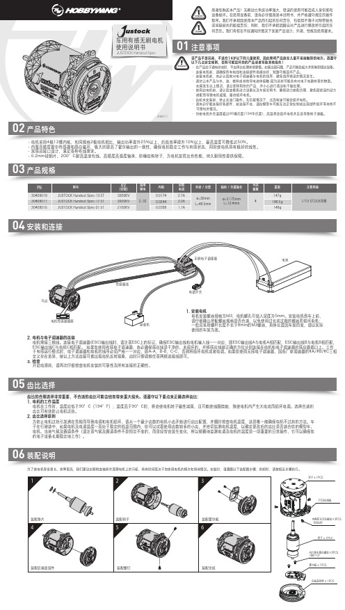
JUSTOCK Handout Spec车用有感无刷电机使用说明书该产品不是玩具,不适合14岁以下的儿童使用,因此需将产品放在儿童不易接触到的地方。
请遵守以下几点安全规则,否则可能毁坏您的产品或者导致其他损失!· 在产品处于通电状态时,不应再去处理其他事情。
如果出现问题,产品可能会起火并影响到周边设备。
· 连接电机前,请确保所有电线和连接部件绝缘良好,短路可能毁坏产品。
· 连接电机前,务必认真核对电子调速器与电机的线序,避免线序错误的情况发生。
可预知的情况。
· 勿使电机外壳温度超过90摄氏度(194华氏度),高温将会毁坏电机并且会导致转子退磁。
01注意事项02产品特色05齿比选择06装配说明为了使电机寿命更长、效率更高,我们建议定期检查轴承并清理电机上的污垢,具体时间取决于您使用电机的频次和场地情况。
安装时,请遵循以下装配图步骤;拆卸时,请按相反步骤执行。
KV (空载)适用锂电内阻JUSTOCK Handout Spec-13.5T JUSTOCK Handout Spec-17.5T JUSTOCK Handout Spec-21.5T3200KV 2600KV 2100KV0.01740.02440.03982~3S 齿比的合理选择非常重要,不合适的齿比可能会给您带来重大损失。
请遵守以下要点来正确选择齿比:1. 电机的工作温度电机在工作时,温度应低于90°C(194°F);温度高于90°C时,将会使电机转子磁性减弱,且可能使线圈烧熔,致使电机内产生大电流而损坏电调。
选择合适的 齿比可有效防止电机过热。
2. 齿比选择原则为防止电机过热引发潜在危险而导致电调和电机损坏,请从一个最少齿数的电机小齿开始进行齿比配置,并随时检查电机温度,这是唯一能确保电机不过热的方法。
车 子在行驶途中,如果电机及电调温度一直处于稳定的低温范围内,您可以试着使用齿数较多的小齿,并密切监测电机温度,以确定更改后的齿比是否适合您的模型车、 电机、当地气候及赛道条件(请注意气候及赛道条件不是恒定不变的,而是经常会发生变化,所以频繁地监测电调及电机的温度是一项重要的日常操作,它可以确保您 的电子设备长期稳定地工作)。
- 1、下载文档前请自行甄别文档内容的完整性,平台不提供额外的编辑、内容补充、找答案等附加服务。
- 2、"仅部分预览"的文档,不可在线预览部分如存在完整性等问题,可反馈申请退款(可完整预览的文档不适用该条件!)。
- 3、如文档侵犯您的权益,请联系客服反馈,我们会尽快为您处理(人工客服工作时间:9:00-18:30)。
DA VR-A1/A2、D1发电机励磁调节器使用维护说明书山东济南发电设备厂目录1、总述 (4)1.1介绍 (4)1.2用途 (4)1.3使用环境 (5)1.4安全规则 (5)1.5型号说明 (6)1.6适用范围 (6)1.7柜体尺寸 (6)1.8供货范围 (6)1.9技术参数及性能指标 (6)2、系统简述 (7)2.1 主电路 (8)2.2 励磁电源部分 (8)2.3 起励及灭磁部分 (8)3、调节控制部分 (9)3.1控制模块介绍 (10)3.1.1硬件 (10)3.1.2设备连接 (12)3.1.3数字量输入 (15)3.1.4数字量输出 (17)3.1.5模拟量输入 (18)3.1.6模拟量输出 (19)3.2 软件 (20)3.2.1运行状态 (20)3.2.2参数说明 (21)3.3 操作 (29)3.3.1控制模块的操作 (29)3.3.1.1键盘 (29)3.3.1.2显示 (29)3.3.1.3参数设定示例 (30)3.3.1.4显示屏上的菜单结构 (32)3.3.1.5显示屏上的错误信息 (36)3.3.2 PC工具 (37)3.3.2.1用PC工具进行操作 (38)3.3.2.2用PC工具设定参数示例 (39)3.3.2.3 PC工具的菜单结构 (41)3.3.2.4存储参数文件 (50)3.3.2.5波形测定 (51)3.3.2.6在读取控制模块内参数时的错误信息 (54)3.4 调试 (54)3.4.1 安全规则 (54)3.4.2 设定目标值 (55)3.4.3 机组静止时的调试试验 (60)3.4.4 机组运行时的调试试验 (61)3.5 维护和故障 (63)3.5.1维护 (63)3.5.2故障排除 (63)3.5.3 维修 (65)3.6 附录 (66)3.6.1 参数设定和缺省值 (66)4、DA VR—A1励磁调节器使用操作步骤 (71)5、用户订货须知 (72)1.总述1.1介绍随着现代科学技术的发展以及电站设备自动化水平的提高,电厂要求实现无人值班或少人值班,提高电厂发电工作效率,减少维护工作量,提高系统的可靠性和稳定性。
励磁控制系统正是实现这些要求的关键设备,近几年,各个励磁调节器生产厂家也在着力提高励磁调节系统的技术含量。
1.2用途本使用说明书为DA VR-A1/A2、D1发电机励磁调节器的正确使用、正常维护、以及安装调试提供所有必要的技术数据及信息。
本手册的使用人员应具备基本的电机工程系统知识。
当本系统第一次投入运行或需要确定故障时,还需要一些特殊知识及经验。
使用本手册时,请同时参考特定系统的原理图。
手册中的介绍主要是针对特定系统而言的。
各功能描述只对所提供特定型号的系统有效。
当发生故障时,本手册可以用来帮助确定故障范围。
1.3使用环境1、海拔不高于2000米。
2、空气相对湿度不大于85%(当介质温度在200C时)。
3、周围环境温度为-30~400C。
4、无剧烈振动及强力冲击、颠簸的地方。
5、无腐蚀性气体及导电尘埃的环境。
1.4安全规则为了保证运行人员安全,在门上和特殊之处贴了警告标志。
用于一般性警告,用于高压危险警告。
在操作开关之前,运行人员必须确认设备是安全可靠可以操作的。
注意:“注意”表明这部分规则不被遵守时可能导致元件或设备损坏。
备注:“备注”表明这部分为附加信息,这些信息必须予以考虑以避免故障发生。
运行人员要求·运行人员首先须仔细阅读本手册。
·运行人员须知道励磁对电网的影响(如磁场电流、发电机电压、无功功率等)。
·无论是就地控制或远方控制,运行人员须熟知控制单元,操作和报警指示。
·运行人员也须懂得操作励磁系统所产生的结果,能通晓励磁系统的报警信息。
1.5 型号说明DA VR—A1 表示:数字式自动电压调节器—无刷励磁方式DA VR—A2表示:数字式自动电压调节器—双微机无刷励磁方式DA VR—D1 表示:数字式自动电压调节器—直流励磁机励磁方式1.6适用范围本调节器适用于100MW以下由交、直流励磁机提供励磁功率的汽轮发电机组。
1.7柜体尺寸励磁调节器柜体尺寸(单位:mm)800×600×22601.8供货范围调节柜一面高压励磁变压器(无刷励磁用)一台电压互感器两只电流互感器一只1.9技术参数及性能指标主要技术参数及性能指标符合或优于GB7409—1997和电力部有关标准调节精度:<0.1%额定电压调节范围:0—150%额定电压强行励磁: 1.6—2倍,≥10秒调差范围:-20%—+20%,无级频率特性:频率每变1Hz端电压变化<0.1%起励:软起励,可做到无超调无振荡空载10%阶跃:超调量<5%,振荡次数<3,调节时间<5S 辅助电源:三相交流输入:9—250V单相交流输入:50—250V直流输入电压:18—300V最大功率消耗:25W功率电压:交流输入:0—250V直流输入:0—300V频率范围:40—600Hz测量输入:发电机三相电压:最大250V发电机单相电流:5A励磁输出:连续工作电流:15A DC过载(10S最大):30A DC过载(4分钟最大):20A DC串行接口:RS—232、RS—4852. 系统简述本调节器适用于机组容量为100MW以下的带有励磁机的汽轮发电机组,自动电压调节器以发电机机端电压为调节对象,根据电网电压变化,自动调节发电机输出无功功率,从而达到恒机端电压运行目的。
为了增加励磁调节器的安全冗余度以及用户作机组试验方便,设计了自动励磁电流控制方式,控制发电机的磁场电流为恒定值。
在此两种基本的控制方式之外,又设计了恒功率因数控制、恒无功控制、开环控制方式,同时为使发电机工作于安全范围之内,增加了各种限制器,如最大励磁电流限制、定子电流限制、低励限制、最小励磁电流限制、V/Hz限制等附加控制功能。
为了使操作人员及时了解设备工作情况,DA VR系列励磁调节器还提供了下述报警信号:电源故障、起励失败、误强励、误强减、限制器故障等,便于运行人员及时处理问题。
2.1主电路DA VR-A1/A2、D1数字型发电机励磁调节器控制交流励磁机或直流励磁机的励磁电流,间接调节发电机励磁绕组的励磁电流,控制发电机组的机端电压。
励磁功率电源通过励磁变压器取自发电机机端或直流励磁机电枢电压,由不可控整流桥及IGBT半导体管提供直流励磁电流,实现发电机组的自励。
2.2励磁电源部分汽轮发电机组为交流励磁机无刷励磁方式时,励磁电源通过柜体内的隔离变压器T03取自发电机机端的高压励磁变压器T02。
汽轮发电机组为直流励磁机励磁方式时,励磁电源取自直流励磁机电枢。
2.3起励及灭磁部分调节器内部设置了厂用直流电起励回路,可满足他励起励要求。
灭磁时用Q02灭磁开关将励磁机励磁绕组磁场能量通过灭磁电阻R01消耗掉,达到灭磁目的。
当机组为直流励磁机励磁方式时,发电机磁场能量通过灭磁开关MK和灭磁电阻Rfm消耗掉。
3.调节控制部分调节与控制部分选用瑞士ABB工业公司生产的UNITROL®1000 控制模块。
此模块具有完善的调节控制功能,可根据机组不同的运行工况,为机组提供相应的励磁电流。
控制模块为双通道结构,即自动电压调节控制通道和励磁电流手动调节控制通道。
正常运行时,自动电压调节控制通道一般为工作通道,这时励磁电流手动调节控制通道处于热备用状态,跟踪自动通道工作情况,以便随时无扰动切换。
自动电压调节通道为PID控制规律,控制发电机机端电压为恒定值,而手动调节通道为PI控制规律,控制励磁电流为恒定值。
除此之外,还有恒功率因数调节、恒无功调节和开环调节以适应不同的运行要求。
为了保证机组的正常运行,在上述基本控制规律的基础上还有下述附加限制保护功能:软起励V/Hz限制器最小励磁电流限制器最小无功电流限制器三段延时最大励磁电流限制器内部自动检测系统硬件结构上,UNITROL®1000控制模块备有非常灵活的输入输出接口,用户可根据实际需要自由设定输入输出端口。
*3路模拟量输入*2路模拟量输出*4路数字量输入*4路数字量输出4路数字输出量也可以根据需要重新定义为数字量输入。
一个串行口RS—485用于几个UNITROL®1000之间的联接以构筑备用系统或用于几台发电机并列运行时的无功电流补偿。
一个串行口RS—232接口用于与PC机联接。
所有参数可简单地通过控制模块上的按键在设备上直接进行设定,不需任何外加的设备,也可通过基于WINDOWS的PC软件进行设定,并进行参数的调整和优化。
3.1控制模块介绍3.1.1硬件结构:整个设备装在一个铝制壳体内,有散热孔。
连接端子集中安放在主机板前面,一层挨一层。
功率模块:功率部分装有一只IGBT半导体管,输出电压平均值总是正值。
输出有限流保护和短路保护。
控制元件:操作按键、显示屏和RS—232母接口都装在表面。
控制键和接口:控制模块操作四个按键和四行状态显示可有效的满足所有操作。
所有的参数设定可在控制模块上直接实现而不需其他附加设备。
*输入和输出变量定义*参数设定*重要测量数值显示与PC机的接口参数设定和工作状态选择也可通过界面友好的PC工具实现。
9针连接电缆,sub—D接头(母)*输入输出变量定义*参数设定*图形功能(示波器,出力图)*重要测量参数显示*参数文件上载或下载3.1.2设备连接注意:对于所有数字量输入和数字量输出,内部24V电源可带最大负载电流300mA。
3.1.3数字量输入数字量输入端子DIO1到4,DI5到8,(DI9到14)可以根据需要自由设定。
数字量输入电平设定范围:0—28VDC数字量输入极性软件设定3.1.4数字量输出*)见3.2.2参数说明部分数字量输出端子DIO1到4,可以自由设定.3.1.5模拟量输入模拟量输入端子AI1—3,可以根据需要自由设定模拟量输入一个模拟量信号产生两个数字量信号3.1.6模拟量输出模拟量输出端子AO1—2,可以根据需要自由设定模拟量输出电平注意:Ie 0%必须小于Ie 100%励磁电流PWM输出:当用10为二进制的分辨率时,电压范围为—10V到10V。
3.2软件3.2.1运行状态自动电压调节(Auto状态)根据同步电机端电压调节。
备注:电流测量用于无功补偿。
手动控制调节励磁机励磁电流。
备注:限制器不起作用。
恒功率因数或恒无功调节(PF,Var状态)根据同步电机功率因数或无功功率调节。
开环控制手动控制时,输出定值信号备注:限制器不起作用。
电压下降补偿和无功功率分配(VDC)为了使并联运行的发电机组按比例分配无功,UN1TROL®1000有一个特殊的调节方式,叫电压下降补偿控制。
各机组的控制模块通过RS—485连接在一起。
