NX8571SC687-BA中文资料
NI 67xx 引脚布局标签-SCB-68A说明书
NOTE TO USERSNI 67xx Pinout Labels for the SCB-68AAnalog Output Modules/Devices Using the 68-Pin Shielded Connector BlockIf you are using an NI 67xx (formerly referred to as AO Series) analog output device or module with the SCB-68A, you can print and attach a connector-specific pinout label to the cover of the connector block for easy connection reference. This document provides labels for the following models:•NI 6703•NI 6704•NI 6711•NI 6713•NI 6715•NI 6722•NI 6723•NI 6731•NI 6733•NI 6738•NI 67392||NI 67xx Pinout Labels for the SCB-68A Note To UsersNI 67xx Pinout Labels for the SCB-68A Note To Users|© National Instruments|3Use the following label if you are connecting the SCB-68A to the NI6711/6731 models.Figure 3. NI 6711/67314||NI 67xx Pinout Labels for the SCB-68A Note To UsersUse the following label if you are connecting the SCB-68A to Connector0 of theNI6713/6722/6723/6733 models.Figure 4. NI 6713/6722/6723/6733 Connector 0NI 67xx Pinout Labels for the SCB-68A Note To Users|© National Instruments|5Figure 5. NI 6723 Connector 16||NI 67xx Pinout Labels for the SCB-68A Note To Usersmodels with the SHC68-68-A2 cable.1Figure 6. NI 6738/6739 Connector 0 with SHC68-68-A2 Cable1 Refer to Figure8 if you are using the NI 6738/6739 with the SH68-C68-S cable and NI PXIe-6738 Adapter or NI PXIe-6739 Adapter.NI 67xx Pinout Labels for the SCB-68A Note To Users|© National Instruments|7with the SHC68-68-A2 cable.1Figure 7. NI 6739 Connector 1 with SHC68-68-A2 Cable1 Refer to Figure9 if you are using the NI 6739 with the SH68-C68-S cable and NI PXIe-6739 Adapter. 8||NI 67xx Pinout Labels for the SCB-68A Note To Usersmodels with the SH68-C68-S cable and NI PXIe-6738 Adapter or NI PXIe-6739 Adapter. Figure 8. NI 6738/6739 Connector 0 with SH68-C68-S Cable and NI PXIe-6738/6739AdapterNI 67xx Pinout Labels for the SCB-68A Note To Users|© National Instruments|9with the SH68-C68-S cable and NI PXIe-6739 Adapter.Figure 9. NI 6739 Connector 1 with SH68-C68-S Cable and NI PXIe-6739 AdapterRefer to the NI Trademarks and Logo Guidelines at /trademarks for more information on NI trademarks. Other product and company names mentioned herein are trademarks or trade names of their respective companies. For patents covering NI products/technology, refer to the appropriate location: Help»Patents in your software, the patents.txt file on your media, or the National Instruments Patents Notice at/patents. You can find information about end-user license agreements (EULAs) and third-party legal notices in the readme file for your NI product. Refer to the Export Compliance Information at /legal/export-compliance for the NI global trade compliance policy and how to obtain relevant HTS codes, ECCNs, and other import/export data. NI MAKES NO EXPRESS OR IMPLIED WARRANTIES AS TO THE ACCURACY OF THE INFORMATION CONTAINED HEREIN AND SHALL NOT BE LIABLE FOR ANY ERRORS. U.S. Government Customers: The data contained in this manual was developed at private expense and is subject to the applicable limited rights and restricted data rights as set forth in FAR 52.227-14, DFAR 252.227-7014, and DFAR 252.227-7015.© 2018 National Instruments. All rights reserved.371806A-01Mar18。
SCB-68A
出口管制信息
请登录 /legal/export-compliance 的 Export Compliance Information 查阅 NI 全球出口管制政策,以及 如何获知有关的 HTS 编码、 ECCN 和其他进出口信息。
关于使用 National Instruments 产品的警告
NI 保证于 NI 发运产品之日起一 (1) 年内,硬件产品并不存在足以导致产品与 NI 发布规格实质性不符的材料或 技术瑕疵。 NI 保证于授予软件许可之日起九十 (90) 日内,软件 (i) 功能将实质性符合软件所附之说明文件; (ii) 记录软件的 媒体并无材料或技术瑕疵。
若 NI 于适用的质量担保期间内,接获瑕疵或不符通知, NI 将自行决定:(i) 修复或更换瑕疵产品;或 (ii) 退还 瑕疵产品之相关费用。修复或更换后之硬件,其质量担保期间应为原质量担保期间之剩余日数,但不得少于九 十 (90) 日。若 NI 选择修复或更换硬件, NI 除可以使用新品外,亦可以使用效能及可靠程度等同于新品、功能 至少等同于原始零件或硬件之翻新零件或产品。 客户将任何产品退回 NI 前,应取得 NI 的 RMA 编号。对于有限质量担保并未涵盖之硬件检查与测试, NI 有权 另行收取服务费用。 本有限质量担保不适用于由于下列事由所导致的产品瑕疵:不当维护、安装、修理或校准 (并非由 NI 所执行 者);未经授权修改;不当环境;使用不当硬件或软件产品密钥;超过产品规格之不当使用或操作;不当电 压;意外、错误使用或疏忽;或者自然灾害,比如雷击、水灾或其他天灾。 以上为客户有权主张之唯一救济方法,即使该等救济方法无法达到其主要目的,仍不影响其适用。 除本文件明确规定者外,产品均系以 “ 现状 ” 提供,并无任何保证, NI 在此排除有关产品之一切明示或默示保 证,包括但不限于 “ 产品适合销售 ”、 “ 产品满足特定目的 ”、 “ 权利 ”、 “ 无侵权 ” 之保证,及因交易习惯或贸易 惯例而产生之任何保证。 NI 并未针对产品之使用或使用结果,提供有关正确、精确、可靠程度或其他方面之保 证、担保或声明。 NI 并未保证产品运作无中断或全无错误。 如果客户已和 NI 签署单独的含有覆盖产品的质量保证条款的书面协议,则以该单独协议中的质量保证条款为 准。
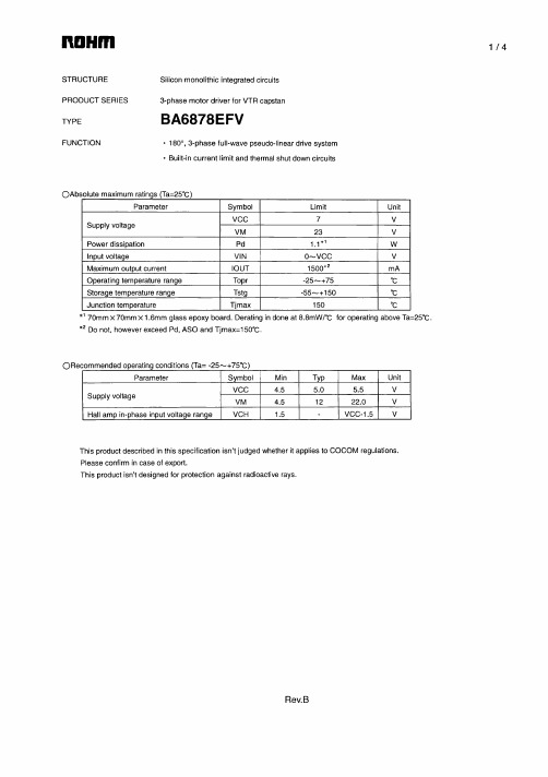
BA6878EFV中文资料
Please contact our sales offices for details ;
U.S.A / San Diego Atlanta Dallas Germany / Dusseldorf TEL : +1(858)625-3630 TEL : +1(770)754-5972 TEL : +1(972)312-8818 TEL : +49(2154)9210 FAX : +1(858)625-3670 FAX : +1(770)754-0691 FAX : +1(972)312-0330 FAX : +49(2154)921400 FAX : +44(1)908-282-528
(Contact address for overseas customers in Japan)
Yokohama
As of 18th. April 2005
Japan / (Internal Sales)
Tokyo Yokohama Nagoya Kyoto 2-1-1, Yaesu, Chuo-ku, Tokyo 104-0082 TEL : +81(3)5203-0321 FAX : +81(3)5203-0300 2-4-8, Shin Yokohama, Kohoku-ku, Yokohama, Kanagawa 222-8575 TEL : +81(45)476-2131 FAX : +81(45)476-2128 Dainagayo Building 9F 3-28-12, Meieki, Nakamura-ku, Nagoya,Aichi 450-0002 TEL : +81(52)581-8521 FAX : +81(52)561-2173 579-32 Higashi Shiokouji-cho, Karasuma Nishi-iru, Shiokoujidori, Shimogyo-ku, Kyoto 600-8216 TEL : +81(75)311-2121 FAX : +81(75)314-6559 TEL : +81(45)476-9270 FAX : +81(045)476-9271
CX8571原厂中文规格书

5.输出电容
第7页
宽输入电压范围 CC/CV 同步降压控制器
CX 8 57 1
十.功能描述
1. CC/CV控制模式 CX8571 具有具有CC/CV功能,即恒流输出控制模式和恒压输出控制模式。该功能可通过调整外部限
流电阻设置限流点。恒压输出控制模式下,输出电压精度可控制在±2%;恒流输出控制模式下,输出电流 精度可控制在±5%。
VOUT
(1
R FB1 R FB2
) VFB
R FB1
( VSEN 16.6K
1uA)
图 7. 12VIN 5VOUT 线缆补偿(RS=33mΩ) 第9页
宽输入电压范围 CC/CV 同步降压控制器
CX 8 57 1
3.电感选择
电感为输出负载维持连续的电流。电感电流纹波由电感量决定:
九、典型应用
CX 8 57 1
CX8571
CX8571
图3. CX8571 典型应用电路(VOUT=5V,IOUT=4.8A) RS1、RS2取值由客户所需要的限流电流Ilimt决定:RS1(或RS2)=VSEN/Ilimt,其中VSEN典型值为100mV。 注:如果只用一路输出限流,那么另外一个SEN脚要接GND。
数。在典型应用中,选择KRIPPLE=30%相当于峰峰值纹波电流为最大输出电流的30%。
有了电感量,电感峰值电流为IOUT×(1+KRIPPLE/2)。要确保电感的峰值电流低于转换器的限流点。最后,
选择合适磁芯尺寸以至于电感不会在达到电感峰值电流时饱和。
4.输入电容
输入电容用来维持转换器输入端电源上的纹波足够低,需要谨慎选择。推荐使用低ESR电容。在开关 期间,一旦有大电流流入或流出该电容时,它的ESR会影响效率。
NC7SZ08P5X,NC7SZ08M5X,NC7SZ08FHX, 规格书,Datasheet 资料
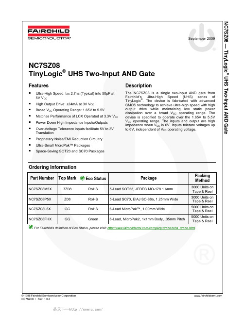
®TinyLogic UHS Two-Input AND GateFeaturesUltra-High Speed: t PD 2.7ns (Typical) into 50pF at 5V V CCHigh Output Drive: ±24mA at 3V V CCBroad V CC Operating Range: 1.65V to 5.5VMatches Performance of LCX Operated at 3.3V V CC Power Down High Impedance Inputs/OutputsOver-Voltage Tolerance inputs facilitate 5V to 3V TranslationProprietary Noise/EMI Reduction CircuitryUltra-Small MicroPak™ PackagesSpace-Saving SOT23 and SC70 Packages DescriptionThe NC7SZ08 is a single two-input AND gate from Fairchild’s Ultra-High Speed (UHS) series of TinyLogic®. The device is fabricated with advanced CMOS technology to achieve ultra-high speed with high output drive while maintaining low static power dissipation over a broad V CC operating range. The devise is specified to operate over the 1.65V to 5.5V V CC operating range. The inputs and output are high impedance when V CC is 0V. Inputs tolerate voltages up to 6V, independent of V CC operating voltage.Ordering InformationPart Number Top Mark Eco Status Package Packing MethodNC7SZ08M5X 7Z08 RoHS 5-Lead SOT23, JEDEC MO-178 1.6mm 3000 Units on Tape & ReelNC7SZ08P5X Z08 RoHS 5-Lead SC70, EIAJ SC-88a, 1.25mm Wide 3000 Units on Tape & ReelNC7SZ08L6X GG RoHS 6-Lead MicroPak™, 1.00mm Wide 5000 Units on Tape & ReelNC7SZ08FHX GG Green 6-Lead,MicroPak2, 1x1mm Body, .35mm Pitch 5000 Units on Tape & ReelFor Fairchild’s definition of Eco Status, please visit: /company/green/rohs_green.html.NC7SZ08 — TinyLogic ® UHS Two-Input AND GateFigure 1. Logic SymbolPin ConfigurationsFigure 2. SC70 and SOT23 (Top View)Figure 3. MicroPak (Top Through View)Pin DefinitionsPin # SC70 / SOT23Pin # MicroPakNameDescription1 1 A Input2 2 B Input3 3 GND Ground4 4 Y Output56 V CC Supply Voltage5 NC No ConnectFunction TableY=ABInputs OutputNC7SZ08 — TinyLogic ® UHS Two-Input AND GateSymbol Parameter Min. Max. UnitV CC Supply Voltage -0.5 6.0 V V IN DC Input Voltage -0.5 6.0 V V OUT DC Output Voltage -0.56.0 V V IN < -0.5V -50 I IK DC Input Diode Current V IN > 6.0V +20 mAV OUT < -0.5V-50I OK DC Output Diode Current V OUT > 6V, V CC =GND+20 mAI OUT DC Output Current±50 mA I CC or I GND DC V CC or Ground Current±50 mA T STG Storage Temperature Range -65 +150 °C T J Junction Temperature Under Bias+150 °C T LJunction Lead Temperature (Soldering, 10 Seconds)+260°CSOT-23 200SC70-5 150MicroPak-6 130 P DPower Dissipation at +85°CMicroPak2-6 120mWHuman Body Model, JESD22-A114 4000 ESD Charged Device Model, JESD22-C1012000VRecommended Operating ConditionsThe Recommended Operating Conditions table defines the conditions for actual device operation. Recommendedoperating conditions are specified to ensure optimal performance to the datasheet specifications. Fairchild does not recommend exceeding them or designing to Absolute Maximum Ratings.Symbol ParameterConditions Min. Max. UnitSupply Voltage Operating 1.65 5.50 V CCSupply Voltage Data Retention1.50 5.50 V V IN Input Voltage 0 5.5VV OUT Output Voltage0 V CC V T A Operating Temperature-40 +85 °C V CC at 1.8V, 2.5V ± 0.2V 0 20® UHS Two-Input AND Gate1.65 1.55 1.65 1.55 1.80 1.70 1.80 1.702.30 2.20 2.30 2.203.00 2.90 3.00 2.904.50V IN =V IH , I OH =-100µA 4.40 4.504.401.65 I OH =-4mA 1.29 1.52 1.292.30 I OH =-8mA 1.90 2.15 1.903.00 I OH =-16mA 2.50 2.80 2.40 3.00 I OH =-24mA 2.40 2.68 2.30VV OHHIGH LevelOutput Voltage4.50 I OH =-32mA 3.90 4.20 3.801.65 0.00 0.10 0.10 1.80 0.00 0.10 0.102.30 0.00 0.10 0.103.00 0.00 0.10 0.104.50V IN =V IL , I OL =100µA 0.00 0.10 0.10 1.65 I OL =4mA 0.80 0.24 0.24 2.30 I OL =8mA 0.10 0.30 0.30 3.00 I OL =16mA 0.15 0.40 0.40 3.00 I OL =24mA 0.22 0.55 0.55 VV OLLOW LevelOutput Voltage4.50 I OL =32mA0.22 0.55 0.55 I IN Input LeakageCurrent0 to 5.5V IN =5.5V, GND±1±10µAI OFF Power OffLeakage Current0 V IN or V OUT =5.5V 1 10 µAI CCQuiescent SupplyCurrent1.65 to 5.50 V IN =5.5V, GND220µA® UHS Two-Input AND Gate5.00 ± 0.500.5 2.2 4.1 0.5 4.4 3.30 ± 0.30 1.53.3 5.2 1.5 5.55.00 ± 0.50 C L =50pF,R L =500Ω0.8 2.7 4.5 0.84.8C IN Input Capacitance 0.00 4 pF 3.30 20 C PDPower DissipationCapacitance (2)5.0025pF Figure 6Note:2. C PD is defined as the value of the internal equivalent capacitance which is derived from dynamic operatingcurrent consumption (I CCD ) at no output lading and operating at 50% duty cycle. C PD is related to I CCD dynamic operating current by the expression: I CCD =(C PD )(V CC )(f IN )+(I CC static).Notes:3. C L includes load and stray capacitance.4. Input PRR=1.0MHz; t W 500ns.Figure 4. AC Test CircuitFigure 5. AC Waveforms=1.8ns; PRR=10MHz; Duty Cycle=50%.Test Circuit® UHS Two-Input AND Gate132LAND PATTERN RECOMMENDATIONC 0.10C0.20C A B0.60 REF0.550.35SEATING PLANE0.25GAGE PLANE8°0°NOTES: UNLESS OTHEWISE SPECIFIEDA) THIS PACKAGE CONFORMS TO JEDEC MO-178, ISSUE B, VARIATION AA,B) ALL DIMENSIONS ARE IN MILLIMETERS. 1.45 MAX1.300.900.150.051.900.950.500.301.502.600.701.00SEE DETAIL A0.220.08C) MA05Brev5TOP VIEW (0.30)Figure 7. 5-Lead SOT23, JEDEC MO-178 1.6mmPackage drawings are provided as a service to customers considering Fairchild components. Drawings may change in any manner without notice. Please note the revision and/or date on the drawing and contact a Fairchild Semiconductor representative to verify or obtain the most recent revision. Package specifications do not expand the terms of Fairchild’s worldwide terms and conditions, specifically the warranty therein, which covers Fairchild products.Always visit Fairchild Semiconductor’s online packaging area for the most recent package drawings: /packaging/.Tape and Reel Specifications®UHS Two-Input AND GateFigure 8. 5-Lead, SC70, EIAJ SC-88a, 1.25mm WidePackage drawings are provided as a service to customers considering Fairchild components. Drawings may change in any mannerwithout notice. Please note the revision and/or date on the drawing and contact a Fairchild Semiconductor representative to verifyor obtain the most recent revision. Package specifications do not expand the terms of Fairchild’s worldwide terms and conditions, specificallythe warranty therein, which covers Fairchild products.Always visit Fairchild Semiconductor’s online packaging area for the most recent package drawings:/packaging/.Tape and Reel Specifications® UHS Two-Input AND Gate2. DIMENSIONS ARE IN MILLIMETERS1. CONFORMS TO JEDEC STANDARD M0-252 VARIATION UAAD MAC06AREVCNotes:3. DRAWING CONFORMS TO ASME Y14.5M-1994TOP VIEWRECOMMENED LAND PATTERNBOTTOM VIEWA0.55MAX0.05C(0.75)(0.52)(0.30)6X 1X6X PIN 1DETAIL A0.075 X 45CHAMFER0.250.150.350.250.400.300.5(0.05) 1.0DETAIL APIN 1 TERMINAL0.400.300.450.350.100.000.10C B A 0.05CC0.05C0.050.005X 5X 6X(0.13)4X6XFigure 9. 6-Lead, MicroPak™, 1.0mm WidePackage drawings are provided as a service to customers considering Fairchild components. Drawings may change in any manner without notice. Please note the revision and/or date on the drawing and contact a Fairchild Semiconductor representative to verify or obtain the most recent revision. Package specifications do not expand the terms of Fairchild’s worldwide terms and conditions, specifically the warranty therein, which covers Fairchild products.Always visit Fairchild Semiconductor’s online packaging area for the most recent package drawings: /packaging/.®UHS Two-Input AND Gate DETAIL A5XFigure 10. 6-Lead, MicroPak2, 1x1mm Body, .35mm PitchPackage drawings are provided as a service to customers considering Fairchild components. Drawings may change in any mannerwithout notice. Please note the revision and/or date on the drawing and contact a Fairchild Semiconductor representative to verifyor obtain the most recent revision. Package specifications do not expand the terms of Fairchild’s worldwide terms and conditions, specificallythe warranty therein, which covers Fairchild products.Always visit Fairchild Semiconductor’s online packaging area for the most recent package drawings:/packaging/.NC7SZ08 — TinyLogic ® UHS Two-Input AND Gate。
NX8571SC741-BA中文资料
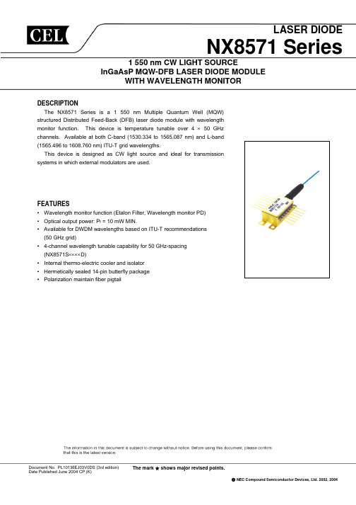
元器件交易网
NX8571 Series
8.2±0.2 5.4
0.3 1.0
PACKAGE DIMENSIONS (UNIT: mm)
8.89±0.13 10 MIN. 1.25
15.24 2.54
7
1
21.8±0.3 1.0 0.8
φ 0.9
8
14
0.5 20.83±0.25 26.04±0.25
monitor, E.O.L
∆ν Pf = 10 mW, CW, 3 dB down
SMSR Pf = 10 mW, CW
RIN Pf = 10 mW, 20 MHz to 3 GHz
Is
Pf = 10 mW, CW
ext Pf = 10 mW, CW
MIN. TYP. MAX. Unit
20
35
°C
1530.33 1530.72 1531.11 1531.50 1531.89 1532.29 1532.68 1533.07 1533.46 1533.85 1534.25 1534.64 1535.03 1535.42 1535.82 1536.21 1536.60 1537.00 1537.39 1537.79 1538.18 1538.58 1538.97 1539.37
Positive Slope (Even channel)
*2 Tracking Error: γ
Pf (mW)
TLD = Tset
10
TLD = Tset, TC = –5 to +70˚C
Pf
γ = 10 log Pf [dB]
10
0
Im
Im
ELECTRO-OPTICAL CHARACTERISTICS (Applicable to Thermistor and TEC: TLD = Tset, TC = −5 to +70°C)
上海中基国威电子股份有限公司M78用户手册V1.2说明书

M78用户手册V1.2上海中基国威电子股份有限公司SHANGHAI SINOMICON ELECTRONICS CO., LTD本公司保留对产品在可靠性、功能和设计方面的改进作进一步说明的权利目录1产品特性 (3)2引脚排列 (3)3引脚说明 (3)4功能框图 (4)5电气特性 (5)5.1极限参数 (5)5.2工作条件 (5)5.3DC特性 (5)5.4存储器特性 (6)5.5AC特性 (6)6按键扫描 (7)6.1描述 (7)6.2梯形键扫 (7)7发送编码 (9)7.1载波 (9)7.2逻辑0/1 (9)7.3帧格式 (9)图表目录图表1 SOP16封装顶视图 (3)图表2 M78管脚复用配置表 (3)图表3 M78功能框图 (4)图表4 梯形键扫配置图1(不使能LED) (7)图表5 梯形键扫配置图2(LED与S10复用) (8)图表6 梯形键扫配置图3(LED与S11复用) (8)1 产品特性● 工作电压 1.8~3.6V ● 工作温度 -10~70℃● 采用SOP16,SOP14,SOP8多种封装● 内建多次可擦写MTP 存储器,可多次更新配置(>1000次) ● 待机电流 <3uA ,支持低功耗待机键扫功能 ● 内建RC 振荡器8MHz ,常温±1%,全温±2% ● 载波频率可设(5KHz~60KHz ),占空比可设● 内建红外发射管驱动电路(驱动电流125/250/375/500mA 4档可选)● 内建LED 驱动电路(高低驱动可选,驱动电流1/2/4/8 mA 4档可选,LED 输出支持长亮、闪烁、载波亮3种模式可配置)● 最多支持12个键扫端口S0~S11● 采用梯型按键扫描方式,最大支持78键 ● 键扫周期4档可选(1/8/16/32 ms )● 逻辑电平宽度可设、帧数据位宽可设、帧时间可设 ● 重复码模式每个按键分别可设●支持4个用户码1设置值,每个按键分别可选2 引脚排列12345678910161514131211VSS NC LED/S10S9S8S7S6S5S4S3S2S1S0VDD IRD S11/LED图表 1 SOP16封装顶视图3 引脚说明符 号 描 述 类型 其 他 VSS 地 P — VDD 电源 P — LED LED 驱动端口 O — IRD 红外驱动端口 O — S0~S11按键扫描端口I/O—图表 2 M78管脚复用配置表4 功能框图Key ScanFrame EncodedRC OSC LED Driver IR Driver OSC DividerMTPVDDVSSS11S0S10… … LEDIRD图表 3 M78功能框图5电气特性5.1极限参数存储温度TSTG..............................................................................................-55℃~ 125℃供电极限电压VDD-VSS........................................................................................-0.3V ~ 4V输入极限电压VIN................................................................................VSS-0.3V ~ VDD+0.3VVDD最大承载电流IVDD.............................................................................................30mAVSS最大承载电流IVSS.............................................................................500mA(非持续)5.2工作条件符号描述最小值最大值单位VDD 工作电压 1.8 3.6 VT A工作温度-10 70 ℃5.3DC特性* 以下参数均为设计值典型值测试基本条件:TA=25℃,VDD=3V电流测试时输出无负载,输入不浮空存储温度TSTG.....-55℃ ~ 125℃符号描述最小值典型值最大值单位条件VDD 供电电压 1.8— 3.6 V —I DDA工作电流—0.5 1 mA —I DDS待机电流— 1 3 uA —V IL S0~S11输入低电压0 —0.4 VDD V SCHMITT输入特性V IH S0~S11输入高电压0.6 VDD —VDD V SCHMITT输入特性I LK S0~S11输入漏电流——±1 uA —R PU S0~S11上拉电阻20 40 80KΩ—50 100 200I LEDH LED高驱动电流— 2 —mA V OH = VDD-0.6V — 4 ——8 ——16 —I LEDL LED低驱动电流— 2 —mA V OL = VSS+0.6V — 4 ——8 ——16 —I IRD IRD驱动电流—125 —mA ——250 ——375 ——500 —5.4存储器特性存储操作最小值最大值单位条件MTP改写次数1,000 ———数据保持时间10 —year 85℃改写时间 1 600 us —5.5AC特性符号描述最小值典型值最大值单位备注F RC RC OSC振荡频率7.84 8 8.16 MHz VDD = 1.8~3.6V T = -10~70℃T KS键扫周期0.5 1 2ms —4 8 168 16 3216 32 646 按键扫描6.1 描述● 采用梯形键扫方式● 支持S0~S11共12个键扫端口,每个端口可单独配置 ● 低功耗键扫设计,支持空闲快速扫描● 支持按键去抖时间设置,最大去抖时间为4096个载波周期 ● 键扫周期4档可选(1/8/16/32 ms ) ● 支持多按键同时按下不发码● 重复码模式每个按键分别可设● 支持4个用户码1设置值,每个按键分别可选6.2 梯形键扫当不使能LED 输出功能时,梯形键扫最多支持78个按键,按键配置如图4所示。
PMC-687F光纤电流差动保护装置说明书_V1.0_20070830

PMC-687F光纤电流差动保护装置操作使用说明书(V1.0版)深圳市中电电力技术有限公司2007年8月30日目录1装置简介 (1)1.1概述 (1)1.2产品特点 (1)1.3基本功能 (1)1.4产品使用 (2)2技术指标 (2)2.1工作环境条件 (2)2.2额定参数 (2)2.3精度及误差 (2)2.4遥信分辨率 (3)2.5过载能力 (3)2.6继电器输出 (3)2.7开关量输入 (3)2.8电气绝缘性能 (3)2.9机械性能 (4)2.10光纤接口 (4)2.11电磁兼容性能 (4)3功能说明 (5)3.1电流差动保护 (5)3.1.1 启动条件 (5)3.1.2 闭锁条件: (5)3.1.3 分相差动的动作方程: (5)3.1.4 TA断线 (6)3.1.5 长期有差流 (6)3.1.6 通信可靠性 (6)3.1.7 数据同步 (6)3.2后备保护功能 (7)3.2.1复压过流保护(I段、II段) (7)3.2.2反时限过流保护 (8)3.2.3过负荷保护 (8)3.2.4相电流加速 (9)3.2.5零序过流保护(I、II段) (9)3.2.6远跳保护 (9)3.2.7绝缘监视 (10)3.2.8TV断线 (10)3.2.9重要遥信处理 (10)3.3测量监视功能 (10)3.3.1测量 (10)3.3.2遥信功能 (11)3.4控制功能 (11)3.5通讯功能 (11)3.6记录功能 (12)3.6.1事件记录 (12)3.6.2故障录波记录 (12)4操作使用说明 (13)4.1按键操作 (13)4.2信号指示灯 (13)4.3默认显示页面 (13)4.4显示结构 (14)4.5画面详细说明 (15)4.5.1数据查询 (15)4.5.2定值查询 (16)4.5.3事件记录 (18)4.5.4参数设置 (20)4.5.5装置维护 (22)4.5.6装置信息 (24)4.5.7定值清单 (24)5安装调试说明 (26)5.1安装 (26)5.1.1装置安装图 (26)5.1.2背板端子布置 (27)5.1.3端子排总体布置: (27)5.1.4交流及模拟量输入 (27)5.1.5工作电源 (27)5.1.6接地线的连接 (28)5.1.7通信接线 (28)5.2开出继电器的应用 (28)5.3开关量输入的应用 (28)5.4通电试验 (28)5.5模拟试验 (28)5.6装置故障分析 (29)6接线原理图 (31)7售后服务承诺 (32)7.1质量保证 (32)7.2装置升级 (32)7.3质保范围 (32)附录1:手册变更信息 (33)1装置简介1.1概述PMC-687F光纤电流差动保护装置是在消化吸收国内外先进技术的基础上设计开发的用于110kV及以下电压等级的带电流差动的线路保护装置。
CX108V 和 CX168 8路扬声器功率放大器说明书

Professional Power Amplifiers
CX168 | CX108V
Designed for permanently installed sound systems where rackspace is at a premium, QSC’s CX108V and CX168 provide unprecedented levels of channel density for multichannel amplifiers. The CX108V and CX168 provide 100 watts per channel at 70 volts and 90 watts per channel at 8 ohms respectively. With both models, each pair of channels may be bridged to configure these amplifiers as 4, 5, 6 or 7 channel units. Like the entire CX Series, the 8 channel models feature DataPorts for remote amplifier management or signal processing, incorporate QSC’s legendary PowerLight™ technology, and deliver our unmatched reputation for quality and reliability.
70V / 20 Hz – 20 kHz / 0.2% THD
Bridge-Mono Mode
16Ω / 20 Hz – 20 kHz / 0.1% THD
禧玛诺 Shimano 6870 DI2 经销商手册 用户

目录
重要提示..................................................................................................... 4 为了安全起见............................................................................................. 5
安装. .......................................................................................................... 14
将使用到的工具列表. .....................................................................................................................................................14 电线接线图 (总概念图) . ...............................................................................................................................................15 电线接线图 (连接器(A)侧) . .........................................................................................................................................17 安装双控手柄和刹车线. ................................................................................................................................................19 前拨链器的安装. ...............................................................................................................................................................22 后拨链器的安装. ...............................................................................................................................................................24 安装变速开关. ....................................................................................................................................................................25 安装连接器(A). ..................................................................................................................................................................32 安装连接器(B)...................................................................................................................................................................33 安装电池. ..............................................................................................................................................................................33
芯海 CS5817 用户手册说明书
CS5817用户手册Rev.1.0通讯地址:深圳市南山区南海大道1079号花园城数码大厦A栋9楼邮政编码:518067公司电话:+(86 755)86169257传真:+(86 755)86169057公司网站:R e v .1.0 第2页,共13页28引脚8段16位数码显示驱动介绍概述◆ 是一种8段×16位LED 显示驱动控制专用电路,内部集成MCU 数字接口、采用I^2C 协议、数据锁存器、内置时钟振荡电路和上电掉电复位电路。
特性说明◆ 采用CMOS 工艺 ◆ 工作电压:3.0V - 5.0V ◆ 超强的输入端口干扰能力 ◆ 显示模式:8段×16位 ◆ I 2C 串行总线(SCL ,SDA ) ◆ 内置RC 振荡 ◆ 内置上电复位电路 ◆ 封装形式:SOP28、SDIP28 ◆ ESD HDM :>6KV应用领域◆ VCD/DVD/DVB 显示 ◆ 电磁炉显示 ◆ 电饭煲显示 ◆ 空调显示◆ 机顶盒显示◆小家电LED 数码显示驱动历史修改记录时间记录版本号2012-12-24 换新LOGO初稿完成 1.0目录CS5817用户手册 (1)历史修改记录 (3)目录 (4)1产品概述 (5)1.1管脚配置 (5)1.2内部功能框图 (6)1.3管脚定义说明 (6)2电气参数 (7)3功能描述 (9)4指令说明 (10)5应用电路 (11)6封装形式 (12)1产品概述1.1管脚配置图 1-1 引脚配置图1.2内部功能框图1.3管脚定义说明符号管脚名称管脚号说明SCL 时钟输入9 I2C 总线串行接口的时钟输入SDA 数据输入10 I2C 总线串行接口的数据输入SEG0—SEG7 输出(段)23-24,26-28,1-3 段输出VDD 逻辑电源25 5V±10%GRID0—输出(位)4-8,12-22 位输出GRID15GND 逻辑地11 系统地注:SEG引脚连接LED阳极,GRID引脚连接LED阴极。
NX8中央控制器的说明书

al a rm e.c omm et àl ad i sp os i ti o ndup ubl ic , v i aw ww .d oc a l ar m e.c om ,d el ad oc um en t at i on te c h ni q ue do nt l e s réf ére n c e s ,m a r q u e s e tl o g o s , s o n t l a p ro p r i ét é d e s n t e u r s r e s p e c t i f sLa centrale NX8 peut gérer des émetteurs radio grâce aux modules NX408EI, NX416EI, NX448EI.Les émetteurs compatibles sont : NX450I, NX451I,NX470I, NX475I, NX480I et NX490I.Le récepteur radio peut s’installer dans le coffret de la centrale. Le raccordement à la carte mère se fait par un bus 3 fils comprenant l’alimentation et les données.L’installation de la carte réceptrice radio nécessite quelques précautions d’installation :Laisser au moins 30 cm au-dessus de la centrale afin de placer les antennes de la carte de réception radioEviter de placer la carte de réception radio dans un endroit humideEviter les armoires métalliques, armoires électriques, les chaufferies etc...Installation Carte réceptionCe chapitre indique l’installation de la carte, la fixation sur le coffret et l’installation des antennes.ATTENTION : Vérifier que vous n’êtes pas chargéélectriquement. Pour cela, toucher le boîtier métallique ou portez un bracelet anti statique pour éviter toute décharge électro statique1/ Après avoir installé le coffret de la NX8, fixer les vis prévues à cet effet avec l’écrou et les rondelles fournies. L’emplacement des vis doit être conforme àla figure 1.Figure 1 : Installation des vis de fixation2/ Installer le guide sans le fixer complètement grâce àla vis auto taraudeuse fournie. L’emplacement de ce guide doit se situer sous les vis fixées au point 1. Voir Figure 2Figure 2 : Préinstallation du guide de maintien de lacarte de réception radio.al a rm e.c omm et àl ad i sp os i ti o nd up ub l ic , v i aw ww .d oc a l ar m e.c om ,d el ae s p e c t if sNX408I - NX416I - NX448IFigure 3 : Installation de la carte dans le coffret4/ Dès que la carte est installée, vissez la vis auto taraudeuse pour fixer solidement la carte5/ Placer les antennes dans les emplacements prévus àcet effet (Voir Figure 4)Figure 4 : InseFirsions des antennes Figure 4 : insertion des antenness r e s p e c t i f sr e s p e c t i f sNX408I - NX416I - NX448Iu r s r e s p e c t i f sNX408I - NX416I - NX448Iw ww .u r s r e s p e c t i f sNX408I - NX416I - NX448ICAD_NX408EI_416EI_448EI_NI.docVersion 1.0Page 11/11。
NX8567SAM573-CC中文资料

PART NUMBER
SYMBOLS R B IC VC
PARAMETERS AND CONDITIONS Thermistor Resistance, TLD = 25°C B Constant Cooler Current, TLD = Tset Cooler Voltage, TLD = Tset
Im (λ) Im @100%
ηλ =
I1 – I2 λ1 – λ2
[ µA/pm]
Im (λ)
Im @100%
I1: Im @75% Im (λp)
I2: Im @25%
Operation region Locking point
I2: Im @75% Im (λp)
I1: Im @25%
Operation region Locking point
ELECTRO-OPTICAL CHARACTERISTICS (TLD = Tset, TC = -5 to +70°C, unless otherwise speciÞed)
PART NUMBER
NX8567SA SERIES
SYMBOLS TSET IOP Vcenter Vmod VFLD ITH
Vcenter
: a certain point between -2.0 and -0.5 V
Vmod
: a certain point 3 V or below
Iop
: a certain point between 50 and 80 mA
3. Available for DWDM wavelenght based on ITU-T recommendation (100 GHz grid). Please refer to ORDERING INFORMATION.
Siemens SCALANCE X108数据表 6GK5108-0BA00-2AA3说明书

6GK5108-0BA00-2AA3
SCALANCE X108, Unmanaged IE switch, 8x 10/100 Mbit/s RJ45 ports, LED diagnostics, error-signaling contact with set button, redundant Power supply Manual available as a download
-20 ... +70 °C -40 ... +80 °C -40 ... +80 °C
95 %
IP30 compact 60 mm 125 mm 124 mm 0.78 kg
Yes Yes Yes No
Product functions / management, configuration, engineering Product function
DC
24 V 18 V 32 V Yes 0.6 A / 60 V 0.14 A
3.36 W
Ambient conditions Ambient temperature ● during operation ● during storage ● during transport Relative humidity ● at 25 °C / without condensation / during operation / maximum Protection class IP Design Width Height Depth Net weight Mounting type ● 35 mm DIN rail mounting ● wall mounting ● S7-300 rail mounting ● S7-1500 rail mounting
681KD10JX中文资料

182KD10JX*thru180LD10JX*11 to 1000 VoltsVaristor2.6 to 247JouleFeatures• High Surge, High Energy• Designed to be Operated Continuously Across AC Power Lines • No Derating Up to 85к Ambient• Available in Tape and Reel or Bulk PackMaximum Ratings• Operating Ambient Temperature Range: -55к to +85к• Storage Temperature Range: -55к to +125к• Temperature Coefficient (өV) of Clamping Voltage (V C ) at Specified Test Current:<0.05%/к•Varistor voltage temperature coefficient:CURRENT, ENERGY AND POWER DERATING CURVE-551606080100120204060AMBIENT TEMPERATURE (°C)PERCENT OF RATED VALUE14080100120•UL Recognized File # E306895(UL1449) and E306942(UL1414)omp onents 20736 Marilla Street Chatsworth! "# $ % ! "#TMMicro Commercial ComponentsNote : 'X' can be S, C, I or Y .*'S' denotes straight lead'C' denotes out crimped lead 'I' denotes inner crimped lead 'Y' denotes kink lead160x(100/ć)182KD10JX thru 180LD10JX*680K-180L Max. Clamping Voltage testing current 5A .(V)(V)(J)(V)(V)182KD10JX 10001465247.01800(1620-1980)2970112KD10JX 680895155.01100(990-1210)1815102KD10JX 625825140.01000(900-1100)1650911KD10JX 550745127.0910(819-1001)1500821KD10JX 510670118.0820(738-902)1355781KD10JX 485640116.0780(702-858)1290751KD10JX 460615115.0750(675-825)1240681KD10JX 420560112.0680(612-748)1120621KD10JX 385505107.0620(558-682)1025561KD10JX 350460102.0560(504-616)920511KD10JX 32041892.0510(459-561)845471KD10JX 30038585.0470(423-517)775431KD10JX 27535080.0430(387-473)710391KD10JX 25032070.0390(351-429)650361KD10JX 23030065.0360(324-396)595331KD10JX 21027558.0330(297-363)550301KD10JX 19525052.0300(270-330)505271KD10JX 17522549.0270(243-297)455241KD10JX 15020042.0240(216-264)395221KD10JX 14018039.0220(198-242)360201KD10JX 13017035.0200(180-220)330181KD10JX 11515032.0180(162-198)300151KD10JX 9512525.0150(135-165)250121KD10JX 7510022.0120(108-132)200101KD10JX 608518.0100(90-110)165820KD10JX 506514.082(74-90)135680KD10JX 40569.868(61-75)*135560KD10JX 35458.156(50-62)*110470KD10JX 3038 6.847(42-52)*93390KD10JX 2531 5.639(35-43)*77330KD10JX 2026 4.833(30-36)*65270KD10JX 1722 3.927(24-30)*53220KD10JX 1418 3.222(20-24)*43180LD10J X11142.618(15-21)*36V25A (A)10005000.05350025000.4Rated WattageVaristor VoltageMaximum Clamping Voltage ACrms DC 10/1000us1 time2 times(W)V1mA Part NumberMaximum AllowableVoltageMaximum EnergyWithstanding Surge Current 8/20usElectrical Characteristics @ 25O C Unless Otherwise NotedMicro Commercial Components570504030AV-I Curve (820K to 561K)V100908060200907069580605020400300200150100AV-I Curve (180L to 680K)VTMMicro Commercial Components2000400030005000AV-I Curve (621K to 182K)V1100101000100V-I Surge Life Time Ratings (180L to 680K)AµsImpulse Current – AmperesImpulse Width – Micro seconds101001001000V-I Surge Life Time Ratings (820K to182K)AµsImpulse Current – Amperes Impulse Width – Micro secondsMicro Commercial ComponentsNote 2.T Thickness (max.)Unit:mmMicro Commercial ComponentsPart CodeD05D07D10D14D20182K 12.612.813.5112K 10.510.711.2102K 9.910.110.7911K 9.49.610.1821K 8.38.89.09.5781K 8.18.68.89.3751K 7.97.98.48.69.1681K 7.57.58.08.28.7621K 7.27.27.67.88.3561K 6.9 6.97.37.58.0511K 6.6 6.67.07.27.7471K 6.4 6.4 6.87.07.5431K 6.1 6.1 6.5 6.77.2391K 5.3 5.3 5.7 5.9 6.4361K 5.1 5.1 5.5 5.7 6.2331K 4.9 4.9 5.3 5.5 6.0301K 4.8 4.8 5.2 5.4 5.9271K 4.6 4.6 5.0 5.2 5.7241K 4.4 4.4 4.8 5.0 5.5221K 4.3 4.3 4.7 4.9 5.4201K 4.2 4.2 4.6 4.8 5.3181K 4.1 4.1 4.5 4.7 5.2151K 4.5 4.5 4.9 5.1 5.6121K 4.1 4.1 4.5 4.6 5.3101K 3.9 3.9 4.4 4.5 5.1820K 3.8 3.8 4.3 4.4 4.9680K 5.5 5.5 6.0 6.1 6.1560K 5.0 5.0 5.5 5.6 5.6470K 5.0 5.0 5.5 5.6 5.6390K 4.7 4.7 5.1 5.2 5.4330K 4.7 4.7 5.1 5.2 5.4270K 4.7 4.7 5.1 5.2 5.4220K 4.5 4.5 4.9 5.0 5.3180L4.54.54.95.05.2Micro Commercial Components***IMPORTANT NOTICE***Micro Commercial Components Corp.reserve s the right to make changes without further notice to any product herein to make corrections, modifications , enhancements , improvements , or other changes .Micro Commercial Components Corp.does not assume any liability arising out of the application or use of any product described herein; neither does it convey any license under its patent rights ,northe rights of others . The user of products in such applications shall assume all risks of such use and will agree to hold Micro Commercial Components Corp.and all the companies whoseproducts are represented on our website, harmless against all damages.***APPLICATIONS DISCLAIMER***Products offer by Micro Commercial Components Corp.are not intended for use in Medical,Aerospace or Military Applications.。
南海八号逆变器使用说明书

南海八号逆变器使用说明书
逆变器的作用以及原理是一种能够将DC12V直流电转换为和市电相同的AC220V交流电,供一般电器使用,是一种方便的车用电源转换器。
车用逆变器是专为小型用电器生产的逆变器,它是目前最先进的直流交流转换产品之一。
逆变器的使用说明书如下。
1、将转换器放置在平坦的地方,确保开关是关的。
2、将红、黑线分别与转换器的红黑接线柱相连,带夹子的一端分别夹在电瓶的正、负极上(红线夹电瓶正极,黑线夹负极)。
如果使用点烟器插头,则将插头插入点烟器插孔即可。
3、将电器的电源插头插入AC插口。
4、打开转换器开关,即可使用。
BA6872资料

BA6872AFM
826
元器件交易网 Motor driver ICs
FCircuit operation Capstan three-phase motor driver (1) Pseudo-linear output The IC generates a trapezoidal (pseudo-linear) output current whose waveform phase is 30 degrees ahead of that of the Hall input voltage.
(2) Torque control The output current can be controlled by adjusting the voltage applied to the torque control pins. The pins are the inputs to a differential amplifier, and the reference voltage side is biased with a voltage of 2.2V (Typ.).
BA6872AFM
(4) Motor direction control (ED / S pin) The motor mode is forward when the ED / S is voltage is less than 2.2V, and reverse when the ED / S is voltage is greater than 2.8V. (5) Output transistor saturation prevention circuit This circuit monitors the output voltage and maintains the operation of the output transistors below their saturation levels. Operating the transistors in the linear characteristic range provides good control over a wide current range, and good torque characteristics even during overload.
Schwinn IC4 IC8 安装手册 用户手册说明书
™IC4 / IC8锻炼时使用其它健身应用程序本健身器材整合 Bluetooth®连接功能,允许配合各种数码伴侣使用。
如需受支持伴侣的最新列表,请访问:/partners安装手册/用户手册2重要安全说明 3 安全警报标签/序列号 5规格 6安装前 6部件 7配件 8工具 8安装 9 安装鞋夹(夹紧器) 13移动和存放器材 14 水平安置器材 14功能 15 紧急停止16 控制台功能16远程心率监测 17 鞋夹(夹紧器) 18操作 19 调整 19 锁定后存放 22 通电 22 更改计量单位(英制/公制) 22 暂停或停止 22维护 23 检查传动皮带张力 23 维护部件 24检修25Nautilus, Inc., 5415 Centerpoint Parkway, Groveport, OH 43125 USA, - 客户服务部:北美(800)605-3369,******************| Nautilus (Shanghai) Fitness Equipments Co, Ltd,中国上海市长宁区长宁路 1018号 1701、1702 室 200042, - 86 21 6115 9668 | 美国以外 | 在中国印刷 | © 2019 Nautilus, Inc. | Schwinn 、Schwinn Quality 标志、Nautilus 和 Bowflex 是 Nautilus, Inc. 拥有或获许可的商标,这些商标已注册或受美国和其他国家的习惯法的保护。
Bluetooth ® 字标和标志是 Bluetooth SIG, Inc. 拥有的注册商标,Nautilus, Inc. 已获得授权使用任何此类标志。
原版手册 - 仅限英文版本为获得保修服务,请妥善保存原始购买证明并填写以下信息:序列号 __________________________购买日期 ____________________如在美国/加拿大购买:若要注册产品质保,请访问:/register 或致电 1 (800) 605–3369。
- 1、下载文档前请自行甄别文档内容的完整性,平台不提供额外的编辑、内容补充、找答案等附加服务。
- 2、"仅部分预览"的文档,不可在线预览部分如存在完整性等问题,可反馈申请退款(可完整预览的文档不适用该条件!)。
- 3、如文档侵犯您的权益,请联系客服反馈,我们会尽快为您处理(人工客服工作时间:9:00-18:30)。
LASER DIODENX8571 Series1 550 nm CW LIGHT SOURCEInGaAsP MQW-DFB LASER DIODE MODULEWITH WAVELENGTH MONITORDESCRIPTIONThe NX8571 Series is a 1 550 nm Multiple Quantum Well (MQW) structured Distributed Feed-Back (DFB) laser diode module with wavelength monitor function. This device is temperature tunable over 4 × 50 GHz channels. Available at both C-band (1530.334 to 1565.087 nm) and L-band (1565.496 to 1608.760 nm) ITU-T grid wavelengths.This device is designed as CW light source and ideal for transmission systems in which external modulators are used.FEATURES• Wavelength monitor function (Etalon Filter, Wavelength monitor PD) • Optical output power: P f = 10 mW MIN.• Available for DWDM wavelengths based on ITU-T recommendations (50 GHz grid)• 4-channel wavelength tunable capability for 50 GHz-spacing (NX8571S ××××D)• Internal thermo-electric cooler and isolator • Hermetically sealed 14-pin butterfly package • Polarization maintain fiber pigtailDocument No. PL10136EJ03V0DS (3rd edition) Date Published June 2004 CP (K)© NEC Compound Semiconductor Devices, Ltd. 2002, 2004The mark shows major revised points.PACKAGE DIMENSIONS (UNIT: mm)OPTICAL FIBER CHARACTERISTICSParameter Specification UnitOuter Diameter0.9±0.1 mm Minimum Fiber Bending Radius 25 mm Fiber Length1 000 MIN.mmData Sheet PL10136EJ03V0DS2ABSOLUTE MAXIMUM RATINGSRatings UnitParameter SymbolForward Current of LD I F 300 mAReverse Voltage of LD V R 2.0 VForward Current of PD I F 10 mAReverse Voltage of PD V R 20 VOperating Case Temperature T C−20 to +70 °CStorage Temperature T stg−40 to +85 °CLead Soldering Temperature T sld260 (10 sec.) °CELECTRO-OPTICAL CHARACTERISTICS (T LD = T set, T C = −5 to +70°C, unless otherwise specified)MAX.UnitTYP.Parameter Symbol Conditions MIN.channel 20 35 °CLaser Set Temperature T set Single4 channel tunable 10 45Forward Voltage V F P f = 10 mW 0.9 1.2 2.5 VThreshold Current I th20 40 mAOperation Current I op P f = 10 mW 70 125 mAOptical Output Power from Fiber P f I F = 125 mA, T LD = T set 10 mWITU-T *1 1 609 nm530Peak Emission Wavelength λp P f = 10 mW, CW, T LD = T set 1−20 +20 pm Wevelength Stability −T LD = T set, applicable to wavelengthmonitor, E.O.LSpectral Line Width ∆νP f = 10 mW, CW, 3 dB down 1 2 MHzSide Mode Suppression Ratio SMSR P f = 10 mW, CW 35 45 dBRelative Intensity Noise RIN P f = 10 mW, 20 MHz to 3 GHz −150 dB/HzOptical Isolation I s P f = 10 mW, CW 30 dBPolarization Extinction Ratio *2ext P f = 10 mW, CW 20 dB*1Available for DWDM wavelengths based on ITU-T recommendations (50 GHz grid).Please refer to Table A.*2 Polarization state of LD is aligned parallel to the slow axis.Data Sheet PL10136EJ03V0DS 3ELECTRO-OPTICAL CHARACTERISTICS (Applicable to Monitor PD: T LD = T set , T C = −5 to +70°C)Parameter Symbol Conditions MIN. TYP. MAX. UnitMonitor Current (P f Monitor) I m (P f ) P f = 10 mW, V R = 5 V20 200 µA Monitor Current (λp Monitor) I m (λp ) P f = 10 mW, V R = 5 V, Locking point 10100µAOperation Region *1I m (λ)25 75%⏐λ1−λ2⏐ 90pm Discrimination Slope *1ηλ0.05µA/pm Dark Current I D V R = 5 V 2 10 nA Tracking Errorγ*2I m = const.0.5dB*1 Operation region, Discrimination slope, Slope assignmentI I m I m (λp I m I 1: I m I 2: I m Negative Slope (Odd channel)I m (λ)I m I m (λp I m I 2: I m I 1: I m λPositive Slope (Even channel)µ*2 Tracking Error: γmmset, T C = –5 to +70˚C10P fγ = 10 log[dB]P f 10ELECTRO-OPTICAL CHARACTERISTICS(Applicable to Thermistor and TEC: T LD = T set , T C = −5 to +70°C)Parameter Symbol Conditions MIN. TYP. MAX. UnitThermistor Resistance R T LD = 25°C 9.5 10.0 10.5 k Ω B Constant B T LD = 25°C3 350 3 450 3 550 K Cooler Current I C ∆T = 70 − T set , P f = 10 mW 1.5 A Cooler VoltageV C∆T = 70 − T set , P f = 10 mW3.0VData Sheet PL10136EJ03V0DS4ORDERING INFORMATIONNX8571SC -BAWith FC-PC connector Without : Single channel D : 4 channel tunable Wavelength code : Refer to Table A Package codeTable A: DWDM wavelength base on ITU-T recommendations (@ T LD = T set ) (1/7)Wavelength CodeITU-T Wavelength*1Frequency Monitor Slope 4 channel tunablesingle channel (nm)(THz)315D 303 1530.33 195.90 Negative 307 1530.72 195.85 Positive 311 1531.11 195.80 Negative 315 1531.50 195.75 Positive 330D 318 1531.89 195.70 Negative 322 1532.29 195.65 Positive 326 1532.68 195.60 Negative 330 1533.07 195.55 Positive 346D 334 1533.46 195.50 Negative 338 1533.85 195.45 Positive 342 1534.25 195.40 Negative 346 1534.64 195.35 Positive 362D 350 1535.03 195.30 Negative 354 1535.42 195.25 Positive 358 1535.82 195.20 Negative 362 1536.21 195.15 Positive 377D 366 1536.60 195.10 Negative 370 1537.00 195.05 Positive 373 1537.39 195.00 Negative 377 1537.79 194.95 Positive 393D 381 1538.18 194.90 Negative 385 1538.58 194.85 Positive 389 1538.97 194.80 Negative 393 1539.37 194.75 Positive*1 The value which omitted and computed the 3rd place below the decimal pointData Sheet PL10136EJ03V0DS5Table A: DWDM wavelength base on ITU-T recommendations (@ T LD = T set) (2/7)Slope Wavelength Code ITU-T Wavelength *1Frequency Monitor4 channel tunable single channel (nm) (THz)Negative194.70 409D 397 1539.76Positive194.65 4011540.16Negative194.601540.55405Positive194.551540.95409Negative194.50 425D 413 1541.34Positive194.451541.74417194.40Negative1542.14421Positive194.351542.53425Negative 441D 429 1542.93194.30Positive194.251543.33433194.20Negative1543.73437Positive194.151544.12441194.10Negative 457D 445 1544.52194.05Positive1544.92449194.00Negative1545.32453Positive193.951545.72457Negative193.90 473D 461 1546.11Positive193.851546.51465Negative193.801546.91469193.75Positive1547.31473Negative 489D 477 1547.71193.70193.65Positive1548.11481193.60Negative1548.51485193.55Positive1548.91489Negative 505D 493 1549.31193.50Positive193.45 4971549.71Negative193.401550.11501Positive193.351550.51505193.30Negative 521D 509 1550.91Positive193.251551.31513Negative193.201551.72517Positive193.15 5211552.12*1The value which omitted and computed the 3rd place below the decimal point6Data Sheet PL10136EJ03V0DSTable A: DWDM wavelength base on ITU-T recommendations (@ T LD = T set) (3/7)Slope Wavelength Code ITU-T Wavelength *1Frequency Monitor4 channel tunable single channel (nm) (THz)Negative193.10 537D 525 1552.52Positive193.05 5291552.92Negative193.001553.32533Positive192.951553.73537Negative192.90 553D 541 1554.13Positive192.851554.53545192.80Negative1554.94549Positive192.751555.34553Negative 569D 557 1555.74192.70Positive192.651556.15561192.60Negative1556.55565Positive192.551556.95569192.50Negative 585D 573 1557.36192.45Positive1557.76577192.40Negative1558.17581Positive192.351558.57585Negative 602D 589 1558.98192.30Positive192.25 5931559.38Negative192.201559.79597Positive192.151560.20602Negative192.10 618D 606 1560.60Positive192.05 6101561.01Negative192.001561.41614191.95Positive1561.82618Negative191.90 634D 622 1562.23Positive191.851562.64626Negative191.801563.04630191.75Positive1563.45634Negative191.70 650D 638 1563.86Positive191.65 6421564.27Negative191.60 6461564.67Positive191.551565.08650*1The value which omitted and computed the 3rd place below the decimal pointData Sheet PL10136EJ03V0DS 7Table A: DWDM wavelength base on ITU-T recommendations (@ T LD = T set) (4/7)Slope Wavelength Code ITU-T Wavelength *1Frequency Monitor4 channel tunable single channel (nm) (THz)Negative191.50 667D 654 1565.49Positive191.45 6591565.90Negative191.401566.31663Positive191.351566.72667Negative191.30 683D 671 1567.13Positive191.251567.54675191.20Negative1567.95679Positive191.151568.36683Negative 700D 687 1568.77191.10Positive191.051569.18691191.00Negative1569.59695Positive190.951570.00700190.90Negative 716D 704 1570.41190.85Positive1570.82708190.80Negative1571.23712Positive190.751571.65716Negative190.70 733D 720 1572.06Positive190.651572.47724Negative190.601572.88728190.55Positive1573.30733Negative 749D 737 1573.71190.50190.45Positive1574.12741190.40Negative1574.54745190.35Positive1574.95749Negative 766D 753 1575.36190.30Positive190.25 7571575.78Negative190.201576.19761Positive190.151576.61766190.10Negative 782D 770 1577.02Positive190.051577.44774Negative190.001577.85778Positive189.95 7821578.27*1The value which omitted and computed the 3rd place below the decimal point8Data Sheet PL10136EJ03V0DSTable A: DWDM wavelength base on ITU-T recommendations (@ T LD = T set) (5/7)Slope Wavelength Code ITU-T Wavelength *1Frequency Monitor4 channel tunable single channel (nm) (THz)Negative189.90 799D 786 1578.68Positive189.85 7911579.10Negative189.801579.51795Positive189.751579.93799Negative189.70 816D 803 1580.35Positive189.651580.76807189.60Negative1581.18811Positive189.551581.60816Negative 832D 820 1582.01189.50Positive189.451582.43824189.40Negative1582.85828Positive189.351583.27832189.30Negative 849D 836 1583.69189.25Positive1584.10841189.20Negative1584.52845Positive189.151584.94849Negative 866D 853 1585.36189.10Positive189.05 8571585.78Negative189.001586.20862Positive188.951586.62866Negative188.90 883D 870 1587.04Positive188.85 8741587.46Negative188.801587.88878188.75Positive1588.30883Negative188.70 899D 887 1588.72Positive188.651589.14891Negative188.601589.56895188.55Positive1589.98899Negative188.50 916D 904 1590.41Positive188.45 9081590.83Negative188.40 9121591.25Positive188.351591.67916*1The value which omitted and computed the 3rd place below the decimal pointData Sheet PL10136EJ03V0DS 9Table A: DWDM wavelength base on ITU-T recommendations (@ T LD = T set) (6/7)Slope Wavelength Code ITU-T Wavelength *1Frequency Monitor4 channel tunable single channel (nm) (THz)933D 921 1592.10Negative188.30Positive188.25 9251592.52Negative188.201592.94929Positive188.15 9331593.36Negative188.10 950D 937 1593.79Positive188.051594.21942188.00Negative1594.64946Positive187.95 9501595.06Negative187.90 967D 954 1595.48Positive187.851595.91959187.80Negative1596.33963Positive187.751596.76967Negative 984D 971 1597.18187.70Positive187.651597.61976187.60Negative1598.04980Positive187.55 9841598.46Negative 6001D 988 1598.89 187.50Positive187.45 9931599.32Negative187.401599.74997187.35Positive1600.176001Negative 6018D 6006 1600.60 187.30Positive187.25 60101601.02Negative187.20 60141601.45Positive187.151601.886018Negative 6035D 6023 1602.31 187.106027Positive187.051602.74187.00Negative1603.166031Positive186.951603.596035Negative 6053D 6040 1604.02 186.90Positive186.85 60441604.45Negative186.80 60481604.88Positive186.75 60531605.31*1The value which omitted and computed the 3rd place below the decimal point10Data Sheet PL10136EJ03V0DSTable A: DWDM wavelength base on ITU-T recommendations (@ T LD = T set) (7/7)Slope Wavelength Code ITU-T Wavelength *1Frequency Monitor4 channel tunable single channel (nm) (THz)6070D 6057 1605.74 186.70NegativePositive186.65 60611606.17Negative186.601606.606066Positive186.551607.036070Negative 6087D 6074 1607.46 186.50Positive186.45 60781607.89Negative186.40 60831608.32Positive186.351608.766087*1The value which omitted and computed the 3rd place below the decimal pointData Sheet PL10136EJ03V0DS 11TYPICAL CHARACTERISTICS (T LD = 25°C, unless otherwise specified)Forward Current I F (mA)T C = 70˚CT h e r m i s t o r R e s i s t a n c e R (k Ω)C o o l e r E l e c t r i c P o w e r C o n s u m p t i o n (W )151020253035SPECTRUMR e l a t i v e I n t e n s i t y (d B )Wavelength λ (nm)OPTICAL OUTPUT POWER FROM FIBER, MONITOR CURRENT (P f MONITOR) vs. FORWARD CURRENTO p t i c a l O u t p u t P o w e r f r o m F i b e r P f (m W )THERMISTOR RESISTANCE vs.AMBIENT TEMPERATUREAmbient Temperature T A (˚C)Laser Set Temperature T set (˚C)–10–30–50–700–20–40–601 529.11 539.11 549.11 534.11 544.1–8030.025.020.015.010.05.04.03.53.02.52.01.51.00.50.00501001502000.300.250.200.150.100.050P fI m (P f )M o n i t o r C u r r e n t (P f M o n i t o r ) I m (P f ) (m A )COOLER ELECTRIC POWER CONSUMPTION vs. LASER SET TEMPERATURERemark The graphs indicate nominal characteristics.Data Sheet PL10136EJ03V0DS12REFERENCEDocument Name Document No. OPTICAL SEMICONDUCTOR DEVICES FOR FIBEROPTIC COMMUNICATIONS SELECTION GUIDE PL10161EOpto-Electronics Devices Pamphlet PX10160EData Sheet PL10136EJ03V0DS 134590 Patrick Henry DriveSanta Clara, CA 95054-1817Telephone: (408) 919-2500Facsimile: (408) 988-0279Subject: Compliance with EU DirectivesCEL certifies, to its knowledge, that semiconductor and laser products detailed below are compliant with the requirements of European Union (EU) Directive 2002/95/EC Restriction on Use of Hazardous Substances in electrical and electronic equipment (RoHS) and the requirements of EU Directive 2003/11/EC Restriction on Penta and Octa BDE.CEL Pb-free products have the same base part number with a suffix added. The suffix –A indicates that the device is Pb-free. The –AZ suffix is used to designate devices containing Pb which are exempted from the requirement of RoHS directive (*). In all cases the devices have Pb-free terminals. All devices with these suffixes meet the requirements of the RoHS directive.This status is based on CEL’s understanding of the EU Directives and knowledge of the materials that go into its products as of the date of disclosure of this information.Restricted Substanceper RoHS Concentration Limit per RoHS(values are not yet fixed)Concentration containedin CEL devices-A -AZLead (Pb) < 1000 PPMNot Detected (*) Mercury < 1000 PPM Not DetectedCadmium < 100 PPM Not DetectedHexavalent Chromium < 1000 PPM Not DetectedPBB < 1000 PPM Not DetectedPBDE < 1000 PPM Not DetectedIf you should have any additional questions regarding our devices and compliance to environmentalstandards, please do not hesitate to contact your local representative.Important Information and Disclaimer: Information provided by CEL on its website or in other communications concerting the substancecontent of its products represents knowledge and belief as of the date that it is provided. CEL bases its knowledge and belief on information provided by third parties and makes no representation or warranty as to the accuracy of such information. Efforts are underway to betterintegrate information from third parties. CEL has taken and continues to take reasonable steps to provide representative and accurateinformation but may not have conducted destructive testing or chemical analysis on incoming materials and chemicals. CEL and CELsuppliers consider certain information to be proprietary, and thus CAS numbers and other limited information may not be available forrelease.In no event shall CEL’s liability arising out of such information exceed the total purchase price of the CEL part(s) at issue sold by CEL tocustomer on an annual basis.See CEL Terms and Conditions for additional clarification of warranties and liability.元器件交易网。
