STL整理v3
STL容器整理(office2003版)
第一类容器(支持迭代器)序列容器Vector(随机迭代访问)说明:vector是一种动态数组,是基本数组的类模板。
其内部定义了很多基本操作。
#include <vector> 注意:头文件没有“.h”构造:vector<int> v1; // 默认构造函数vector<int> v2(init_size,0); //如果预先定义了:int init_size;他的成员值都被初始化为0;vector<int> v3(v2); // 复制构造函数,构造一个新的向量,作为已存在的向量的完全复制;vector<int> v4(first, last) // 带两个常量参数的构造函数,产生初始值为一个区间的向量。
区间由一个半开区间[first, last) 来指定。
方法:assign(beg,end) 将(beg; end)区间中的数据赋值给对象。
assign(n,elem)将n个elem的拷贝赋值给对象。
at(idx)传回索引idx所指的数据,如果idx越界,抛出out_of_range。
back()传回最后一个数据,不检查这个数据是否存在。
begin()传回迭代器中的第一个数据地址。
capacity()返回容器中数据个数。
clear()移除容器中所有数据。
empty()判断容器是否为空。
end() // 指向迭代器中末端元素的下一个,指向一个不存在元素。
erase(pos) // 删除pos位置的数据,传回下一个数据的位置。
erase(beg,end)删除[beg,end)区间的数据,传回下一个数据的位置。
front()传回第一个数据。
get_allocator使用构造函数返回一个拷贝。
insert(pos,elem) // 在pos位置插入一个elem拷贝,传回新数据位置insert(pos,n,elem) // 在pos位置插入n个elem数据,无返回值insert(pos,beg,end) // 在pos位置插入在[beg,end)区间的数据。
STL模型的分区域面片删除简化方法
STL模型的分区域面片删除简化方法李日华;周惠群;刘欢【摘要】基于STL文件中三角形面片之间的拓扑关系,将整个STL模型分为一个个子区域.采用将面片删除后重新三角划分的方法,将相对平坦的子区域用更少的三角形面片替代.在最大限度保留模型精度的同时,可减少其中的三角形面片的数量,以达到简化STL模型的目的.【期刊名称】《电加工与模具》【年(卷),期】2013(000)002【总页数】5页(P42-46)【关键词】快速成形;STL模型;三角形面片;面片删除【作者】李日华;周惠群;刘欢【作者单位】西北工业大学现代设计与集成制造技术教育部重点实验室,陕西西安710072;西北工业大学现代设计与集成制造技术教育部重点实验室,陕西西安710072;西北工业大学现代设计与集成制造技术教育部重点实验室,陕西西安710072【正文语种】中文【中图分类】TG66快速成形(rapid prototyping,RP)技术是20世纪80年代末期发展起来的一项采用材料精确离散/堆积成形原理的新型制造方法,它需要由三维CAD模型切片求出每层的截面轮廓。
由于不同的CAD制造系统对实体的内部表达方式各不相同,直接对原CAD实体模型进行切片的方法在通用性上存在着很大缺陷,因此,目前广泛采用ST L文件在CAD和RP系统间进行数据交换[1]。
STL格式用于将三维模型近似成小三角形平面的组合,是后续数据处理的依据。
如何减少数据运算量和存储量也是RP领域的研究热点之一。
目前,最普遍采用的简化策略为几何元素删除法,其他还包括顶点删除法、三角形折叠法、迭代收缩法[2-3]等。
Schroeder[4]提出的顶点删除法思想是判断每个顶点类型,根据不同类型选择不同判断依据;若满足设定的条件则将顶点删除,再对形成的空洞三角化。
本文先将模型划分为一个个子区域,若某个子区域较平坦,则将其用更少的三角形面片进行重新划分,以减少模型中面片的数量,通过多轮简化以达到要求。
STL基础教程
STL基础教程目录1. STL概论 (4)1.1 STL基本概念 (4)1.2 STL六大组件简介 (5)1.3 STL优点 (6)2. STL三大组件 (7)2.1 容器 (7)2.2 算法 (8)2.3 迭代器 (9)2.3 案例 (10)3. 常用容器 (12)3.1 string容器 (12)3.1.1 string容器基本概念 (12)3.1.2 string容器常用操作 (13)3.1.3 小练习 (16)3.2 vector容器 (16)3.2.1 vector容器基本概念 (16)3.2.2 vector迭代器 (17)3.2.3 vector的数据结构 (18)3.2.4 vector常用API操作 (19)3.2.5 vector小案例 (20)3.3 deque容器 (22)3.3.1 deque容器基本概念 (22)3.3.2 deque容器实现原理 (23)3.3.3 deque常用API (24)3.4.1 stack容器基本概念 (26)3.4.2 stack没有迭代器 (27)3.4.3 stack常用API (27)3.5 queue容器 (28)3.5.1 queue容器基本概念 (28)3.5.2 queue没有迭代器 (29)3.5.3 queue常用API (29)3.6 list容器 (30)3.6.1 list容器基本概念 (30)3.6.2 list容器的迭代器 (31)3.6.3 list容器的数据结构 (32)3.6.4 list常用API (33)3.7 set/multiset容器 (35)3.7.1 set/multiset容器基本概念 (35)3.7.2 set常用API (37)3.7.3 对组(pair) (40)3.8 map/multimap容器 (41)3.8.1 map/multimap基本概念 (41)3.8.2 map/multimap常用API (41)3.8.3 multimap案例 (43)3.9 STL容器使用时机 (47)4. 常用算法 (49)4.1 函数对象 (49)4.2 谓词 (51)4.3 内建函数对象 (52)3.1.4 函数对象适配器 (54)4.2 算法概述 (58)4.3 常用遍历算法 (58)4.4 常用查找算法 (62)4.6 常用拷贝和替换算法 (64)4.7 常用算数生成算法 (65)4.8 常用集合算法 (66)5. STL综合案例(学校演讲比赛) (67)演讲比赛案例 (67)比赛规则: (67)需求分析: (69)实现思路: (69)1. STL概论长久以来,软件界一直希望建立一种可重复利用的东西,以及一种得以制造出”可重复运用的东西”的方法,让程序员的心血不止于随时间的迁移,人事异动而烟消云散,从函数(functions),类别(classes),函数库(function libraries),类别库(class libraries)、各种组件,从模块化设计,到面向对象(object oriented ),为的就是复用性的提升。
STL整理v2

STL整理 v2 by Felix021使用STL的时候很需要注意的一点是, STL的区间都是左闭右开的.e.g. [start, end) 表示从start开始到end之前一个位置1. list头文件: #include<list>实例化: list<类型>ListName原型:namespace std {template <class T, class Allocator = allocator<T> >class list;}2. vector头文件: #include<vector>实例化: vector<类型>VectorName原型:namespace std {template <class T, class Allocator = allocator<T> > class vector;}成员函数:对vector进行排序可以使用STL的sort, stable_sort, partition, partial_sort, nth_element, 可以用STL的unique算法对其进行排重,但是一定要这么写:vt.erase(unique(vt.begin(), vt.end()), vt.end());使用STL的remove或remove_if算法删除指定元素:vt.erase(remove(vt.begin(), vt.end(), Type &value), vt.end());vt.erase(remove_if(vt.begin(), vt.end(), testfunc), vt.end());回收vector占用的空间:vector<TYPE>(vt).swap(vt); //回收vt中多余元素占用的空间vector<TYPE>().swap(vt); //回收vt占用的所有空间也就是创建一个匿名的空的vector<TYPE>类型变量(前一句还执行了用vt对其初始化)并与vt交换,然后这个变量在这条语句结束时被自动释放。
c++向量的用法

c++向量的用法C++中的向量(Vector)是一种动态数组,它能够自动调整大小以适应不同的元素数量。
向量属于标准模板库(Standard Template Library,STL)的一部分,它提供了许多方便的函数和操作符,用于方便地处理和操作元素。
下面将介绍向量的用法及相关参考内容。
1. 定义和初始化向量向量的定义需要包含<vector>头文件,并使用std命名空间。
我们可以使用以下方式来定义和初始化向量:```cpp#include <vector>#include <iostream>int main() {// 定义一个整数类型的向量std::vector<int> v1;// 定义一个浮点类型的向量,初始容量为10std::vector<float> v2(10);// 定义一个字符串类型的向量,并初始化为{"Hello", "World"}std::vector<std::string> v3{"Hello", "World"};// 定义一个空向量,并指定初始容量为5std::vector<char> v4(5, 'a');// 输出向量中的元素for (int i : v1) {std::cout << i << " ";}std::cout << std::endl;for (float f : v2) {std::cout << f << " ";}std::cout << std::endl;for (std::string str : v3) {std::cout << str << " ";}std::cout << std::endl;for (char c : v4) {std::cout << c << " ";}std::cout << std::endl;return 0;}```参考内容:- 《C++ Primer Plus》- 《C++标准库-深度剖析》,侯捷- 《C++标准库速查表》2. 向向量中添加元素向量提供了几个函数来添加元素:- push_back(value):在向量的末尾添加一个元素;- insert(iterator, value):在指定位置插入一个元素;- emplace(iterator, args...):在指定位置使用参数构造一个元素;- insert(iterator, n, value):在指定位置插入n个元素;- insert(iterator, first, last):在指定位置插入另一个区间内的元素。
Z-Suite软件中文操作手册v3_0
打印
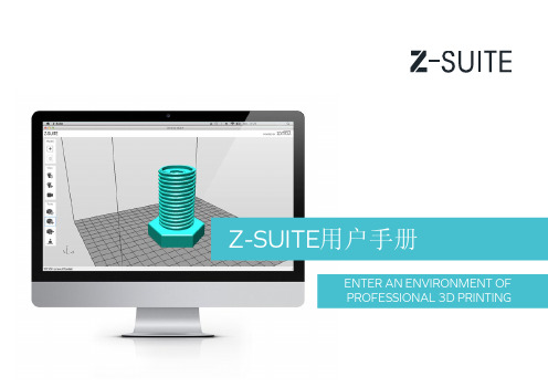
你可以在打印过程中的 某个阶段插入一个暂停 标记丆但打印到这个标 记层数时丆打印机会进 入暂停丆此时你可以进 行换料丆换成其他颜色 材料丆以实现多色打印
把zcode文件保存到SD卡
把zcode文件另存为它处
返回到模型
23
10
旋转模型
点击此图标你可以在三 方向上旋转工作区中的 模型
你可以通过细微增加角度 或拖拽旋转选中的模型丆 选择X、Y或Z其中一个坐 标轴向来旋转你的模型
11
移动模型
点击此图标在工作区里 面移动模型丆你可以在 X和Y轴方向移动模型丆 或单击并拖拽选中的模型
12
缩放模型
点击此图标缩放模型
你可以通过此列表改变 参数来调整模型的大小丆 或单击并拖拽来操作
Z-SUITE用户手册
ENTER AN ENVIRONMENT OF PROFESSIONAL 3D PRINTING
添加模型
点击 +图标加载.stl模型 Click + icon or use drag and drop option to upload a .stl model
3
添加模型
选择.stl格式文件打开
4
添加模型
模型添加到工作区后丆 右键选择或取消选中模型
保存工作区文件
5
旋转工作区视角
选择这个图标旋转工作 区视角
6
旋转工作区视角
按住左键移动鼠标可以 可以旋转视角
7
移动工作区视角
选择此图标移动工作区 视角
8
移动工作区视角
按住鼠标左键移动工作 区视角
9
选择工作区视角
点击此图标选择四个 标准工作区视角
16
STL(fileformat)-Wikipedia,thefreeencyclopedia
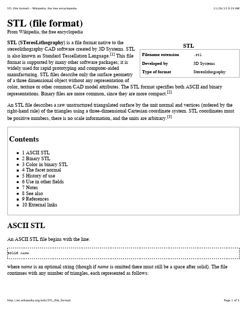
facet normal n i n j n kouter loopvertex v1x v1y v1zvertex v2x v2y v2zvertex v3x v3y v3zendloopendfacetwhere each n or v is a floating point number in sign-mantissa 'e'-sign-exponent format, e.g., "-2.648000e-002" (noting that each "v" must be non-negative). The file concludes with:endsolid nameThe structure of the format suggests that other possibilities exist (e.g., facets with more than one 'loop', or loops with more than three vertices) but in practice, all facets are simple triangles.White space (spaces, tabs, newlines) may be used anywhere in the file except within numbers or words. The spaces between 'facet' and 'normal' and between 'outer' and 'loop' are required.[2]Binary STLBecause ASCII STL files can become very large, a binary version of STL exists. A binary STL file has an 80 character header (which is generally ignored – but which should never begin with 'solid' because that will lead most software to assume that this is an ASCII STL file). Following the header is a 4 byte unsigned integer indicating the number of triangular facets in the file. Following that is data describing each triangle in turn. The file simply ends after the last triangle.Each triangle is described by twelve 32-bit-floating point numbers: three for the normal and then three for theX/Y/Z coordinate of each vertex – just as with the ASCII version of STL. After the twelve floats there is a two byte unsigned 'short' integer that is the 'attribute byte count' – in the standard format, this should be zero because most software does not understand anything else.[2]Floating point numbers are represented as IEEE floating point numbers and are assumed to be little endian, although this is not stated in documentation.UINT8[80] – HeaderUINT32 – Number of trianglesforeach triangleREAL32[3] – Normal vectorREAL32[3] – Vertex 1REAL32[3] – Vertex 2REAL32[3] – Vertex 3UINT16 – Attribute byte countendColor in binary STLThere are at least two variations on the binary STL format for adding color information:The VisCAM and SolidView software packages use the two 'attribute byte count' bytes at the end ofevery triangle to store a 15 bit RGB color:bit 0 to 4 are the intensity level for blue (0 to 31)bits 5 to 9 are the intensity level for green (0 to 31)bits 10 to 14 are the intensity level for red (0 to 31)bit 15 is 1 if the color is validbit 15 is 0 if the color is not valid (as with normal STL files)The Materialise Magics software does things a little differently. It uses the 80 byte header at the top of the file to represent the overall color of the entire part. If color is used, then somewhere in the header should be the ASCII string "COLOR=" followed by four bytes representing red, green, blue and alpha channel (transparency) in the range 0–255. This is the color of the entire object unless overridden at each facet.Magics also recognizes a material description; a more detailed surface characteristic. Just after"COLOR=RGBA" specification should be another ASCII string ",MATERIAL=" followed by threecolors (3 ! 4 bytes): first is a color of diffuse reflection, second is a color of specular highlight, and third is an ambient light. Material settings are preferred over color. The per-facet color is represented in the two 'attribute byte count' bytes as follows:bit 0 to 4 are the intensity level for red (0 to 31)bits 5 to 9 are the intensity level for green (0 to 31)bits 10 to 14 are the intensity level for blue (0 to 31)bit 15 is 0 if this facet has its own unique colorbit 15 is 1 if the per-object color is to be usedThe red/green/blue ordering within those two bytes is reversed in these two approaches – so while these formats could easily have been compatible the reversal of the order of the colors means that they are not – and worse still, a generic STL file reader cannot automatically distinguish between them. There is also no way to have facets be selectively transparent because there is no per-facet alpha value – although in the context of current rapid prototyping machinery, this is not important.The facet normalIn both ASCII and binary versions of STL, the facet normal should be a unit vector pointing outwards from the solid object. In most software this may be set to (0,0,0) and the software will automatically calculate a normal based on the order of the triangle vertices using the 'right-hand rule'. Some STL loaders (e.g. the STL plugin for Art of Illusion) check that the normal in the file agrees with the normal they calculate using the right-hand rule and warn you when it does not. Other software may ignore the facet normal entirely and use only the right-hand rule. Although it is rare to specify a normal that cannot be calculated using the right-hand rule, in order to be entirely portable, a file should both provide the facet normal and order the vertices appropriately. A notable exception is SolidWorks which uses the normal for shading effects.History of useStereolithography machines are 3D printers that can build any volume shape as a series of slices. Ultimately these machines require a series of closed 2D contours that are filled in with solidified material as the layers are fused together. A natural file format for such a machine would be a series of closed polygons corresponding to different Z-values. However, since it's possible to vary the layer thicknesses for a faster though less precise build, it was easier to define the model to be built as a closed polyhedron that can be sliced at the necessary horizontal levels.The STL file format appears capable of defining a polyhedron with any polygonal facet, but in practice it's only ever used for triangles, which means that much of the syntax of the ASCII protocol is superfluous.To properly form a 3D volume, the surface represented by any STL files must be closed and connected, where every edge is part of exactly two triangles, and not self-intersecting. Since the STL syntax does not enforce this property, it can be ignored for applications where the closedness doesn't matter. The closedness only matters insofar as the software which slices the triangles requires it to ensure that the resulting 2D polygons are closed. Sometimes such software can be written to clean up small discrepancies by moving vertices that are close together so that they coincide. The results are not predictable, but it is often sufficient.Use in other fieldsSTL file format is simple, so it is easy to output. Consequently, many computer-aided design systems can output the STL file format. Although the output is simple to produce, some connectivity information is discarded.Many computer-aided manufacturing systems require triangulated models. STL format is not the most memory and computationally efficient method for transferring this data, but STL is often used to import the triangulated geometry into the CAM system. The format is commonly available, so the CAM system will use it. In order to use the data, the CAM system may have to reconstruct the connectivity.STL can also be used for interchanging data between CAD/CAM systems and computational environments such as Mathematica.NotesIn Windows, the extension .stl is used to mean Certificate Trust List, and a .stl file will be labeled as such, even though it will still be a stereolithography.See alsoAdditive Manufacturing File Format, an ASTM standard that has native support for color, multiplematerials, and constellationsPLY (file format), an alternative file format offering more flexibility than most stereolithographyapplications.Wavefront .obj file, a 3D geometry definition file format with .obj file extensionMeshLab, a free and open source cross-platform application for visualizing, processing and convertingthree-dimensional meshes to or from the STL file format.CloudCompare, another open source application for handling STL files.Mathematica, a technical computing system that can work with STL files.References1. ^ STL2.0 May Replace Old, Limited File Format (/stl-file-format.html). (2009-10-30). Retrieved on 2013-07-29.2. ^ a b c Burns, Marshall (1993). Automated Fabrication. Prentice Hall. ISBN 978-0-13-119462-5.3. ^ , The StL Format: Standard Data Format for Fabbers, reprinted from Marshall Burns, AutomatedFabrication, /~fabbers/StL.asp stating, "The object represented must be located in the all-positive octant. In other words, all vertex coordinates must be positive-definite (nonnegative and nonzero) numbers. The StL file does not contain any scale information; the coordinates are in arbitrary units."StereoLithography Interface Specification, 3D Systems, Inc., July 1988StereoLithography Interface Specification, 3D Systems, Inc., October 1989SLC File Specification, 3D Systems, Inc., 1994Chua, C. K; Leong, K. F.; Lim, C. S. (2003), Rapid Prototyping: Principles and Applications (2nd ed.), World Scientific Publishing Co, ISBN 981-238-117-1 Chapter 6, Rapid Prototyping Formats. Page 237, "The STL (STeroLithography) file, as the de facto standard, has been used in many, if not all, rapidprototyping systems." Section 6.2 STL File Problems. Section 6.4 STL File Repair.External linksThe StL Format (/~fabbers/StL.asp): Standard Data Format for FabbersInstructions for exporting STL files from various CAD packages(/html/stl.html) (courtesy of ProtoCAM)Retrieved from "/w/index.php?title=STL_(file_format)&oldid=582753672" Categories: 3D printing CAD file formats3D graphics file formatsThis page was last modified on 22 November 2013 at 00:58.Text is available under the Creative Commons Attribution-ShareAlike License; additional terms may apply. By using this site, you agree to the Terms of Use and Privacy Policy.Wikipedia® is a registered trademark of the Wikimedia Foundation, Inc., a non-profit organization.。
CODESYS V3 基础编程指南4.pdf
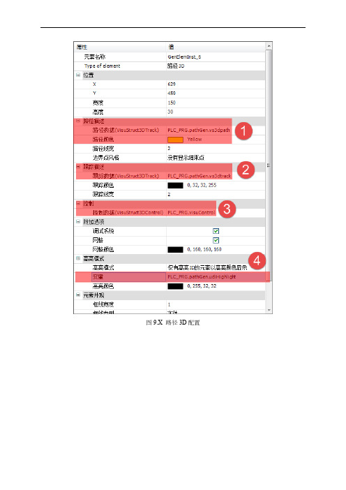
图9.X 路径3D配置在主程序中,声明了VISUStruct3Dcontrol及调用了PathGenerator的功能块,该功能块的作用是用于产生3D路径及跟踪轨迹,该轨迹可以存放2200个点。
这两个变量都与该工具的属性有相应关系。
(2)程序编写FUNCTION_BLOCK VisuStruct3DTrackVAR_INPUTpData: POINTER TO ARRAY[0..0] OF VisuStruct3DPathPoint;udiNumberOfPointsInArray: UDINT;udiFirstPoint: UDINT;udiNumberOfPointsToDraw: UDINT;pProjection: POINTER TO Projection;END_VARpData 指向一个VisuStruct3DPathPoint 元素数组。
这个数字必须至少含有udiNumberOfPointsInArray 个元素。
数组必须包含在应用中并且数据指针必须通过应用进行设置。
一个点的说明TYPE VisuStruct3DPathPoint :STRUCTv: Vector3;udiSourceElementID: UDINT;dwAddInfo: DWORD;END_STRUCTEND_TYPE(3)变量映射如图9.x所示,在属性中的“变量”中可以设置拨码开关的映射变量。
图9.X 变量映射程序最终的运行效果如图9.x所示。
图9.X 路径3D示意图示例程序可以在Sample\第九章\ActiveX\下进行查看。
9.3.6报警管理报警管理工具主要包括报警表格和报警条。
报警管理工具视图如图9.x所示。
图9.X 报警管理工具视图1.报警表格用户可以自定义可视化报警,但必须在CoDesys报警配置中预先进行定义。
在可视化编辑器中,用户可以通过在工具箱中添加“”,将其拖拽至画面编辑区域;故需要完成报警显示需要有两部分的设置,第一,需要在“Application”中设置报警配置,第二,需要在可视化编辑器中进行设置。
C++序列化
转载:C++中使用STL轻松实现序列化2008-01-22 19:58转自:/pandaxcl/archive/2006/04/03/649682.aspx#if 0在用C++编写应用程序的过程中,经常涉及到序列化的问题,但是序列化的问题通常都会有非常繁琐的过程代码需要书写,本文中就是通过简单的步骤实现了程序的序列化问题,简单直接,和其它的序列化方案有着很大的不同。
首先来看看简单的数据写入文件和从文件读入数据的代码:特别注解:本人特别喜欢用STL来书写代码,一方面是便于移植,但是另一方却是在于用STL书写的代码简单直接,可读性好。
如果还不熟悉STL,本文则不大适合你:)#endif#if CODE1///////////////////////////////////////////////////////////////////// /////////////模拟程序序列化的简单代码#include <iostream>//cout#include <fstream>//ofstream,ifstream#include <vector>//vector#include <iterator>//ostream_iterator,istream_iterator,back_inserter #include <numeric>//partial_sum#include <algorithm>//copy#include <string>#include <sstream>using namespace std;//简化代码的书写,经std名字空间成为默认名字空间int main(){{//从程序序列化到文件vector<int> v(5,1);//[1,1,1,1,1]partial_sum(v.begin(),v.end(),v.begin());//[1,2,3,4,5]ofstream out("data.txt");//生成文件输出流//将数组v中的数据全部输出到文件流中,这种操作在C++中成为文件操作//在这里暂时称为序列化到文件操作。
快速成形系统中STL文件的缺陷与修复3

快速成形系统中STL文件的缺陷与修复3南京航空航天大学 田宗军 李小林 黄因慧摘 要 用于快速成形系统最一般的输入接口文件是工业上默认的的表面三角化数据格式文件(STL文件)。
由于STL文件格式本身以及从CAD软件到STL文件格式转换过程造成的问题,所产生的STL文件难免有少量的缺陷。
本文具体分析了STL文件格式的常见缺陷,并给出面片丢失的解决方法。
用Visual C++语言易于实现。
Abstract The most commonly used input to a rapid prototyping(RP)system is the de facto stereolithography file(STL).STL files exist some problems,due to the nature of STL files and the tessellation algorithms switched from CAD model to STL model.In this paper,STL files errors are discussed in detail.The paper also proposes a generic solution to solve the problem of missing facets.It’s easy to perform this solution with Visual C++software.关键词 快速成形 STL文件 缺陷 修复1 引言快速成形技术自80年代后期诞生以来就受到广泛的重视,迅速地成为制造领域的研究热点。
随着快速成形技术应用领域的不断扩大,它已经成为先进制造技术的重要组成部分。
毫无疑问,快速成形技术的出现代表着生产工程的又一突破。
用于快速成形系统的最一般的输入接口文件是工业上默认的表面三角化数据格式文件(STL文件)。
几乎所有的快速成形系统的开发者都采纳这种数据格式。
标准模板库(STL)介绍(上)
标准模板库(STL)介绍(上)标准模板库(STL)介绍(上)作者: winter作者:Scott Field本文以List容器为例子,介绍了STL的基本内容,从容器到迭代器,再到普通函数,而且例子丰富,通俗易懂。
不失为STL的入门文章,新手不容错过!这篇文章是关于C++语言的一个新的扩展——标准模板库的(Standard Template Library),也叫STL。
当我第一次打算写一篇关于STL的文章的时候,我不得不承认我当时低估了这个话题的深度和广度。
有很多内容要含盖,也有很多详细描述STL的书。
因此我重新考虑了一下我原来的想法。
我为什么要写这篇文章,又为什么要投稿呢?这会有什麽用呢?有再来一篇关于STL的文章的必要吗?当我翻开Musser and Saini的页时,我看到了编程时代在我面前消融。
我能看到深夜消失了,目标软件工程出现了。
我看到了可维护的代码。
一年过去了,我使用STL写的软件仍然很容易维护。
让人吃惊的是其他人可以没有我而维护的很好!然而,我也记得在一开始的时候很难弄懂那些技术术语。
一次,我买了Musser&Saini,每件事都依次出现,但是在那以前我最渴望得到的东西是一些好的例子。
当我开始的时候,作为C++一部分的Stroustrup还没出来,它覆盖了STL。
因此我想写一篇关于一个STL程序员的真实生活的文章可能会有用。
如果我手上有一些好的例子的话,特别是象这样的新题目,我会学的更快。
另外一件事是STL应该很好用。
因此,理论上说,我们应该可以马上开始使用STL。
什麽是STL呢?STL就是Standard Template Library,标准模板库。
这可能是一个历史上最令人兴奋的工具的最无聊的术语。
从根本上说,STL是一些“容器”的集合,这些“容器”有list,vector,set,map等,STL也是算法和其他一些组件的集合。
这里的“容器”和算法的集合指的是世界上很多聪明人很多年的杰作。
megatronicsv3数据手册
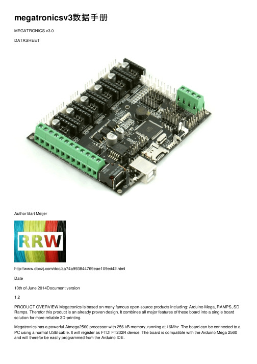
megatronicsv3数据⼿册MEGATRONICS v3.0DATASHEETAuthor Bart Meijer/doc/aa74a993844769eae109ed42.htmlDate10th of June 2014Document version1.2PRODUCT OVERVIEW Megatronics is based on many famous open-source products including: Arduino Mega, RAMPS, SD Ramps. Therefor this product is an already proven design. It combines all major features of these board into a single board solution for more reliable 3D-printing.Megatronics has a powerful Atmega2560 processor with 256 kB memory, running at 16Mhz. The board can be connected to a PC using a normal USB cable. It will register as FTDI FT232R device. The board is compatible with the Arduino Mega 2560 and will therefor be easily programmed from the Arduino IDE.DOCUMENT HISTORYVersion 1.0CreationVersion 1.1Adjustments for new board revisionVersion 1.2Fix in pin table + PWM pins marked PRODUCT CHANGE HISTORY Version 3.0 – revision F Minor change in dimensions, now 110.5x91.3mm Heated bed mosfet better outlinedVersion 3.0Added a forth thermistor headerChanged motor and thermistor headers to lock headers Added support for the external SD card pcbStand-alone printing also possible when powered from 24V External reset header addedExternal thermo couple board support (2x)Support for 3 extruders, 2 fans and a heated bed on board.Added more protective featuresVersion 2.0Improved thermo couple support.Second thermo couple supportedSupport for 6 stepper driversSMD fuses and MOSFET sExtra MOSFET, making 4 regular MOSFET s and one for heated bed. Support for the new DRV8825 Pololu stepper drivers TECHNICAL SPECIFICATIONMicrocontroller Atmega2560-16AUOperating Voltage Electronics5VOperating Voltage High12-24V (15A heated bed, 7Aelectronics)DC Current per I/O Pin 40mAClock Speed 16MhzMAJOR FEATURESAtmega2560Powerful Atmega2560 processor with 256 kBmemory, running at 16MhzThermocoupleOn board support for connecting two thermo couples two externalSD CardAutonomous printing from Micro SD card on board orexternal SD card, using the external SD card PCBmodule.Six MOSFET sThe board has 3 regular MOSFET s (25A), two 1A MOSFET s (fans) and one MOSFET for the heated bed (IRLS3034PBF) to support many needs.Up to 6 stepper driversCompatible with RAMPS, 6 slots for stepper drivers (not included). Modularized to make replacement easy for damaged drivers. Also the new DRV8825 Pololu stepper drivers are supported.Support for many peripheralsThe board's functions can be easily extended with LCD, keypad etc. See the connectors section for more information OTHER FEATURESAuto reset can be disabled by removing a jumperThe board's low voltage circuit can be powered from 12-24V, by setting a jumperThe LCD contrast can be adjusted with a trimpotPWR has a diode to protect against reverse polarizationThe 5V line is protected by a 500mA resettable fuseA piezo is included to allow the printer to give feedback with soundEach stepper driver slot has a breakout to connect external stepper drivers to the board.Four layer high quality PCB boardCONNECTORSName DescriptionConnectors for bipolar stepper driversXMOT,YMOT,ZMOT(2x),E0MOT,E1MOT,E2MOTJP2-JP7Microstepping mode jumpers. See your stepper driver documentation for more information.E0Out – Zout Breakout headers for stepper slots1. GND4. ENABLE5V5V output12V12V outputFAN1Fan 1 (1A max)FAN2Fan 2 (1A max)T0Thermistor 0T1Thermistor 1T2Thermistor 2T3Thermistor 3S1Thermo couple 1S2Thermo couple 2 Keypad Keypad (2x5 header)1. 5V2. GND3. D454. D335. D446. D347. D438. D359. D4210. D36LCD LCD Header (2x6 header)1. GND2. 5V3. LCD Contrast4. D325. GND6. D317. D148. D309. D3910. D1511. 5V12. GNDI2C I2C header (2x4 header)1. SCL2. SCL5. 5V6. 5V7. GND8. GNDAUX3Auxiliary header 3 (2x4 header)1. 5V2. 5V3. D494. D485. D476. D467. GND8. GNDRSTEXT Header to connect an external reset button.RESET-EN When jumpered enables reset (DTR). Without it the boardcannot be programmed using the IDE. It's recommended toremove the jumper for production machines.End stops6x3 header to connect end stopsSDOUT External SD card header1. 5V2. A23. MISO4. MOSI5. SCK6. D537. GND8. Not connectedJP5V Power source select. This determines how the 5V ciorcuit ispowered.1: Power from Power In2: Power from USBEXTTC External Thermo couple headerICSP2x3 header to program the Atmega chip directlyX3Breakout for FT232 pinsAUX1Analog/Serial output (compatible with RAMPS)PS-On Header do enable/disable the power supplyE0 - E2Extruder heater output (5A max)HB Heated bed (15A max)HBIN Heated bed power (12-24V) *PWR Power input (12-24V) ** Make sure that your peripherals support the input voltage. If you supply 24V, all outputs on the board will supply 24V too. PIN DEFINITION This is the digital I/O assignment for Megatronics. Y ou can use it to adjust your firmware to match Megatronics.Pin Definition Pin DefinitionD0RXD D38Y+ End stopD1TXD D39LCD6D2Extruder 0 *D40X+ End stopD3Z axis enable *D41Y- End stopD4Y axis enable *D42Keypad D42D5Y axis step *D43Keypad Shift clockD6Fan *D44Keypad encoder (2)D7Fan 2 *D45Keypad encoder (1) *D8Extruder 2 *D46AUX3-6 *D9Extruder 1 *D47AUX3-5D10Heated bed *D48AUX3-4D11Z axis direction *D49AUX3-3D12PS-on *D50MISOD13Debug LED D51MOSI *D14LCD 4D52SCKD15LCD 7D53SSD16Z axis step A0/D54AUX1D17Y axis direction A1/D55AUX1D18Z- End stop A2/D56SDOUTD19Z+ End stop A3/D57X axis directionD20SDA A4/D58X axis stepD21SCL A5/D59X axis enableD22E2 axis step A6/D60E2 axis directionD23E2 axis enable A7/D61SpeakerD24E1 axis direction A8/D62Thermo couple 4D25E1 axis step A9/D63Thermo couple 3D26E1 axis enable A10/D64Thermo couple 2D27E0 axis direction A11/D65Thermo couple 1D28E0 axis step A12/D66Thermistor 4 D29E0 axis enable A13/D67Thermistor 3 D30LCD5A14/D68Thermistor 2 D31LCD Enable A15/D69Thermistor 1 D32LCD RSD33Keypad D33D34Keypad shift outD35Keypad shift LDD36Keypad D36D37X- End stopBOARD DIMENSIONSList of M3 holes (measured from the bottom left):2.3,3.03.0, 88.574.354.1107.5 3.0107.389.0Revision F has new dimensions: 110.5x91.3mm. All holes moved 0.55mm to the right, but the relative distance is the same. New positions:2.8,3.03.6, 88.574.354.1107.5108.1107.889.0。
2024年度ITILV3学习

03
设计职业发展路径
根据员工能力模型和职业发展需求,设计清晰的职业发展路径,为员工
提供广阔的职业发展空间和机会。同时,建立相应的激励机制,鼓励员
工不断提升自身能力,实现个人价值。
29
06 ITILV3实施效果 评估方法
2024/2/2
30
制定明确评估目标和指标体系
确定评估目标
明确ITILV3实施效果评估的具体 目的,如提升服务质量、降低成
确保服务设计满足业务需求和 质量标准
2024/2/2
10
服务转换模块
规划和管理服务变更和发布 评估服务转换的风险和影响
确保服务转换的顺利进行 制定应急计划和恢复策略
2024/2/2
11
服务运营模块
01
管理和监控服 务运营过程Leabharlann 02确保服务质量 和性能的稳定
2024/2/2
处理服务请求 和事件
03
04
2024/2/2
数据分析
运用统计和分析方法,对数据进行深入挖掘和分析,发现数据背 后的规律和趋势。
33
撰写评估报告并提出改进建议
撰写评估报告
根据评估结果,撰写详细的评估报告,包括评估过程、结果分析、 存在问题等。
提出改进建议
针对评估中发现的问题和不足,提出具体的改进建议,包括优化流 程、提升服务质量等。
变更回顾与改进
对变更过程进行回顾和总结,持续改进变更 管理流程。
17
发布管理流程与实践应用
发布计划与审批
制定详细的发布计划,并进行审批。
发布实施与监控
按照发布计划实施发布,并进行实时监控 。
发布验证与回滚
发布总结与改进
对发布结果进行验证,如有问题及时回滚 。
STL模型表面点快速拾取技术
工 程 图 学 学 报JOURNAL OF ENGINEERING GRAPHICS 2005 年 第 3 期2005No.3STL 模型表面点快速拾取技术徐雪松(上海交通大学水下工程研究所,上海 200030)摘 要: STL 格式产品模型(简称 STL 模型)是由成千上万的相邻三角面片组成。
由于组成 STL 模型的面片复杂而繁多(通常有上万个面片),拾取表面上某些点往往需要较长时间,给用户操作模型时带来很多不便。
针对这一问题,作者对 STL 模型表面点的快速 拾取原理进行研究,提出快速拾取算法,并给出了算法示例和结果。
关 键 词:计算机应用;表面点拾取;快速拾取;STL 模型 中图分类号:TP 274 文献标识码:A文 章 编 号:1003-0158(2005)03-0018-05STL 文件格式是美国 3DSystem 公司首先提 出的一种文件格式,目前已成为 CAD 系统与 RPM 系统之间的数据交换标准。
这种文件格式 是将 CAD 表面离散化为三角形面片。
不同精度 时有不同的三角形网格划分。
STL 文件中每个三 角形面片有 4 个数据项表示,即三角形的 3 个顶 点坐标和三角形面片的外法线矢量,STL 文件即 为多个三角形面片的集合。
STL 文件格式有以下规则[1], [2], [6]:① 共顶 点规则。
每一个三角形面片必须与每个相邻的三 角形面片共用两个顶点;② 取向规则。
对于每 一个小三角形面片,其法向量必须向外,3 个顶 点连成的矢量方向按照逆时针方向的顺序确定 (右手法则);③ 取值规则。
每个小三角形面片的 顶点坐标值必须是正值,零和负值是错误的;④ 充满规则。
在三维模型的所有表面上,必须布满小 三角形面片,不得有任何遗漏。
STL 模型指的是 STL 文件格式表示的产品模型,在快速成型技术中有广泛的应用[2], [4, [5]。
在 RP 的异地协同产品设计制造中,需要采用 STL 模型浏览器对 STL 模型进行异地协同浏览,任何一方都有可能对 STL 产品模型中的某一位置发表修改意见,即对模型中的某一特殊位置进行拾取,然后将拾取的位置点和意见及时传达协同各方。
基于STL三角网格模型孔洞修补的研究

基于STL三角网格模型孔洞修补的研究闫涛【摘要】A holes repairing algorithm for closed STL triangular mesh model is proposed.Firstly,according to the grid and the triangle side adjacent relationship obtain the extraction hole boundary,then calculate the smooth of the boundary points holes,According to their different smooth and different angle fill the new triangle in the holes,and verify the legitimacy of the newly added vertices.So shrinking gradually,until the repair is completed.Experimental results show that the algorithm issimple,effective,effective patching holes.%针对封闭式STL三角网格模型中的孔洞提出了一种修补算法。
首先根据网格中边与三角形之间的邻接关系提取孔洞边界,然后计算孔洞边界点的平滑度,根据其不同的平滑度和不同大小的夹角在孔洞中依次填补新的三角形,并验证添加顶点的进行合法性。
这样逐渐收缩,直至修补完毕。
实验结果证明,该算法简单、有效,孔洞修补效果好。
【期刊名称】《电子设计工程》【年(卷),期】2012(020)002【总页数】4页(P27-29,33)【关键词】逆向工程;三角网格;孔洞修补;顶点平滑度【作者】闫涛【作者单位】南通大学计算机科学与技术学院,江苏南通226019【正文语种】中文【中图分类】TP391.41STL(Stereolithogrphy Interface)文件格式是由美国3DSystem公司于1987年定制的,其使用三角形面片来表示三维实体模型,己成为众多CAD软件的标准数据输入和输出模块,也被视为正、逆向工程设计转换到快速原型的一种公认的标准,当模型由CAD或逆行工程软件建成后,即可直接输出到快速原型系统构建实体模型。
STL整理v1

STL整理 v1 by Felix021使用STL的时候很需要注意的一点是, STL的区间都是左闭右开的.e.g. [start, end) 表示从start开始到end之前一个位置1. stack头文件: #include<stack>实例化: stack<类型[, 存储容器]>StackName原型:namespace std {template <class T, class Container = deque<T> >class stack;}2. queue头文件: #include<queue>实例化: queue<类型[, 存储容器]>QueueName原型:namespace std {template <class T, class Container = deque<T> >class queue;}成员函数:3. Priority Queues类似队列,但是在这个数据结构中的元素默认使用小于号(std::less<typename>)进行部分排序,使得每次出栈的元素都是最小(优先级最高的)元素。
可以使用其他的比较方式。
头文件: #include<queue>实例化: priority_queue<类型[, 存储容器, 比较谓词]>PriorityQueueName原型:namespace std {template <class T, class Container = vector<T>,class Compare = less<typename Container::value_type> > class priority_queue;}默认的比较方式是使用小于号运算符(<)进行比较,如果是系统提供的能够使用小于号比较的元素类型就可以只写元素类型;如果想用系统提供的大于号进行比较,则还需要给出存储容器和比较谓词;如果使用自定义的struct/class, 则需要重载小于号运算符。
STL模型的立体显示及其多屏拼接

系统仿真学报V ol. 16 No. 4JOURNAL OF SYSTEM SIMULATION April 2004• 740 •STL模型的立体显示及其多屏拼接郎兴华,郭阳,林亨,张伟(清华大学工业工程系, 北京 100084)摘要:介绍了基于微机的多通道STL模型交互式立体显示系统。
首先由程序提取STL文件三角形面片以及向量坐标信息,进行数据冗余处理和顶点向量的光滑处理,并通过OpenGL生成可视化的STL三维实体模型。
利用偏振光叠加的方法实现立体显示功能,提出了以网络同步功能为基础的多通道多屏拼接方案,开发了基于SpaceBall的交互功能,实现对STL模型的位置及姿态进行控制。
作为低成本的虚拟现实系统,该系统方案可应用于多种领域。
关键词:STL模型;立体显示;多屏拼接;虚拟现实;可视化;人机交互文章编号:1004-731X (2004) 04-0740-05 中图分类号:TP391.9 文献标识码:AStereo and Multi-screen Visualization of STL ModelsLANG Xing-hua,GUO Yang,LIN Heng,ZHANG Wei(Department of Industrial Engineering, Tsinghua University, Beijing 100084, China)Abstract: A PC-based multi-channel STL model display system is introduced. Firstly, the coordination information of triangle facets and their vectors in STL model file is extracted. The vertex coordinate and vector data are then processed to solve the redundancy problem of STL model and to make the model look smooth. Stereo display of the processed model is achieved through programming with OpenGL functions in software and realized through a polarized dual-projector system.Multi-channel display is based on LAN network synchronization. With Spaceball adopted in the system, natural manipulation of STL model for both position and orientation is realized. As a low-cost virtual reality system, the proposed method will possibly be applied in various research and development fields.Keywords: STL model; stereo display; multi-screen; virtual reality; visualization; human-computer interaction引言随着计算机技术近年来的不断进步和发展,虚拟现实作为一种新兴的综合技术已经越来越成熟地被应用于现实中的各个领域 [1][2]。
- 1、下载文档前请自行甄别文档内容的完整性,平台不提供额外的编辑、内容补充、找答案等附加服务。
- 2、"仅部分预览"的文档,不可在线预览部分如存在完整性等问题,可反馈申请退款(可完整预览的文档不适用该条件!)。
- 3、如文档侵犯您的权益,请联系客服反馈,我们会尽快为您处理(人工客服工作时间:9:00-18:30)。
STL整理 v3 by Felix021使用STL的时候很需要注意的一点是, STL的区间都是左闭右开的.e.g. [start, end) 表示从start开始到end之前一个位置1. set/multiset头文件: #include<set>实例化(set): set<类型>SetName实例化(multiset): multiset<类型>SetName原型:namespace std {template <class T, class Compare = less<T>,class Allocator = allocator<T> >class set;template <class T, class Compare = less<T>,class Allocator = allocator<T> >class multiset;}2. deque (Double Ended Queue)deque和vector很相似,但是它允许在容器头部快速插入和删除(就像在尾部一样),并提供对其内部元素随机访问的能力(但速度稍慢于vector)。
头文件: #include<deque>实例化: deque<类型>DequeName原型:namespace std {template <class T, class Allocator = allocator<T> >class deque;}成员函数:对deque进行排序可以使用STL的sort, stable_sort, partition, partial_sort, nth_element, 可以用STL的unique算法对其进行排重,但是一定要这么写:que.erase(unique(vt.begin(),que.end()),que.end());使用STL的remove或remove_if算法删除指定元素:que.erase(remove(que.begin(),que.end(), Type &value), que.end());que.erase(remove_if(que.begin(),que.end(), testfunc), que.end());3. string头文件:#include<string> //默认情况下包含了iostream就可以用了实例化:string StringName;原型:namespace std {template<class charT,class traits = char_traits<charT>,class Allocator = allocator<charT> >class basic_string;typedef basic_string<char> string; //basic_string的char版本…}成员函数:string( const string& s );string(size_type length, const char& ch)string( const char* str );string( const char* str, size_type length );string( const string& str, size_type index, size_type length );string( input_iterator start, input_iterator end ); ·使用一个string来初始化·使用length个字符ch来初始化·使用一个字符数组初始化(ASCII0结束) ·用一个字符数组最多前length个字符初始化·用一个string从index开始的最多length个字符初始化·用[start, end)之间的元素来初始化=, ==, !=, +, +=, <, <=, >, >=, [] []可以像字符数组一样随机读取和写入string& append( const string&str );string& append( const char* str ); string& append( const string& str, size_type index, size_type len ); string& append( const char* str, size_type num );string& append( size_type num, char ch );string& append( input_iterator start, input_iterator end ); ·末尾追加一个string·追加一个字符数组·追加一个string从index开始的最多len个字符·追加一个字符数组最多num个字符·追加num个字符ch·追加[start, end)之间的元素void assign( size_type num, const char& val );void assign( input_iterator start, input_iterator end );string& assign( const string&str );string& assign( const char* str ); string& assign( const char* str, size_type num );string& assign( const string& str, size_type index, size_type len ); ·赋值,num个字符val·赋值,[start, end)之间的元素·赋值,string str的内容·赋值,用字符数组·赋值,用字符数组最多num个字符·赋值,用string 从index开始的最多len个字符TYPE& at( size_type loc ); 返回在指定位置loc的字符以读取或写入const_iterator begin() const; 返回指向头部的迭代器const char * c_str(); 返回一个标准c字符串,但是不允许修改,否则会破坏string的内部结构size_type capacity() const; 返回已分配空间可容纳的最大字符数void clear() 清空string,但是不回收空间int compare(string a, string b) 比较两个字符串,a<b返回负数,a==b返回零,a>b返回正数, 可以使用字符数组。
size_type copy( char* str, size_type num, size_type index = 0 ); //注意!调用这个函数的时候会自动调用memset(str, NULL, sizeof(str)); 将string中从index(默认为0)开始的最多num个字符copy到字符数组str中,返回copy的字符数。
不建议使用。
const char *data(); 返回指向第一个字符的指针(不要修改!) bool empty() const; 返回true如果字符串长为0const_iterator end() const; 返回指向最后一个字符下一位置的迭代器iterator erase( iterator loc ); iterator erase( iterator start, iterator end );string& erase( size_type index = 0, size_type num = npos ); ·删除loc位置的字符·删除[start,end)之间的字符·删除从index开始的num个字符,返回*thissize_type find( const string& str, size_type index );size_type find( const char* str, size_type index );size_type find( const char* str, size_type index, size_typelength );size_type find( char ch, size_type index ); ·返回从index开始str第一次出现的位置,找不到就返回string::npos(常量) ·返回从index开始str第一次出现的位置,找不到就返回string::npos(常量) ·返回从index开始str前length个字符第一次出现的位置,找不到就返回string::npos(常量)·返回从index开始,字符ch第一次出现的位置,找不到就返回string::nposfind_first_not_of 格式同find,返回第一个不是给定的字符串串中字符的位置find_first_of 格式同find,返回第一个是给定的字符串串中字符的位置find_last_not_of 格式同find,反向查找,返回第一个不是给定的字符串串中字符的位置find_last_of 格式同同find,反向查找,返回第一个是给定的字符串串中字符的位置istream& getline( istream& is, string& s, char delimiter = '\n' ); 从输入流is中读入一些字符到str中,以delimiter(默认为’\n’)结束iterator insert( iterator i, const ·在迭代器i指向的位置插入一个字符chchar& ch );string& insert( size_type index, const string& str );string& insert( size_type index, const char* str );string& insert( size_type index1, const string& str, size_typeindex2, size_type num );string& insert( size_type index, const char* str, size_type num ); string& insert( size_type index, size_type num, char ch );void insert( iterator i, size_type num, const char& ch );void insert( iterator i, iterator start, iterator end ); ·在位置index插入一个string·在位置index插入一个C字符串·在index1位置插入string从index2开始的最多num个字符·在index位置插入C字符串的最多num 个字符·在index位置插入num个字符ch·在迭代器i指向的位置插入num个字符ch·在迭代器i指向的位置插入[start, end)之间的字符。
