UZT1V101MCL中文资料
使用说明书 合众电气

HZGZ-711电缆寻点、故障定位仪使用手册武汉市合众电气设备制造有限公司欢迎使用武汉市合众电气设备制造有限公司产品尊敬的顾客感谢您使用本公司的产品。
在您初次使用设备前,请您详细地阅读本使用说明书,将可帮助您熟练地使用我公司设备。
我们的宗旨是不断地改进和完善公司的产品,因此您所使用的设备可能与使用说明书有少许的差别。
如果有改动的话,我们会用附页方式告知,敬请谅解!您有不清楚之处,请与公司售后服务部联络,我们定会满足您的要求。
由于试验设备均有可能带电压,您在插拔测试线、电源插座时,会产生电火花,小心电击,避免触电危险,注意人身安全!◆慎重保证本公司生产的产品,在发货之日起三个月内,如产品出现缺陷,实行包换。
三年内如产品出现缺陷,实行免费维修。
三年以上如产品出现缺陷,实行有偿终身维修。
如有合同约定的除外。
◆安全要求请阅读下列安全注意事项,以免人身伤害,并防止本产品或与其相连接的任何其它产品受到损坏。
为了避免可能发生的危险,本产品只可在规定的范围内使用。
只有合格的技术人员才可执行维修。
—防止火灾或人身伤害使用适当的电源线。
只可使用本产品专用、并且符合本产品规格的电源线。
正确地连接和断开。
当设备连线处联机状态时,请勿随意连接或断开测试导线。
产品接地。
本产品除通过电源线接地导线接地外,产品外壳的接地柱必须接地。
为了防止电击,接地导体必须与地面相连。
在与本产品做联机试验前,应确保本产品已正确接地。
注意所有终端的额定值。
为了防止火灾或电击危险,请注意本产品的所有欢迎使用武汉市合众电气设备制造有限公司产品额定值和标记。
在对本产品进行连接之前,请阅读本产品使用说明书,以便进一步了解有关额定值的信息。
请勿在无产品盖板时操作。
如盖板或面板已卸下,请勿操作本产品。
使用适当的保险丝。
只可使用符合本产品规定类型和额定值的保险丝。
避免接触裸露电路和带电金属。
产品有电时,请勿触摸裸露的接点和部位。
在有可疑的故障时,请勿操作。
如怀疑本产品有损坏,请本公司维修人员进行检查,切勿继续操作。
第二章LMK-101系列装置使用说明-电气自动化

LMK-101 数字式通用型综合保护装置技术使用说明书V2.0江苏南自继保电力科技有限公司用户须知尊敬的用户:感谢您使用江苏南自继保电力科技有限公司生产的LMK-101数字式通用型综合保护装置。
在安装和使用本系列产品前,请您注意以下提示:◆在您收到产品后,请核对产品标签与您所订购的型号、规格是否相符,产品的额定电压、额定电流是否符合使用要求;◆请检查产品是否存在外观损伤;◆请检查配套物品是否齐全,包装箱内应包括以下物品:●LMK-101系列数字式综合保护装置 1台●产品调试及检验报告 1份●产品合格证 1份◆在安装、使用产品前请仔细阅读本说明书,严格按照本说明书所述进行安装连线,并设置使用。
本说明书无法涵盖所有场合或包含所有细节,如有特殊情况或疑问,在没有得到正确的指导前请不要做任何举措,请先联系我公司技术部询问相关信息,在得到确认后方可操作;◆该产品在测试和使用时,接地端子(120)及外壳要可靠接地;◆本产品在运行状态时,请勿用尖锐及细长的金属物品接触产品的空隙部分,以免触电、造成产品的损坏或保护误动作;◆请使用合格的测试仪器和设备对装置进行试验和检测;◆产品安装完毕后,请仔细检查接线,确定正确后方可通电调试,以免造成产品的损坏;◆产品出厂时的预置密码是“0000”,此密码可在“装置参数→修改密码”菜单中修改,修改后请注意保存,以免遗失;◆不可在产品运行状态下进行出口传动或修改保护定值的操作,以免造成装置误动作;◆定值整定时要按照“先整定定值,后投入保护功能”的顺序进行;◆本说明书由江苏南自继保电力科技有限公司出版,并对所示产品保留最终解释权;◆本说明书所示产品日后会有小改动,请注意核对实际产品及相关说明书;江苏南自继保电力科技有限公司 2012 年12月1目录第一章LMK-101数字式通用型综合保护装置 (4)1.1简介 (4)1.2装置功能 (4)1.3装置原理 (4)1.3.1速断保护功能 (4)1.3.2 过流保护功能 (5)1.3.3 过流加速保护 (5)1.3.4 过负荷报警 (6)1.3.5 过流反时限保护 (6)1.3.6 负序过流保护 (6)1.3.7 零序保护 (7)1.3.8 过电压保护 (7)1.3.9 低电压保护元件 (7)1.3.10 非电量保护 (8)1.3.11 CT断线告警 (8)1.3.12 相序报警 (8)1.3.13 PT断线告警 (8)1.3.14 开关位置异常告警 (8)1.3.15 弹簧未储能报警 (8)1.3.16 通信 (8)1.4定值及整定说明 (9)1.4.1 LMK-101整定值清单及说明 (9)1.4.2 LMK-101参数清单及说明 (10)21.4端子及接线原理图 (11)第二章LMK-101系列装置使用说明 (14)2.1装置外观说明 (14)2.1.1 面板布局 (14)2.1.2 液晶 (14)2.1.3 指示灯 (14)2.1.4 键盘按键 (15)2.1.5 装置机箱开孔尺寸图 (15)2.2菜单操作说明 (17)2.2.1 菜单说明 (17)2.2.2 中文主菜单 (17)2.2.3正常显示画面 (19)2.2.4主菜单操作说明 (19)2.2.5状态显示 (20)2.2.6装置参数 (20)2.2.7装置记录 (23)2.2.8就地控制 (24)2.2.9版本信息 (25)2.2.10复位装置 (25)3第一章LMK-101数字式通用型综合保护装置1.1简介LMK-101数字式通用型综合保护装置是我公司为适应我国电气成套事业发展的需要,积累多年电力自动化产品开发经验,吸收国内外先进技术,向广大电力成套厂商推出的一款经济性综合保护装置。
PCU1系列主要用于主电路注入、稳定性测试和电路断路器测试的中央控制器说明书

The control units are rated at 11.5kVA with a 2 second overload capability of 23kVA using pulse mode. All metering is digital and a memory facility is provided to hold the current reading when the output trips or is switched off. The current is thyristor controlled and is automatically switched off when the device under test trips.The PCU1 systems have a high accuracy timing system, allowing timing tests to be carried out to a resolution of 1ms. Selection for normally open or normally closed contacts is automatic, and the status of the contacts is shown on the front panel.The PCU1 series aremedium powered primary currentinjection systems offering output currents up to 5000A. The system consists of a separate control unit containing all metering and control functions and a loading unit that provides the high current output. The PCU1-LT and PCU1-SP are ideally suited to primary current injection, stability testing and circuit breaker testing. In addition, the SP version offers direct-reading CT ratio and polarity tests and a 100A secondary injection output. T&R also offer the higher-powered PCU1-HP and PCU2.Features (PCU1-LT and PCU1-SP) •5kA maximum output current (higher overload currents for 2s) •Multi-function digital timing system •Digital true RMS memory ammeter •Solid state switching•2000A and 5000A loading units •Three range outputs on loading units •Rugged, compact design•Optional trolley mounting of system PCU1-SP Additional Features•Secondary injection up to 100A •Direct reading CT ratio and polarityTiming modes are available to test under and over current devices, re-closers, under and over voltage devices, current trips and circuit breakers. A full range of high current output leads are available to complement the system in a range of lengths.Two loading units are available, delivering a maximum outputcurrent of 2000A or 5000A. Each loading unit has three output taps to allow for a wide range of load impedances. For example, the NLU5000 may be configured to either give a maximum current of 5000A on the 2.3V range, 2500A on the 4.6V range or 1250A on the 9.2V range.PCU1-SP PCU1-LTPrimary Current Injection SystemsPCU1-SP & NLU5000 withoptional trolleyFeature PCU1-LTPCU1-SPPCU2 Primary injection ü ü ü Max output power 11.5kVA 40s11.5kVA 40s 20kVA 5 min Secondary injection û ü û CT ratio/polarity testûüûOutput current Range Output state1.000kA 5kA On 000.000s 5000.:5ACTTimerAuxiliary metering23Note: Due to the company’s continuous research programme, the information above may change at any time without prior notificatio n. Please check that you have the most recent data on the product.T&R Test Equipment Ltd, 15-16 Woodbridge Meadows, Guildford, Surrey, GU1 1BJ, UKTel:+44(0)1483207428Fax:+44(0)1483511229email:****************PCU-LT/PCU1-SP Control Unit SpecificationLoading Unit Current MeteringThe AC output current is metered by a true RMS memory ammeter (acquisition time 200ms) with a liquid crystal display. The current metering has 3 ranges corresponding to 10%, 50% and 100% of the maximum rating of the loading unit. In addition, a 200% metering range is enabled in pulse mode. NLU2000Range Full scale Resolution Accuracy 10% 200.0A 0.1A ±0.5%rdg+5d* 50% 1000A 1A ±0.5%rdg+5d* 100% 2000A 1A ±0.5%rdg+5d* 200% 4000A 1A ±1%rdg+5d** NLU5000Range Full scale Resolution Accuracy 10% 500.0A 0.1A ±0.5%rdg+5d *1 50% 2500A 1A ±0.5%rdg+5d *1 100% 5000A 1A ±0.5%rdg+5d *1 200% 10kA 10A ±1.5%rdg+5d *2 *11.5% rdg+5d in pulse mode *2selected in pulse modeTiming SystemThe PCU1 systems have a flexible timing system with two contact inputs and 5 operating modes. Each contact circuit automatically selects for N/O or N/C contacts, and the status of each contact input is shown by an LED. The timing channels may also be triggered by a dc voltage between 24 and 240V. Timer resolution 1msTimer full scale 999.999sTimer accuracy ±0.01%rdg+2d (4d current mode) Contact O/C voltage 24V Contact S/C current 20mAVdc input range 24-240VdcTimer mode Timer start Timer stop Internal Start ‘On’ button Contact Single contact Contact 1 Contact 1 Dual contact Contact 1 Contact 2 Current operated *3 Current >20% rng Current <20% rngPulse mode 0.2s *4‘On button’ 0.2s Pulse mode 0.5s *4 ‘On button’ 0.5s Pulse mode 1s *4 ‘On button’ 1s Pulse mode 2s *4 ‘On button’ 2s Off Setting position*3Current operated mode is used to time circuit breakers with no auxiliary contacts. The timer is started when the current exceeds 20% of the selected metering range (e.g. 100A on the NLU5000 500A range). The timer stops when the current falls.*4Pulse mode applies current to the load for a maximum of the specified time. If contact set 1 changes state or the current drops below 20% of the metering range during the pulse ti me, the timer is stopped. The maximum output current is increased in pulse mode. The maximum obtainable current is set by the impedance of the test object and output leads.Secondary Injection Output (PCU1-SP only)The secondary current injection output on the unit has two taps, allowing the injection of currents up to 100A. Output Range Continuous Intermittent current current 5min on *5 1 min on *5 0-5V 33A 67A 100A 0-16V 10A 20A 30A *5All on times must be followed by an off time of 15 minutesMetering Range Resolution Accuracy Current trip 10.00A 0.01A ±0.5%rdg +5d 10.5A 20.00A 0.01A ±0.5%rdg +5d 21A 100.0A 0.1A ±0.5%rdg +5d 100A The output is protected by electronic trips and a circuit breaker.Supply Requirements230V±10%, 45-65Hz 1ph 11.5kVA max (23kVA overload for 2s)Control Unit Standard AccessoriesMains lead (5m), loading unit power and metering leads (5m), operating manual and spare fuses.DimensionsPCU1-SP/PCU1-LT 450(w) x 275(h) x 305mm(d)NLU2000/NLU5000 450(w) x 275(h) x 370mm(d) incl. terminalsWeightPCU1-LT 23kg PCU1-SP 26kg NLU5000 55kg NLU2000 50kgTemperature RangeStorage -20°C to 60°C, Operating 0°C to 45°CProtection and SafetyThe PCU1 series and loading units are CE marked and are designed to meet the requirements of BS EN61010. The system is protected by electronic trips on the outputs, circuit breakers on the mains input, control unit output and secondary injection output (PCU1-SP only). The unit also has a duty cycle trip on the loading unit output and the loading unit has comprehensive thermal protection.Optional Loading Unit SpecificationsTwo loading units are available to provide a range of output currents suitable for different primary injection tasks. Each loading unit has three output taps allowing current injection into a wide range of loads of differing impedances. Optional output lead sets are also available (see for details).NLU5000 Loading Unit Intermittent RatingsOutput Maximum currentVoltage* Cont. 5 min 1 min 40s 2.3V 1500A 3000A 4500A 5000A 4.6V 750A 1500A 2250A 2500A 9.2V 375A 750A 1125A 1250ANLU2000 Loading Unit Intermittent RatingsOutput Maximum currentVoltage* Cont. 5 min 1 min 40s 3.5V 600A 1200A 1800A 2000A 6.9V 300A 600A 900A 1200A 13.8V 150A 300A 450A 500AI <20% r a n g e C o n t a c t 124 PCU1-LT-SP Data Sheet rev 4 28/12/05。
功尊 RTU-100X 智能远程终端控制柜 说明书
RTU-100X智能远程终端控制柜说明书功尊仪表(浙江)有限公司目录一、 产品概述 (1)二、 技术特点 (1)三、 工作原理 (2)四、 外观及接口 (3)4.1实物图 (3)4.2规格参数 (3)4.3内部组成 (4)4.4功能结构 (5)4.5 RTU终端 (5)五、 RTU与外围设备通讯及连接 (6)5.1仪表接入 (6)5.2安防系统接入 (8)六、 安装调试 (9)6.1外形尺寸 (9)6.2安装 (9)6.3接线 (10)6.4安装规范 (11)6.5调试 (11)6.6安装注意事项 (11)七、 常见故障分析及处理 (12)八、 质量承诺 (12)九、 运输和贮存 (12)十、 开箱及检查 (12)尊敬的用户,感谢您购买本公司RTU-100X型智能远程终端控制柜产品,为确保能够安全、可靠、正确使用本产品,请仔细阅读本使用说明书,熟悉产品操作并严格遵守说明书的要求。
一、产品概述RTU-100X型智能远程终端控制柜(以下简称控制柜),是我公司专门为燃气仪表设备远程监控而设计一款物联网终端产品,它既可直接与各种流量计、变送器等燃气仪表连接,也可接入其它环境监测设备,通过4G无线通信技术,将现场仪表和设备与远程监控中心建立无线通信链接,完成数据交换。
控制柜可以和我司自主监控平台软件(SCADA系统)配套使用,实现前端设备的远程集中监控,也可以通过协议与第三方监控平台对接实现对其的集中监控管理。
通过监控平台软件,管理人员可实现对前端设备的集中管理,远程查看现场设备的实时数据、运行情况,采用分布式应用、集中监控、统一管理的原则,减少现场的人工投入,实现无人值守的目的。
同时,监控平台软件也可以根据控制柜发送的数据,进行统计分析,提高工作效率。
控制柜安装方便,且易于操作。
目前该产品已广泛应用于燃气、水务行业物联网抄表系统及SCADA系统的项目建设。
产品执行标准:执行Q/GZ 102.02-2022《智能远程终端控制柜》企业标准本产品符合GB3836.1-2021 《爆炸性环境 第1部分:设备 通用要求》和GB3836.2-2021《爆炸性环境 第2部分:由隔爆外壳“d”保护的设备》标准;防爆标志为Ex d IIC T6 Gb,经国家防爆电气产品质检中心检验合格,取得防爆合格证。
CRIO-4010 单相、三相全参数交流 电量采集模块 用户手册说明书
CRIO-4010单相、三相全参数交流电量采集模块用户手册版本号:Q7-30-02修订日期:2016-11-1国控精仪(北京)科技有限公司2016年版权所有本软件文档及相关套件均属国控精仪(北京)科技有限公司所有,包含专利信息,其知识产权受国家法律保护,除非本公司书面授权许可,其他公司、组织不得非法使用和拷贝。
为提高产品的性能、可靠性,本文档中的信息如有完善或修改,恕不另行通知,客户可从公司网站下载或致电我们通过电子邮件索取,制造商无需作成承诺和承担责任。
客户使用产品和软件文档进行设备调试和生产时,应进行可靠性、功能性等全面测试,方可进行整体设备的运行或交付。
我们提供7*24电话技术支持服务,及时解答客户问题。
如何从国控精仪获得技术服务我们将为客户提供满意全面的技术服务。
请您通过以下信息联系我们。
国控精仪公司信息网址: 英文中文销售服务: **************销售分机:801 电话: 400 9936 400 ************传真: ************地址: 北京市海淀区安宁庄东路18号2号办公楼420-423室请将您下列的信息通过邮件或传真发送给我们1概述...................................................................................................................................... - 1 -1.1产品特性.................................................................................................................. - 1 -1.2产品应用.................................................................................................................. - 1 -1.3产品详细指标.......................................................................................................... - 2 -1.3.1电量参数...................................................................................................... - 2 -1.3.2系统稳定时间.............................................................................................. - 2 -1.3.3物理特征...................................................................................................... - 3 -1.3.4产品功耗(典型值) ..................................................................................... - 3 -1.3.5工作环境...................................................................................................... - 3 -1.3.6存储环境...................................................................................................... - 3 -1.4软件支持.................................................................................................................. - 3 -2设备安装.............................................................................................................................. - 5 -2.1产品开箱.................................................................................................................. - 5 -2.2软件安装.................................................................................................................. - 5 -2.3产品布局图.............................................................................................................. - 6 -3信号连接说明...................................................................................................................... - 7 -3.1连接器管脚分配...................................................................................................... - 7 -3.2电源与通讯连接...................................................................................................... - 8 -3.3信号连接.................................................................................................................. - 9 -4 模拟量输入(AI)模块功能码........................................................................................ - 10 -4.1读保持寄存器........................................................................................................ - 10 -4.2读输入寄存器........................................................................................................ - 11 -4.3设置单个保持寄存器............................................................................................ - 13 -4.4设置多个保持寄存器............................................................................................ - 13 -5产品注意事项、保修、校准............................................................................................ - 15 -图2-1 CRIO4010产品图................................................................................................... - 6 -图3-1 电源与通讯接线图 ................................................................................................ - 8 -图3-2 单相电示意图 ........................................................................................................ - 9 -图3-3 三相电示意图 ........................................................................................................ - 9 -表3-1 16P端子标注 .......................................................................................................... - 8 -1概述CRIO-4010是基于RS485的高性能通信模块。
罗克韦尔 Compact 5000 I O 数字量模块 说明书

基于 EtherNet/IP 的连接 . . . . . . . . . . . . . . . . . . . . . . . . . . . . . . . . . . . 56 使用 External Means 时连接的其他注意事项 . . . . . . . . . . . . . . . . 57 受限操作 . . . . . . . . . . . . . . . . . . . . . . . . . . . . . . . . . . . . . . . . . . . . . . . . . . . . . . . 58 安全模块特定注意事项 . . . . . . . . . . . . . . . . . . . . . . . . . . . . . . . . . . . . . . . . 59 整体系统安全功能 . . . . . . . . . . . . . . . . . . . . . . . . . . . . . . . . . . . . . . . . . 60 单通道或双通道模式 . . . . . . . . . . . . . . . . . . . . . . . . . . . . . . . . . . . . . . . 60 与安全控制器结合使用 . . . . . . . . . . . . . . . . . . . . . . . . . . . . . . . . . . . . 61 确定符合性 . . . . . . . . . . . . . . . . . . . . . . . . . . . . . . . . . . . . . . . . . . . . . . . . 61
Unique SSV单座型筒头控制器用户指南说明书
TEKNISET TIEDOT LämpötilaLämpötila-alue:...............10-+140°C (EPDM)PaineTuotteen enimmäispaine:.........1000kPa (10bar)Tuotteen vähimmäispaine:........Täysi tyhjiöVenttiilipesänyhdistelmätFYYSISET TIEDOT MateriaalitTuotepuolen teräsosat:..........1.4404(316L)Muut teräsosat ................1.4301(304)Ulkopinnan käsittely:............Puolikiiltävä(puhallettu)Sisäinen pintakäsittely:...........Kirkas (kiillotettu),Ra <0,8µmMuut tuotepuolen tiivisteet........EPDMLisävarusteetA.Kierreosat ja pantaliittimet vaaditun standardin mukaisesti.B.Tuotepuolen HNBR-tai FPM-tiivisteet.C.Karan HNBR-,FPM-tai TR2-tiiviste(kelluva PTFE-rakenne-vainkäsikäyttöinen venttiili).D.Kiiltäväulkopinta.HuomautusKatso lisätiedot ohjeesta ESE00307.Muita samaan perusrakenteeseen perustuvia venttiileitäVenttiilisarjassa on useita erikoisventtiilejä.Seuraavassaluettelossa on joitakin saatavilla olevista venttiilimalleista;tutustukaikkiin malleihin ja vaihtoehtoihin Alfa Lavalin tietokoneavusteisenvalintatyökalun(CAS)avulla.-Vakioventtiili.-Vastasuuntaventtiili.-Aseptinen venttiili.-Pitkäiskuinen venttiili.-Säiliön pohjaventtiili.Toimilaitteella on viiden vuoden takuu.Mitat(mm)-Käsikäyttöiset Unique-venttiilitKoko25385163.576.1101.6DN DN DN DN DN DN mm mm mm mm mm mm2540506580100 A11245245259285291337247247260284295338 A21260265284310321367262267285309325368 A31291307332371390460297312336376402464 A41303324354393417487309329358398429491 C47.860.873.886.398.9123.652647692107126 OD25385163.576.1101.62941537085104 ID21.834.847.860.372.997.62638506681100 t 1.6 1.6 1.6 1.6 1.62 1.5 1.5 1.5222 E15049.56181861195049.5627887120 E25049.56181861195049.5627887120 F1152025253030152025253030 F2121722222727121722222727 H105105105105105105105105105105105105 M/ISO panta212121212121------M/DIN panta------212121282828 M/DIN kierreosa------222223252530 M/SMS kierreosa202020242435------Paino(kg)Sulkuventtiili 1.8 2.0 2.6 3.6 4.67.0 1.9 2.1 2.5 3.7 5.0 6.9 Vaihtoventtiili 2.6 3.0 4.2 5.67.311.4 2.8 3.2 4.2 5.98.211.21)Katso tarkat A1-A4-mitat CAS:ntiedoista.TD 454-014Sulkuventtiili Vaihtoventtiili Karan PTFE-tiiviste(TR2) Kuva2.Mitat.Kv-arvotVenttiilin koko Kv38mm/DN4014*/4451mm/DN507563.5mm/DN6511376.1mm/DN80171101.6mm/DN100250*valinnainenKv=m3/h,kun painehäviöon1bar.Kun painehäviöon muuta kuin1bar,virtaus lasketaan seuraavalla kaavalla:Q=Kv x√∆pJossaQ=virtaus m3/h.Kv=ks.edellä.∆p=Painehäviöventtiilissä,bar.Esimerkki:Kara Kv75Q lasketaan∆p=2bar:Q=75x√2=106m3/htai50%iskulla:Q=0,5x75x√2=53m3/hPainehäviö-/kapasiteettikaaviotSuljinten ominaisuudet ovat lineaariset.Tämätarkoittaa,ettätiettymääräkuristamista iskua pienentämälläaiheuttaa verrannollisen virtauksen vähenemisen,jos tuotteen paine pysyymuuttumattomana. Kuva3.Virtaus,%kokonaisvirtauksesta,kun painehäviöon1bar.Mitat(mm)-Käsikäyttöiset Unique-venttiilitKoko385163.576.1101.6DN DN DN DN DNmm mm mm mm mm40506580100 A1176189215221267178191215226269 A2196214240251297198216240256299 OD385163.576.1101.641537085104 ID34.847.860.372.997.638506681100 t 1.6 1.6 1.6 1.62 1.5 1.5222 E149.561818611949.5627887120 E249.561818611949.5627887120 F120252530302025253030 H80808080808080808080 M/ISO panta2121212121-----M/DIN panta-----2121282828 M/DIN kierreosa-----2223252530 M/SMS kierreosa2020242435-----Paino(kg)-Sulkuventtiili 2.1 2.9 4.0 5.48.2 2.2 2.9 4.1 5.98.1Kuva4.MitatESE00276FI1308Tiedot vastaavat julkaisuhetken tietoja,oikeudet muutoksiin pidätetään.ALFA LAVAL on Alfa Laval Corporate AB:n rekisteröimäja omistamatuotemerkki.©Alfa LavalAlfa Lavalin yhteystiedotEri maiden ajan tasalla olevat yhteystiedotovat yhtiön verkkosivuilla.Tiedot on julkaistu osoitteessa .。
vtl用户手册

公告
本手册中描述的产品特性和规格如有更改,恕不另行通知。 由于使用或按照包含于此的信息执行而导致的任何损害或数据丢失,制造商将不负担任 何责任。
安规信息
适用于欧洲
本设备符合 EMC (电磁兼容性检验) 标准。
Federal Communications Commission (FCC) 声明
本设备经过测试,结果依据 FCC Rules Part 15之规定,符合 Class B 数字装置之标准。这 些标准的设立目的是在安装本设备的居家环境中,针对有害干扰提供合理防护。本设备产生、 使用、而且能辐射无线电频率能量,若未依据指示安装及使用,则对于无线电通讯可能造成有 害干扰,但是亦无法保证特定安装方式不会产生干扰。若本设备对于收音机或电视机的接收讯 号确实造成有害干扰;这种干扰可藉打开及关闭本设备电源加以确认;则我们鼓励使用者采取 下列措施,尝试消除干扰: 改变接收天线的方向或位置。 增加设备与接收机之间的距离。 设备与接收机使用个别的电源插座。 请联系经销商或经验丰富的广播/电视机故障,最好给存储系统配置UPS。在用UPS供电时,应保证UPS启动至少1分钟后再 接通存储系统电源,以避免UPS在刚启动时对存储子系统造成冲击。
5
目
录
序言...................................................................................................................................................1 安规信息...........................................................................................................................................1 安全警告和注意事项.......................................................................................................................2 第一章 SureSave VTL500i/1000i 介绍......................................................................................... 6 1.1 产品概述...........................................................................................................................6 1.2 接口与面板说明............................................................................................................... 7 1.3 现场可更换部件............................................................................................................... 8 第二章 硬件安装与连接.................................................................................................................9 2.1 安全注意事项...................................................................................................................9 2.2 安装条件...........................................................................................................................9 2.3 设备开箱.........................................................................................................................10 2.4 安装到机架..................................................................................................................... 11 2.5 安装磁盘.........................................................................................................................12 2.6 设备连接.........................................................................................................................13 第三章 系统配置...........................................................................................................................16 3.1 基本知识.........................................................................................................................16 3.2 系统配置概要.................................................................................................................17 3.3 基本配置步骤.................................................................................................................18 3.4 存储管理.........................................................................................................................20 3.5 虚拟磁带库管理............................................................................................................. 22 3.6 系统设置.........................................................................................................................27 第五章 注意要点及故障处理....................................................................................................... 31 5.1 注意要点.........................................................................................................................31 5.2 常见故障处理.................................................................................................................31 联系我们.........................................................................................................................................32
DC10600EW101_1VX1_X(T C N)_2 数据手册说明书
广州大彩光电科技有限公司版权所有版本记录销售与服务广州大彩光电科技有限公司电话:************-601传真:************Email:*************(咨询和支持服务)网站:地址:广州黄埔区(科学城)玉树工业园C栋3楼网络零售官方旗舰店:目录1. 硬件介绍 (1)1.1产品外观 (1)1.2硬件配置 (2)1.3调试工具 (3)2. 产品规格 (4)3. 产品尺寸 (7)4. 引脚定义 (8)5. 可靠性测试 (9)5.1ESD测试 (9)5.1.1执行标准 (9)5.1.2测试环境 (9)5.1.3测试数据 (10)5.2高低温老化测试 (10)5.2.1测试环境 (10)5.2.2测试数据 (11)5.3群脉冲测试 (11)5.3.1执行标准 (11)5.3.2测试环境 (11)5.3.3测试数据 (12)6. 产品定义 (13)7. RS232与TTL电平转换 (14)8. 包装与物理尺寸 (15)9. 产品架构 (16)10. 开发软件 (17)10.1什么是虚拟串口屏 (17)10.2Keil与虚拟串口屏绑定调试 (18)11. 开发文档 (19)12. 免责声明 (20)1. 硬件介绍本章节主要介绍产品的一些外观参考图、硬件配置图和调试所需工具。
1.1 产品外观以下为该尺寸不同型号的外观参考图,如图1-1、图1-2和图1-3所示。
注:未涉及到结构工艺修改或布局大改动,硬件可靠性方面的变更迭代,公司不予对外发起变更,具体以收到的实物为准。
图1-1 10.1寸电阻触摸参考图图1-2 10.1寸电容触摸参考图销售咨询:************-601Email:*************销售咨询:************-601Email:*************图1-3 10.1寸无触摸参考图1.2 硬件配置以下为该产品硬件配置参考图,如图1-4和图 1-5所示。
【VIP专享】PLAC-5105L使用说明书V1.3(20111114)

4.1 模拟量输出的设置技巧........................................... 11 3.2 日期时间的设置技巧............................................. 11 3.3 打印机的设置技巧............................................... 12 3.4 峰值检测的设置技巧............................................. 12
SeTAQ
PLAC-5105L 使用说明书
第一章 概述
PLAC-5105 系列称重显示控制器是山东西泰克仪器有限公司自主研发的 工业级通用称重显示控制器,能够在显示重量值的情况下,并行的将普通传 感器信号变送为 4-20mA、0-5V 或 0-10V 模拟信号,同时保持与计算机、PLC 等上位机的通信(或者是接串口打印机进行重量日期的打印,仅 PLAC-5105L 具有此功能);具有抗干扰能力强、功能强大、操作简便、通用性强、温漂小、 线性度高等特点。
PLAC-5105L 是 PLAC-5105 系列中功能最为强大的。除了具有上述功能之 外,PLAC-5105L 还具有以下强大的功能:带日历并且掉电不丢失、可接串口 打印机来打印日期时间重量和地址等信息,方便称重数据的存档。
PLAC-5105L 分为 PLAC-5105L、PLAC-5105L-I、PLAC-5105L-UI 三个 型号;其中,PLAC-5105L 型不具有 DA 输出功能,PLAC-5105L-I 型仅能输出 4-20mA 电流信号,PLAC-5105L-UI 型具有 0~5V,0~10V 电压输出、4~20mA 电流输出功能;其中以 PLAC-5105L-UI 型的功能最为强大。
usr-iot-wh-l101-l-c-lora-模块-使用说明书
LORA 模块联网找有人可信赖的智慧工业物联网伙伴说明书WH-L101-L-C目录Content 1.产品概述 (4)1.1.概述 (4)1.2.硬件描述 (5)1.3.硬件连接 (7)2.产品功能 (8)2.1.工作模式 (9)2.1.1.私有服务器 (10)2.1.1.1.A T指令模式 (10)2.1.1.2.主动上报模式 (10)2.1.1.3.轮询唤醒模式 (13)2.1.1.4.服务器下发模式 (16)2.1.1.5.特别说明 (20)2.1.2.有人云模式 (20)2.1.1.6.私有服务器+云监测模式 (20)2.1.1.7.有人云/有人云私有部署模式 (24)2.1.1.8.数据透传 (28)2.2.数据安全 (31)3.AT指令设置方法 (31)3.1. A T指令格式 (33)3.2. A T指令集 (33)3.2.1. A T+ENTM (34)3.2.2. A T+E (34)3.2.3. A T+Z (34)3.2.4. A T+CFGTF (34)3.2.5. A T+RELD (35)3.2.6. A T+CLEAR (35)3.2.7. A T+VER (35)3.2.8. A T+UART (35)3.2.9. A T+SPD (36)3.2.10. A T+AID (37)3.2.11. A T+NID (37)3.2.12. A T+CH (37)3.2.13. A T+PWR (38)3.2.14. A T+WTM (38)3.2.15. A T+PTM (38)3.2.16. A T+STM (39)3.2.17. A T+ITM (39)目录Content3.2.18. A T+RTO (40)3.3. A T指令配置工具 (40)4.联系方式 (41)5.免责声明 (41)6.更新历史 (42)1.产品概述1.1.概述WH-L101-L-C是一个支持集中器通信协议的低频半双工LoRa模块,工作的频段为:398~525MHz。
101系列用户手册讲解

串口以太网服务器MWT101/2系列用户手册(使用前请先阅读本手册)版本号:2.0.1重要声明本公司将尽可能地提供本系列产品可靠而详尽的资讯,努力使本手册中提供的信息准确和适用,然而本公司并不对这些信息的使用承担任何责任,也不对这些信息的使用承担任何连带责任。
本公司并无义务提供此系列产品详尽的应用资讯,或对因非法使用本系列产品所遭受的损害负任何责任。
本公司保留在不事先通知情况下更改本使用手册全部或部分内容的权力。
由于产品和技术的不断更新、完善,本资料中的内容可能与实际产品不完全相符,敬请谅解。
如需查询产品的更新情况,请查询本公司网站或直接与本公司业务代表联系。
商标&著作权本书提到的所有公司商标、商标名称及产品名称分别属于该商标或名称的拥有者所有。
1目录一、产品介绍 (3)1、产品概述 (3)2、简明特点 (3)3、外形图及指示灯说明 (4)4、引脚定义 (6)二、产品应用 (8)1、应用概述 (8)2、跳线说明 (9)3、接线说明 (9)4、设备配置 (11)5、设备应用 (16)1)通信帧说明 (16)2)使用方式 (17)6、安装尺寸 (19)7、常见故障排除方法 (19)三、选型指南 (21)1、电源配置 (21)2、产品型号定义 (21)2一、产品介绍1、产品概述重要设备联网是工厂企业发展的趋势。
MWT101/2系列串口以太网服务器的主要功能就是将标准的串口总线数据(RS-232、RS-422、RS-485)与标准的支持TCP/IP协议的以太网数据进行双向转换,用来解决普通串口设备在Internet/Intranet上的联网问题。
MWT101/2系列包含如下几种型号:型号说明MWT101-A 一路串口信号与以太网的双向转换,非隔离型MWT101-B 一路串口信号与以太网的双向转换,隔离型MWT102-A 二路串口信号与以太网的双向转换,非隔离型MWT102-B 二路串口信号与以太网的双向转换,隔离型以上几种型号大部分功能与特性是一致的,有不同的地方会特别说明。
莫贾 PTC-101 系列 IEC 61850-3 以太网到光纤传输媒体转换器说明书
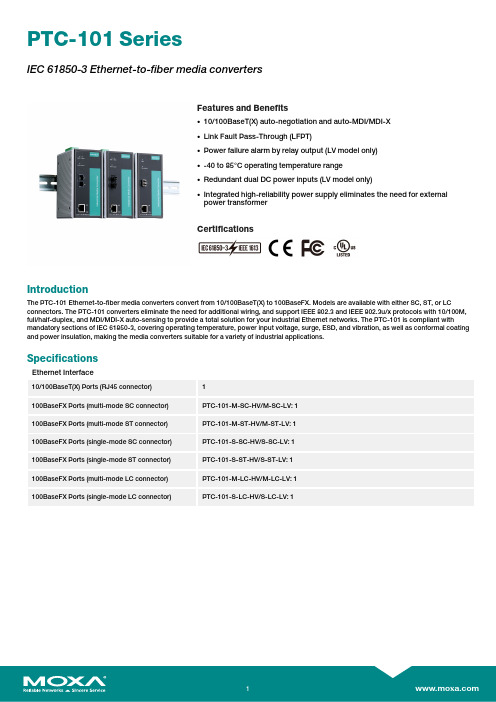
PTC-101SeriesIEC61850-3Ethernet-to-fiber media convertersFeatures and Benefits•10/100BaseT(X)auto-negotiation and auto-MDI/MDI-X•Link Fault Pass-Through(LFPT)•Power failure alarm by relay output(LV model only)•-40to85°C operating temperature range•Redundant dual DC power inputs(LV model only)•Integrated high-reliability power supply eliminates the need for externalpower transformerCertificationsIntroductionThe PTC-101Ethernet-to-fiber media converters convert from10/100BaseT(X)to100BaseFX.Models are available with either SC,ST,or LC connectors.The PTC-101converters eliminate the need for additional wiring,and support IEEE802.3and IEEE802.3u/x protocols with10/100M, full/half-duplex,and MDI/MDI-X auto-sensing to provide a total solution for your industrial Ethernet networks.The PTC-101is compliant with mandatory sections of IEC61850-3,covering operating temperature,power input voltage,surge,ESD,and vibration,as well as conformal coating and power insulation,making the media converters suitable for a variety of industrial applications.SpecificationsEthernet Interface10/100BaseT(X)Ports(RJ45connector)1100BaseFX Ports(multi-mode SC connector)PTC-101-M-SC-HV/M-SC-LV:1100BaseFX Ports(multi-mode ST connector)PTC-101-M-ST-HV/M-ST-LV:1100BaseFX Ports(single-mode SC connector)PTC-101-S-SC-HV/S-SC-LV:1100BaseFX Ports(single-mode ST connector)PTC-101-S-ST-HV/S-ST-LV:1100BaseFX Ports(multi-mode LC connector)PTC-101-M-LC-HV/M-LC-LV:1100BaseFX Ports(single-mode LC connector)PTC-101-S-LC-HV/S-LC-LV:1Magnetic Isolation Protection 1.5kV(built-in)Optical FiberWavelength1300nm1310nmMax.TX-10dBm0dBmMin.TX-20dBm-5dBmRX Sensitivity-32dBm-34dBmLink Budget12dB29dBTypical Distance 5km a4km b40km cSaturation-6dBm-3dBma.50/125µm,800MHz x km fiber optic cableb.62.5/125µm,500MHz x km fiber optic cablec.9/125µm single-mode fiber optic cablePower ParametersInput Voltage LV-DC models:20to72VDCHV-AC models:85to264VACHV-DC models:88to300VDCInput Current LV-DC models:170mA@20VDCHV-AC models:73mA@85VDCHV-DC models:47mA@88VDCOverload Current Protection SupportedPower Consumption LV-DC models:170mA@20VDCHV-AC models:73mA@85VDCHV-DC models:47mA@88VDCPhysical CharacteristicsHousing MetalDimensions152.15x126.46x66.65mm(5.99x4.86x2.62in)Weight Packaged:875g(1.92lb)Product only:690g(1.52lb)Installation DIN-rail mountingEnvironmental LimitsOperating Temperature-40to85°C(-40to185°F)Storage Temperature(package included)-40to85°C(-40to185°F)Ambient Relative Humidity5to95%(non-condensing)Standards and CertificationsEMC EN55032/24EMI CISPR32,FCC Part15B Class AEMS IEC61000-4-2ESD:Contact:8kV;Air:15kVIEC61000-4-3RS:80MHz to1GHz:3V/mIEC61000-4-4EFT:Power:4kV;Signal:4kVIEC61000-4-5Surge:Power:4kV;Signal:4kVIEC61000-4-6CS:150kHz to80MHz:3V/m;Signal:3V/mIEC61000-4-8PFMFIEC61000-4-11DIPs Environmental Testing IEC60068-2-1IEC60068-2-14IEC60068-2-2IEC60068-2-3Safety EN60950-1,UL60950-1Vibration IEC60068-2-6Power Substation IEC61850-3MTBFTime1,211,613hrsStandards MIL-HDBK-217FWarrantyWarranty Period5yearsDetails See /warranty Package ContentsDevice1x PTC-101Series media converter Documentation1x quick installation guide1x warranty card DimensionsPTC-101-M-ST-HV(other models available by request)Ordering InformationPTC-101-M-SC-LV Multi-mode SC20-72VDC PTC-101-M-ST-LV Multi-mode ST20-72VDC PTC-101-M-LC-LV Multi-mode LC20-72VDC PTC-101-S-SC-LV Single-mode SC20-72VDC PTC-101-S-ST-LV Single-mode ST20-72VDC PTC-101-S-LC-LV Single-mode LC20-72VDCPTC-101-M-SC-HV Multi-mode SC 85-264VAC 88-300VDCPTC-101-M-ST-HV Multi-mode ST 85-264VAC 88-300VDCPTC-101-M-LC-HV Multi-mode LC 85-264VAC 88-300VDCPTC-101-S-SC-HV Single-mode SC 85-264VAC 88-300VDCPTC-101-S-ST-HV Single-mode ST 85-264VAC 88-300VDCPTC-101-S-LC-HV Single-mode LC 85-264VAC 88-300VDCAccessories(sold separately)Wireless AP Mounting KitsDK-DC50131Din-rail mounting kitDIN-Rail Mounting KitsDK-DC50131-01DIN-rail mounting kit,6screwsWall-Mounting KitsWK-51Wall-mounting kitWK-51-01Wall-mounting kit,2plates,6screws,51.6x67x2mm©Moxa Inc.All rights reserved.Updated Aug27,2019.This document and any portion thereof may not be reproduced or used in any manner whatsoever without the express written permission of Moxa Inc.Product specifications subject to change without notice.Visit our website for the most up-to-date product information.。
伊顿 Eaton 9155 8-15 kVA UPS 抗震套件 说明书

9155p/n:164201588Revision D01Eaton 9155UPS Seismic Kit Installation Instructions 164201588—Rev D0E a t o n 91558-15k V A U P S S e i s m i c K i t I n s t a l l a t i o n I n s t r u c t i o n sThe Eaton ®9155seismic kit is rated for Zone 4seismic installations and is available for 2-high and 3-high e these instructions to install seismic mounting brackets to secure the Uninterruptible Power Supply (UPS)to the facilityfloor.N O T ERefer to the applicable installation and operation manual supplied with UPS for dimensions and requiredclearances.Due to facility floor variances,the customer is responsible for the appropriate floor-mounting hardware.Eaton recommends M10Class 8.8bolts,tightened to 42Nm (31lb ft).HardwareSeismic Kit Parts Tightening Torque 2-High3-High M10hex bolts,stop nuts,and washers for seismic leveling feet4468Nm (50lbft)Base brackets 22-Hold-down brackets 22-Eaton ®9155UPS Seismic Kit Installation InstructionsHardware Seismic Kit Parts TighteningTorque 2-High3-HighExtension brackets-4-Base supports44-Shims4NotUsed-Top Support Bracket11-Eaton®9155UPS Seismic Kit Installation InstructionsEaton9155UPS Seismic Kit Installation Instructions164201588—Rev D02Hardware Seismic Kit Parts TighteningTorque 2-High3-HighSupport Bracket24-M6x20mm self-lockinghex bolts347014Nm(10.3lbft)M8x20mm self-lockinghex bolts181835Nm(25.8lb ft) DO NOT substitute any hardware.All supplied hardware is rated for Zone4seismicinstallations.A minimum of two people are required to safely tilt and block the cabinet.DO NOT tilt the cabinet more than10°fromvertical.The following tools are required for installation:•M8socket driver•M6socket driver•M10socket driverTo install the seismic kit:ing the appropriate2-high or3-high cabinet template,drill holes into the concrete floor.Size the holesfor the type of customer-supplied hardware being used to secure the bracket to the floor.2.Move the cabinet into its final position.3.Tilt and block the UPS to access the leveling feet on one side(see Figure1).4.Replace the two leveling feet with an M10hex bolt,stop nut,and washer.Do not tighten.Discard theoriginal leveling feet.Eaton®9155UPS Seismic Kit Installation Instructions3Eaton9155UPS Seismic Kit Installation Instructions164201588—Rev D0Eaton®9155UPS Seismic Kit Installation Instructions Figure1.Replacing the LevelingFeetBracketFigure2.Installing the Base6.Remove the blocks from underneath the cabinet.7.Tighten the seismic leveling feet nuts to secure the base bracket.8.Repeat Steps4through8for the other side.9.Adjust the seismic leveling feet so the cabinet rests firmly on the floor.10.Place both hold-down brackets across the top of the cabinet(see Figure3).Eaton9155UPS Seismic Kit Installation Instructions164201588—Rev D04Eaton®9155UPS Seismic Kit Installation InstructionsBracketsFigure3.Hold-Down11.For3-high cabinets ing six M6bolts for each extension bracket,install four extensions to thehold-down brackets(see Figure4).Tighten the bolts.Only)Figure4.Installing Extension Brackets(3-High12.Place the base supports inside the rails of the two hold-down brackets(see Figure5).Repeat for the otherside.For2-high cabinets only.Install a shim to the inside outer edge of each hold-down bracket.13.Loosely secure the outside edges of the base supports using three M6bolts.Do not tighten the bolts.5Eaton9155UPS Seismic Kit Installation Instructions164201588—Rev D0Eaton 9155UPS Seismic Kit Installation Instructions 164201588—Rev D06Figure 5.Installing Base Supports14.Install support brackets on each side using six M6bolts (see Figure 6for 2-high cabinets or Figure 7for 3-high cabinets).Do not tighten the bolts.Figure 6.Installing Support Brackets(2-High)Eaton ®9155UPS Seismic Kit Installation Instructions7Eaton 9155UPS Seismic Kit Installation Instructions 164201588—Rev D0Figure 7.Installing Support Brackets(3-High)15.Install the top support bracket using ten M6bolts (see Figure 8).Tighten the bolts.Figure 8.Installing the Top SupportBracketEaton ®9155UPS Seismic Kit Installation InstructionsEaton 9155UPS Seismic Kit Installation Instructions 164201588—Rev D0816.Tighten the M6bolts for the base supports and support brackets (installed in Steps 13and 14).17.Install nine M8bolts to each side of the base (see Figure 9).Tighten the bolts.Figure 9.Securing theBase18.Bolt the seismic kit to the floor using customer supplied hardware (6bolts on each side,see Figure 10).Figure 10.Bolting the Seismic Kit to theFloorEaton ®9155UPS Seismic Kit Installation InstructionsEaton®9155UPS Seismic Kit Installation InstructionsS e r v i c e a n d S u p p o r tIf you have any questions or problems with the UPS,call your Local Distributor or the Help Desk at one of thefollowing telephone numbers and ask for a UPS technical representative.United States:1-800-843-9433Canada:1-800-461-9166ext260All other countries:Call your local service representativePlease use the following e-mail address for comments,suggestions,or to report an error in these instructions:****************************Please have the following information ready when you call for service:•Model number•Serial number•Firmware version number•Date of failure or problem•Symptoms of failure or problem•Customer return address and contact informationEaton is a registered trademark of Eaton or its subsidiaries and affiliates.All other trademarks are property oftheir respective companies.©Copyright2008–2024Eaton,Raleigh,NC,USA.All rights reserved.No part of this document may bereproduced in any way without the express written approval of Eaton.9Eaton9155UPS Seismic Kit Installation Instructions164201588—Rev D0。
电aton Moeller系列U-PKZ0过压保护器说明书
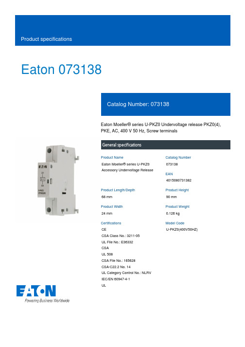
Eaton 073138Eaton Moeller® series U-PKZ0 Undervoltage release PKZ0(4),PKE, AC, 400 V 50 Hz, Screw terminalsGeneral specificationsEaton Moeller® series U-PKZ0Accessory Undervoltage Release073138401508073138268 mm90 mm24 mm0.126 kgCECSA Class No.: 3211-05UL File No.: E36332CSAUL 508CSA File No.: 165628CSA-C22.2 No. 14UL Category Control No.: NLRV IEC/EN 60947-4-1UL U-PKZ0(400V50HZ)Product Name Catalog NumberEANProduct Length/Depth Product Height Product Width Product Weight Certifications Model CodeScrew connection Can be fitted to left side of the motor protection switchAccessoriesEMERGENCY STOP or EMERGENCY switching-off device inaccordance with IEC/EN 60204 when combined with circuitbreakerMotor safety switchMotor protective circuit-breakerAC-25 °C 55 °C 1 x (0.75 - 2.5) mm²2 x (0.75 - 2.5) mm²1 x (18 - 14)2 x (18 - 14)42 V 480 V 24 V 250 V 0,7- 0,35 x Uc 0.85 - 1.1 V x Uc 400 V400 V0 VElectric connection type Mounting positionProduct categorySuitable asSuitable forUsed withVoltage typeAmbient operating temperature - minAmbient operating temperature - maxTerminal capacity (solid/flexible with ferrule)Terminal capacity (solid/stranded AWG)Rated operational voltage (Ue) at AC - min Rated operational voltage (Ue) at AC - max Rated operational voltage (Ue) at DC - min Rated operational voltage (Ue) at DC - max Drop-out voltagePick-up voltageRated control supply voltage (Us) at AC, 50 Hz - min Rated control supply voltage (Us) at AC, 50 Hz - max Rated control supply voltage (Us) at AC, 60 Hz - min Rated control supply voltage (Us) at AC, 60 Hz - max0 V0 V0 V5 VA, Pull-in power, Coil in a cold state and 1.0 x Us 5 VA, Pull-in power, Coil in a cold state and 1.0 x Us 3 VA, Coil in a cold state and 1.0 x Us3 VA, Coil in a cold state and 1.0 x Us 0 W0 W0 W0 A0.5 WMeets the product standard's requirements.Meets the product standard's requirements.Meets the product standard's requirements.Meets the product standard's requirements.Meets the product standard's requirements.Does not apply, since the entire switchgear needs to be evaluated.Does not apply, since the entire switchgear needs to be evaluated.Rated control supply voltage (Us) at DC - minRated control supply voltage (Us) at DC - maxNumber of contacts (change-over contacts)Number of contacts (normally closed contacts)Number of contacts (normally open contacts)Power consumption, pick-up, 50 Hz Power consumption, pick-up, 60 Hz Power consumption, sealing, 50 Hz Power consumption, sealing, 60 Hz Equipment heat dissipation, current-dependent PvidHeat dissipation capacity PdissHeat dissipation per pole, current-dependent PvidRated operational current for specified heat dissipation (In) Static heat dissipation, non-current-dependent Pvs10.2.2 Corrosion resistance10.2.3.1 Verification of thermal stability of enclosures10.2.3.2 Verification of resistance of insulating materials to normal heat10.2.3.3 Resist. of insul. mat. to abnormal heat/fire by internal elect. effects10.2.4 Resistance to ultra-violet (UV) radiation10.2.5 Lifting10.2.6 Mechanical impactMeets the product standard's requirements.Does not apply, since the entire switchgear needs to be evaluated.Meets the product standard's requirements.Does not apply, since the entire switchgear needs to be evaluated.Does not apply, since the entire switchgear needs to be evaluated.Is the panel builder's responsibility.Is the panel builder's responsibility.Is the panel builder's responsibility.Is the panel builder's responsibility.Is the panel builder's responsibility.The panel builder is responsible for the temperature rise calculation. Eaton will provide heat dissipation data for the devices.Is the panel builder's responsibility. The specifications for the switchgear must be observed.Is the panel builder's responsibility. The specifications for the switchgear must be observed.The device meets the requirements, provided the information in the instruction leaflet (IL) is observed.Motor Starters in System xStart - brochureSave time and space thanks to the new link module PKZM0-XDM32MEProduct Range Catalog Switching and protecting motorsSwitching and protecting motors - catalogDA-DC-00004232.pdfDA-DC-00004244.pdfDA-DC-00004246.pdfDA-DC-00004109.pdfDA-DC-00004545.pdfDA-DC-00004245.pdfDA-DC-00004601.pdfDA-DC-00004554.pdfDA-DC-00004067.pdfDA-DC-00004230.pdfDA-DC-00004069.pdfDA-DC-00003914.pdfDA-DC-00004206.pdfDA-DC-00004108.pdfDA-DC-00004915.pdfDA-DC-00004910.pdfDA-DC-00004951.pdfDA-DC-00004890.pdfDA-DC-00004787.pdfDA-DC-00004911.pdfDA-DC-00004935.pdfDA-DC-00004912.pdfDA-DC-00004886.pdfDA-DC-00004945.pdfDA-DC-00004913.pdfDA-DC-00004878.pdfDA-DC-00004883.pdfDA-DC-00004884.pdf10.2.7 Inscriptions10.3 Degree of protection of assemblies10.4 Clearances and creepage distances10.5 Protection against electric shock10.6 Incorporation of switching devices and components 10.7 Internal electrical circuits and connections10.8 Connections for external conductors10.9.2 Power-frequency electric strength10.9.3 Impulse withstand voltage10.9.4 Testing of enclosures made of insulating material 10.10 Temperature rise10.11 Short-circuit rating10.12 Electromagnetic compatibility10.13 Mechanical function BrochuresCataloguesCertification reports Declarations of conformityDA-DC-00004881.pdfDA-DC-00004921.pdfDA-DC-00004851.pdfDA-DC-00004920.pdfDA-DC-00004961.pdfDA-DC-00004882.pdfDA-DC-00004892.pdfDA-DC-00004880.pdfDA-DC-00004914.pdfDA-DC-00004962.pdfDA-DC-00004937.pdfDA-DC-00004944.pdfDA-DC-00004953.pdfDA-DC-00004891.pdfDA-DC-00004952.pdfDA-DC-00004960.pdfDA-DC-00004879.pdfDrawingseaton-manual-motor-starters-release-u-pkz0-accessory-dimensions.eps eaton-manual-motor-starters-release-u-pkz0-accessory-3d-drawing.eps eaton-manual-motor-starters-shunt-releases-u-pkz0-accessory-3d-drawing.epseCAD modelDA-CE-ETN.U-PKZ0(400V50HZ)Installation instructionsIL03402034ZInstallation videosWIN-WIN with push-in technologymCAD modelDA-CS-a_pkzDA-CD-a_pkzWiring diagramseaton-manual-motor-starters-undervoltage-u-pkz0-accessory-wiring-diagram.epsEaton Corporation plc Eaton House30 Pembroke Road Dublin 4, Ireland © 2023 Eaton. All rights reserved. Eaton is a registered trademark.All other trademarks areproperty of their respectiveowners./socialmedia。
苏州谐通光伏科技股份有限公司PV-XT101.1产品规格说明书
产品规格书Product Specification产品名称:PV-XT101.1Product Name:PV-XT101.1供应商名称:苏州谐通光伏科技股份有限公司Vendor name:Suzhou Xtong Photovoltaic Technologies Co.Ltd 版本Version:A/2Revision HistoryRev.Date Revised Item Revised Content Remark A02018.4.23N/A初版中英文曾磊A12018.7.18细节调整第六章英文翻译优化,页眉优化,目许琦彦录优化,节标题分级A22018.7.28英文版完善英文翻译完善,安装示意图更新许琦彦A32018.8.30完善安装说明机器安装说明曾磊目录1.产品外观及设计性能参数要求(PRODUCT APPEARANCE AND DESIGNED PERFORMANCE PARAMETERS) (5)2.连接器BOM清单(BOM OF CONNECTOR) (6)3.连接器图纸(DRAWING OF CONNECTOR) (7)4.安全说明(SAFETY INSTRUCTIONS) (9)5.手动安装过程(MANUALLY ASSEMBLING GUIDE) (11)5.1.工具要求(T OOLS REQUIRED) (11)(1)压线钳C ABLE C RIMPER (11)(2)剥线钳C ABLE S TRIPPER (11)(3)连接器扳手一对C ONNECTOR S PANNERS (12)5.2.线缆准备(C ABLE P REPARING) (12)(1)剥线C ABLE S TRIPPING (12)5.3.压接(C RIMPING) (12)(1)放置压线端子P LACING THE TERMINAL INTO THE CRIMPING POSITION (12)(2)固定压线端子F IXING THE TERMINAL (13)(3)线缆铆压P LACING THE CABLE AND CRIMPING (14)(4)铆压质量检查C HECKING THE CRIMPING QUALITY (14)5.4.安装连接器(C ONNECTOR BODY ASSEMBLING) (14)(1)插入端子I NSERTING THE TERMINAL (14)(2)螺母拧紧T IGHTENING THE NUTS (15)5.5.PV-XT101.1连接器插拔方式(P LUGGING AND UNPLUGGING THE PV-XT101.1) (16)(1)连接器插入(P LUGGING THE CONNECTORS) (16)(2)连接器拔出(U NPLUGGING THE CONNECTORS) (16)(3)线缆扭转(C ABLE ROUTING) (16)6.机器安装过程(MACHINE ASSEMBLY PROCESS) (17)6.1.剥线(C ABLE S TRIPPING) (17)6.2.刀头(B IT TOOL) (17)6.3.安装连接器(C ONNECTOR BODY ASSEMBLING) (18)(1)插入端子I NSERTING THE TERMINAL (18)(2)螺母拧紧T IGHTENING THE NUTS (18)7.附录(APPENDIX) (19)7.1.耐化学品附表(C OMPATIBILITY WITH CHEMICALS) (19)7.2.外箱标签命名方式: (19)7.3.连接器责任免除条款(E XCLUSION T ERMS) (22)1.产品外观及设计性能参数要求(Product appearance and designedperformance parameters)额定电压Rated Voltage:TUV1500V/UL1500V额定电流Rated Current:35A(4mm²/12AWG)接触电阻Contact Resistance:≤0.5mΩ环境温度Temperature Range:-40℃∽+85℃IP等级Protection Degree:IP68安全等级Protection Class:Ⅱ防火等级Flammability Class:UL94V-02.连接器BOM清单(BOM of connector)产品名称Product name 连接器connector版本VersionA0产品型号Type Name PV-XT101.1张数Pages1客户Customer 发行日期Issue date2017.05.25序号Item 名称Name材质Material生产厂商Manufacturer数量Quantity备注Remark1正极FemaleMPEE/1pcs2负极MaleMPPE/1pcs3螺母NutPA66/2pcs4花篮GripMPPE/2pcs5T型圈T ring硅橡胶silica gel/2pcs6O型圈O ring硅橡胶silica gel/1pcs7插针Minusterminal铜镀锡Copper,tin plated/1pcs8插套Plus terminal铜镀锡Copper,tin plated/1pcs9止退圈Check ring不锈钢stainless steel/1pcs3.连接器图纸(Drawing of connector)4.安全说明(Safety Instructions)(1)该产品应由经过专家培训的、具有相关安全应用规范的专业人员安装。
- 1、下载文档前请自行甄别文档内容的完整性,平台不提供额外的编辑、内容补充、找答案等附加服务。
- 2、"仅部分预览"的文档,不可在线预览部分如存在完整性等问题,可反馈申请退款(可完整预览的文档不适用该条件!)。
- 3、如文档侵犯您的权益,请联系客服反馈,我们会尽快为您处理(人工客服工作时间:9:00-18:30)。
ZG
Performance Characteristics
– 40 ~ +105°C 6.3 ~ 50V 0.1 ~ 100µF ± 20% at 120Hz, 20°C After 2 minutes' application of rated voltage, leakage current is not more than 0.01CV or 3 (µA) , whichever is greater.
Frequency Coefficient 50 Hz 0.70 120 Hz 1.00 300 Hz 1.17 1 kHz 1.36 10 kHz~ 1.50
Taping specifications are given in page 24. Recommended land size, soldering by reflow are given in page 25, 26. Please select UX(p.74), UJ(p.76) series if high C/V products are reqired. Please refer to page 3 for the minimum order quantity.
Voltage mark for 6.3V is 6V .
0.5 ~ 0.8
Negative
Dimensions
V Cap. (µF) Code
6.3 0J
10 1A
A±0.2 A + 0.2 –
X2P 10 16V
φD±0.5
B±0.2
E
16 1C
25 1E
35 1V 4 4 4 4 4 4 4 5 6.3
WT
Smaller
ZT
Smaller
Specifications
Item Category Temperature Range Rated Voltage Range Rated Capacitance Range Capacitance Tolerance Leakage Current tan δ
Chip Type
105°C Marking Capacitance Lot No. Plastic platform Voltage 0.3 MAX.
0.5 MAX.
C±0.2
Type numbering system (Example : 16V 10µF)
Positive
1
2
3
4
5
6
7
8
9 10
35 0.14 25 3 6 35 3 4
50 0.1uency : 120Hz
Stability at Low Temperature
Rated voltage (V) Z– 25°C / Z+20°C Impedance ratio Z– 40°C / Z+20°C ZT / Z20 (MAX.)
50 1H 0.9 2.2 2.8 3.3 5.4 9.6 12 16 26
0.1 0.22 0.33 0.47 1 2.2 3.3 4.7 10 22 33 47 100
0R1 R22 R33 R47 010 2R2 3R3 4R7 100 220 330 470 101
4 5 5 6.3
19 26 32 52
Endurance
After 1000 hours' application of rated voltage at 105°C, capacitors meet the characteristic requirements listed at right.
Within ±25% of initial value (16V or less) Within ±20% of initial value (25V or more) tan δ 300% or less of initial specified value Leakage current Initial specified value or less
Measurement frequency : 120Hz, Temperature : 20°C Rated voltage (V) tan δ (MAX.)
6.3 0.38
10 0.32 6.3 6 10
16 0.20 10 5 10
Capacitance change
25 0.16 16 3 6
元器件交易网
ALUMINUM ELECTROLYTIC CAPACITORS
ZT
4.5mmL Chip Type, Wide Temperature Range
series
Chip type with 4.5mm height, operating over wide temperature range of – 40 ~ +105°C. Designed for surface mounting on high density PC board. Applicable to automatic mounting machine using carrier tape. Adapted to the RoHS directive (2002/95/EC).
5 5 6.3
24 30 40
4 5 6.3 6.3
16 26 35 44
4 5 6.3 6.3
11 20 33 42
4 5 6.3
13 22 36
Case size φ D (mm)
Rated ripple
Rated Ripple (mArms) at 105°C 120Hz
Frequency coefficient of rated ripple current
Shelf Life Resistance to soldering heat Marking
After storing the capacitors under no load at 105°C for 1000 hours, and after performing voltage treatment based on JIS C 5101-4 clause 4.1 at 20°C, they will meet the specified value for endurance characteristics listed above. The capacitors shall be kept on the hot plate maintained at 250°C Capacitance change Within ±10% of initial value for 30 seconds. After removing from the hot plate and restored tan δ Initial specified value or less at room temperature, they meet the characteristic requirements Initial specified value or less Leakage current listed at right. Black print on the case top.
CAT.8100V
11 12 13 14
U Z T 1 C 1 0 0 MC L 1 GB
Taping code
φD
4.5
+0.1 –0.2
A B C E
4 1.8 4.3 4.3 1.0
(mm) 5 6.3 2.1 2.4 5.3 6.6 5.3 6.6 1.3 2.2
Configuration Capacitance tolerance (±20%) Rated Capacitance (10µF) Rated voltage (16V) Series name Type
