DSS-301MC22R中文资料
RE22R2AMR产品数据手册说明书

RE22R2AMR.T h e i n f o r m a t i o n p r o v i d e d i n t h i s d o c u m e n t a t i o n c o n t a i n s g e n e r a l d e s c r i p t i o n s a n d /o r t e c h n i c a l c h a r a c t e r i s t i c s o f t h e p e r f o r m a n c e o f t h e p r o d u c t s c o n t a i n e d h e r e i n .T h i s d o c u m e n t a t i o n i s n o t i n t e n d e d a s a s u b s t i t u t e f o r a n d i s n o t t o b e u s e d f o r d e t e r m i n i n g s u i t a b i l i t y o r r e l i a b i l i t y o f t h e s e p r o d u c t s f o r s p e c i f i c u s e r a p p l i c a t i o n s .I t i s t h e d u t y o f a n y s u c h u s e r o r i n t e g r a t o r t o p e r f o r m t h e a p p r o p r i a t e a n d c o m p l e t e r i s k a n a l y s i s , e v a l u a t i o n a n d t e s t i n g o f t h e p r o d u c t s w i t h r e s p e c t t o t h e r e l e v a n t s p e c i f i c a p p l i c a t i o n o r u s e t h e r e o f .N e i t h e r S c h n e i d e r E l e c t r i c I n d u s t r i e s S A S n o r a n y o f i t s a f f i l i a t e s o r s u b s i d i a r i e s s h a l l b e r e s p o n s i b l e o r l i a b l e f o r m i s u s e o f t h e i n f o r m a t i o n c o n t a i n e d h e r e i n .Product data sheetCharacteristicsRE22R2AMROn-delay Timing Relay - 0.05s…300h - 24…240V AC/DC - 2C/OMainRange of product Zelio TimeProduct or component typeModular timing relay Discrete output type Relay Device short name RE22Nominal output current8 AComplementaryContacts type and composition 1 C/O timed or instantaneous contact, cadmium free 1 C/O timed contact, cadmium free Time delay type A AwTime delay range0.3...3 s 1...10 s 0.05...1 s 3...30 s 10...100 s 30...300 s 3...30 min 30...300 min 3...30 h 30...300 hControl typeExternal potentiometer Diagnostic button Rotary knob[Us] rated supply voltage 24...240 V AC/DC at 50/60 Hz Release input voltage <= 2.4 V Voltage range 0.85...1.1 Us Supply frequency 50...60 Hz (+/- 5 %)Connections - terminalsScrew terminals : 2 x 0.2...2 x 1.5 mm², AWG 24...AWG 16 flexible cable with ca-ble endScrew terminals : 1 x 0.2...1 x 2.5 mm², AWG 24...AWG 14 flexible cable with ca-ble endScrew terminals : 2 x 0.5...2 x 2.5 mm², AWG 20...AWG 14 solid cable without cable endScrew terminals : 1 x 0.5...1 x 3.3 mm², AWG 20...AWG 12 solid cable without cable endTightening torque 0.6...1 N.m conforming to IEC 60947-1Housing material Self-extinguishingRepeat accuracy +/- 0.5 % conforming to IEC 61812-1Temperature drift +/- 0.05 %/°C Voltage drift+/- 0.2 %/VSetting accuracy of time delay +/- 10 % of full scale at 25 °C conforming to IEC 61812-1Control signal pulse width 30 ms100 ms (with load in parallel)Insulation resistance 100 MOhm at 500 V DC conforming to IEC 60664-1Recovery time120 ms (on de-energisation)Immunity to microbreaks <= 10 ms Power consumption in VA3 VA at 240 V ACPower consumption in W 1.5 W at 240 V DCSwitching capacity in VA2000 VAMinimum switching current10 mA 5 V DCMaximum switching current8 AMaximum switching voltage250 V ACElectrical durability100000 cycles for 2 A at 24 V DC-1100000 cycles for 8 A at 250 V AC-1Mechanical durability10000000 cyclesRated impulse withstand voltage 5 kV for 1.2...50 µs conforming to IEC 60664-1Power on delay< 100 msCreepage distance 4 kV/3 conforming to IEC 60664-1Overvoltage category III conforming to IEC 60664-1Mounting position Any positionMounting support35 mm DIN rail conforming to EN/IEC 60715Status LED Yellow LED (slow flashing) for timing in progress and output relay energisedYellow LED (fast flashing) for timing in progress and output relay de-energisedYellow LED (steady) for output relay energisedGreen LED backlight (steady) for dial pointer indicationProduct weight0.105 kgEnvironmentDielectric strength 2.5 kV for 1 mA/1 minute at 50 Hz between relay output and power supply withbasic insulation conforming to IEC 61812-1Standards IEC 61812-1UL 508Directives2004/108/EC - electromagnetic compatibility2006/95/EC - low voltage directiveProduct certifications CCCCECSAGLULRCMEACChina RoHSAmbient air temperature for operation-20...60 °CAmbient air temperature for storage-40...70 °CIP degree of protection IP50 (front panel) conforming to IEC 60529IP20 (terminals) conforming to IEC 60529IP40 (housing) conforming to IEC 60529Pollution degree 3 conforming to IEC 60664-1Vibration resistance20 m/s² (f = 10...150 Hz) conforming to IEC 60068-2-6Shock resistance 5 gn (in operation) (duration = 11 ms) conforming to IEC 60068-2-2715 gn (not operating) (duration = 11 ms) conforming to IEC 60068-2-27 Relative humidity95 % at 25...55 °CElectromagnetic compatibility Immunity to microbreaks and voltage drops (test level: 100 % - 20 ms) conform-ing to IEC 61000-4-11Immunity to microbreaks and voltage drops (test level: 30 % - 500 ms) conform-ing to IEC 61000-4-11Fast transient bursts (test level: 2 kV, level 3 - direct contact) conforming to IEC61000-4-4Conducted RF disturbances (test level: 10 V, level 3 - 0.15...80 MHz) conformingto IEC 61000-4-6Radiated radio-frequency electromagnetic field immunity test (test level: 10 V/m,level 3 - 80 MHz...1 GHz) conforming to IEC 61000-4-3Electrostatic discharge (test level: 8 kV, level 3 - air discharge) conforming to IEC61000-4-2Electrostatic discharge (test level: 6 kV, level 3 - contact discharge) conforming toIEC 61000-4-2Surge immunity test (test level: 2 kV, level 3 - common mode) conforming to IEC61000-4-5Surge immunity test (test level: 1 kV, level 3 - differential mode) conforming toIEC 61000-4-5Fast transients immunity test (test level: 1 kV, level 3 - capacitive connecting clip)conforming to IEC 61000-4-4Product data sheetRE22R2AMR Dimensions DrawingsDimensionsProduct data sheetRE22R2AMR Connections and SchemaWiring DiagramProduct data sheetRE22R2AMRTechnical DescriptionFunction A: Power On-DelayDescriptionOn energisation of power supply, the timing period T starts. After timing, the output(s) R close(s).The second output (R2) can be either timed (when set to "TIMED") or instantaneous (when set to "INST").Function: 1 OutputFunction: 2 OutputsFunction Aw : Power On-Delay With Retrigger / Restart ControlDescriptionOn energisation of power supply, the timing period T starts.At the end of the timing period T, the output(s) R close(s).Energization of Y1 makes the output(s) R open(s).Deenergization of Y1 restarts timing period T.At the end of timing period T, the output(s) R close(s).The second output (R2) can be either timed (when set to "TIMED") or instantaneous (when set to "INST")Function: 1 OutputFunction: 2 OutputsLegendRelay de-energisedRelay energisedOutput openOutput closedUSupply-TTiming period-R1/2 timed outputsR2-R2The second output is instantaneous if the right position is selected inst.-Retrigger / Restart controlY1-RE22R2AMR.。
DSS系统使用手册(中文版)最详细

数字媒体发布系统使用手册目录DSS系统名词解释...................................................................................................................................... - 3 -一.软件的安装......................................................................................................................................... - 5 -二.视频播出功能软件和插件的安装....................................................................................................... - 8 -2.1M ICROSOFT M EDIA P LAYER 10插件的安装(必须W INDOW XP及以上版本) (8)2.2M ICROSOFT P OWER P OINT VIEWER 97插件的安装 (9)2.3A DOBE FLASH PLAYER 9A CTIVE X插件的安装 (10)2.4 FFDSHOW插件的安装 (10)2.6Q UICK T IME A LTERNATIVE插件的安装 (11)2.7R EAL A LTERNATIVE插件的安装 (11)三.MICROSOFT补丁包的安装 ............................................................................................................... - 12 -3.1M ICROSOFT D IRECT X插件的安装: (12)3.2M F RAMEWORK 1.1安装步骤 (13)四.DSS 2.5版本系统软件的设置 ........................................................................................................... - 13 -4.1DSS2.5版本系统软件介绍 (13)4.1.1 DSS Editor的介绍.................................................................................................................... - 13 -4.1.2 DSS Server Daemon的介绍 ...................................................................................................... - 14 -4.1.3 DSS Network Manager的介绍 .................................................................................................. - 14 -4.2DSS系统软件的设置 (14)4.2.1设置DSS Server Daemon........................................................................................................... - 14 -4.2.2设置DSS Editor......................................................................................................................... - 15 -4.2.3设置DSS Network Manager ....................................................................................................... - 18 -五.应用软件使用说明 ........................................................................................................................... - 20 -5.1DSS E DITOR的使用说明 (20)5.1.1 文本制作单元............................................................................................................................. - 22 -5.1.2 RSS导入单元.............................................................................................................................. - 25 -5.1.3 Alpha和Alpha序列导入单元(透明图片及透明序列) ...................................................... - 26 -5.1.4 网页导入单元............................................................................................................................. - 27 -5.1.5 视频,音频导入单元................................................................................................................... - 27 -5.1.6 图片导入单元............................................................................................................................. - 28 -5.1.7 数据导入单元............................................................................................................................. - 29 -5.1.8 流媒体导入单元......................................................................................................................... - 30 -5.1.9 复合区域导入单元..................................................................................................................... - 31 -5.1.10 FTP更新目录导入单元............................................................................................................ - 32 -5.1.11设置播放顺序............................................................................................................................ - 33 -5.1.14添加页面序列............................................................................................................................ - 34 -5.1.15 发布项目................................................................................................................................... - 35 -5.2DSS N ETWORK M ANAGER的使用说明 (36)5.2.1界面说明...................................................................................................................................... - 36 -5.2.2针对整个网络的操作.................................................................................................................. - 37 -5.2.3编辑播放器/播放器组................................................................................................................ - 38 -5.2.4查看和编辑播放器及播放器组的信息 ...................................................................................... - 39 -5.2.5右侧状态信息界面的说明及操作 .............................................................................................. - 40 -5.2.6针对播放器组的操作(图5-52) ............................................................................................. - 43 -5.2.7课表管理的使用.......................................................................................................................... - 44 -5.2.8服务信息的查看.......................................................................................................................... - 48 -5.2.9节目管理的使用.......................................................................................................................... - 49 -5.2.10 DataFlow功能的使用.............................................................................................................. - 50 -六.播放器的使用(WS-20HD) .................................................................................................................. - 51 -6.1播放器配置 (51)6.2注意事项 (55)6.3故障处理 (56)七.软件注册........................................................................................................................................... - 57 -7.1DSS E DITOR(编辑制作端)注册流程 (57)7.2DSS N ETWORK M ANGER注册流程 (58)7.3DSS S ERVER D AEMON注册过程 (60)7.4DSS P LAYER注册过程 (60)7.4.1单个DSS Player注册(一) .................................................................................................... - 60 -7.4.2单个DSS Player注册(二) .................................................................................................... - 62 -7.4.3多个DSS player和DSS Server Daemon批量注册 ................................................................ - 63 -八.应用实例- 编辑发布和播放一个节目.............................................................................................. - 64 -8.1启动Q OVISION S ERVER D AEMON (64)8.2制作节目 (65)8.3管理和指派节目 (73)九.扩展功能介绍 ................................................................................................................................... - 76 -9.1D ATAFLOW功能说明 (76)9.2连接LED显示屏 (79)9.3连接医院/银行排队叫号系统 (80)十.DSS 售后服务......................................................................................................... 错误!未定义书签。
DSS综合监控管理平台一体机初始配置手册V

综合监控管理平台一体机初始配置手册浙江大华科技有限公司法律声明版权声明? 2014 浙江大华科技有限公司。
版权所有。
在未经浙江大华科技有限公司(下称“大华”)事先书面许可的情况下,任何人不能以任何形式复制、传递、分发或存储本文档中的任何内容。
本文档描述的产品中,可能包含大华及可能存在的第三人享有版权的软件。
除非获得相关权利人的许可,否则,任何人不能以任何形式对前述软件进行复制、分发、修改、摘录、反编译、反汇编、解密、反向工程、出租、转让、分许可等侵犯软件版权的行为。
商标声明、、、、是浙江大华技术股份有限公司的商标或注册商标。
在本文档中可能提及的其他商标或公司的名称,由其各自所有者拥有。
更新与修改为增强本产品的安全性、以及为您提供更好的用户体验,大华可能会通过软件自动更新方式对本产品进行改进,但大华无需提前通知且不承担任何责任。
大华保留随时修改本文档中任何信息的权利,修改的内容将会在本文档的新版本中加入,恕不另行通知。
产品部分功能在更新前后可能存在细微差异。
前言概述本文档详细描述了DSS7000综合监控管理平台的配置和使用。
符号约定在本文中可能出现下列标志,它们所代表的含义如下:防静电电击防护激光辐射目录1开箱检查1.1检查步骤当您接收到设备时,请参考以下步骤进行检查。
步骤1检查产品外包装箱外观有无明显的损坏。
步骤2打开产品外包装箱,检查产品随机配备的附件是否齐全。
步骤3检查无误后,可除去设备上的保护膜。
1.2前面板说明DSS7000系列前面板如错误!未找到引用源。
错误!未找到引用源。
和所示。
图1-1前面板1(7016)图1-2前面板2(7024)卸下前面罩后,将看到硬盘如错误!未找到引用源。
和错误!未找到引用源。
所示。
第一块硬盘区插系统盘。
硬盘架上有两个指示灯,上方为电源指示灯,黄色代表接通电源,下方为读写操作灯,蓝色闪烁代表有数据读写。
图1-3前面板3(7016含16个槽位)图1-4前面板4(7024含24个槽位)1.3后面板接口说明DSS7000系列后面板如错误!未找到引用源。
DSS端口开放说明文档-V1.0

答复:从这个需求可以看出,总共需要端口数:(16*2+16)*4=192个。考虑到:cms释放资源需要1、2秒,所以推荐开放256个端口。
c:\program files\DSS\CMS\cms.xml (根据实际安装路径,可能位置不
大华综合监控管理平台一体机管理端操作手册v130浙江大华科技有限公司前言概述本文档详细描述了dss7000系列管理端的菜单界面设备管理用户管理日常
DSS端口开放说明文档-V1.0
软件产品线解决方案组
修订记录
9200Байду номын сангаасdms监听端口
9320:ss监听端口
9400:pes监听端口(dss-f专有)
9500:ars监听端口(有代理设备时需要开放)
DSS20-01AC中文资料
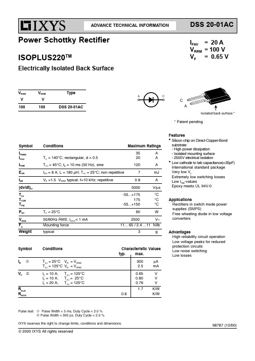
11... 65 / 2.4 ...11 N/lb Advantages High reliability circuit operation Low voltage peaks for reduced protection circuits Low noise switching Low losses
TC = 25°C 50/60Hz RMS; IISOL< 1 mA Mounting force typical
90 2500 3
Applications Rectifiers in switch mode power supplies (SMPS) Free wheeling diode in low voltage converters
98787 (12/00)
© 2000 IXYS All rights reserved
元器件交易网
DSS 20-01AC
ISOPLUS220 OUTLINE
Note: All terminals are solder plated. 1 - Cathode 3 - Anode
元器件交易网
ADVANCE TECHNICAL INFORMATION
DSS 20-01AC
IFAV = 20 A VRRM = 100 V VF = 0.65 V
Power Schottky Rectifier ISOPLUS220TM
Electrically Isolated Back Surface
Symbol IR Q VFR
Conditions TVJ = 25°C VR = VRRM TVJ = 125°C VR = VRRM IF = 10 A; IF = 10 A; IF = 20 A; TVJ = 125°C TVJ = 25°C TVJ = 125°C
SRB 301MC-24V商品说明书
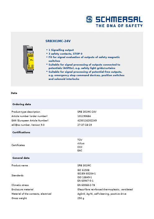
DataOrdering data Product type description SRB 301MC-24V Article number (order number)101190684EAN (European Article Number)4250116202249eCl@ss number, Version 9.027-37-18-19CertificationsCertificatesTÜVcULus CCC EACGeneral data Product nameSRB 301MC StandardsIEC 61508IEC/EN 60204-1 ISO 13849-1 EN 60947-5-1Climatic stress EN 60068-2-78Enclosure materialGlass-fibre reinforced thermoplastic, ventilated Material of the contacts, electrical AgSn0, Ag-Ni, self-cleaning, positive drive Gross weight250 gSRB301MC-24V1 Signalling output 3 safety contacts, STOP 0Fit for signal evaluation of outputs of safety magnetic switchesSuitable for signal processing of outputs connected to potentials (AOPDs), e.g. safety light grids/curtains Suitable for signal processing of potential-free outputs, e.g. emergency stop command devices, position switches and solenoid interlocksGeneral data - FeaturesStop-Category0 Electronic Fuse Yes Wire breakage detection Yes Short-circuit recognition Yes Start input Yes Feedback circuit Yes Automatic reset function Yes Earth connection detection Yes Integral System Diagnostics, status Yes Number of auxiliary contacts1 Number of LEDs4 Number of openers2 Number of safety contacts3Safety appraisalStandards EN 60947-5-1 IEC 61508Safety appraisal - Relay outputsPerformance Level, Stop 0eCategory, Stop 04Diagnostic Coverage (DC) Level, Stop 0≥ 99 %PFH-Value Stop 0 2.00 x 10⁻⁸ /hSafety Integrity Level (SIL), Stop 03Mechanical dataMounting Snaps onto standard DIN rail to EN 60715 Mechanical life, minimum10,000,000 OperationsMechanical data - Connection techniqueTerminal Connector Screw connection rigid or flexibleTerminal designations IEC/EN 60947-1 Cable section, minimum0.25 mm²Cable section, maximum 2.5 mm²Tightening torque of Clips0.6 NmMechanical data - DimensionsWidth22.5 mmHeight100 mmDepth121 mmAmbient conditionsProtection class of the enclosure IP40Protection class of the Clearance IP54Protection class of Clips or Terminals IP20Ambient temperature, minimum-25 °CAmbient temperature, maximum+60 °CStorage and transport temperature, minimum-40 °CStorage and transport temperature, maximum+85 °CResistance to vibrations to EN 60068-2-610...55 Hz, Amplitude 0.35 mm, ± 15 % Restistance to shock30 g / 11 msAmbient conditions - Insulation valueRated impulse withstand voltage 4 kVIIIDegree of pollution to IEC/EN 60664-12Electrical dataFrequency range 50 Hz 60 HzRated operating voltage 24 VAC -15% / +10%24 VDC -15%/+20%, residual ripple max. 10%Rated AC voltage for controls, 50 Hz, minimum20.4 VAC Rated control voltage at AC 50 Hz, maximum26.4 VAC Rated AC voltage for controls, 60 Hz, minimum20.4 VAC Rated control voltage at AC 60 Hz, maximum26.4 VAC Rated AC voltage for controls at DC minimum20.4 VDC Rated control voltage at DC, maximum28.8 VDC Electrical power consumption 2 W Electrical power consumption 4.9 VA Contact resistance, maximum0.1 ΩNote (Contact resistance)in new state Drop-out delay in case of power failure, typically80 msDrop-out delay in case of emergency, typically20 msPull-in delay at automatic start, maximum, typically100 msPull-in delay at RESET, typically20 ms Electrical data - Safe relay outputsSwitching capacity, minimum10 VDC Switching capacity, minimum10 mASwitching capacity, maximum 250 VAC Switching capacity, maximum 8 AElectrical data - Digital inputs Conduction resistance, maximum40 ΩElectrical data - Relay outputs (auxiliary contacts)Switching capacity, maximum 24 VDC Switching capacity, maximum2 AElectrical data - Electromagnetic compatibility (EMC)EMC-DirectiveStatus indicationIndicated operating statesPosition relay K2Position relay K1Internal operating voltage U<sub>i</sub>Other dataNote (applications)Safety sensor Guard systemEmergency-Stop buttonPull-wire emergency stop switches Safety light curtainPicturesProduct picture (catalogue individual photo)ID: ksrb3f20| 89,3 kB | .png | 74.083 x 147.461 mm - 210 x 418 Pixel - 72 dpi| 743,3 kB | .jpg | 265.642 x 529.167 mm - 753 x 1500 Pixel - 72 dpi| 154,4 kB | .jpg | 27.093 x 53.933 mm - 320 x 637 Pixel - 300 dpiWiring example| 112,8 kB | .jpg | 352.778 x 226.483 mm - 1000 x 642Pixel - 72 dpiSymbol (technical standard)| 191,1 kB | .jpg | 352.778 x 246.592 mm - 1000 x 699Pixel - 72 dpiK.A. Schmersal GmbH & Co. KG, Möddinghofe 3, D-42279 WuppertalThe details and data referred to have been carefully checked. Images may diverge from original. Further technical data can be found in the manual. Technical amendments and errors possible.Generated on 08.07.2020 17:17:04。
Z-15EW22R中文资料(omron)中文数据手册「EasyDatasheet - 矽搜」
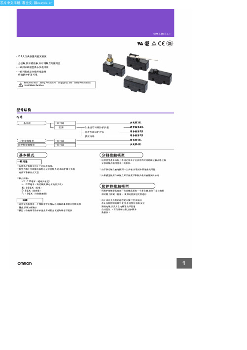
Z-@55-M@@@M
(1) (2)(3) (4)
( 1)防滴型 ( 2)铅奥特莱斯
01 15 H2 H G E None S D K K3 Q3 Q Q8 Q22 Q21 L L2 W21 W W3 W32 W4 W44 W78 W52 W22 W2 W25 W49 W54 W2277 M M22 M2 NJ NJS None 55 A55
H (0.25 mm) Model
Z-15H Z-15H-B Z-15HS Z-15HS-B Z-15HD Z-15HD-B
H2 (0.20 mm) Model
Z-15H2 Z-15H2-B
E (1.8 mm) Model
Z-15E Z-15E-B
H (0.25 mm) Model
Z-01H Z-01H-B Z-01HS Z-01HS-B Z-01HD Z-01HD-B
( 5)终端
: 15 A
:0.20(超高灵敏度) 0.25毫米(高感光度, 微负载) :0.5毫米(标准) 1.8毫米(高容量)
( 2)触点间隙
None 19
: VSF : VCT L型 D型 R型
( 3)四通八达 奥特莱斯(见下 图 .)
( 3)执行器
: : : : : : : : : : : : : : : : : : : : : : : : : : : : : : :
--------------------Z-01HW2255 Z-01HW2255-B
面板安装柱塞 面板安装滚轮 柱塞 面板安装交叉 滚轮柱塞 钢板弹簧 辊钢板弹簧 短铰链杆 长铰链杆 铰链杆 短铰链滚轮摇臂
--Z-15GQA55-B5V
--Z-15GQ22A55-B5V
DSS-201LS22B中文资料

M
DC Spark-over voltage tolerance
M 20 A S
A
Taping form
22
Taping dimensions
R
Packing form
Axial taping No taping
Code 12 22 00
Taping width 26 52 No taping
Pitch 10 10
14
元器件交易网
DSSV Series
SURGE ABSORBER
■Features
UL1459 FAX CSA-22.2 No.225-M90 ●Protects telephone line equipment (telephone, modem, facsimile etc.) against surge and overvoltage (UL1459, CSA-22.2 No. 225-M90).
B F R
Bulk pack Flat pack taping Reel taping
Marking
Color code Black Brown Red Orange Yellow Green Blue Purple Gray White
First color band Part number
Second color band The unit digit of lot number
UL 497A 3
FCC 1 FCC cycle 1)
DSSV-201M-YD
1 FCC10/560 sec. 100A ±3times, 10/160 sec. 200A ±3times 2 DOC 1cycle 10/1000 sec. 1KV-12times, 100/1000 sec. 1KV-12times respectively. 3 UL Standard UL 497A File No. E131010 N
DCS+WCDMA技术规格书(C)

MRRU-31D22型数字射频拉远系统技术规格书1用途MRRU-31D22型数字射频拉远系统是集DCS和WCDMA两种制式的一个系统,该系统是直接耦合基站信号,采用数字传输方式,将信号传输至远端进行覆盖的无线网络解决方案。
由MRRU-31D22A,以下分别简称为DAU和MRRU-31D22R,以下简称“DRU”组成。
下行信号从移动通信基站直接耦合到近端,经过下变频模块后变成中频信号,数字中频部分把中频信号经A/D变换器变换为数字信号,通过基带信号处理单元将其打包成适合标准协议(如CPRI)要求的帧格式后,由数字光纤收发器、数字光纤将其传送至远端;远端通过数字光纤收发器将基带数字信号送入基带信号处理单元,将其恢复成基带数据,经D/A变换器变成模拟中频信号,由上变频模块变换为射频信号后,通过功放放大后,经用户天线发射至覆盖区域,达到数字射频拉远覆盖的目的。
来自手机用户的信号,由远端用户天线以及分集天线接收后,按照与上述过程相反的流程传送回移动通信基站。
该产品是基于采用数字中频技术的光纤传输,克服模拟光纤传输时信号的信噪比恶化的缺点,具有大动态、低噪声的优点,并且在数字中频的基础上开发多种功能,比如混合组网、底噪关断、切换功能、自动载波跟踪、以太网接口、远程下载以及时延校准等,同时具有多种备份功能,如光旁路功能,以提高产品可靠性。
2功能1)系统由数字接入控制单元(DAU)和数字射频拉远单元(DRU)组成,采用两个独立的DAU分别接入系统;2)系统须支持WCDMA,DCS两种制式的射频数字拉远,同时支持WLAN的基带传输;3)整机支持外接蓄电池备份电源;4)DCS系统最大输出功率60W,WCDMA系统最大输出功率各40W;5)DCS上下行均采用载波选频,最多支持16个载波,WCDMA上下行均采用载波选频,最多支持3个载波;6)系统由DAU和DRU组成,可采用星型、菊花链以及混合组网方式;7)利用光纤传输,DCS与WCDMA传输距离最远可达18km,信号在光纤传输时无损耗,没有收发天线隔离问题,用户天线架设灵活,根据覆盖区域可选择定向或全向覆盖天线;8)上行具有底噪关断功能,在一拖多的应用形式下可保持较低的上行噪声;9)DCS、WCDMA均具备自动载波跟踪功能,使用维护方便;10)具备自动和手动时延校准,有效防止链型结构覆盖的同频干扰;11)具备升级软件远程下载功能;12)具备自愈功能, 在软、硬件出现故障时能自行恢复;13)DCS具备无线信道占用率统计功能,可推算话务量,有助于更好的进行网络优化;14)支持光旁路功能;15)采用满足CPRI标准的HDLC进行远程监控通信,性能稳定;16)本地监控功能(OMT):通过便携电脑对DAU或DRU进行增益设置及设备状态和工作参数查询,以及监控软件的更新下载,并且可以对主机和数字板分别进行复位设置。
MMDT2227_diodes
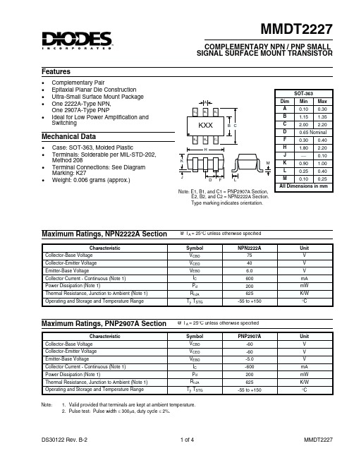
1. Valid provided that terminals are kept at ambient temperature. 2. Pulse test: Pulse width £ 300ms, duty cycle £ 2%.
DS30122 Rev. B-2
1 of 4
MMDT2227
Electrical Characteristics, NPN2222A Section
DC Current Gain
hFE
¾
Collector-Emitter Saturation Voltage Base- Emitter Saturation Voltage SMALL SIGNAL CHARACTERISTICS Output Capacitance Input Capacitance Current Gain-Bandwidth Product SWITCHING CHARACTERISTICS Turn-On Time Delay Time Rise Time Note:
Cobo Cibo fT
¾ — 200
pF pF MHz
ton td tr
¾ ¾ ¾
45 10 40
ns ns ns
1. Valid provided that terminals are kept at ambient temperature. 2. Pulse test: Pulse width £ 300ms, duty cycle £ 2%.
@ TA = 25°C unless otherwise specified Min -60 -60 -5.0 ¾ ¾ ¾ 75 100 100 100 50 ¾ ¾ Max ¾ ¾ ¾ -10 -50 -50 ¾ ¾ ¾ 300 ¾ -0.4 -1.6 -1.3 -2.6 8.0 30 ¾ Unit V V V nA mA nA nA Test Condition IC = -10mA, IE = 0 IC = -10mA, IB = 0 IE = -10mA, IC = 0 VCB = -50V, IE = 0 VCB = -50V, IE = 0, TA = 125°C VCE = -30V, VEB(OFF) = -0.5V VCE = -30V, VEB(OFF) = -0.5V IC = -100µA, VCE = IC = -1.0mA, VCE = IC = -10mA, VCE = IC = -150mA, VCE = IC = -500mA, VCE = -10V -10V -10V -10V -10V
薄芝糖肽注射液治疗皮肤病301例应用价值分析

!"#$#%&" ’()*+ ,$ -&,./# 0"+%,121(#*2 3$42%(#,$ 562&(#$7 8,%&" ’%"26,*269& :+ 8,%&" 3$42%(#,$
6789 :-; . <;=, >? :-@A< . B-;
( C-=ADED FDG=H@0 ?AEI=I;I=JA @AG C-=ADED KA=JA FDG=H@0 KA=LDME=IN, O@D/@IJ0J<N OJEP=I@0, Q=@AR=A (%%%!%)
停药、 服抗组织胺剂 停药后 71 停药后 &1 *0&<
薄芝糖肽注射液治疗常见皮肤病疗效观察
总 例数 // +’ -’ +* -+ -* # 痊愈 例数 ’/ )/ ’ ’# / * + 5 -)0 / +’6 " #0 #&0 * ’-0 & * ##0 7 &# ’* )# )+ ’’ ’* ’ 好转 例数 5 #-0 # +76 # &*0 * -&0 * #+0 7 ##0 7 --0 + + )+ * + )* * 无效 例数 5 +6 # "6 & +-0 7 * ))0 / --0 * 总有效 率 例数 /+ -/ )/ +* -* ’* # 5 "&6+ "*6& � )**0 * //0 ’ ##0 7 )**0 * 复发率 例数 / )’ * )* ’ * * 5 ’/6 # ##6 7 * -/0 & ’&0 * * *
(完整版)HCS301中文文档
HCS301 DATASHEET 中文版翻译:Nforever of WEE 1.产品特点:1.1安全性●28位可编程序列号●64位可编程加密密钥●每次发射都是唯一的●发射码长度为66位●32位滚动码●34位固定码(28位序列号+4位按键代码+2状态码)●加密密钥读取保护1.2工作范围● 3.5V~13.0V电压范围●4按键输入●可选择传输速度●自动完成编码●电压低检测可led指示●电压低检测可发送检测信号●非易失性同步数据1.3其他●与HCS300功能相同●方便的编程接口●内置EEPROM●内置时钟源和定时组件●按键输入内置下拉电阻●LED口过流保护●外接元件很少1.4典型应用●汽车RKE 系统●汽车报警系统●汽车防盗控制●遥控车库●身份认证●防盗报警系统2.产品说明:HCS301是微芯公司针对RKE系统出品的高安全性滚动码编码器。
HCS301利用高安全性KeeLoQ滚动码技术及小封装,低功耗等特点完美的解决了RKE系统的需求。
28位非线性加密算法的序列号和6位状态码组成32位滚动码从而构成66位发射码,编码的长度排除了码扫描的威胁;滚动码的唯一性让编码捕获和再发送(被捕获后再发送)变得毫无用处。
加非常安全。
使用便捷的串口就可以对其数据进行配置,加密密钥和序列号是可写不可读的,也就是说试图获取密钥完全是徒劳。
宽电压范围和4输入口使得设计者可以自由的开发多达15种功能的应用,仅需的组件就是按键和RF电路。
HCS301管脚和模块框图3.系统概述:关键术语:制造商代码——一个64位密令,对每个制造商来说是独一无二的,用来为每个发射机(编码器)提供加密密钥加密密钥——在生产过程中烧录到编码器EEPROM的独一无二的64位密钥,控制着加密算法3.1学习HCS系列产品有好几种便于解码器学习的策略。
接下来做个举例,必需提醒大家这些学习策略有些存在第三方专利权。
HCS301是专门为无钥匙进入系统、车辆安全、自动车库等设计的滚动码编码器,这意味这对这些系统来说它是既便宜又安全的。
SMD热抗性保护器说明说明书
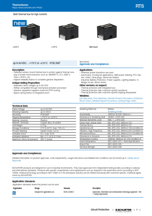
1SMD thermal fuse for high currents>210°C>175°CWith ShuntSee below:Approvals and Compliances up to 60 VDC · >175°C or >210°C · PCB, SMTDescription- Patented surface mount thermal fuse to protect against thermal runa-way of power semiconductors such as: MOSFET's, IC's, IGBT's, Triac's, SCR's, etc.- Highest reliability thanks to complete galvanic Separation.Unique Selling Proposition- Separates rated voltages up to 60 VDC- Reflow compatible through mechanical activation procedure - Galvanic separation happens inside the RTS housing - Space-saving thanks to integrated shuntApplications- Wherever power transistors are used- Automotive: Cooling fan applications, ABS power steering, PTC hea-ters, HVAC, Glow plugs, Diesel fuel heaters- Industrial: Battery Protection, Power supplies, Lighting ballasts, H-Bridge circuits, Motor driversOther versions on request- Thermal protection with integrated fuse- Thermal protection with customer specific resistance- Thermal protection with customer specific tripping temperatureWeblinkspdf data sheet , html datasheet , General Product Information , Distributor-Stock-Check , Detailed request for product , Landing Page , VideoT echnical DataRated Voltage up to 60 VDC Breaking Capacity up to 400 A MountingPCB,SMTTripping temperature >175°C or >210°C Material: Housing PlasticsMaterial: Terminals Copper alloy, tin-plated Unit Weight0.75 gStorage Conditions 0 °C to 40 °C, max. 70% r.h.Product Marking Variant Code, Lot no.Activation force Fa = max. 50 NActivation distanceSa = 1.1 +0.3/-0.1 mm Maximum reflow temperature260 °C (peak)Soldering MethodsReflowSoldering ProfileSolderabilityJESD22-B102E, Method 1 Resistance to Soldering Heat JEDEC J-STD-020 Moisture Sensitivity Level MSL 1, J-STD-020Damp heat, steady state MIL-STD-202, Method 103Thermal Shock MIL-STD-202, Method 107Operational LifeMIL-STD-202, Method 108 Condition D Vibration, High Frequency MIL-STD-202, Method 204 Condition D Mechanical Shock MIL-STD-202, Method 213 Condition B Resistance to Solvents MIL-STD-202, Method 215Temperature Cycling JESD22, Method JA-104 Condition G Flame Retardance AEC-Q200-001 + SAG Specification Board FlexAEC-Q200-005 Terminal StrengthAEC-Q200-006Approvals and CompliancesDetailed information on product approvals, code requirements, usage instructions and detailed test conditions can be looked up in Details about ApprovalsSCHURTER products are designed for use in industrial environments. They have approvals from independent testing bodies according to national and international standards. Products with specific characteristics and requirements such as required in the automotive sector according to IATF 16949, medical technology according to ISO 13485 or in the aerospace industry can be offered exclusively with customer-specific, individual agree-ments by SCHURTER.Application standardsApplication standards where the product can be usedOrganizationDesignStandardDescriptionDesigned for applications acc.IEC/UL 62368-1Audio/video, information and communication technology equipment - Part 1: Safety requirementsCompliancesThe product complies with following Guide LinesIdentification Details InitiatorDescriptionRoHS SCHURTER AGDirective RoHS 2011/65/EU, Amendment (EU) 2015/863REACH SCHURTER AG On 1 June 2007, Regulation (EC) No 1907/2006 on the Registration,Evaluation, Authorization and Restriction of Chemicals 1 (abbreviated as"REACH") entered into force.AEC Q200Automotive SCHURTER AG AEC-Q200 is a test standard for passive components used in automotiveapplications. SCHURTER tests components according to the customer'sagreement and is certified according to IATF 16949.Dimension [mm]Reflow soldering pads4.82.98.72.92.94.82.17.12.12.9Without ShuntWith Shunt Activation statusDeactivated:Before reflow the activation buttonshould not be manipulated with a forcegreater 5 newton.Activated:Activation after reflow is necessary forthe tripping functionality of the RTS.This activation is done by mechanicallypressing the activation button with max50 newton.Activation specification23BatteryLoadheat source(e.g. failed Power-FET)ThermofuseDerating CurvesDerating Curve without Shunt (RTS-AC100)O p e r a t i n g c u r r e n t [A ]Derating Curve with Shunt (RTS-AS500)O p e r a t i n g c u r r e n t [A ]Derating Curve without Shunt (RTS-BC100)O p e r a t i n g c u r r e n t [A]Derating Curve with Shunt (RTS-BS500)O p e r a t i n g c u r r e n t [A ]Design-In Principles> The RTS should be placed as close as possible to the heatsource (power semiconductor).> Max. nominal current depends on ambient temperature and on the PCB track implementation (see Derating Curves).> The derating curves were generated using a PCB acc. to IEC 60127-4 with a layer width of 20 mm.> If operating current is higher than allowed, consider using two RTS in parallel. This doubles the max. current value in the derating curve.Temperature Uniformity of ResistanceD e v i a t i o n o f r e s i s t a n c e [%]70503010-10-30-40 -10 20 50 80 110 150Ambient Temperature [°C]Packaging Unit acc. IEC 60286-3 Type 2a 100 pcs. in tape [W: 16mm and P1: 12mm] on reel [A: 18cm]750 pcs. in tape [W: 16mm and P1: 12mm] on reel [A: 33cm]The specifications, descriptions and illustrations indicated in this document are based on currentinformation. All content is subject to modifications and amendments. Information furnished is believed3.11.2214。
Mexico MS303-DSS三相手动电机控制器说明书
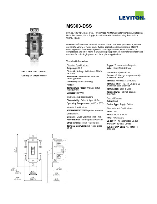
UPC Code: ************ Country Of Origin:Mexico MS303-DSS30 Amp, 600 Volt, Three-Pole, Three Phase AC Manual Motor Controller, Suitable as Motor Disconnect, Short Toggle, Industrial Grade, Non-Grounding, Back & Side Wiring, - BlackPowerswitch® Industrial Grade AC Manual Motor Controllers provide safe, reliable control of a variety of motor loads. Typical applications include manual ON/OFF switching control of conveyor systems, pumping machines, HVAC systems, air compressors and other heavy manufacturing equipment. These motor controllers are available for both single-phase and three-phase applications.Technical InformationElectrical SpecificationsAmperage: 30 ADielectric Voltage: Withstands 2200Vfor 1 min.Endurance: 6,000 cycles inductivemotor type loadGrounding: Non-GroundingPole: 3Temperature Rise: 50ºC Max at fullrated currentVoltage: 600 VACEnvironmental SpecificationsFlammability: Rated V-0 per UL 94Operating Temperature: -40°C to 60°CMaterial SpecificationsBase Material: Thermoplastic PolyesterColor: BlackContacts: Silver-Cadmium .031 ThickFace Material: Thermoplastic PolyesterStrap Material: Nickel Plated BrassTerminal Screws: Nickel-Plated Brass10-32Toggle: Thermoplastic PolyesterYoke: Nickel-Plated BrassMechanical SpecificationsProduct ID: Ratings are permenantlymarked on deviceTerminal Accom.: #10-#8 AWGTerminal ID: T1, T2, T3, L1, L2 & L3marked on back of deviceTermination: Back & SideTorque Range: 25 inch poundsmaximumProduct FeaturesColor: BlackDevice Type: Toggle SwitchStandards and CertificationsANSI: C-73NEMA: WD-1 & WD-6NOM: NOM-ANCEUL 60947-4-1: supersedes UL 508Warranty: 10-Year LimitedcUL per CSA C22.2 No. 111: File#E63969Leviton Manufacturing Co., Inc.201 North Service Road, Melville, NY 11747Telephone: +1-800-323-8920 · FAX: +1-800-832-9538 · Tech Line (8:30AM-7:30PM E.S.T. Monday-Friday): +1-800-824-3005Leviton Manufacturing of Canada, Ltd.165 Hymus Boulevard, Pointe Claire, Quebec H9R 1E9 · Telephone: +1-800-469-7890 ·FAX: +1-800-824-3005 · /canadaLeviton S. de R.L. de C.V.Lago Tana 43, Mexico DF, Mexico CP 11290 · Tel.: (+52)55-5082-1040 · FAX: (+52)5386-1797 · .mxVisit our Website at: © 2018 Leviton Manufacturing Co., Inc. All Rights Reserved. Subject to change without notice.Leviton has a global presence.If you would like to know where your local Leviton office is located please go to:/international/contacts/。
DP3000厂站自动化系统说明书1资料
DPR321CM通信服务器为DP3000厂站自动化系统通信管理单元。采用以太网或控制局域网直接和网上测量控制装置,保护装置等其他自动化智能设备交换数据。还具有多个串行通信口和调制解调器接口,能同时与多个主站或其他串行通信设备通信。
通信服务器按照功能模块划分为上位机模块和下位机模块两部分。
3) 串行通信接口
DP3000厂站综合自动化系统的通信服务器具备多个串行通信接口,接口型式有RS485、RS232、RS422等。可用于对调度主站的信息传输(由DPR321CM的上位机模块实现),或者用于与智能装置(IED)交换信息,由DPR321CM的下位机模块桥接到站内主干网。
与主站、智能装置(IED)之间的通信,支持不同形式的通信规约。
DPR300AS系列同期装置见《DPR300AS系列数字式自动准同期装置说明书》;
DPR301HT备用电源快速切换装置见《DPR301HT数字式备用电源快速切换装置说明书》;
DPR320AT系列数字式备用电源自投装置装置见《DPR320AT系列数字式备用电源自投装置说明书》;
DPR370系列低压保护控制装置见《DPR370系列数字式综合保护装置》;
2.2厂站层
DP3000厂站自动化系统厂站层包括:
1)DPS301M厂站自动化监控系统
DPS301M厂站自动化监控系统是我公司根据国内外厂站自动化的最新发展趋势而开发的厂站综合自动化监控管理单元,可广泛应用于厂站的自动化系统。本系统结合实际情况,在总结国内外先进的控制和数据采集系统基础上设计,利用网络技术打破了厂站自动化系统中信息流通的瓶颈,保证了系统的实时性,所有模块均用面向对象的程序设计方法,系统易于维护,扩展方便。系统完全摆脱了对具体硬件平台的依赖,可分别支持微软的WINDOWS NT/2000/XP等多种操作平台,配置方便、灵活。系统采用了国际通用的标准关系型商用数据库管理系统Microsoft SQL SERVER2000,采用国际国内流行的面向对象的三层模型结构(表示层、功能层和数据层),大大提高了系统的可缩放性、可维护性以及安全性,更加利于变更、维护应用技术规范。系统集成了各种先进的软件技术,具有开放的支撑环境,良好的维护性和可扩展性,提供了一个安全可靠的、能提供各种高级服务的开放式基础平台,与运行在该平台之上的多个相对独立的应用子系统一起组成一个符合现代化厂站监控、管理要求的,分布式、开放式、模块化、可扩充的综合自动化监控、管理系统。
RS-301ON三范围在线氢气纯度分析仪中文说明书

RS-301 ON 三范围氢气纯度分析仪操作手册河南省日立信电子有限公司目录第一章概述 (1)简言 (1)传感单元 (1)RS-301ON控制单元 (3)操作原理 (4)第二章技术参数 (6)第三章操作说明 (7)安装 (7)1:准备 (7)2:采样点及采样管路的连接 (7)3:电气连接 (9)4:安装完毕通电检查 (9)校准 (10)分析仪的校准 (10)第四章注意事项和维护 (13)附录 1:RS-301ON设置和校准系统流程图 (14)附录2:RS-301ON采样系统 (15)附图4:RS-301ON防尘帽现场连接示意图 (16)第一章概述简言RS-301ON三范围H2和CO2热导分析仪/指示仪使用美国HONEYWELL公司的OEM传感器,它提供了发电机置换、运转三个过程的测量:a)范围1:CO2在Air(空气)中b)范围2:CO2在H2中c) 范围3:H2在Air中RS-301ON氢气纯度分析仪由三个基本部件组成:传感单元(变送器),控制单元(图1-1)和采样系统。
控制单元、传感单元和采样系统出厂前已经被集成到一个机柜中,一体化的机柜可安装到现场。
传感单元接受被测气流,测出采样气体浓度,将一个电信号传给控制单元。
分析仪的现场管路的安装仅需一根Φ6(不锈钢卡套连接)的进气口管和一根Φ6(不锈钢卡套连接)的出气口管,电气的连接仅需输入一路AC220V电源、输出一路模拟信号和两路开关信号即可完成,既提高了系统的灵活性,又降低了安装成本。
控制单元传感单元图1-1 RS-301ON 数字分析仪控制单元可输出一个电流信号给远距离的DCS系统或上位机。
控制单元有一或两个可选报警功能,当控制单元检测到报警信号,报警继电器动作使外部报警器报警,或者继电器动作终断系统。
1.2 传感单元RS-301ON三范围热导纯度分析仪的传感组件装在一个防爆罩内,防爆罩为一牢固铸铝结构,它保证了传感器在恶劣环境下也能可靠工作。
SF301 Datasheet

最小 2.2
典型 2.5
最大 2.7
单位 VPP
- 0.13 0.3 %
3
6
%
Байду номын сангаас
85
89
DB
89
93
DB
95
97
DB
80
89
92
DB
85
DB
0
0.2 uS
Copyright 2.01 Semifly Technologic
4
SF301
8.典型电路应用图
SEMIFLY
Copyright 2.01 Semifly Technologic
输入数据必须是二进制码格式,并且高位先进。当 WS 为低时,输入数据将 被移至右输入缓存。当 WS 为高时,输入数据将被移至左输入缓存。当所有的输 入缓存稳定后,这些经过缓冲的数据才被提供给 DAC,这样就能解决两输出通道 相移问题。
DAC 的输出由一个 16 位的 R-2R 梯形电阻网络产生,这个信号有左右两个运 算放大器构成的跟随器驱动输出。
1.8
GND
典型 5 13 2.2 1.2
最大 6 18 VCC 1.8
单位 V mA V V
Copyright 2.01 Semifly Technologic
3
SF301
时序特性
参数 位时钟 字时钟 输入数据速率 高电平宽 上升沿宽 下降沿宽
SEMIFLY
符号 FBCK FWS FDIN th tr tf
I
WS
I
DIN
I
GND
VDD
LCH
O
NC
RCH
O
描述 串位时钟输入 字选时钟输入 数据输入 地 +5V 电源 左输出通道
- 1、下载文档前请自行甄别文档内容的完整性,平台不提供额外的编辑、内容补充、找答案等附加服务。
- 2、"仅部分预览"的文档,不可在线预览部分如存在完整性等问题,可反馈申请退款(可完整预览的文档不适用该条件!)。
- 3、如文档侵犯您的权益,请联系客服反馈,我们会尽快为您处理(人工客服工作时间:9:00-18:30)。
DSS301SL00BDSSDSS-601MDSS-401M DSS-351M DSS-301LDSS-201MUL 497B 2UL600V 480 7201 DOC 1cycle 10 1000 sec. 1KV-12times, 100 1000 sec. 1KV-12times respectively.2 UL Standard UL 497B File No. E175280 N400V 320 480 350V 280 420 100M min.1pF max.DOC1 1 DOC 1cycle300V 255 345 200V 160 240 DC 100VDC 250V500AFAX ULPart number system■Features●Surge protection for telephone lines.(telephone, modem, facsimile etc.)●Surge protection for telecommunication lines.(computer etc.)●Some models are recognized by UL.SeriesPart numberUL recognized DC spark-overvoltage Vs Insulation resistanceIRElectrostatic capacitance 1kHz-6V max.Surge life testSurge current capacity 8/20µsec.SURGE ABSORBERDSSV 301VsYDL1 FCC10/560 sec. 100A ±3times, 10/160 sec. 200A ±3times2 DOC 1cycle 10/1000 sec. 1KV-12times, 100/1000 sec. 1KV-12times respectively.3 UL Standard UL 497A File No. E131010 NDSSVDSSV-401M-T5DSSV-301L-T5DSSV-401M-YD DSSV-301L-YDUL 497A 3ULDC spark-overvoltage VsInsulation resistanceIRElectrostatic capacitance 1kHz-6V max.C400V 320 480300V 255 345 100M min.2pF max.Surge life testDOC1 2 400V 320 480 300V 255 345 DSSV-201M-YD 200V 160 240 DC 250VDC 100V DC 250V DC 100V300A400AFCC 1 Surge current capacity 8/20µsec.FAX UL1459 CSA-22.2 No.225-M90SeriesPart numberUL recognized DOC 1cycle 2)FCC cycle 1)CharacteristicsPart number systemDSSV Series ■Features●Protects telephone line equipment (telephone, modem, facsimile etc.) against surge and overvoltage (UL1459, CSA-22.2 No. 225-M90).SURGE ABSORBER–301L, DSSV–301L–YD, DSSV–301L–T5–401L, DSSV–401M–YD, DSSV–401M–T5Varistor 270V Varistor 390VAC600V–40A–1.50sec.AC600V–7A–5sec.DSSV–301L–YD, DSSV–401M–YD, DSSV–301L–T5, DSSV–401M–T5AC600V–2.2A–30min.–C22.2 No.225–M90Original waveform Absorption waveformSurge absorption characteristicsOvervoltage cut off properties of DSSV typePart number Applied conditions Rate of ignition Overvoltage testing is required in both UL1459 and CSA–C22.2 No.225–M90. The DSSV is effective in protecting against these overvoltage conditions by opening the circuit.SURGE ABSORBER2700, 3000V 2DSS-272M AC1200V-3 DSS-302M AC1500V-1 AC100MUL1414 UL1449, CSA, TÜVAC TV VTRT R GND ACDSS272 VsMA22R1Approved if used together with an UL approved varistor (V1mA м270V, D м 5mm), electrically connected in series by means such as twist and soldering, staking, welding etc.2Approved if used together with a varistor (AC125V : V1mA м270V, D м 5mm, AC250V : V1mA м470V, D м 5mm), electrically connected in series by means such as twist and soldering, staking, welding etc.3Approved if used together with a varistor (V1mA м470V, D м 5mm), electrically connected in series by means such as twist and soldering, staking, welding etc.4 567 Ü●High DC spark-over voltage in spite of compact size (2types; 2700, 3000V) .●DSS-272M and DSS-302M each correspond to 1200volts rms 3seconds or 1000volts rms 1minute and 1500volts rms 1minute AC withstanding voltage tests respectively.●Quick response for surge voltage and low limiting voltage.●Small capacitance and excellent insulation resistance (100M Ωmin)●Stable for repeated electrostatic test conditions and environmental fluctu-ation.●No polarity.●No dark effect.●This series is recognized under UL 1414, UL1449, CSA and TÜV.●AC Adaptor.●Antenna-circuit of TV, VCR.●Communication line. (If T, R~GND AC withstanding test is required.)SeriesDC Spark-over DC Spark-over Taping formTaping dimensionsPacking formPart number system■Features■Typical applicationsSURGE ABSORBER–272M–3 –2 –1–302M–3 –2 –1––272M–302MDischargevoltage(V)Discharge current(A)Arc discharge regionGlow discharge regionDischargevoltage(V)Discharge current(A)Arc discharge regionGlow discharge regionOriginal waveform1.2/50µsec.–10kVCharacteristicsSurge absorption characteristicsDSS–272M Absorption waveformDSS–302M Absorption waveformSURGE ABSORBERS0.8 0.8max.t3.2 3.2min.R Z 1.0 1.0max.1.2 1.2max.1.0 1.0max. 1.2 1.2max.T 6.0 1.0L 1-L 21 1max.P5.0 0.5A21A11WDSP, DSP 26 1.5 0.052 2.0 1.01 1max.10.0 0.5A22A12DSS, DSS 26 1.5 0.052 2.01.0D 04.0 0.2H 132.2 32.2max.H 016.0 0.5W 19.0 0.5W18.0F 5.0 0.5P 26.35 1.3P 1 3.85 0.5P 012.7 0.3P 12.7 1.0 DSPDSS1.0 0.5TapingAxial tapingTerminal must not project from tape.SymbolDSP, High voltage DSP(mm)DSS, High voltage DSS(mm)Radial taping( High voltage DSP and high voltage DSS is not provided in this form.)Symbol DSP Dimensions (mm)DSS Dimensions (mm)hRadial tapingSMD TapingPlastic carrier tapeReelABC DEF G HJKLt1SURGE ABSORBERSURGE ABSORBERC335mmB183mm A 48mm C04FC 400max W68mmB 35min A14minDA53 DSADSP DSSPacking quantity·Packing form Bulk <S00B >Ammo pack <A21F·A22F >Ammo pack <C04F >C350B 254A200D04F-1 Ammo pack <DB60>Ammo pack <A11F·A12F >Reel <A21R·A22R >Axial taping (in reel)A21R:4000pcs/reelC04R:3000pcs/reelAxial taping (in box)Radial taping (in reel)Radial taping (in box)A21F:2000pcs/boxAxial taping (in box)A11F:2000pcs/box Bulk packing in plastic bagS00B:200pcs/bag:500pcs/bagF type:100pcs/bagForm DA53/Unit quantity DSA/Unit quantityDSP, High voltage DSP/Unit quantity DSS, High voltage DSS/Unit quantityA22R:3000pcs/reelA22F:1000pcs/boxA12F:1000pcs/box A type:100pcs/bagS type:200pcs/bag-E15E:100pcs/bag -E25E:100pcs/bag-05F25:100pcs/bag -U10T:100pcs/bag:Axial taping (in reel)Axial taping (in box)Radial taping (in reel)SMD taping (in reel)Radial taping (in box)Axial taping (in box)Bulk packing in plastic bagFormS00B:200pcs/bagB type:200pcs/bagDA38 DA38/Unit quantityA21F:800pcs/boxDE37DE37/Unit quantity DB60 DB60/Unit quantity CSA30 CSA30/Unit quantityA22F:1000pcs/boxA12F:1000pcs/boxSURGE ABSORBER■Features of the Micro-Gap■Test Observance LabSURGE ABSORBER28元器件交易网。
