HTB-52M8中文资料
HMBT8050中文资料

HMBT8050中文资料Page No. : 1/3HMBT8050NPN EPITAXIAL TRANSISTORDescriptionThe HMBT8050 is designed for general purpose amplifier applications.FeaturesHigh DC Current hFE=150-400 at IC=150mA ? Complementary to HMBT8550Absolute Maximum RatingsMaximum TemperaturesStorage Temperature........................................................................................... -55 ~ +150 °C Junction Temperature.................................................................................... +150 °C Maximum ? Maximum Power DissipationTotal Power Dissipation (Ta=25°C)............................................................................... 225 mW ? Maximum Voltages and Currents (Ta=25°C)VCBO Collector to Base Voltage......................................................................................... 25 V VCEO Collector to Emitter Voltage...................................................................................... 20 V VEBO Emitter to Base Voltage.............................................................................................. 5 V IC CollectorCurrent (700)mACharacteristics (Ta=25°C)Symbol Min.Typ.Max.Unit Test ConditionsBVCBO 25--V IC=10uA, IE=0BVCEO 20--V IC=1mA, IB=0BVEBO 5--V IE=10uA, IC=0ICBO --1uAVCB=20V. IE=0*VCE(sat)--500mV IC=500mA, IB=50mA VBE(on)--1V VCE=1V, IC=150mA *hFE 150-500VCE=1V, IC=150mA fT 150--MHz VCE=10V, IC=20mA, f=100MHz Cob--10pFVCB=10V, f=1MHz*Pulse Test: Pulse Width ≤380us, Duty Cycle ≤2%Classification Of hFERank D9D D9E Range150-300250-500Page No. : 2/3 Characteristics CurvePage No. : 3/3SOT-23 Dimension*: TypicalInches MillimetersInches MillimetersDIM Min.Max.Min.Max.DIM Min.Max.Min.Max.A 0.11020.1204 2.80 3.04J0.00340.00700.0850.177B 0.04720.0630 1.20 1.60K 0.01280.02660.320.67C 0.03350.05120.89 1.30L0.03350.04530.851.15D 0.01180.01970.300.50S 0.08300.10832.10 2.75G 0.06690.0910 1.70 2.30V0.00980.02560.250.65H0.00050.00400.0130.10Notes: 1.Dimension and tolerance based on our Spec. dated Sep. 07,1997.2.Controlling dimension: millimeters.3.Maximum lead thickness includes lead finish thickness, and minimum lead thickness is the minimum thickness of basematerial.4.If there is any question with packing specification or packing method, please contact your local HSMC sales office.Material:Lead: 42 Alloy; solder platingMold Compound: Epoxy resin family, flammability solid burning class: UL94V-0Important Notice:All rights are reserved. Reproduction in whole or in part is prohibited without the prior written approval of HSMC.? HSMC reserves the right to make changes to its products without notice.HSMC semiconductor products are not warranted to be suitable for use in Life-Support Applications, or systems.HSMC assumes no liability for any consequence of customer product design, infringement of patents, or application assistance.Head Office And Factory:Head Office (Hi-Sincerity Microelectronics Corp.): 10F.,No. 61, Sec. 2, Chung-Shan N. Rd. Taipei Taiwan R.O.C.Tel: 886-2-25212056 Fax: 886-2-25632712, 25368454Factory 1: No. 38, Kuang Fu S. Rd., Fu-Kou Hsin-Chu Industrial Park Hsin-Chu Taiwan. R.O.C Tel: 886-3-5983621~5 Fax: 886-3-5982931。
BSP52中文资料

BSP52Absolute Maximum Ratings* T A =25°C unless otherwise noted* These ratings are limiting values above which the serviceability of any semiconductor device may be impaired.NOTES:1)These ratings are based on a maximum junction temperature of 150°C.2)These are steady state limits. The factory should be consulted on applications involving pulsed or low duty cycle operations.Electrical Characteristics T A =25°C unless otherwise notedThermal Characteristics T A =25°C unless otherwise notedSymbol ParameterValue Units V CES Collector-Emitter Voltage 80V V CBO Collector-Base Voltage 90V V EBO Emitter-Base Voltage 5V I C Collector Current- Continuous800mA T J , T STGOperating and Storage Junction Temperature Range- 55 ~ +150°CSymbolParameterTest ConditionsMin.Typ.Max.Units Off Characteristics V (BR)CBO Collector-Base Breakdown Voltage I C = 100µA, I E = 090V V (BR)EBO Emitter-Base Breakdown Voltage I E = 10µA, I C = 05V I CES Collector Cutoff Current V CE = 80V, V BE = 010µA I EBO Emitter Cutoff Current V EB = 4.0V, I C = 010µAOn Characteristicsh FE DC Current GainI C = 150mA, V CE = 10V I C = 500mA, V CE = 10V 10002000V CE (sat)Collector-Emitter Saturation Voltage I C = 500mA, I B = 0.5mA 1.3V V BE (sat)Base-Emitter Saturation VoltageI C = 500mA, I B = 0.5mA1.9VSymbol ParameterMax.Units P D Total Device Dissipation Derate above 25°C10008.0mW mW/°C R θJAThermal Resistance, Junction to Ambient125°C/WBSP52NPN Darlington Transistor•This device is designed for applications requiring extremly high current gain at collector currents to 500mA.•Sourced from process 03.SOT-22312431. Base 2. Collector 3. EmitterBSP52TRADEMARKSThe following are registered and unregistered trademarks Fairchild Semiconductor owns or is authorized to use and is not intended to be an exhaustive list of all such trademarks.DISCLAIMERFAIRCHILD SEMICONDUCTOR RESERVES THE RIGHT TO MAKE CHANGES WITHOUT FURTHER NOTICE TO ANY PRODUCTS HEREIN TO IMPROVE RELIABILITY, FUNCTION OR DESIGN. FAIRCHILD DOES NOT ASSUME ANY LIABILITY ARISING OUT OF THE APPLICATION OR USE OF ANY PRODUCT OR CIRCUIT DESCRIBED HEREIN;NEITHER DOES IT CONVEY ANY LICENSE UNDER ITS PATENT RIGHTS, NOR THE RIGHTS OF OTHERS.LIFE SUPPORT POLICYFAIRCHILD’S PRODUCTS ARE NOT AUTHORIZED FOR USE AS CRITICAL COMPONENTS IN LIFE SUPPORT DEVICES OR SYSTEMS WITHOUT THE EXPRESS WRITTEN APPROVAL OF FAIRCHILD SEMICONDUCTOR CORPORATION.As used herein:1. Life support devices or systems are devices or systems which, (a) are intended for surgical implant into the body,or (b) support or sustain life, or (c) whose failure to perform when properly used in accordance with instructions for use provided in the labeling, can be reasonably expected to result in significant injury to the user.2. A critical component is any component of a life support device or system whose failure to perform can be reasonably expected to cause the failure of the life support device or system, or to affect its safety or effectiveness.PRODUCT STATUS DEFINITIONS Definition of TermsDatasheet Identification Product Status DefinitionAdvance InformationFormative or In Design This datasheet contains the design specifications for product development. Specifications may change in any manner without notice.PreliminaryFirst ProductionThis datasheet contains preliminary data, andsupplementary data will be published at a later date.Fairchild Semiconductor reserves the right to make changes at any time without notice in order to improve design.No Identification Needed Full ProductionThis datasheet contains final specifications. Fairchild Semiconductor reserves the right to make changes at any time without notice in order to improve design.Obsolete Not In ProductionThis datasheet contains specifications on a product that has been discontinued by Fairchild semiconductor.The datasheet is printed for reference information only.FASTr™FRFET™GlobalOptoisolator™GTO™HiSeC™I 2C™ISOPLANAR™LittleFET™MicroFET™MicroPak™MICROWIRE™OPTOLOGIC ®OPTOPLANAR™PACMAN™POP™Power247™PowerTrench ®QFET™QS™QT Optoelectronics™Quiet Series™SLIENT SWITCHER ®SMART START™SPM™Stealth™SuperSOT™-3SuperSOT™-6SuperSOT™-8SyncFET™TinyLogic™TruTranslation™UHC™UltraFET ®VCX™ACEx™Bottomless™CoolFET™CROSSVOLT ™DOME™EcoSPARK™E 2CMOS™EnSigna™FACT™FACT Quiet series™FAST ®。
BSP52;中文规格书,Datasheet资料
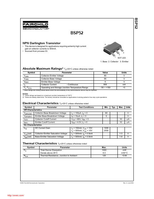
BSP52Absolute Maximum Ratings* T A =25°C unless otherwise noted* These ratings are limiting values above which the serviceability of any semiconductor device may be impaired.NOTES:1)These ratings are based on a maximum junction temperature of 150°C.2)These are steady state limits. The factory should be consulted on applications involving pulsed or low duty cycle operations.Electrical Characteristics T A =25°C unless otherwise notedThermal Characteristics T A =25°C unless otherwise notedSymbol ParameterValue Units V CES Collector-Emitter Voltage 80V V CBO Collector-Base Voltage 90V V EBO Emitter-Base Voltage 5V I C Collector Current- Continuous800mA T J , T STGOperating and Storage Junction Temperature Range- 55 ~ +150°CSymbolParameterTest ConditionsMin.Typ.Max.Units Off Characteristics V (BR)CBO Collector-Base Breakdown Voltage I C = 100µA, I E = 090V V (BR)EBO Emitter-Base Breakdown Voltage I E = 10µA, I C = 05V I CES Collector Cutoff Current V CE = 80V, V BE = 010µA I EBO Emitter Cutoff Current V EB = 4.0V, I C = 010µAOn Characteristicsh FE DC Current GainI C = 150mA, V CE = 10V I C = 500mA, V CE = 10V 10002000V CE (sat)Collector-Emitter Saturation Voltage I C = 500mA, I B = 0.5mA 1.3V V BE (sat)Base-Emitter Saturation VoltageI C = 500mA, I B = 0.5mA1.9VSymbol ParameterMax.Units P D Total Device Dissipation Derate above 25°C10008.0mW mW/°C R θJAThermal Resistance, Junction to Ambient125°C/WBSP52NPN Darlington Transistor•This device is designed for applications requiring extremly high current gain at collector currents to 500mA.•Sourced from process 03.SOT-22312431. Base 2. Collector 3. EmitterBSP52TRADEMARKSThe following are registered and unregistered trademarks Fairchild Semiconductor owns or is authorized to use and is not intended to be an exhaustive list of all such trademarks.DISCLAIMERFAIRCHILD SEMICONDUCTOR RESERVES THE RIGHT TO MAKE CHANGES WITHOUT FURTHER NOTICE TO ANY PRODUCTS HEREIN TO IMPROVE RELIABILITY, FUNCTION OR DESIGN. FAIRCHILD DOES NOT ASSUME ANY LIABILITY ARISING OUT OF THE APPLICATION OR USE OF ANY PRODUCT OR CIRCUIT DESCRIBED HEREIN;NEITHER DOES IT CONVEY ANY LICENSE UNDER ITS PATENT RIGHTS, NOR THE RIGHTS OF OTHERS.LIFE SUPPORT POLICYFAIRCHILD’S PRODUCTS ARE NOT AUTHORIZED FOR USE AS CRITICAL COMPONENTS IN LIFE SUPPORT DEVICES OR SYSTEMS WITHOUT THE EXPRESS WRITTEN APPROVAL OF FAIRCHILD SEMICONDUCTOR CORPORATION.As used herein:1. Life support devices or systems are devices or systems which, (a) are intended for surgical implant into the body,or (b) support or sustain life, or (c) whose failure to perform when properly used in accordance with instructions for use provided in the labeling, can be reasonably expected to result in significant injury to the user.2. A critical component is any component of a life support device or system whose failure to perform can be reasonably expected to cause the failure of the life support device or system, or to affect its safety or effectiveness.PRODUCT STATUS DEFINITIONS Definition of TermsDatasheet Identification Product Status DefinitionAdvance InformationFormative or In Design This datasheet contains the design specifications for product development. Specifications may change in any manner without notice.PreliminaryFirst ProductionThis datasheet contains preliminary data, andsupplementary data will be published at a later date.Fairchild Semiconductor reserves the right to make changes at any time without notice in order to improve design.No Identification Needed Full ProductionThis datasheet contains final specifications. Fairchild Semiconductor reserves the right to make changes at any time without notice in order to improve design.Obsolete Not In ProductionThis datasheet contains specifications on a product that has been discontinued by Fairchild semiconductor.The datasheet is printed for reference information only.FASTr™FRFET™GlobalOptoisolator™GTO™HiSeC™I 2C™ISOPLANAR™LittleFET™MicroFET™MicroPak™MICROWIRE™OPTOLOGIC ®OPTOPLANAR™PACMAN™POP™Power247™PowerTrench ®QFET™QS™QT Optoelectronics™Quiet Series™SLIENT SWITCHER ®SMART START™SPM™Stealth™SuperSOT™-3SuperSOT™-6SuperSOT™-8SyncFET™TinyLogic™TruTranslation™UHC™UltraFET ®VCX™ACEx™Bottomless™CoolFET™CROSSVOLT ™DOME™EcoSPARK™E 2CMOS™EnSigna™FACT™FACT Quiet series™FAST ®分销商库存信息: FAIRCHILDBSP52。
哈伯斯特固定宽度导轨说明书

Description Guide rail of fixed width inclusive a covering plate and 2 metal clamps.Joining system齒接Belt/tape thickness max.3mm 0.10inch Dimensions (Lx x H )150x 7mm 5.91x 0.28inch Guide rail kit 42 mmH080672226Guide rail kit 55 mmH080672225Guide rail kit 60 mmH080672224Guide rail kit 74 mmH080672223Guide rail kit 80 mmH080672222Guide rail kit 90 mmH080672221Guide rail kit 100 mmH080672220Guide rail kit 42 mm52 mm ( 2.05 inch )Guide rail kit 55 mm65 mm ( 2.56 inch )Guide rail kit 60 mm70 mm ( 2.76 inch )Guide rail kit 74 mm84 mm ( 3.31 inch )Guide rail kit 80 mm90 mm ( 3.54 inch )Guide rail kit 90 mm100 mm ( 3.94 inch )Guide rail kit 100 mm 110 mm ( 4.33 inch )分類GFT 工具次分類Accessories 海關稅號84779080声明产品应用声明(适用于所有哈伯斯特 Habasit 产品及所有产品资料表上提到的)“这个声明是由哈伯斯特 Habasit 及代表其附属公司,董事,雇员,代理人和承包商(以下统称”HABASIT“)及与本文提到的产品(”产品“)关联。
BYW52中文资料

Applications
Rectifier, general purpose
Absolute Maximum Ratings
Tj = 25_C Parameter Reverse voltage g =Repetitive peak reverse voltage Test Conditions Type BYW52 BYW53 BYW54 BYW55 BYW56 Symbol VR=VRRM VR=VRRM VR=VRRM VR=VRRM VR=VRRM IFSM IFRM IFAV PR ER i2*t Tj=Tstg Value 200 400 600 800 1000 50 12 2 1000 20 Unit V V V V V A A A W mJ A2*s °C
94 9178
tp – Pulse Length ( s )
Figure 7. Thermal Response
Dimensions in mm
∅ 3.6 max. Sintered Glass Case SOD 57 Weight max. 0.5 g Cathode Identification
Document Number 86049 Rev. 2, 24-Jun-98
元器件交易网
BYW52...BYW56
Vishay Telefunken
100 CD – Diode Capacitance ( pF ) Tj = 25°C IF – Forward Current ( A ) 10 Tj = 175°C 80 f = 0.47 MHz Tj = 25°C
Characteristics (Tj = 25_C unless otherwise specified)
HB52RF648DC-75BL中文资料

Data Sheet E0083H40 2
HB52RF648DC-B, HB52RD648DC-B
Pin Arrangement
Front Side
1pin 2pin
59pin 60pin
61pin 62pin143pin Nhomakorabea44pin
Back Side
Front side Pin No. 1 3 5 7 9 11 13 15 17 19 21 23 25 27 29 31 33 35 37 39 Signal name Pin No. VSS DQ0 DQ1 DQ2 DQ3 VCC DQ4 DQ5 DQ6 DQ7 VSS DQMB0 DQMB1 VCC A0 A1 A2 VSS DQ8 DQ9 73 75 77 79 81 83 85 87 89 91 93 95 97 99 101 103 105 107 109 111
Data Sheet E0083H40 4
HB52RF648DC-B, HB52RD648DC-B
Pin Description
Pin name A0 to A12 Function Address input Row address A0 to A12 Column address A0 to A9 BA0/BA1 DQ0 to DQ63 S0/ S1 RE CE W DQMB0 to DQMB7 CK0/CK1 CKE0/CKE1 SDA SCL VCC VSS NC Bank select address Data-input/output Chip select Row address asserted bank enable Column address asserted Write enable Byte input/output mask Clock input Clock enable Data-input/output for serial PD Clock input for serial PD Power supply Ground No connection
LXM52产品手册

Lexium LXM5208.2014Operating Manual(Translation of the original German Operating Manual)ImprintThe information provided in this documentation contains general descriptions and/ortechnical characteristics of the performance of the products contained herein. Thisdocumentation is not intended as a substitute for and is not to be used for determiningsuitability or reliability of these products for specific user applications. It is the duty ofany such user or integrator to perform the appropriate and complete risk analysis,evaluation and testing of the products with respect to the relevant specific applicationor use thereof. Neither Schneider Electric nor any of its affiliated or subsidiary com‐panies are responsible or liable for a misuse of the information contained herein. If youhave any suggestions for improvements or amendments or have found errors in thispublication, please notify us.No part of this document may be reproduced in any form or by any means, electronicor mechanical, including photocopying, without express written permission of Schneid‐er Electric.All pertinent state, regional, and local safety regulations must be observed when in‐stalling and using this product. For reasons of safety and to help ensure compliancewith documented system data, only the manufacturer should perform repairs to com‐ponents.When devices are used for applications with technical safety requirements, the rele‐vant instructions must be followed.Failure to use Schneider Electric software or approved software with our hardwareproducts may result in injury, harm, or improper operating results.Failure to observe this information can result in injury or equipment damage.© 2014 Schneider Electric. All rights reserved.2Lexium LXM52Schneider Electric 08.2014Contents Contents1About this manual 6 1.1Introduction (6)1.2Symbols, designator and display format of safety messages (7)2Safety information 9 2.1Proper use (9)2.2Qualification of Personnel (10)2.3Residual risks (11)2.3.1Electrical parts (11)2.3.2Assembly and handling (12)2.3.3Hot surfaces (12)2.3.4Magnetic and electromagnetic fields (13)2.3.5Hazardous movements (13)2.3.6PELV circuits (14)3System overview 15 3.1Logic Motion Controller (15)3.2Lexium LXM52 (16)3.3SH3 Servo motor (16)3.4Type code (17)3.5Nameplate descriptions (18)4Indicators and control elements 20 4.1Control elements and LEDs at the LXM52 (20)4.1.1Reset button (20)4.1.2State LED (21)4.1.3Port LED (21)4.1.4S3 LED (22)4.1.5DC bus LED (22)5Planning 23 5.1Electromagnetic Compatibility, EMC (23)5.2Control cabinet planning (26)5.2.1Degree of protection (26)5.2.2Mechanical and climatic environmental conditions in the control cabinet (26)5.2.3Using Cooling Units (27)Schneider Electric 08.2014Lexium LXM523Contents5.3Wiring notes (28)5.3.1Cable characteristics (28)5.3.2Cable assembly (29)5.3.3ESD protection measures (29)5.3.4Conditions for UL compliant use (29)5.3.5Fusing the mains connection (30)5.3.6Mains contactor (30)5.3.7Mains filter (30)5.3.8Mains chokes (32)5.3.9Leakage current (32)5.3.10Residual current operated protective device (33)5.3.11Parallel connection DC bus (34)5.3.12Shield connection (34)5.4Functional safety (35)5.4.1Process minimizing risks associated with the machine (35)5.4.2Inverter Enable function (36)5.4.3Setup, installation, and maintenance (39)5.4.4Application proposals (40)5.4.5Commissioning (43)5.4.6Best Practices and Prevention of Misuse (43)5.4.7Maintenance (44)5.4.8Physical environment (44)5.4.9Safety standards (45)5.5Special Conditions (46)5.5.1Low air pressure (46)6Installation and maintenance 47 6.1Commissioning (47)6.1.1Preparing commissioning (48)6.1.2Preparing the control cabinet (49)6.1.3Mechanical mounting (53)6.2Maintenance, repair, cleaning (54)6.2.1Repair (54)6.2.2Cleaning (55)6.3Spare part inventory (55)6.4Device-, parts- or cable exchange (56)6.4.1Cable replacement (59)7Technical data 60 7.1Ambient conditions (60)7.2Standards and regulations (61)7.3Mechanical and electrical data (62)7.4Electrical connections (64)7.4.1LXM52 (64)7.5Dimensions (70)4Lexium LXM52Schneider Electric 08.2014Contents8Appendix 71 8.1Contact addresses (71)8.2Product training courses (71)8.3Disposal (71)8.4EC declaration of conformity (72)8.5Optional accessory (73)8.5.15V Encoder Adapter (73)8.6Units and conversion tables (77)8.6.1Length (77)8.6.2Mass (77)8.6.3Force (77)8.6.4Power (77)8.6.5Rotation (77)8.6.6Torque (78)8.6.7Moment of inertia (78)8.6.8Temperature (78)8.6.9Conductor cross-section (78)Schneider Electric 08.2014Lexium LXM5251 About this manual1About this manual1.1IntroductionRead and understand the material contained in this manual before you work on theLXM52 for the first time. Take particular note of the safety information (see 2.3 Residualrisks). As described in section 2.2, only those persons who meet the "Selection andqualification of employees" are allowed to work at the LXM52.A copy of this manual must be available for personnel who work at the LXM52.This manual is supposed to help you use the capabilities of the LXM52 safely andproperly.Follow the instructions within this manual to:•avoid risks•reduce repair costs and downtime of the LXM52•increase the service life of the LXM52,•increase reliability of the LXM52.6Lexium LXM52Schneider Electric 08.20141.2Symbols, designator and display format of safety messagesImportant InformationNOTE Read these instructions carefully, and look at the equipment to become familiar withthe device before trying to install, operate, or maintain it. The following special mes‐sages may appear throughout this documentation or on the equipment to warn of po‐tential hazards or to call attention to information that clarifies or simplifies a procedure.The addition of this symbol to a Danger or Warning safety label indicates that an electricalhazard exists, which will result in personal injury if the instructions are not followed.This is the safety alert symbol. It is used to warn the user of potential personal injuryhazards. Obey all safety messages that follow this symbol to avoid possible injury or death.DANGERDANGER indicates an imminently hazardous situation which, if not avoided, will result in death WARNINGWARNING indicates a potentially hazardous situation which, if not avoided, can result in death CAUTIONCAUTION indicates a potentially hazardous situation which, if not avoided, can result in minor NOTICEis used to address practices not related to physical injury.1.2 Symbols, designator and display format of safety messagesSchneider Electric 08.2014Lexium LXM5271 About this manualThe following symbols and designators are used in this document:►8Lexium LXM52Schneider Electric 08.20142Safety informationThis section contains information regarding working with the LXM52. Qualified per‐sonnel working on the LXM52 must read and observe this information. The LMX52 system is conform to recognized technical safety regulations.2.1Proper useThe LMX52 system must only be installed in a closed electrical equipment (for exam‐ple, control cabinet). The closed electrical equipment must be lockable by using a keyor tool.Provide for protective measures Before installing the device, provide for appropriate protective devices in compliance with local and national standards. Do not commission components without suitable protective devices. After installation, commissioning, or repair, test the protective de‐vices used.Perform a risk evaluation concerning the specific use before operating the product and take appropriate security measures.If circumstances occur that affect the safety or cause changes to the operating be‐havior of the LXM52, then immediately shut down the LXM52 and contact your Schneider Electric contact person.Use original-equipmentonly Use only the accessories and mounting parts specified in the documentation and no third-party devices or components that have not been expressly approved by Schneid‐er Electric. Do not change the LXM52 inappropriately.The components must not be used in the following environments:Forbidden environments •In hazardous (explosive) atmospheres •In mobile, movable or floating systems •In life support systems•In domestic appliances •undergroundInstallation and operatingconditions Only use the components in accordance with the installation and operating conditions described in this documentation. The operating conditions at the installation location must be inspected and maintained in accordance with the required technical data (performance data and ambient conditions). Commissioning is prohibited until the usable machine or system in which of the LXM52 is installed meets all requirements of EC guidelines 2006/42/EC (machinery directive).In addition, the following standards, directives and regulations are to be observed:•EN ISO 13849-1:2008 Safety of machinery - Safety-related parts of control systems- Part 1: General principles for design•EN 60204-1 Safety of machinery - Electrical equipment of machines - Part 1: Gen‐eral requirements•EN ISO 12100-1 - Safety of machines - Basic terms, general principles for design - Part 1: Basic terminology, methodology•EN ISO 12100-2 - Safety of machines - Basic terms, general principles of design - Part 2: Technical guidelines•EN 50178 - Electronic equipment for use in power installations•EN 61800-3 Adjustable speed electrical power drive systems - Part 3: EMC re‐quirements and specific test methods2.1 Proper useSchneider Electric 08.2014Lexium LXM529•EN 61800-5-1 Adjustable speed electrical power drive systems - Part 5-1: Safety requirements - Electrical, thermal and energy•The generally applicable local and national safety and accident prevention regu‐lations.•The rules and regulations on accident prevention and environmental protection that apply in the country where the product is used.2.2Qualification of PersonnelTarget audi‐ence for this manual Electrical equipment must be installed, operated, serviced, and maintained only by qualified personnel. No responsibility is assumed by Schneider Electric for any con‐sequences arising out of the use of this material.Qualified per‐son A qualified person is one who has skills and knowledge related to the construction and operation of electrical equipment and the installation, and has received safety training to recognize and avoid the hazards involved.The qualified personnel must be able to detect possible hazards that may arise from parameterization, changing parameter values and generally from mechanical, electri‐cal or electronic equipment. The qualified personnel must be familiar with the stand‐ards, provisions and regulations for the prevention of industrial accidents, which they must observe when working on the drive system.Designated safety func‐tions Qualified personnel that work with designated safety functions must be trained ac‐cording to the complexity of the machines and the requirements of the EN ISO 13849-1:2008. The training has to include the production process and the relationbetween the designated safety function and the machine.Qualification guidelines are available in the following publication: Safety, Competencyand Commitment: Competency Guidelines for Safety-Related System Practitioners.IEEE Publications, ISBN 0 85296 787 X, 1999.2 Safety information10Lexium LXM52Schneider Electric 08.20142.3Residual risksHealth risks arising from the LXM52 have been reduced. However a residual risk re‐mains, since the LXM52 works with electrical voltage and electrical currents.If activities involve residual risks, a safety message is made at the appropriate points. This includes potential hazard(s) that may arise, their possible consequences, and describes preventive measures to avoid the hazard(s). The following types of warnings concerning residual risks which cannot be assigned to a specific handling. The struc‐ture of a warning instruction is identical to that of a safety label.2.3.1Electrical partsDANGERHAZARD OF ELECTRIC SHOCK, EXPLOSION, OR ARC FLASHOperate electrical components only with a connected protective conductor.After the installation, verify the fixed connection of the protective conductor to allelectrical devices to ensure that connection complies with the connection dia‐Before enabling the device, safely cover the live components to prevent contact.Do not touch the electrical connection points of the components when the unit isProvide protection against indirect contact (EN 50178).Disconnect/plug in Plug-in connectors of the cables and plug-in terminals on thedevice only when the system is disconnected from the power supply.Insulate the unused conductors on both ends of the motor cable because ACvoltages in the motor cable can couple to unused conductors.Failure to follow these instructions will result in death or serious injury.2.3 Residual risks2 Safety information2.3.2Assembly and handlingDANGERHAZARD OF ELECTRIC SHOCK CAUSED BY HIGH TOUCH VOLTAGE DUE TODEVICE LEAKAGE CURRENT HIGHER THAN 3.5 MA ACConnect the device via a fixed connection with the power supply network.Additionally one of the following measures should be applied:- Use a cross-section of the protective conductor of at least 10 mm(AWG 6) aluminum.- Provide an automatic disconnection of the power supply in case of a disconti‐nuity of the protective conductor.- Provide an additional terminal for a second protective conductor of the samecross-sectional area as the original protective conductor.Failure to follow these instructions will result in death or serious injury.WARNINGCRUSHING, SHEARING, CUTTING AND HITTING DURING HANDLINGObserve the general construction and safety regulations for handling and as‐Use suitable mounting and transport equipment correctly and use special toolsPrevent clamping and crushing by taking appropriate precautions.Cover edges and angles to protect against cutting damage.Wear suitable protective clothing (e.g. safety goggles, safety boots, protective Failure to follow these instructions can result in death or serious injury.2.3.3Hot surfacesCAUTIONWait until the surface temperature has cooled to allow safe contact.Wear protective gloves.Attach protective cover or touch guardFailure to follow these instructions can result in injury.2.3.4Magnetic and electromagnetic fieldsPersonnel with pacemakers must not be allowed to work within the vicinity of this typeof equipment.WARNINGMAGNETIC AND ELECTROMAGNETIC FIELDSDo not work within the vicinity of live conductors and motor permanent magnets if youhave a pacemaker or other similar sensitive medical implants.Failure to follow these instructions can result in death or serious injury.2.3.5Hazardous movementsThere can be different causes of hazardous movements:•Missing or incorrect homing of the drive•Wiring or cabling errors•Errors in the application program•Potential component errors•Potential error in the measured value and signal transmitterProvide for personal safety by primary equipment monitoring or measures. Do not rely only on the internal monitoring of the drive components. Adapt the monitoring or other arrangements and measures to the specific conditions of the installation in accordance with a risk and error analysis carried out by the system manufacturer.DANGERMISSING OR INADEQUATE PROTECTION DEVICE(S)Prevent entry to a zone of operation with, for example, protective fencing, mesh guards, protective coverings, or light barriers.Dimension the protective devices properly and do not remove them.Do not make any modifications that can degrade, incapacitate or in any way in‐validate protection devices.Before accessing the drives or entering the zone of operation, bring the drives toProtect existing work stations and operating terminals against unauthorized op‐Position EMERGENCY STOP switches so that they are easily accessible andValidate the functionality of EMERGENCY STOP equipment before start-up and during maintenance periods.Prevent unintentional start-up by disconnecting the power connection of the drive using the EMERGENCY STOP circuit or using an appropriate lock-out tag-outValidate the system and installation before the initial start-up.Avoid operating high-frequency, remote control, and radio devices close to the system electronics and their feed lines and perform, if necessary, an EMC vali‐Failure to follow these instructions will result in death or serious injury.2.3 Residual risks2.3.6PELV circuitsThe signal voltage and the control voltage of the devices are < 30 Vdc and have tobe designed as PELV circuits. In this range the specification as PELV system, ac‐cording to EN 61800-5-1 contains a protective measure against direct and indirectcontact with dangerous voltage through a implemented safe separation in the system/machine of the primary and the secondary side. We recommend to design the system/machine with a safe separation (PELV Protective-Extra-Low-Voltage).DANGERHAZARD OF ELECTRIC SHOCK BY INADEQUATE PROTECTIVE SEPARATIONOnly connect devices, electrical components or lines to the signal voltage connectorsof these components that feature a sufficient, protective separation from the con‐nected circuits in accordance with the standards (IEC 61800-5-1: Adjustable speedelectrical power drive systems - safety requirements).Failure to follow these instructions will result in death or serious injury.Achieve a safe separation in the entire process of the electric circuit.Use secondary isolating source rated 30 Vdc. Fuse in accordance with CSA-C22.2No. 248, rated max. 3 A must be connected between the source and the contacts.2 Safety information3System overviewThe control system consists of several single components, depending on its applica‐tion.Ethernet, TCP/IP, OPC, FTP, HTTP, SMS, SMTPsercos + Integrated Safety*MagelisHMILMC 100C, 101C, 106C, 201C, 212C, 216C, 300C, 400C, 600CLogic Motion ControllersSoMachineMotionIT/COMLogic MotionTM7Remote I/OTM7Remote I/OTM5 I/OMultiaxes Servo Drives LXM 62+ Power Supply Module LXM62P•••Stand-aloneServoDrivesLXM 52DistributionBoxILM 62SH3euq r o TH3SMotorLinearMotorOther field busses:• Profibus DP• CAN• Ethernet/IP• ProfinetSafety PLC SLCx00*ILx SD328BRS3TeSys ATV 312ATV 32= InverterEnable 2-channel (red small square on the device)+ Connection Module ILM62CMFigure 3-1: PacDrive 3 System overview*Safety PLC according to IEC 61508:2010 and EN ISO 13849:20083.1Logic Motion ControllerThe LMC (Logic Motion Controller), with a VxWorks real-time operating system, cen‐trally implements the PLC (Programmable Logic Controller) and motion functions. ALMC synchronizes, coordinates and creates the motion functions of a machine for amaximum of:•0 Sercos servo drives (LMC 100C)• 4 Sercos servo drives (LMC 101C)• 6 Sercos servo drives (LMC 106C)•8 Sercos servo drives (LMC 201C)•12 Sercos servo drives (LMC 212C)•16 Sercos servo drives (LMC 216C)•8 Sercos servo drives (LMC 300C)•16 Sercos servo drives (LMC 400C)•99 Sercos servo drives (LMC 600C)3.1 Logic Motion Controller3.2Lexium LXM52The stand-alone LXM52 Sercos servo amplifier is designed for servo drive solutions with independent single axes.The power electronic components of the LXM52 are fitted inside the control cabinet. The LXM52 is directly connected to the mains supply.The drive provides the phase currents required for the position control of the connected servo motors. According to the different requirements in relation to the individual servo axes of the application, the LXM52 is available in different current classes.The LXM52 simplifies the wiring in relation to the initial start-up and service cases. This also applies to the cable connection of the enclosed devices to the field. All the connectors that can be connected from the outside (power input, DC bus, 24 Vdc-supply, Sercos, motor, encoder, IOs, IO-supply, ready and inverter enable (STO)) are designed so that a fast, simple configuration on the device can be realized without tools.3.3SH3 Servo motorThe servo motors meet rigorous requirements of dynamics and precision. Five flange sizes with different torque outputs offer the right drive solution for application.high dynamicAC servo motors Because of the low inertia and a high overload capability, the motor SH3 fulfills the requirements concerning the accuracy, dynamics and efficiency.The SH3 motors are available in five different flange sizes:•SH3-055•SH3-070•SH3-100•SH3-140•SH3-205The highlights:•Developed for high dynamics and precision•Single tooth winding•compact size•high power density•Low internal moment of inertia•high overload capability•Low detent torque3 System overview3.4Type codeFigure 3-2: Type code LXM 523.4 Type code3.5Nameplate descriptionsThe technical type plates are located laterally on the housing.LXM52DD18CLabel MeaningLXM52xxxxxxxxxx Device type and UnicodeInput AC Input voltage and -current (rated- and peak value per input) Output Output voltage and -current (rated- and peak value per output) IP 20Degree of protection*)This field displays the symbols of declarations and certifications Table 3-1: Explanation of the nameplate3 System overviewThe logistic nameplate is located on the top of the housing. Figure 3-3: Logistic nameplate LXM523.5 Nameplate descriptions4Indicators and control elements4.1Control elements and LEDs at the LXM52The display of the LXM52 consists of four color LEDs that are used to display statusinformation.Figure 4-1: Diagnostic LEDs at the LXM521Reset button H1State A LED H2S3 Port 1 LED H3S3 LED H4S3 Port 2 LED H5DC bus LED4.1.1Reset button▶Press the reset button to reset and reboot the device.4 Indicators and control elements4.1 Control elements and LEDs at the LXM52 4.1.2State LEDTable 4-1: State LED4.1.3Port LEDTable 4-2: Port LED4 Indicators and control elements4.1.4S3 LEDTable 4-3: S3 LED4.1.5DC bus LEDTable 4-4: DC bus LEDThe DC bus LED is no clear display for a non-existing DC bus voltage.5Planning5.1Electromagnetic Compatibility, EMCWARNINGELECTROMAGNETIC DISTURBANCES OF SIGNALS AND DEVICESUse proper EMC shielding techniques to help prevent unintended device operation.Failure to follow these instructions can result in death or serious injury.This product meets the EMC requirements in accordance with the standard IEC61800-3:2004, provided that the EMC measures described in this manual are compliedwith during installation.Enclosurelayout The prerequisite for compliance with the specified limit values is an EMC compatible layout. Comply with the following specifications:EMC measures TargetUse galvanized or chromium-plated sub plates, bond metallic partsacross large surface areas, remove paint layer from contact surfaces.Good conductivity by surfacearea contactGround enclosure, door and sub plates by using grounding strips orgrounding cables with a cross-section of 10 mm2 (AWG 6).Reduce emission.Supplement switch devices such as contactors, relays or magneticvalves with interference suppression combinations or spark suppressorelements (e.g. diodes, varistors, RC elements).Reduces mutual interference Fit power and control components separately.Reduces mutual interferenceShielded cablesEMC measures TargetPlace cable shields on the surface, use cable clamps and groundingstrips.Reduce emission.At the control cabinet outfeed, connect the shield of all shielded cablesvia cable clamps to the sub plate across large surface areas.Reduce emission.Ground shields of digital signal cables on both sides across large surfaceareas or through conducting connector housings.Reduce interference action onsignal cables, reduce emis‐sions.Ground shield of analog signal cables directly on the device (signal in‐put), insulate the shield at the other cable end or ground the samethrough a capacitor, such as 10 nF.Reduce grounding loops bylow frequency interferences.Use only shielded motor supply cables with a copper braid and at least85% cover, ground shield on both sides across a large surface area.Specifically discharge interfer‐ence currents, reduce emis‐sions.Cable routingEMC measures TargetDo not route fieldbus cables and signal cables together with cabling fordirect and alternating voltages above 60 V in the same cable duct (field‐bus cables can be routed together with signal cables and analog cablesin the same duct). Recommendation: Routing in separated cable cutswith a distance of at least 20 cm (7.84 in.).Reduces mutual interferenceKeep the cables as short as possible. Do not install any unnecessarycable loops, short cable routing from a central grounding point in thecontrol cabinet to the external grounding connection.Reduce capacitive and induc‐tive interference couplings.5.1 Electromagnetic Compatibility, EMCEMC measures TargetInsert a potential equalization for:•large surface installation •different voltage infeeds •networking across buildings Reduce current on cable shield, reduce emissions.Use fine wire potential equalization conductor.Discharging of high frequencyinterference currents.If motor and machine are not connected in a conducting fashion, e.g. due to an insulated flange or a connection not across a full surface, the motor must be grounded via a grounding cable > 10 mm2 (AWG 6) or a ground‐ing strip.Reduce emissions, increase interference resistance.Use twisted pair for 24 Vdc signals.Reduce interference action onsignal cables, reduce emis‐sions.Voltage supplyEMC measures TargetOperate product on mains with a grounded neutral.Enable the effect of the inte‐grated mains filter. Protection circuit if there is a risk of overvoltage.Reduce risk of damage due toovervoltages.Motor and encoder cables From an EMC perspective, motor supply cables and encoder cables are particularly critical. Only use pre-configured cables, or cables with the prescribed properties, and comply with the following EMC measures.EMC measures TargetDo not install switching elements in motor cables or encoder cables.Reduces interference.Route motor cable with a distance of at least 20 cm (7.84 in.) to thesignal cables or insert shield plates between the motor supply cable andthe signal cable.Reduces mutual interferenceFor long cabling, use potential equalization cables.Reduce current on cableshield.Route motor supply cables and encoder cables without any separationpoint. 1)Reduces emission.1) If a cable must be cut through for installation purposes, the cables must be connected at the point of separation by means of screen connections and metal housing.5 Planning。
ZMM5252B中文资料(WILLAS ELECTRONIC)中文数据手册「EasyDatasheet - 矽搜」
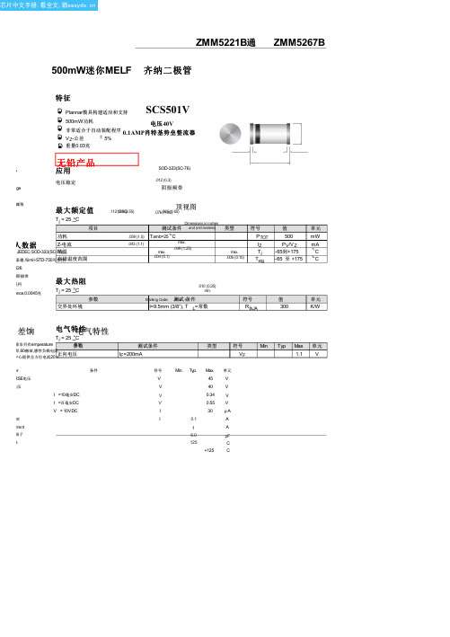
5264
ZMM5265B
62.0
58.90
65.10
185
2.0
1400
0.25
0.1
47.0
5265
ZMM5266B
68.0
64.60
71.40
230
1.8
1600
0.25
0.1
52.0
5266
ZMM5267B
75.0
71.25
78.75
270
1.7
1700
0.25
0.1
56.0
5267
1)基于直流测量达到热平衡;引线长度=9.5毫米(3/8");散热器= 30K / W热阻
5244
ZMM5245B
15.0
14.25
15.75
16
8.5
600
0.25
0.1
11.0
5245
ZMM5246B
16.0
15.20
16.80
17
7.8
600
0.25
0.1
12.0
5246
ZMM5247B
17.0
16.15
17.85
19
7.4
600
0.25
0.1
13.0
5247
ZMM5248B
18.0
类型
max. .006 (0.15)
符号
PTOT IZ Tj Tstg
值
500
PV/V Z -65到+175 –65 至 +175
单元
mW
mA °C °C
.010 (0.25) min.
Marking Code: 测JV o试r 4条件
霍巴特AM3洗盘替换零部件手册说明书

19
18
21
20
19
18
9
13
14 15 12 16 17
AM3 DISHWASHER REPLACEMENT PARTS
LOWER FRAME ASSEMBLY
PART NO.
NAME OF PART
1
743388 1.1 kW Wash Pump For 380/50/3 220/50/3
9
RR-11-03 Retaining Ring
10
743309 Throttle Plate
11
743399 Lower Manifold/Shaft Assy
12
473984 Gasket- Manifold
13
473460 Nut- Manifold
14
67500-10 "O" Ring 22.4*3.55
3
538412 Clamp- Hose 50mm
4
542337 Clamp- Hose 60mm
5
743315-1 Clamp- Hose 75mm
6
743396 Hose Adapter- Wash Pump Inlet
7
743336 Clamp- Hose 14mm
8
743397 Piping- Wash Pump Drain
22
743446-3 End Cap- Rinse Arm
AMT.
1 1 4 20 12 2 2 1 1 1 1 1 1 3 1 4 1 20 16 2 2 4
6
AM3 DISHWASHER REPLACEMENT PARTS
WASH TANK
美国武器装备大全(空军篇)
美国武器装备大全(空军篇)各位朋友们续美国武器装备大全(陆军篇)后空军篇来了空军篇将比陆军篇更为精彩。
美国空军武器分类:战斗机轰炸机侦察、运输机直升机电子战机。
美国猛禽战斗机小宇宙S/rose[383230383] 2005-09-15 21:22题目:Re:美国武器装备大全(空军篇)下面介绍:★战斗机★小宇宙S/rose[383230383] 2005-09-15 21:25题目:Re:Re:美国武器装备大全(空军篇)F-14重型战斗机F-14是为美国海军研制的双座超音速舰载多用途重型战斗机,主要任务是护航、舰队防空以及遮断和近距空中支援。
该机采用双发双垂尾变后掠中单翼气动布局,机翼的后掠角可在20度-68度范围内自动调节,有很好的低速和高速性能,全金属半硬壳式机身,广泛采用钛合金,部分采用硼复合材料。
该机有F-14A、F-14B、F-14D以及RF-14A(侦察型)等改型。
动力装置早期装两台TF30-P412涡扇发动机,自1986年起采用通用电气公司的F110-GE-400涡轮风扇发动机,单台加力推力124.5千牛。
主要机载设备休斯公司的AN/AWG-9脉冲多普勒雷达,可截获120-315千米内的空中目标,同时跟踪24个目标和攻击其中的6个目标。
F-14D上约60%的模拟式设备换成了数字式,并安装了新型的AN/APG-71雷达,具有单脉冲角度跟踪、数字式扫描控制、目标识别和空战效果评价能力。
武器1门M61A1“火神”20毫米六管机炮。
可挂4枚AIM-7E/F“麻雀”导弹加4枚AIM-9G/H“响尾蛇”空空导弹,或同时挂6枚AIM-54A“不死鸟”远距空空导弹加2枚“响尾蛇”导弹。
重量及载荷最大起飞重量33724千克,设计着陆重量23510千克,可用燃油重量(机内)7348千克,(副油箱)1638千克,最大外挂武器载荷6577千克。
性能数据最大平飞速度(高度12200米)M2.34,(海平面)M1.2,巡航速度741-1019千米/小时,最大爬升率大于152米/秒,实用升限大于15240米,最小起飞距离427米,最小着舰距离884米,最大航程约3220千米。
带你了解CF中的巴雷特大炮狙

昨天实在没事干下了个CF玩玩,好几年没玩过这游戏了。
曾经的AWM老鸟上去就被一帮扛着金币枪的小学生给虐了,泪奔啊.....给我虐的满脸血啊!完料人家还嘲笑我没见过这么NB的抢吧?这叫大炮狙巴雷特红龙!好几千CF点呢。
我还纳闷呢:巴雷特公司啥时候出了名字这么屌的一把枪?。
今天我们就来聊聊真正的巴雷特M82这可不是TX重工的产品啊。
最早大炮狙在CF里还是这样。
后来被TX重工改的越来越无节操。
神马.红龙.仓龙.毁灭.黄金大狙神马的。
这么多奇葩的型号巴雷特公司的CEO看到鼻子都气歪的、原汁原味的巴雷特M82是]美国田纳西州的一名摄影师朗尼·巴雷特(Ronnie Barrett)设计的,他是一名从未学习过火器设计的一名枪械爱好者。
他在工作中打遍美国用来拍电影的枪。
他尤其喜欢M2重机枪的威力和M700狙击步枪的精准。
1981年他开始策划研发一支使用.50机枪弹的狙击步枪。
上图右者便是朗尼.巴雷特。
从设计到制造,不足一年时间他就拿出了一支样枪。
图为最早的巴雷特样枪。
经典的设计元素已经体现出来了:管退式的枪管。
适应美国人操作习惯的AR式的握把。
直枪托液压缓冲器....图为当时的样枪照片没多久隆尼.巴雷特就创建了自己的公司,并在1982年开始试生产,面向民用市场销售。
M82大口径半自动狙击步枪就正式“诞生”了。
图为当时的报价单。
20世纪70年代未期,美国海军提出一种.50口径的新型狙击步枪的需求,主要想用来对付漂雷或轻型快艇、1983年,美国海军采购了100支RAI500.50狙击步枪,但却不太信任火力凶猛的半自动狙击步枪。
巴雷特步枪当时主要是面向民间市场,军队并没有重视。
图为RAI500。
到80年代中期,巴雷特在海军匡蒂科靶场展示了M82步枪的精度和威力,依然没有什么的兴趣,但巴雷特记住了军方的要求,进行改进,并在1986年推出了M82A1。
图为当时的照片。
BBC的纪录片中首次公开截图海湾战争前夕,的高级军官对远距离沙漠作战步兵武器的配备进行了讨论。
BD5228中文资料
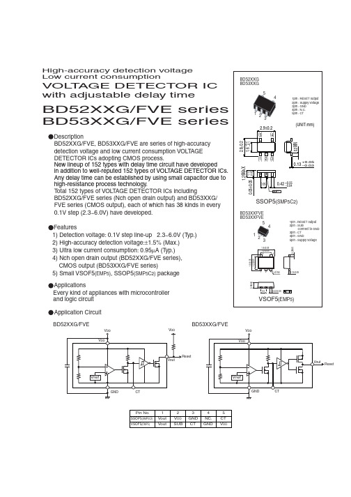
BD52XXG/FVE series BD53XXG/FVE seriesHigh-accuracy detection voltage Low current consumptionDescriptionFeaturesApplications VOL T AGE DETECTOR IC with adjustable delay timeBD52XXG/FVE, BD53XXG/FVE are series of high-accuracy detection voltage and low current consumption VOLTAGE DETECTOR ICs adopting CMOS process.New lineup of 152 types with delay time circuit have developed in addition to well-reputed 152 types of VOLTAGE DETECTOR ICs.Any delay time can be established by using small capacitor due to high-resistance process technology.Total 152 types of VOLTAGE DETECTOR ICs includingBD52XXG/FVE series (Nch open drain output) and BD53XXG/FVE series (CMOS output), each of which has 38 kinds in every 0.1V step (2.3~6.0V) have developed.1) Detection voltage: 0.1V step line-up 2.3~6.0V (Typ.)2) High-accuracy detection voltage:±1.5% (Max.)3) Ultra low current consumption: 0.95µA (Typ.)4) Nch open drain output (BD52XXG/FVE series), CMOS output (BD53XXG/FVE series)5) Small VSOF5(EMP5), SSOP5(SMP5C2) packageEvery kind of appliances with microcontroller and logic circuit BD52XXG/FVEBD53XXG/FVEPin No.SSOP5(SMP5C2)VSOF5(EMP5)Vout VoutV DD V DDGND GNDNC.CT SUBCT12345 Application CircuitAbsolute Maximum Ratings (Ta=25˚C)Characteristic diagram and Measurement circuitElectrical characteristics (Unless otherwise noted; Ta=-25~85˚C)1 ˚C ˚C *2 Derating: 2.1mW/˚C for operation above Ta=25˚C .(Mounted on a 70.0mmX70.0mmX16mm glass epoxy PCB.)*2 T PLH : V DD =(V DET typ.–0.5V) (V DET typ.+0.5V). Note) Please refer to the detection voltage of Line-up table.Output delay time "L H"Output delay time "H L"ΩV DET ΩCT Capacitance [µF]d e l a y t i m e [s ]CT Capacitance [µF]d e l a y t i m e [µs ]Part number and Marking of samplesBD5260PW PV PU PT PS PR PQ PP PN PM 6.0V 5.9V 5.8V 5.7V 5.6V 5.5V 5.4V 5.3V 5.2V 5.1V PB P A MV MU MT MS MR MQ MP MN 4.1V 4.0V 3.9V 3.8V 3.7V 3.6V 3.5V 3.4V 3.3V 3.2V RW RVRU RT RS RR RQ RN RM RP 6.0V 5.9V 5.8V 5.7V 5.6V 5.5V 5.4V 5.3V BD5241BD5259BD5258BD5257BD5256BD5255BD5254BD5253BD5252BD5251BD5240BD5239BD5238BD5237BD5236BD5235BD5234BD5233BD5232BD5360BD5359BD5358BD5357BD5356BD5355BD5354BD53535.2V 5.1V BD5352BD5351Marking VoltagePart No.Marking VoltagePart No.Marking VoltagePart No.Marking VoltagePart No.BD5341RB RA QV QU QT QS QR QQ QP QN 4.1V 4.0V 3.9V 3.8V 3.7V 3.6V 3.5V 3.4V 3.3V 3.2V BD5340BD5339BD5338BD5337BD5336BD5335BD5334BD5333BD5332BD5250PL PK PJ PH PG PF PE PD PC5.0V 4.9V 4.8V 4.7V 4.6V 4.5V 4.4V 4.3V 4.2VMM ML MK MJ MH MG MF ME MD3.1V 3.0V 2.9V 2.8V 2.7V 2.6V 2.5V 2.4V 2.3VRL RK RJRH RG RF RE RCRD 5.0V 4.9V 4.8V 4.7V 4.6V 4.5V 4.4V 4.3V BD5231BD5249BD5248BD5247BD5246BD5245BD5244BD5243BD5242BD5230BD5229BD5228BD5227BD5226BD5225BD5224BD5223BD5350BD5349BD5348BD5347BD5346BD5345BD5344BD53434.2VBD5342BD5331QM QL QK QJ QH QG QF QE QD3.1V3.0V 2.9V 2.8V 2.7V 2.6V 2.5V 2.4V 2.3VBD5330BD5329BD5328BD5327BD5326BD5325BD5324BD5323Circuit current"L" output current"H" output currentI/O characteristicBD52XXG/BD53XXG : SSOP5 (SMP5C2)BD52XXFVE/BD53XXFVE : VSOF5 (EMP5)V DS [V]I O H[m A ]Timing waveformDetection voltageV D E T VVΩV ΩV V DD [V]I D D [µA ][m A ]V DS [V]I O L V DD [V]V O U T [V ]Ta [˚C][V ]V DDV DDV OUTV 0V V OHV OLV DET +∆V DETLine-up。
序列号集锦

Name:TEAM TBE Code:6111-1516-68DC-9DCA
软件名称
完美卸载XP(Windows黄金拍档) 10.0 注册码 更新时间 2005-4-25
注册码
用户名:倪雷杰 注册码:E7574E7676B24AF3-573E0B39D58A54A0-E7574E7676B24AF3
注册码
Name: 001Warren R Smith
Key : 000016-5VDDXZ-7XPVKM-52TDCB-DX2E6F-NXEB70-YNTFM0-B KN4W6-9EF884-4GCHCN
软件名称
Broken Cross Disk Manager V3.71 注册码 更新时间 2005-4-11
注册码
Name:emporu Serial: 3XQFFG5YUAKACJYR2S8J6KFMUD0PKMY4
软件名称
Power CD to MP3 Maker V1.00 汉化版注册码 更新时间 2005-4-21
注册码
注册名:WTTI79-DH39DKJ 注册码:329745674
注册码
注册名:West King 注册码:CI2-A5A48-39284-14AD4-12036-54A1C-134422A
软件名称
Selteco Menu Maker V4.0.3 汉化注册版 更新时间 2005-4-21
注册码
s/n: 037007-110765926
软件名称
注册码
Code: 1A23-0609-9030-2380-1241-2966
软件名称
美萍VOD视频点播系统 v8.2注册码 更新时间 2005-4-20
tm52合金成份
tm52合金成份摘要:一、tm52合金简介1.tm52合金的定义2.tm52合金的成分及特点二、tm52合金的性能与应用1.力学性能2.耐腐蚀性能3.应用领域三、tm52合金的生产工艺1.熔炼与铸造2.轧制与拉伸3.热处理四、tm52合金的发展趋势与展望1.新材料的研发2.环保与可持续发展3.国内外市场前景正文:【tm52合金简介】tm52合金是一种高强度、耐腐蚀的铁基合金,主要成分包括铁、钼、铬、钴、钨等元素。
这种合金因其良好的综合性能,在许多领域得到了广泛的应用。
【tm52合金的成分及特点】tm52合金的主要成分比例为:碳(C)≤0.08%,硅(Si)≤1.00%,锰(Mn)≤1.00%,磷(P)≤0.04%,硫(S)≤0.03%,钼(Mo) 4.50-6.00%,铬(Cr) 14.00-17.00%,钴(Co) 3.00-4.00%,钨(W) 2.50-3.50%。
tm52合金具有以下特点:1.高强度:通过合适的成分设计和热处理工艺,可获得较高的屈服强度和抗拉强度;2.良好的耐腐蚀性:由于含有较高的钼、铬等元素,使得合金具有良好的耐蚀性能;3.良好的焊接性能:tm52合金可以采用各种焊接方法进行连接,易于加工。
【tm52合金的性能与应用】1.力学性能:tm52合金具有较高的屈服强度和抗拉强度,良好的韧性和疲劳性能。
这些性能使得tm52合金在许多工程应用中具有优势。
2.耐腐蚀性能:由于tm52合金中含有较高的钼、铬等元素,使其具有良好的耐腐蚀性能,特别是在还原性介质和氧化性介质中的耐蚀性表现优异。
因此,tm52合金广泛应用于化工、石油、冶金等腐蚀环境中的设备制造。
3.应用领域:tm52合金广泛应用于制造各类耐腐蚀、高强度零件,如阀门、泵、风机、压力容器、重型机械等。
【tm52合金的生产工艺】1.熔炼与铸造:tm52合金通常采用电弧炉或感应炉进行熔炼,然后采用铸造方法制成铸件。
熔炼过程中要注意控制成分和杂质含量,以确保合金的性能。
小天鹅衣炫水魔方系列洗衣机XQB70-5028HPCL技术资料
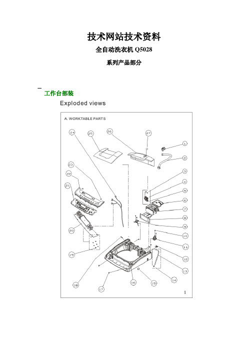
技术网站技术资料全自动洗衣机Q5028系列产品部分一、 产品爆炸图工作台部装箱体部装盛水桶部装脱水桶部装二、产品功能特点产品特点雾喷淋技术效果雾喷淋技术,使进水充分的雾化,呈雾状的喷射到高速运转脱水状态下的衣物上,极大的提高整机的洗涤、漂洗性能,节约用水量,降低能耗。
功能技术除标准、快洗、记忆、搅拌、童装、内衣、自洁、桶干燥、水循环及雾喷淋共10 种自动洗涤程序外,还可对洗涤时间、漂洗次数、脱水时间、以及洗涤、漂洗水位等过程手动调节,多种组合更多选择,做到随“衣”应变。
3.0KG以下衣物可使用搅拌洗功能。
记忆功能可按用户的洗涤习惯,自动存储用户的洗涤程序。
作到洗涤程序的因人而异,真正具有充满“人性味”的智能化程序。
自动称重精准给水,为衣物找到最合适的水搭档.洗涤更完美,省水更环保.精确称重技术能够自动判断衣服多少,给予最合适的水量,完美洗涤的同时还能达到省水效果,实现真正的智能化洗涤,让光彩展现得恰到好处。
银离子杀菌高、中、低三种除抑效果,满足衣物多元化的健康需求,功效卓越.健康内外兼施.银离子技术的杀菌和抑菌功能,带来高浓度、中浓度、低浓度三种选择,抑菌可达99%以上,银离子对人体无任何毒副作用,确保洗涤的健康,让光彩内外兼施!产品参数系列:XQB70-5028HPCL额定电源:AC220V/50Hz额定洗涤容量(kg):7.0额定脱水容量(kg) :7.0额定洗涤脱水功率(w) :450W标准尺寸(长*宽*高cm) :530×542×907.5包装尺寸(长*宽*高cm) :639×644×1030mm整机净重:36脱水桶材质:430BA不锈钢能效等级:1具体机型部分一、图片部分XQB70-5028HPCL二、安装要点部分安装与常规全自动洗衣机一致三、该产品电气接线图四、故障代码表。
LB-52资料
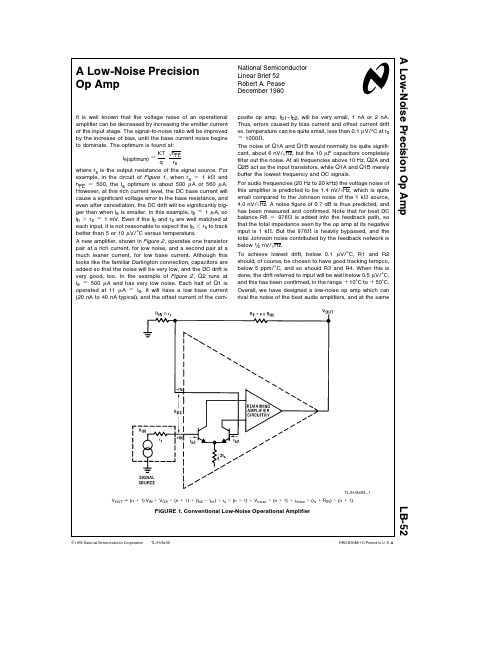
TL H 8499A Low-Noise Precision Op AmpLB-52National Semiconductor Linear Brief 52Robert A Pease December 1980A Low-Noise Precision Op AmpIt is well known that the voltage noise of an operational amplifier can be decreased by increasing the emitter current of the input stage The signal-to-noise ratio will be improved by the increase of bias until the base current noise begins to dominate The optimum is found atI e(optimum)eKT q 0h FE r swhere r s is the output resistance of the signal source For example in the circuit of Figure 1 when r s e 1k X and h FE e 500 the l e optimum is about 500m A or 560m A However at this rich current level the DC base current will cause a significant voltage error in the base resistance and even after cancellation the DC drift will be significantly big-ger than when l e is smaller In this example l b e 1m A so l b c r s e 1mV Even if the l b and r s are well matched at each input it is not reasonable to expect the l b c r s to track better than 5or 10m V C versus temperatureA new amplifier shown in Figure 2 operates one transistor pair at a rich current for low noise and a second pair at a much leaner current for low base current Although this looks like the familiar Darlington connection capacitors are added so that the noise will be very low and the DC drift is very good too In the example of Figure 2 Q2runs at l e e 500m A and has very low noise Each half of Q1is operated at 11m A e l e It will have a low base current (20nA to 40nA typical) and the offset current of the com-posite op amp I b1–l b2 will be very small 1nA or 2nA Thus errors caused by bias current and offset current drift vs temperature can be quite small less than 0 1m V C at r s e 1000XThe noise of Q1A and Q1B would normally be quite signifi-cant about 6nV 0Hz but the 10m F capacitors completely filter out the noise At all frequencies above 10Hz Q2A and Q2B act as the input transistors while Q1A and Q1B merely buffer the lowest frequency and DC signalsFor audio frequencies (20Hz to 20kHz)the voltage noise of this amplifier is predicted to be 1 4nV 0Hz which is quite small compared to the Johnson noise of the 1k X source 4 0nV 0Hz A noise figure of 0 7dB is thus predicted and has been measured and confirmed Note that for best DC balance R6e 976X is added into the feedback path so that the total impedance seen by the op amp at its negative input is 1k X But the 976X is heavily bypassed and the total Johnson noise contributed by the feedback network is below nV 0HzTo achieve lowest drift below 0 1m V C R1and R2should of course be chosen to have good tracking tempco below 5ppm C and so should R3and R4 When this is done the drift referred to input will be well below 0 5m V C and this has been confirmed in the range a 10 C to a 50 C Overall we have designed a low-noise op amp which can rival the noise of the best audio amplifiers and at the sameTL H 8499–1V OUT j (n a 1)V IN a V OS c (n a 1)a (l b2b l b1)c r s c (n a 1)a V noise c (n a 1)a i noise c (r s a R IN )c (n a 1)FIGURE 1 Conventional Low-Noise Operational AmplifierC 1995National Semiconductor Corporation RRD-B30M115 Printed in U S AL B -52A L o w -N o i s e P r e c i s i o n O p A m ptime exhibits drift characteristics of the best low-drift amplifi-ers The amplifier has been used as a precision pre-amp (gain e 1000) and also as the output amplifier for a 20-bit DAC where low drift and low noise are both important To optimize the circuit for other r s levels the emitter current for Q2should be proportional to 1 0r s The emitter current of Q1A should be about ten times the base current of Q2A The base current of the output op amp should be no more than 1 1000of the emitter current of Q2 The values of R1and R2should be the same as R7Various formulae for noiseVoltage noise of a transistor per 0Hz e n e KT2ql CCurrent noise of a transistor per 0Hz i n e2ql Ch FEVoltage noise of a resistor per 0Hz e n e 04KTR sFor a more complete analysis of low-noise amplifiers see AN-222 ‘‘Super Matched Bipolar Transistor Pair Sets New Standards for Drift and Noise’’ Carl T NelsonTracking TC k 5ppm C Solid tantalumTracking TC k 5ppm CBeckman 694-3-R100K-D or similarTL H 8499–2FIGURE 2 New Low-Noise Precision Operational Amplifier as Gain-of-1000Pre-AmpLIFE SUPPORT POLICYNATIONAL’S PRODUCTS ARE NOT AUTHORIZED FOR USE AS CRITICAL COMPONENTS IN LIFE SUPPORT DEVICES OR SYSTEMS WITHOUT THE EXPRESS WRITTEN APPROVAL OF THE PRESIDENT OF NATIONAL SEMICONDUCTOR CORPORATION As used herein 1 Life support devices or systems are devices or 2 A critical component is any component of a life systems which (a)are intended for surgical implant support device or system whose failure to perform can into the body or (b)support or sustain life and whose be reasonably expected to cause the failure of the life failure to perform when properly used in accordance support device or system or to affect its safety or with instructions for use provided in the labeling can effectivenessbe reasonably expected to result in a significant injury to the userNational Semiconductor National Semiconductor National Semiconductor National Semiconductor CorporationEuropeHong Kong LtdJapan Ltd1111West Bardin RoadFax (a 49)0-180-530858613th Floor Straight Block Tel81-043-299-2309。
HTB-52M资料

Description• For 1/4" x 1-1/4" and 5mm x 20mm fuses • All holder bodies have the option of using 1/4" x 1-1/4" or 5mm x 20mm carriers• Withstands 15 to 20 lbs-in torque to mounting nut when mounting fuseholder to panel • High temperature, flame retardant, Thermoplastic meets UL 94 VOAgency Information• UL Recognized:IZL T2, E14853• CSA Component Acceptance:Class 6225-01, File 47235FuseholdersHTB Panel Mount SeriesReplacement PartsMaximum Panel ThicknessBody TypeInch MillimetersHTB-20.307.62HTB-30.307.62HTB-40.125 3.18HTB-50.125 3.18HTB-60.307.62HTB-80.125 3.18HTB-90.1253.18SPECIFICATIONSProduct Current Voltage Fuse Quick Code Rating Rating Size Connect HTB-X2I 15A 250V 1/4" x 1-1/4"3/16"HTB-X4I 15A 250V 1/4" x 1-1/4"3/16"HTB-X6I 20A 250V 1/4" x 1-1/4"1/4"HTB-X8I 20A 250V 1/4" x 1-1/4"1/4"HTB-X2M 15A 250V 5mm x 20mm 3/16"HTB-X4M 15A 250V 5mm x 20mm 3/16"HTB-X6M 16A 250V 5mm x 20mm 1/4"HTB-X8M 16A250V5mm x 20mm 1/4"FuseholdersHTB Panel Mount SeriesVisit us on the Web at 3601 Quantum Boulevard Boynton Beach, Florida 33426-8638T el:+1-561-752-5000 T oll Free:+1-888-414-2645 Fax:+1-561-742-1178This bulletin is intended to present product design solutions and technical information that will help the end user with design applications. Cooper Electronic Technologies reserves the right, without notice, to change design or construction of any products and to discontinue or limit distribution of any products. Cooper Electronic Technologies also reserves the right to change or update, without notice, any technical information contained in this bulletin. Once a product has been selected, it should be tested by the user in all possible applications.OC-2580 5/02© Cooper Electronic Technologies 2002PACKAGING CODEPackaging CodeDescriptionBlank 10 pieces of fuseholders packed into a cartonBK100 pieces of fuseholders packed into a cardboard shelf package。
B-52轰炸机常用弹药
B-52轰炸机常用弹药
佚名
【期刊名称】《国际展望》
【年(卷),期】2001(000)021
【摘要】据新华社消息,AGM-65小牛空地导弹是一种可从敌防御火力圈外投射的武器,可精确打击点目标。
目前,美军在阿富汗动用的是AGM-65D/F/G型,采用红外成像制导,可以昼夜使用。
在海湾战争中,多国部队发射5000多枚AGM-65空地导弹,发射成功率约为80-90%。
这种导弹的单价仅7万美元,而伊拉克的T-72坦克价值150万美元,这是使用灵巧武器影响大、经济效果好的范例。
【总页数】1页(P16)
【正文语种】中文
【中图分类】D815
【相关文献】
1.B-52型同温层堡垒轰炸机
2.B-52轰炸机
3.B-52战略轰炸机
4.美空军授予波音合同研究B-52轰炸机卫星链路计划
5.美国B-52轰炸机将能够在内埋武器舱挂载JDAM智能弹药
因版权原因,仅展示原文概要,查看原文内容请购买。
新型“诺拉”B-52系列自行火炮吸引新用户

新型“诺拉”B-52系列自行火炮吸引新用户
陈来
【期刊名称】《国外坦克》
【年(卷),期】2008(000)006
【摘要】塞尔维亚Yugoimport公司现已向一个未透露的用户大量提供了其新型155毫米“诺拉”B-52系列自行轮式火炮。
【总页数】1页(P6)
【作者】陈来
【作者单位】无
【正文语种】中文
【中图分类】TJ818
【相关文献】
1.深度回顾苏联自行火炮系列之一:战争之神手里的闪电——苏联自行火炮的早期型号与生产
2.不是贵族,而是战士!——塞尔维亚/黑山诺拉B-52轮式炮内幕
3.知乎:用知识吸引新用户
4.天津公交电子票吸引百万新用户
5.深度回顾苏联自行火炮系列之二二战中的苏军自行火炮
因版权原因,仅展示原文概要,查看原文内容请购买。
- 1、下载文档前请自行甄别文档内容的完整性,平台不提供额外的编辑、内容补充、找答案等附加服务。
- 2、"仅部分预览"的文档,不可在线预览部分如存在完整性等问题,可反馈申请退款(可完整预览的文档不适用该条件!)。
- 3、如文档侵犯您的权益,请联系客服反馈,我们会尽快为您处理(人工客服工作时间:9:00-18:30)。
Description
• For 1/4" x 1-1/4" and 5mm x 20mm fuses • All holder bodies have the option of using 1/4" x 1-1/4" or 5mm x 20mm carriers
• Withstands 15 to 20 lbs-in torque to mounting nut when mounting fuseholder to panel • High temperature, flame retardant, Thermoplastic meets UL 94 VO
Agency Information
• UL Recognized:IZL T2, E14853• CSA Component Acceptance:Class 6225-01, File 47235
Fuseholders
HTB Panel Mount Series
Replacement Parts
Maximum Panel Thickness
Body Type
Inch Millimeters
HTB-20.307.62HTB-30.307.62HTB-40.125 3.18HTB-50.125 3.18HTB-60.307.62HTB-80.125 3.18HTB-9
0.125
3.18
SPECIFICATIONS
Product Current Voltage Fuse Quick Code Rating Rating Size Connect HTB-X2I 15A 250V 1/4" x 1-1/4"3/16"HTB-X4I 15A 250V 1/4" x 1-1/4"3/16"HTB-X6I 20A 250V 1/4" x 1-1/4"1/4"HTB-X8I 20A 250V 1/4" x 1-1/4"1/4"HTB-X2M 15A 250V 5mm x 20mm 3/16"HTB-X4M 15A 250V 5mm x 20mm 3/16"HTB-X6M 16A 250V 5mm x 20mm 1/4"HTB-X8M 16A
250V
5mm x 20mm 1/4"
Fuseholders
HTB Panel Mount Series
Visit us on the Web at
3601 Quantum Boulevard Boynton Beach, Florida 33426-8638
T el:+1-561-752-5000 T oll Free:+1-888-414-2645 Fax:+1-561-742-1178
This bulletin is intended to present product design solutions and technical information that will help the end user with design applications. Cooper Electronic Technologies reserves the right, without notice, to change design or construction of any products and to discontinue or limit distribution of any products. Cooper Electronic Technologies also reserves the right to change or update, without notice, any technical information contained in this bulletin. Once a product has been selected, it should be tested by the user in all possible applications.
OC-2580 5/02© Cooper Electronic Technologies 2002
PACKAGING CODE
Packaging Code
Description
Blank 10 pieces of fuseholders packed into a carton
BK
100 pieces of fuseholders packed into a cardboard shelf package。
