P4C22-35LMB中文资料
P4C22-35FM中文资料
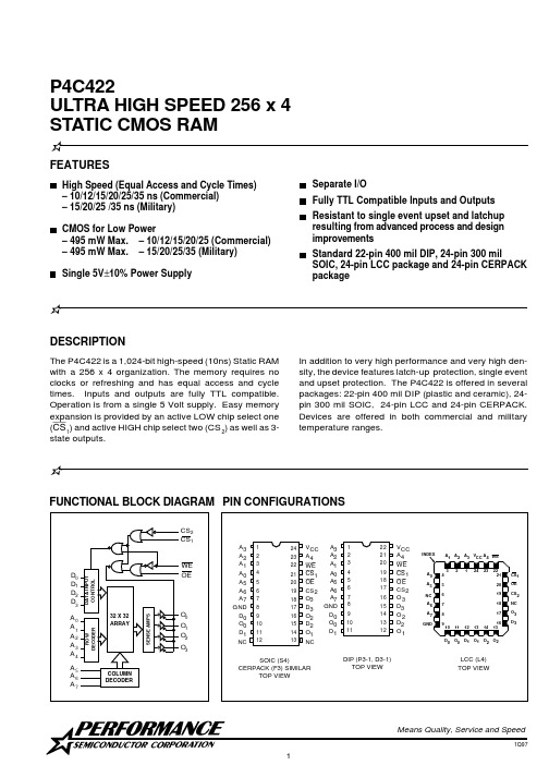
P4C422FEATURESHigh Speed (Equal Access and Cycle Times)– 10/12/15/20/25/35 ns (Commercial)– 15/20/25 /35 ns (Military)CMOS for Low Power– 495 mW Max. – 10/12/15/20/25 (Commercial)– 495 mW Max. – 15/20/25/35 (Military)DESCRIPTIONThe P4C422 is a 1,024-bit high-speed (10ns) Static RAM with a 256 x 4 organization. The memory requires no clocks or refreshing and has equal access and cycle times. Inputs and outputs are fully TTL compatible.Operation is from a single 5 Volt supply. Easy memory expansion is provided by an active LOW chip select one (CS 1) and active HIGH chip select two (CS 2) as well as 3-state outputs.P4C422ULTRA HIGH SPEED 256 x 4STATIC CMOS RAMMeans Quality, Service and Speed1Q97P4C422minimum write recovery times by eliminating the “write recovery glitch.” Reading is performed with chip selct one (CS 1) LOW, chip select two (CS 2) HIGH, write enable (WE ) HIGH and output enable (OE ) LOW. The informa-tion stored in the addressed word is read out on the noninverting outputs (O 0 through O 3). The outputs of the memory go to an inactive high impedance state whenever chip select one (CS 1) is HIGH, or during the write operation when write enable (WE ) is LOW.An active LOW write enable (WE ) controls the writing/reading operation of the memory. When the chip select one (CS 1) and the write enable (WE ) are LOW and the chip select two (CS 2) is HIGH, the information on data inputs (D 0 through D 3) is written into the addressed memory word and preconditions the output circuitry so that true data is present at the outputs when the write cycle is complete. This preconditioning operation insuresFUNCTIONAL DESCRIPTIONTRUTH TABLEAC ELECTRICAL CHARACTERISTICS—READ CYCLE(V CC = 5V ± 10% except as noted, All Temperature Ranges)(2)Mode CS 2CS 1WE OE Output Standby L X X X High Z Standby X H X X High Z D OUT Disabled H L X H High Z Read H L H L D OUT WriteHLLXHigh ZTIMING WAVEFORM OF READ CYCLENotes:H = HIGH L = LowX = Don't CareHIGH Z = Implies outputs are disabled or off. Thiscondition is defined as high impedance state for the P4C422.Sym.t RC t ACS t ZRCS t AOS t ZROS t AARead Cycle Time (5)Chip Select Time (5)Chip Select to High-Z (6)Output Enable Time Output Enable to High-Z (6)Address Access Time (5)-10*Min Max 7.587.5810-12Min 12Max 81081012-15Min 15Max 81281215-20Min 20Max 1215121520-25Min 25Max 15201520-35Min 35MaxUnit ns ns ns ns ns ns25*V CC = 5V ± 5%2530253035Parameter12P4C422AC TEST LOADS & WAVEFORMSFigure 1a Figure 1bFigure 1c Figure 1dP4C422。
贴片元件标记对应型号资料
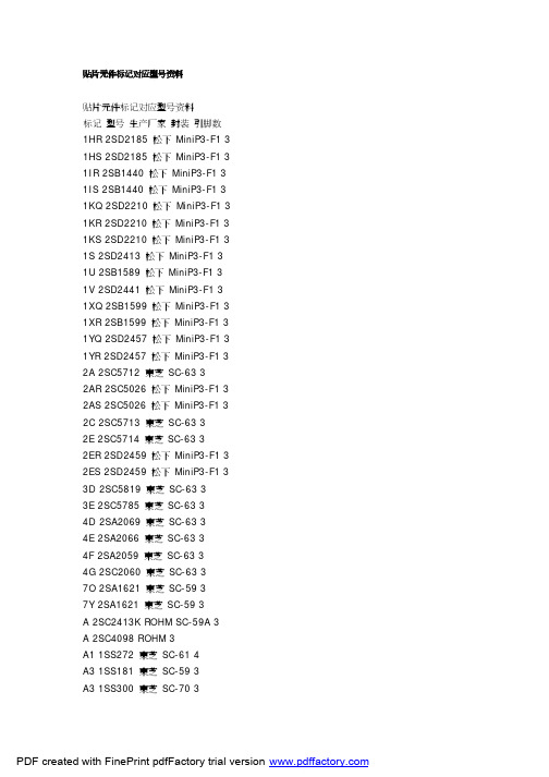
贴片元件标记对应型号资料贴片元件标记对应型号资料标记型号生产厂家封装引脚数1HR 2SD2185 松下MiniP3-F1 3 1HS 2SD2185 松下MiniP3-F1 3 1IR 2SB1440 松下MiniP3-F1 3 1IS 2SB1440 松下MiniP3-F1 3 1KQ 2SD2210 松下MiniP3-F1 3 1KR 2SD2210 松下MiniP3-F1 3 1KS 2SD2210 松下MiniP3-F1 3 1S 2SD2413 松下MiniP3-F1 3 1U 2SB1589 松下MiniP3-F1 3 1V 2SD2441 松下MiniP3-F1 3 1XQ 2SB1599 松下MiniP3-F1 3 1XR 2SB1599 松下MiniP3-F1 3 1YQ 2SD2457 松下MiniP3-F1 3 1YR 2SD2457 松下MiniP3-F1 3 2A 2SC5712 東芝SC-63 32AR 2SC5026 松下MiniP3-F1 3 2AS 2SC5026 松下MiniP3-F1 3 2C 2SC5713 東芝SC-63 32E 2SC5714 東芝SC-63 32ER 2SD2459 松下MiniP3-F1 3 2ES 2SD2459 松下MiniP3-F1 3 3D 2SC5819 東芝SC-63 33E 2SC5785 東芝SC-63 34D 2SA2069 東芝SC-63 34E 2SA2066 東芝SC-63 34F 2SA2059 東芝SC-63 34G 2SC2060 東芝SC-63 37O 2SA1621 東芝SC-59 37Y 2SA1621 東芝SC-59 3A 2SC2413K ROHM SC-59A 3 A 2SC4098 ROHM 3A1 1SS272 東芝SC-61 4A3 1SS181 東芝SC-59 3A3 1SS300 東芝SC-70 3A4 1SS319 東芝SC-61 4A4 1SS383 東芝4A5 1SS384 東芝SOT-343 4A5 1SS391 東芝SC-61 4A6 HN2S01F 東芝SC-74 6A6 HN2S01FU 東芝SC-88 6 A7 1SS402 東芝SOT-343 4A9 1SS294 東芝SC-59 3AL 2SA1971 東芝SC-63 3AL 2SC5307 東芝SC-63 3AN 2SC2532 東芝SC-59 3 AO 2SA2880 東芝SC-63 3 AQ 2SB766 松下MiniP3-F1 3 AR 2SB766 松下MiniP3-F1 3 AS 2SB766 松下MiniP3-F1 3 AU 2SB804 NEC SC-62 3AV 2SB804 NEC SC-62 3AW 2SB804 NEC SC-62 3AY 2SA2880 東芝SC-63 3B 2CS4081 ROHM 3B 2SC2412K ROHM SC-59A 3 B3 1SS184 東芝SC-59 3B3 1SS301 東芝SC-70 3B9 1SS311 東芝SC-59 3B9 1SS397 東芝SC-70 3BD 1SS271 東芝SC-59 3BE 1SV172 東芝BF 1SS268 東芝SC-59 3BG 1SS269 東芝SC-59 3BH 1SS295 東芝SC-59 3BO 2SA1200 東芝SC-63 3 BQ 2SB766A 松下MiniP3-F1 3 BR 2SB766A 松下MiniP3-F1 3 BS 2SB766A 松下MiniP3-F1 3 BU 2SD1005 NEC SC-62 3BU DA228K ROHM SC-59 3 BU DA228U ROHM SC-70 3 BV 2SD1005 NEC SC-62 3BW 2SD1005 NEC SC-62 3BY 2SA1200 東芝SC-63 3C 2SC2411K ROHM SC-59A 3C 2SC4097 ROHM 3C1 1SS352 東芝C1 1SS387 東芝C3 1SS226 東芝SC-59 3C9 1SS307 東芝SC-59 3CEO 2SC3325 東芝SC-59 3 CEY 2SC3325 東芝SC-59 3CG 2SA1163 東芝SC-59 3CK 2SD999 NEC SC-62 3CL 2SD999 NEC SC-62 3CM 2SD999 NEC SC-62 3CO 2SC2881 東芝SC-63 3CO 2SC4209 東芝SC-59 3CQ 2SB767 松下MiniP3-F1 3 CR 2SB767 松下MiniP3-F1 3 CY 2SC2881 東芝SC-63 3CY 2SC4209 東芝SC-59 3D 2SA1037KLN ROHM SC-59A 3 D3 1SS187 東芝SC-59 3DG 2SC2713 東芝SC-59 3DK 2SB798 NEC SC-62 3DL 2SB798 NEC SC-62 3DM 2SB798 NEC SC-62 3DO 2SA1201 東芝SC-63 3DQ 2SB789 松下MiniP3-F1 3 DR 2SB789 松下MiniP3-F1 3 DY 2SA1201 東芝SC-63 3E3 1SS190 東芝SC-59 3EK 2SD1001 NEC SC-62 3EL 2SD1001 NEC SC-62 3EM 2SD1001 NEC SC-62 3EO 2SC2882 東芝SC-63 3EQ 2SB789A 松下MiniP3-F1 3 ER 2SB789A 松下MiniP3-F1 3 EX 2SD2402 NEC SC-62 3EY 2SC2882 東芝SC-63 3EY 2SD2402 NEC SC-62 3EZ 2SD2402 NEC SC-62 3F 2SA1037K ROHM SC-59A 3 F 2SA1576 ROHM 3F3 1SS193 東芝SC-59 3F5 1SS250 東芝SC-59 3F5 1SS370 東芝SC-70 3F5 1SS403 東芝SOD-323 2F9 1SS321 東芝SC-59 3FK 2SB800 NEC SC-62 3FL 2SB800 NEC SC-62 3FM 2SB800 NEC SC-62 3FO 2SA1202 東芝SC-63 3FX 2SB1571 NEC SC-62 3FY 2SA1202 東芝SC-63 3FY 2SB1571 NEC SC-62 3FZ 2SB1571 NEC SC-62 3G3 1SS196 東芝SC-59 3G3 2SA1455K ROHM SC-59A 3 GK 2SD1615 NEC SC-62 3GL 2SD1615 NEC SC-62 3GM 2SD1615 NEC SC-62 3 GO 2SC2883 東芝SC-63 3 GP 2SD1615A NEC SC-62 3 GQ 2SD1615A NEC SC-62 3 GX 2SD2403 NEC SC-62 3GY 2SC2883 東芝SC-63 3GY 2SD2403 NEC SC-62 3GZ 2SD2403 NEC SC-62 3H9 1SS344 東芝SC-59 3HK 2SD1006 NEC SC-62 3HL 2SD1006 NEC SC-62 3HM 2SD1006 NEC SC-62 3 HO 2SA1203 東芝SC-63 3HP 2SD1007 NEC SC-62 3HQ 2SD1007 NEC SC-62 3HR 2SD1007 NEC SC-62 3HR 2SB956 松下MiniP3-F1 3 HS 2SB956 松下MiniP3-F1 3 HX 2SB1572 NEC SC-62 3HY 2SA1203 東芝SC-63 3HY 2SB1572 NEC SC-62 3HZ 2SB1572 NEC SC-62 3I9 1SS336 東芝SC-59 3IK 2SA1463 NEC SC-62 3IL 2SA1463 NEC SC-62 3IO 2SC3515 東芝SC-63 3IQ 2SB1073 松下MiniP3-F1 3 IR 2SC3515 東芝SC-63 3IR 2SB1073 松下MiniP3-F1 3 J 2SC2059K ROHM SC-59A 3J 2SC4099 ROHM 3J9 1SS337 東芝SC-59 3JO 2SA1384 東芝SC-63 3JR 2SK208 東芝SC-59 3JR 2SA1384 東芝SC-63 3K DA221 ROHM SC-75A 3K DA204U ROHM SC-70 3K DA204K ROHM SC-59 3K9 1SS348 東芝SC-59 3KA 2SC4409 東芝SC-63 3KD 2SC4541 東芝SC-63 3KK 2SB805 NEC SC-62 3KL 2SB805 NEC SC-62 3KM 2SB805 NEC SC-62 3KP 2SB806 NEC SC-62 3KQ 2SB806 NEC SC-62 3KR 2SB806 NEC SC-62 3L 2SC2412KLN ROHM SC-59A 3 L9 1SS349 東芝SC-59 3LA 2SA1681 東芝SC-63 3LD 2SA1736 東芝SC-63 3LK 2SD1000 NEC SC-62 3LL 2SD1000 NEC SC-62 3LM 2SD1000 NEC SC-62 3MK 2SB799 NEC SC-62 3 ML 2SB799 NEC SC-62 3 MM 2SB799 NEC SC-62 3 MO 2SC2873 東芝SC-63 3 MY 2SC2873 東芝SC-63 3 N9 1SS372 東芝SC-70 3 N9 1SS374 東芝SC-59 3 NA 2SK1273 NEC SC-62 3 NB 2SK1586 NEC SC-62 3 NC 2SK1485 NEC SC-62 3 ND 2SK1583 NEC SC-62 3 NE 2SK1585 NEC SC-62 3 NF 2SK1587 NEC SC-62 3 NG 2SK1588 NEC SC-62 3 NH 2SK1584 NEC SC-62 3 NI 2SK1586 NEC SC-62 3 NJ 2SK2111 NEC SC-62 3 NK 2SC2780 NEC SC-62 3 NL 2SC2780 NEC SC-62 3 NM 2SC2780 NEC SC-62 3 NO 2SA1213 東芝SC-63 3 NO 2SK1592 NEC SC-62 3 NP 2SK1593 NEC SC-62 3 NQ 2SK1959 NEC SC-62 3 NR 2SK1960 NEC SC-62 3 NS 2SK2109 NEC SC-62 3 NT 2SK2110 NEC SC-62 3 NV 2SK2112 NEC SC-62 3 NW 2SK2159 NEC SC-62 3 NX 2SK2857 NEC SC-62 3 NY 2SA1213 東芝SC-63 3 O9 1SS377 東芝SC-59 3 O9 1SS378 東芝SC-70 3 O9 1SS385 東芝SC-75 3 O9 1SS385F 東芝SC-81 3 OK 2SC3736 NEC SC-62 3 OL 2SC3736 NEC SC-62 3PA 2SJ179 NEC SC-62 3PB 2SJ197 NEC SC-62 3PC 2SJ199 NEC SC-62 3PD 2SJ205 NEC SC-62 3PE 2SJ207 NEC SC-62 3PF 2SJ208 NEC SC-62 3PH 2SJ206 NEC SC-62 3PO 2SC2884 東芝SC-63 3 PO 2SJ212 NEC SC-62 3PP 2SJ213 NEC SC-62 3PQ 2SJ355 NEC SC-62 3PR 2SJ356 NEC SC-62 3PY 2SC2884 東芝SC-63 3 QO 2SC2714 東芝3R12 UMR12N ROHM SC-88 6 R23 2SC3356 Q NEC SC-59 3 R24 2SC3356 R NEC SC-59 3 R25 2SC3356 S NEC SC-59 3 R9 1SS392 東芝SC-59 3R9 1SS393 東芝SC-70 3RQ 2SD1280 松下MiniP3-F1 3 RR 2SD1280 松下MiniP3-F1 3 RS 2SD1280 松下MiniP3-F1 3 S2 1SS315 東芝SC-59 3S9 1SS394 東芝SC-59 3SA 2SC2982 東芝SC-63 3SK 2SC3554 NEC SC-62 3SL 2SC3554 NEC SC-62 3SM 2SC3554 NEC SC-62 3 SO 2SA1162 東芝SC-59 3T9 1SS396 東芝SC-59 3TA 2SA1314 東芝SC-63 3TA 1SV231 東芝1-1E1A 2TB 2SA1314 東芝SC-63 3TC 2SA1314 東芝SC-63 3TE 2SD1702 NEC SC-62 3TF 2SD1702 NEC SC-62 3TL 2SC3617 NEC SC-62 3TM 2SC3617 NEC SC-62 3TQ 2SD1699 NEC SC-62 3TQ 2SD1119 松下MiniP3-F1 3 TR 2SD1699 NEC SC-62 3TR 2SD1119 松下MiniP3-F1 3 UK 2SC3618 NEC SC-62 3UL 2SC3618 NEC SC-62 3UM 2SC3618 NEC SC-62 3VK 2SD1950 NEC SC-62 3VL 2SD1950 NEC SC-62 3VM 2SD1950 NEC SC-62 3 VR 2SD968A 松下MiniP3-F1 3 VS 2SD968A 松下MiniP3-F1 3 VY 2SJ106 東芝SC-59 3W 2SD1383K ROHM SC-59A 3 W3 FMW3 ROHM 5X9 1SS398 東芝SC-59 3XK 2SD1614 NEC SC-62 3XL 2SD1614 NEC SC-62 3XM 2SD1614 NEC SC-62 3 XN 2SD1784 東芝SC-63 3 XR 2SD875 松下MiniP3-F1 3 XS 2SD875 松下MiniP3-F1 3 YB 2SK680A NEC SC-62 3YK 2SB1115 NEC SC-62 3YL 2SB1115 NEC SC-62 3YM 2SB1115 NEC SC-62 3YP 2SB1115A NEC SC-62 3 YQ 2SB1115A NEC SC-62 3 YQ 2SD874A 松下MiniP3-F1 3 YR 2SD874A 松下MiniP3-F1 3 YS 2SD874A 松下MiniP3-F1 3 Z7 2SK2549 東芝SC-63 3Z8 2SJ360 東芝SC-63 3Z9 2SJ465 東芝SC-63 3ZA 2SK2615 東芝SC-63 3ZB 2SK2963 東芝SC-63 3 ZC 2SK2964 東芝SC-63 3 ZD 2SK2992 東芝SC-63 3 ZE 2SJ508 東芝SC-63 3ZF 2SJ511 東芝SC-63 3ZG 2SK3471 東芝SC-63 3 ZK 2SB1114 NEC SC-62 3 ZL 2SB1114 NEC SC-62 3 ZM 2SB1114 NEC SC-62 3 ZO 2SA1182 東芝SC-59 3 ZQ 2SD874 松下MiniP3-F1 3 ZR 2SD874 松下MiniP3-F1 3 ZS 2SD874 松下MiniP3-F1 3 ZX 2SB1628 NEC SC-62 3 ZY 2SB1628 NEC SC-62 3 ZZ 2SB1628 NEC SC-62 3。
6MBI225U-120中文资料
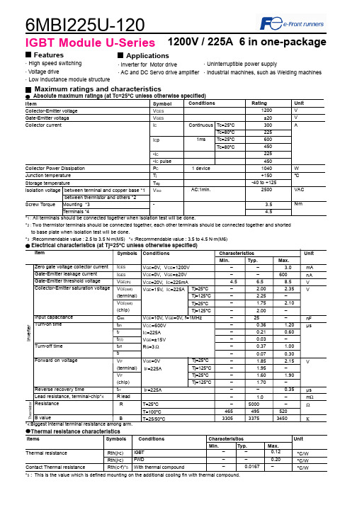
6MBI225U-1201200V / 225A 6 in one-packageFeatures· High speed switching· Voltage drive· Low inductance module structureApplications · Inverter for Motor drive· AC and DC Servo drive amplifierMaximum ratings and characteristicsThermal resistance characteristicsThermal resistanceContact Thermal resistance––0.12––0.20–0.0167 –IGBTFWDWith thermal compound°C/W°C/W°C/W*2 : Two thermistor terminals should be connected together, each other terminals should be connected together and shortedto base plate when isolation test will be done.*3 :Recommendable value : 2.5 to 3.5 N·m(M5) *4 :Recommendable value : 3.5 to 4.5 N·m(M6)Rth(j-c)Rth(j-c)Rth(c-f)*5IGBT Module U-Series*5 : This is the value which is defined mounting on the additional cooling fin with thermal compound.4Items Symbols Conditions Characteristics UnitMin.Typ. Max.· Uninterruptible power supply· Industrial machines, such as Welding machinesCharacteristics (Representative)VGE=0V, f= 1MHz, Tj= 25°CVcc=600V, I=225A, Tj= 25°CCollector current vs. Collector-Emitter voltage (typ.)Tj= 125°C / chipCapacitance vs. Collector-Emitter voltage (typ.)Dynamic Gate charge (typ.)Collector current vs. Collector-Emitter voltage (typ.)Tj= 25°C / chipCollector current vs. Collector-Emitter voltage (typ.)VGE=15V / chipTj=25°C / chipCollector-Emitter voltage vs. Gate-Emitter voltage (typ.)010020030040050060012345C o l l e c t o r c u r r e n t : I c [A ]VGE=20V15V12V10V8V010020030040050060012345C o l l e c t o r c u r r e n t : I c [A ]VGE=20V 15V12V10V8V010020030040050060001234C o l l e c t o r c u r r e n t : I c [A ]Tj=125°CTj=25°C246810510152025C o l l e c t o r - E m i t t e r v o l t a g e : V C E [ V ]Ic=450A Ic=225A Ic= 112.5A0.11.010.0100.0102030C a p a c i t a n c e : C i e s , C o e s , C r e s [ n F ]200400600800100012001400C o l l e c t o r -E m i t t e r v o l t a g e : V C E [ 200V /d i v ]G a t e - E m i t t e r v o l t a g e : V G E [ 5V /d i v]Vcc=600V, Ic=225A, VGE=±15V, Tj= 25°CStray inductance <= 100nHSwitching loss vs. Collector current (typ.)Vcc=600V, VGE=±15V, Rg=3ΩVcc=600V, Ic=225A, VGE=±15V, Tj= 125°C+VGE=15V,-VGE <= 15V, RG >= 3Ω ,Tj <= 125°CSwitching time vs. Collector current (typ.)Vcc=600V, VGE=±15V, Rg=3Ω, Tj=125°CSwitching time vs. Gate resistance (typ.)Switching time vs. Collector current (typ.)Vcc=600V, VGE=±15V, Rg=3Ω, Tj= 25°CReverse bias safe operating area (max.)Switching loss vs. Gate resistance (typ.)10100100010000100200300400S w i t c h i n g t i m e : t o n , t r , t o f f , t f [ n s e c ]Collector current : Ic [ A ]10100100010000100200300400S w i t c h i n g t i m e : t o n , t r , t o f f , t f [ n s e c ]Collector current : Ic [ A ]10100100010000110100S w i t c h i n g t i m e : t o n , t r , t o f f , t f [ n s e c ]Gate resistance : Rg [ Ω ]trtftoffton 01020304050100200300400500S w i t c h i n g l o s s : E o n , E o f f , E r r [ m J /p u l s e ]Collector current : Ic [ A ]Eon(125°C)Eon(25°C)Eoff(125°C)Err(125°C)Err(25°C)Eoff(25°C)0255075100125150110100S w i t c h i n g l o s s : E o n , E o f f , E r r [ m J /p u l s e ]Gate resistance : Rg [ Ω ]EoffErrEon0100200300400500600200400600800100012001400C o l l e c t o r c u r r e n t : I c [ A ]Collector - Emitter voltage : VCE [ V ]Transient thermal resistance (max.)Reverse recovery characteristics (typ.)Vcc=600V, VGE=±15V, Rg=3ΩForward current vs. Forward on voltage (typ.)chipTemperature characteristic (typ.)01002003004005006001234F o r w a r d c u r r e n t : I F [ A ]Forward on voltage : VF [ V ]Tj=125°CTj=25°C101001000100200300400500R e v e r s e r e c o v e r y c u r r e n t : I r r [ A ]R e v e r s e r e c o v e r y t i m e : t r r [ n s e c ]Forward current : IF [ A ]Irr (125°C)Irr (25°C)trr (125°C)trr (25°C)0.0010.0100.1001.0000.0010.0100.1001.000T h e r m a l r e s i s t a n s e : R t h (j -c ) [ °C /W ]Pulse width : Pw [ sec ]0.1110100-60-40-20020406080100120140160180Temperature [°C ]R e s i s t a n c e : R [ k Ω ]Outline Drawings, mmM6296MBI225U-120IGBT ModuleEquivalent Circuit Schematic[Thermister]135111210987246[Inverter]。
小尺寸LED电源培训资料.pptx

PE041C2/PE061C2/PE081C0电源模块介绍
上图为待机电源电路以及12V/24V过电压保护和PS_ON控制电路。 其中紫色部分为待机电源电路;灰色部分为12V/24V过电压保护电路 以及PS_ON控制电路。
PE041C2/PE061C2/PE081C0电源板待机模块
在接通市电后,待机电源部分首先工作。交流电压经整流后,水桶 电容CE1和CE2的电压约为280V左右(220V输入),其电压通过电 阻R201和R202给待机IC U201的PIN7和PIN8(DRAIN),当U201内 部的启动电路给PIN2充电到启动电压(14V)时,U201开始工作, 这时TS2的PIN 4给U201供电,同时次级输出3.3V。通过取样电阻 R213,R214与R215分压连接到U202(TL431)的1脚来控制光耦 PC2的第4脚,通过PC2的4脚来控制U201的PIN4(FB),使3.3V能稳 定输出。
PS-ON 开机信号
Condition 条件
2.0V ≤ ON ≤ 5.0V, ≥ 2mA OFF ≤ 1V
Comments 描述
Control the 12V/24Vdc output
PE041C2/PE061C2/PE081C0电源模块介绍
上图为电源的EMI滤波电路和整流滤波电路以及12V/24V主电 源部分,其中蓝色区域为EMI滤波电路和整流滤波电路;黄色部 分为12V/24V主电源电路。
输出电压
电压调整率 最小电流 额定电流 最大电流
3.3V
± 5% 5mA 0.2A 0.5A
24V
PE061C2 ± 5% 3mA 2.1A 2.5A
PE081C0 ± 5% 0.5A 2.7A 3.3A
三菱电机 第4代大型DIPIPM 应用手册
三菱电机株式会社和三菱电机机电(上海)有限公司拥有本手册内所有资料的版权。 任何个人和企业在未得到书面许可的情况下,不得传播、复制、转载、出版和出售涉及本手册的任何内 容。如有违反,我们将保留追究其法律责任的权利。敬请留意。
2009 年 3 月
第 4 代大型 DIPIPM 应用手册
目录
第 1 章 产品概要 ......................................................................................................................................... 1
2.2 保护功能及其工作时序.......................................................................................................................... 9 2.2.1 短路保护......................................................................................................................................... 9 2.2.2 控制电源欠压保护(UV) ..................................................................................................... 12 2.2.............................................................................................. 13
ZMM5235B中文资料(SynSemi)中文数据手册「EasyDatasheet - 矽搜」

16
7.8
17
600
0.1
12
ZMM5247B
17
7.4
19
600
0.1
13
ZMM5248B
18
7.0
21
600
0.1
14
ZMM5249B
19
6.6
23
600
0.1
14
ZMM5250B
20
6.2
25
600
0.1
15
ZMM5251B
22
5.6
29
600
0.1
17
ZMM5252B
24
5.2
33
600
0.1
80
800
0.1
30
ZMM5260B
43
3.0
93
900
0.1
33
ZMM5261B
47
2.7
105
1000
0.1
36
ZMM5262B
51
2.5
125
1100
0.1
39
ZMM5263B
56
2.2
150
1300
0.1
43
ZMM5264B
60
2.1
170
1400
0.1
46
ZMM5265B
62
2.0
185
1400
安装焊盘布局
0.098 (2.50) Max.
0.197 (5.00) REF
尺寸以英寸(毫米)
0.079 (2.00)Min.
最大额定值和热特性
等级25
°C环境温度,除非另有specifie.
2SC3545中文资料

1.6
1.4
1.2
1.0
0.9
0.8
0.5
REACTANCE COMPONENT
( ) ––R–– ZO
0.2
S11e
0.4
0.6
0.8
0.2 GHz
1.0
0.8 1.0
IC = 5 mA IC = 10 mA
1.8 2.0
3.0
4.0
5.0
10 20 50
0.2 GHz
S22e 1.6 GHz
10 20
2
CC.rb'b-Collector to Base Time Constant-ps
Gmax-Maximum Available Gain-dB |S21e|2-Insertion Gain-dB
Cre-Feed-back Capacitance-pF
2SC3545
TYPICAL DEVICE CAPACITANCE vs. COLLECTOR TO BASE VOLTAGE 3
元器件交易网
S-PARAMETER
S11e, S22e-FREQUENCY CONDITION VCE = 10 V, 200 MHz Step
0.6 0.8
0.7
0.404.06 0.5
0.09
0.007.413300.008.42
0.6
0.41 120
0.7
0.10 0.40
S21
114.1 92.9 81.7 70.2 62.8 54.4 47.9 40.9
S21
104.9 87.4 78.0 67.2 60.1 52.5 46.3 39.5
S12
0.037 0.055 0.077 0.098 0.108 0.125 0.148 0.160
PAM2842中文规格书

Rdown
Vdd_5V Comp
ENA
ENA
ENA
ENA
C2
R1
Vdr RT Sense+
C4
R TN
C2
R1
Vdr RT Sense+
C4
Rsense
AGND Sense-
RT
RT
AGND Sense-
Boost with low side current sense
Boost with high side current sense
方法1: 使用Rsese设定LED电流: 设定LED电流最基本的方法是连接在Rsense+和Rsense-引脚之间的电阻,计算公式如下: ILED =0.1/ Rsense 由于会流过比较大的电流,必须要考虑这个电阻的功耗状况。 Rsense 这个电阻在电路中有两种接法:高端采样和低端采样。在降压结构中只能使用高端采 样,在其它结构中可以使用高端和低端采样,这样可以方便PCB布局走线。 方法2: 使用Comp引脚接受PWM调光信号: 在下面这个电路中,Rsense用来设定常开状态时的LED电流,LED的平均电流与PWM信号低 电平的时间成正比,此时Comp引脚上是高电平。这儿使用2N7002(Q1)来隔离并反相调光信号。 (见 图-1).
Rsense Cin PAM2842 C1
HVin PGND SW
D1 L1 Rup
OV
Co
Rdown C3
R TN
ENA
ENA
Vdd_5V Comp
C2
Vdr RT
R1
Sense+ AGND Sense-
C4
RT
Buc k with high side current sense
NCP5422中文资料

Flyback, High-Voltage Power Switching Regulators with Integrated Switch
Internally Fixed Frequency PWM, without Dynamic Self Supply (DSS) Current Mode Fixed Frequency PWM with DSS NCP1000, NCP1001, NCP1002 NCP1010, NCP1011, NCP1012, NCP1013, NCP1014, NCP1027
Non-Isolated Topologies
Buck (Step Down) Boost (Step Up) Multi Topology (Step-Up, Down, or Inverting) Micro-Power, Low Voltage Buck (Step Down) Micro-Power, Low Voltage Boost (Step Up) Charge Pump Converters
Power Factor Correction Controllers
Single Stage Flyback, Continuous Conduction Mode (CCM) Boost Pre-Regulator, CCM Follower Boost Pre-Regulator, CCM Boost Pre-Regulator, Critical or Boundary Conduction Mode (BCM) Follower Boost Pre-Regulator, BCM Boost Pre-Regulator, BCM or Discontinuous Conduction Mode (DCM) Combo PFC+PWM, DCM or BCM NCP1651 NCP1650 NCP1653 MC33262, MC34262, MC33368 MC33260 NCP1601 NCP1603
柯尼卡美能达打印机维修配件及耗材技术规格及其他要求
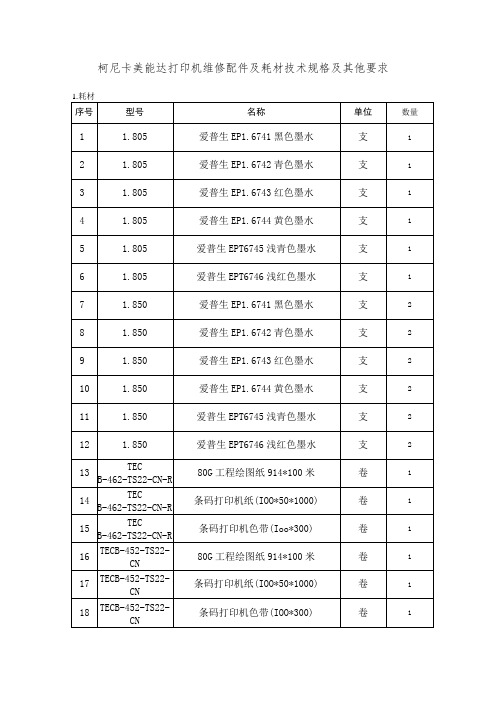
4
IOO
C221
黑色鼓组件
个
2
101
C221
鼓组件(红)
个
2
102
C221
鼓组件(黄)
个
2
103
C221
鼓组件(蓝)
个
2
104
C221
显影仓黑色
个
2
105
C221
显影仓红色
个
2
106
C221
显影仓黄色
个
2
107
C221
显影仓蓝色
个
2
108
C221
转印带
个
1
109
C221
废粉盒
个
1
no
654e
美能达原装TN712碳粉*(B654)
45
主板
1106/1136/1108/1108
套
1
46
主板维修
1106/1136/1108/1108
套
1
47
加热组件
1106/1136/1108/1108
套
1
48
激光器
1106/1136/1108/1108
套
1
49
传动组件
1106/1136/1108/1108
套
1
50
主板
1.11121E
套
1
51
主板维修
magicolor1700W
黄色粉盒
个
1
119
magicolor1700W
红色粉盒
个
1
120
magicolor1700W
蓝色粉盒
个
1
MIC23303评估板:4MHz PWM 3A 扁平电源调节器说明书
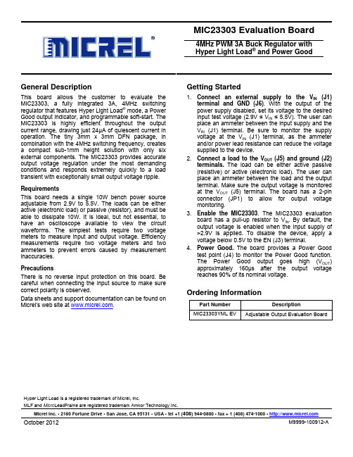
MIC23303 Evaluation Board4MHz PWM 3A Buck Regulator with Hyper Light Load ® and Power GoodHyper Light Load is a registered trademark of Micrel, Inc.MLF and Micro LeadFrame are registered trademark Amkor Technology Inc.Micrel Inc. • 2180 Fortune Drive • San Jose, CA 95131 • USA • tel +1 (408) 944-0800 • fax + 1 (408) 474-1000 • General DescriptionThis board allows the customer to evaluate the MIC23303, a fully integrated 3A, 4MHz switching regulator that features Hyper Light Load ® mode, a Power Good output indicator, and programmable soft-start. The MIC23303 is highly efficient throughout the output current range, drawing just 24µA of quiescent current in operation. The tiny 3mm x 3mm DFN package, in combination with the 4MHz switching frequency, creates a compact sub-1mm height solution with only six external components. The MIC23303 provides accurate output voltage regulation under the most demanding conditions and responds extremely quickly to a load transient with exceptionally small output voltage ripple. RequirementsThis board needs a single 10W bench power source adjustable from 2.9V to 5.5V. The loads can be either active (electronic load) or passive (resistor), and must be able to dissipate 10W. It is ideal, but not essential, to have an oscilloscope available to view the circuit waveforms. The simplest tests require two voltage meters to measure input and output voltage. Efficiency measurements require two voltage meters and two ammeters to prevent errors caused by measurement inaccuracies.PrecautionsThere is no reverse input protection on this board. Be careful when connecting the input source to make sure correct polarity is observed.Data sheets and support documentation can be found on Micrel’s web site at .Getting Started1. Connect an external supply to the V IN (J1)terminal and GND (J6). With the output of the power supply disabled, set its voltage to the desired input test voltage (2.9V ≤ V IN ≤ 5.5V). The user can place an ammeter between the input supply and the V IN (J1) terminal. Be sure to monitor the supply voltage at the V IN (J1) terminal, as the ammeter and/or power lead resistance can reduce the voltage supplied to the device.2. Connect a load to the V OUT (J5) and ground (J2)terminals. The load can be either active passive (resistive) or active (electronic load). The user can place an ammeter between the load and the output terminal. Make sure the output voltage is monitored at the V OUT (J5) terminal. The board has a 2-pin connector (JP1) to allow for output voltage monitoring.3. Enable the MIC23303. The MIC23303 evaluationboard has a pull-up resistor to V IN . By default, the output voltage is enabled when the input supply of >2.9V is applied. To disable the device, apply a voltage below 0.5V to the EN (J3) terminal.4. Power Good. The board provides a Power Goodtest point (J4) to monitor the Power Good function. The Power Good output goes high (V OUT ) approximately 160µs after the output voltage reaches 90% of its nominal voltage.Ordering InformationPart Number DescriptionMIC23303YML EVAdjustable Output Evaluation BoardEvaluation BoardOther FeaturesSoft-Start Capacitor (C2)The soft-start (SS) pin is used to control the output voltage ramp-up time. Setting C2 to 2.2nF sets the start-up time to the minimum. The start-up time can be determined by:T SS = 250x103 x ln(10) x C SSThe soft-start capacitor controls the rise time of the internal reference voltage between 0% and 100% of its nominal steady state value.Feedback Resistors (R3, R4) for Adjustable OutputThe output voltage is set nominally to 1.8V. This outputcan be changed by adjusting the upper resistor, R3, inthe feedback potential divider. Therefore:R3 = R4 x V REF/(V O-V REF)Where V REF = 0.62V.Some example values are:V OUT R3 R41.2V 274kΩ 294kΩ1.5V 316kΩ 221kΩ1.8V 560kΩ 294kΩ2.5V 324kΩ 107kΩ3.3V 464kΩ 107kΩThe feed-forward capacitor, C4, can be fitted to improve transient performance. This improves transients by injecting fast output voltage deviations directly into the feedback comparator. This improved load regulation is at the expense of slightly increasing the amount of noise on the output at higher loads. A typical value range of 22pF to 68pF is recommended.Power Good (PG)The evaluation board provides a test point above EN for testing PG. This is an open-drain connection to the output voltage with an on-board pull-up resistor of 10kΩ. This is asserted high approximately 160µs after the output voltage passes 90% of the nominal set voltage. Hyper Light Load® ModeMIC23303 uses a minimum on and off time proprietary control loop (patented by Micrel). When the output voltage falls below the regulation threshold, the error comparator begins a switching cycle that turns the PMOS on and keeps it on for the duration of the minimum-on-time. This increases the output voltage. If the output voltage is over the regulation threshold, the error comparator turns the PMOS off for a minimum-off-time until the output drops below the threshold. The NMOS acts as an ideal rectifier that conducts when the PMOS is off. Using an NMOS switch instead of a diode allows for lower voltage drop across the switching device when it is on. The asynchronous switching combination between the PMOS and the NMOS allows the control loop to work in discontinuous mode for light load operations. In discontinuous mode, the MIC23303 works in pulse frequency modulation (PFM) to regulate the output. As the output current increases, the off-time decreases, which provides more energy to the output. This switching scheme improves the efficiency of MIC23303 during light load currents by switching only when it is needed. As the load current increases, the MIC23303 goes into continuous conduction mode (CCM) and switches at a frequency centered at 4MHz. The equation to calculate the load when the MIC23303 goes into continuous conduction mode is approximated by the following formula:⎟⎟⎠⎞⎜⎜⎝⎛××−>f2LD)V(VI OUTINLOADThe previous equation shows that the load at which MIC23303 transitions from Hyper Light Load mode to PWM mode is a function of the input voltage (V IN), output voltage (V OUT), duty cycle (D), inductance (L), and frequency (f). The “Switching Frequency vs. Load” graph on page 3 shows that, as the output current increases, the switching frequency also increases until the MIC23303 goes from Hyper Light Load mode to PWM mode at approximately 300mA. The MIC23303 will switch at a relatively constant frequency around 4MHz after the output current is over 300mA.Evaluation Board Performance0.11101001000100000.00010.0010.010.1110S W F R E Q U E N C Y (k H z )LOAD CURRENT (A)Switching Frequency vs. Load CurrentV IN = 5VV IN = 3VV OUT = 1.8V1020304050607080901000.00010.0010.010.1110E F F I C I E N C Y (%)LOAD CURRENT(A)Efficiency vs. Load 1.8V OUT @25°CV IN = 3.6VV IN = 5V1020304050607080901000.00010.0010.010.1110E F F I C I E N C Y (%)LOAD CURRENT (A)Efficiency vs. Load 1.2V OUT @25°CV IN = 3.6VV IN = 3VV IN = 5V11010010001000010000010000001000100001000001000000R I S E T I M E (µs )C SS (pF)V OUT Rise Timevs. C SSV IN = 3.6V0.50.60.70.80.91.01.12.53.03.54.04.55.05.5V E N T H R E S H O L D (V )INPUT VOLTAGE (V)Enable Threshold vs. Input VoltageT CASE = 25°CMIC23303-YML Evaluation Board SchematicBill of MaterialsItem PartNumber ManufacturerDescription Qty 06036D475KAT2A AVX(1)GRM188R60J475ME19D Murata(2)C1C1608X5R0J475M TDK(3)4.7µF/6.3V, X5R, 0603 106035C222KAT2A AVXGRM188R71H222MA01D MurataC2C1608X7R1H222K TDK2.2nF/50V, X7R, 0603 108056D226MAT2A AVXGRM21BR60J226ME39L MurataC3,C8C2012X5R0J226M TDK22µF/6.3V, X5R, 0805 106035A330KAT2A AVXC4GRM1885C1H330JA01D Murata33pF/50V, 0603 1C5 ECA-1AHG221 Panasonic(4)CAP ALUM 220UF 10V 20% RADIAL 106036D105KAT2A AVXGRM188R60J105KA01D MurataC6C1608X5R0J105K TDK1µF/6.3V, X5R, 0603 106035D104KAT2A AVXGRM188R71H104KA930 MurataC7C1608X5R1H104K TDK0.1µF/6.3V, X5R, 0603 10520CDMCDSNP-R33MC Sumida(5)0.33µH/5.6A, 8mΩL1744373240033 Wurth(6)0.33µH/8.0A, 8.6mΩ1R1,R2 CRCW060310K0FKEA Vishay/Dale(7)10K, 1%, 1/10W, 0603 2R3 CRCW0603560KFKEA Vishay/Dale 560K, 1%, 1/10W, 0603 1R4 CRCW0603294KFKEA Vishay/Dale 294K,1%, 1/10W, 0603 1R5 CRCW060310R0FKEA Vishay/Dale 10Ω, 1%, 1/10W, 0603 1IC1 MIC23303-YML Micrel, Inc.(8)4MHz 3A Buck Regulator with HyperLight Load® Mode1Notes:1. AVX:.2. TDK:.3. Murata:.4. Panasonic:.5. Sumida:.6. Wurth:.7. Vishay:.8. Micrel,Inc.:.PCB Layout RecommendationsTop LayerBottom Layer。
LA系列压敏电阻

1200 to 6500
A
C C
%/OC V MΩ
CAUTION: Stresses above those listed in “Absolute Maximum Ratings” may cause permanent damage to the device. This is a stress only rating and operation of the device at these or any other conditions above those indicated in the operational sections of this specification is not implied.
Specifications (25°C) Varistor Maximum Typical Voltage at Clamping Capaci1mA Voltage tance f = DC Test 8 x 20 μs 1MHz Current V/0. V/0. IPK C VC Min Max (V) (V) (V) (A) (pF) 184 255 10 180 184 228 340 10 180 184 228 340 25 450 184 228 340 50 1000 184 228 340 100 184 220 325 100 242 360 10 160 242 360 25 400 242 360 50 242 340 100 1750 212 284 430 10 150 212 268 10 150 212 268 25 360 212 268 50 800 212 268 100 1600 212 243 360 100 1600 247 303 455 10 130 247 303 455 25 350 247 303 455 50 700 247 303 455 100 1400 324 10 100 324 25 250 324 50 550 324 100 1100 354 473 730 10 354 650 10 354 650 25 220 354 650 50 500 354 650 100 1000 354 413 620 100 1000 515 775 10 80 473 710 10 80 473 710 25 200 473 710 50 450 473 710 100 453 680 100 420 565 870 10 70 420 517 775 10 70 420 517 775 25 180 420 517 775 50 400 420 517 775 100 800 462 565 850 10 65 462 565 850 25 170 462 565 850 50 380 462 540 810 100 750 558 682 1025 10 60 558 682 1025 25 160 558 682 1025 50 360
2SC2235中文资料(toshiba)中文数据手册「EasyDatasheet - 矽搜」
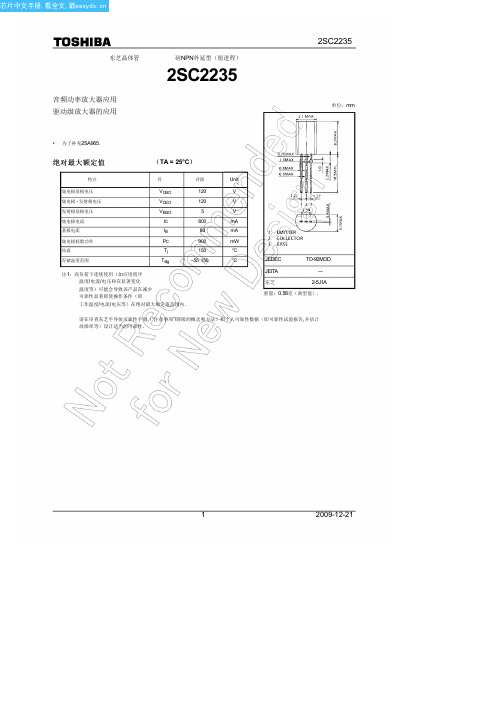
芯片中文手册,看全文,戳
东芝晶体管
音频功率放大器应用 驱动级放大器的应用
硅NPN外延型(厘进程)
2SC2235
2SC2235
单位:mm
• 为了补充2SA965.
绝对最大额定值
(TA = 25°C)
特点
符
评级
Unit
集电极基极电压
集电极 - 发射极电压
发射极基极电压 集电极电流 基极电流 集电极耗散功率 结温 存储温度范围
100 ms*
10 ms*
50
30 Collector current I
*: Single nonrepetitive 10
pulse Ta = 25°C
5 Curves must be derated
3 linearly with increase in
美芝压缩机资料

700 700 850 1000 850 1100
1200
PH260 ~PH330
650 1000
1300 1800
压缩机的使用条件
☆ 压缩机在使用时制冷剂的封入量要控制在容许范围以内,在超过上述标准 制冷剂量的场合,要追加安装分液储液器,分液储液器的容量要比下式规 定的要大: 追加分液储液器容量(cc)≥2×超过制冷剂的量(克)/1.2
46.1±0.2 ℃
吸入温度
35.0±0.2 ℃
环境温 度
35±1 ℃
排气温 度
85±5 ℃
压缩机性能与测试
● 测定方法: ☆二次冷媒热量计法(热量补偿法)作为试验X; ☆液体冷媒热量计法(冷媒焓差法)作为试验Y; 冷冻能力测试,对两个试验同时进行;主测法定为试验X。
●冷冻能力的计算:
☆试验X、Y测定值满足下式,以试验X的值作为冷冻能力;
压缩机的使用条件
二、压力
1、排气压力
☆ 压缩机排气压力规格:2.6MPa以下; ☆ 如果排气压力超过上限,可能产生下列不良:
● 轴承负荷过大…………润滑不良,运动部件磨损、粘着; ● 温度上升,过热…………绝缘材料劣化,油劣化,电机烧毁,润滑不良; ● 电流过大…………电机烧毁; ☆ 导致排气压力增大的主要原因有: ● 系统循环设计不当(冷凝器小); ● 冷媒封入量过多; ● 冷凝器通风量少,风扇停止,风扇网孔堵塞………冷凝器换热能力下降; ● 外界温度高; ● 吸入压力大或者排气管路堵塞;
压缩机性能与测试
五、热量计试验
1、试验测试项目:
压缩机冷冻能力;输入功率;COP(能效比)
2、冷冻能力测试:
☆实验设备:使用规定的热量计装置;
☆试验测定条件
2SJ352中文资料

2SJ352中⽂资料2SJ351, 2SJ352Silicon P-Channel MOS FETADE-208-1431st. EditionApplicationLow frequency power amplifierComplementary pair with 2SK2220, 2SK2221FeaturesHigh power gainExcellent frequency responseHigh speed switchingWide area of safe operationEnhancement-modeGood complementary characteristicsEquipped with gate protection diodesOrdering InformationType No.VDSX2SJ351–180 V2SJ352–200 V2SJ351, 2SJ3522OutlineAbsolute Maximum Ratings (Ta = 25°C)ItemSymbol Ratings Unit Drain to source voltage 2SJ351V DSX–180V2SJ352–200Gate to source voltage V GSS ±20V Drain currentI D –8A Body to drain diode reverse drain current I DR –8A Channel dissipation Pch*1100W Channel temperature Tch 150°C Storage temperature Tstg –55 to +150°C Note:1.Value at T C = 25°C2SJ351, 2SJ3523Electrical Characteristics (Ta = 25°C)ItemSymbol Min Typ Max Unit Test conditions Drain to source 2SJ351V (BR)DSX–180——VI D = –10 mA, V GS = 10 Vbreakdown voltage2SJ352–200——Gate to source breakdown voltageV (BR)GSS ±20——V I G = ±100 µA, V DS = 0Gate to source cutoff voltage V GS(off)–0.15—–1.45V I D = –100 mA, V DS =–10 V Drain to source saturation voltageV DS(sat)——–12V I D = –8 A, V GD = 0*1Forward transfer admittance |y fs |0.7 1.0 1.4S I D = –3 A, V DS = –10 V*1Input capacitance Ciss —800—pF V GS = 5 V, V DS = –10 V,Output capacitanceCoss —1000—pF f = 1 MHzReverse transfer capacitance Crss —18—pF Turn-on time t on —320—ns V DD = –30 V, I D = –4 A Turn-off time t off—120—nsNote:1.Pulse test2SJ351, 2SJ35242SJ351, 2SJ3526Hitachi CodeJEDECEIAJWeight (reference value)TO-3P—Conforms5.0 gUnit: mmCautions1.Hitachi neither warrants nor grants licenses of any rights of Hitachi’s or any third party’s patent,copyright, trademark, or other intellectual property rights for information contained in this document.Hitachi bears no responsibility for problems that may arise with third party’s rights, includingintellectual property rights, in connection with use of the information contained in this document.2.Products and product specifications may be subject to change without notice. Confirm that you have received the latest product standards or specifications before final design, purchase or use.3.Hitachi makes every attempt to ensure that its products are of high quality and reliability. However,contact Hitachi’s sales office before using the product in an application that demands especially high quality and reliability or where its failure or malfunction may directly threaten human life or cause risk of bodily injury, such as aerospace, aeronautics, nuclear power, combustion control, transportation,traffic, safety equipment or medical equipment for life support.4.Design your application so that the product is used within the ranges guaranteed by Hitachi particularly for maximum rating, operating supply voltage range, heat radiation characteristics, installationconditions and other characteristics. Hitachi bears no responsibility for failure or damage when used beyond the guaranteed ranges. Even within the guaranteed ranges, consider normally foreseeable failure rates or failure modes in semiconductor devices and employ systemic measures such as fail-safes, so that the equipment incorporating Hitachi product does not cause bodily injury, fire or other consequential damage due to operation of the Hitachi product.5.This product is not designed to be radiation resistant.6.No one is permitted to reproduce or duplicate, in any form, the whole or part of this document without written approval from Hitachi.7.Contact Hitachi’s sales office for any questions regarding this document or Hitachi semiconductor products.Hitachi, Ltd.Semiconductor & Integrated Circuits.Nippon Bldg., 2-6-2, Ohte-machi, Chiyoda-ku, Tokyo 100-0004, Japan Tel: Tokyo (03) 3270-2111 Fax: (03) 3270-5109 Copyright ' Hitachi, Ltd., 1999. All rights reserved. Printed in Japan.Hitachi Asia Pte. Ltd.16 Collyer Quay #20-00Hitachi TowerSingapore 049318Tel: 535-2100Fax: 535-1533URLNorthAmerica : http:/doc/bfe7be20915f804d2b16c12b.html /Europe :/doc/bfe7be20915f804d2b16c12b.html /hel/ecg Asia (Singapore):/doc/bfe7be20915f804d2b16c12b.html .sg/grp3/sicd/index.htm Asia (Taiwan):/doc/bfe7be20915f804d2b16c12b.html /E/Product/SICD_Frame.htm Asia (HongKong):/doc/bfe7be20915f804d2b16c12b.html /eng/bo/grp3/index.htm Japan :http://www.hitachi.co.jp/Sicd/indx.htmHitachi Asia Ltd.Taipei Branch Office3F, Hung Kuo Building. No.167, Tun-Hwa North Road, Taipei (105)Tel: <886> (2) 2718-3666Fax: <886> (2) 2718-8180 Hitachi Asia (Hong Kong) Ltd.Group III (Electronic Components)7/F., North Tower, World Finance Centre,Harbour City, Canton Road, Tsim Sha Tsui,Kowloon, Hong Kong Tel: <852> (2) 735 9218Fax: <852> (2) 730 0281 Telex: 40815 HITEC HXHitachi Europe Ltd.Electronic Components Group.Whitebrook ParkLower Cookham Road MaidenheadBerkshire SL6 8YA, United Kingdom Tel: <44> (1628) 585000Fax: <44> (1628) 778322Hitachi Europe GmbHElectronic components Group Dornacher Stra§e 3D-85622 Feldkirchen, Munich GermanyTel: <49> (89) 9 9180-0Fax: <49> (89) 9 29 30 00Hitachi Semiconductor (America) Inc.179 East Tasman Drive,San Jose,CA 95134 Tel: <1> (408) 433-1990Fax: <1>(408) 433-0223For further information write to:。
VIPer22A应用中文资料
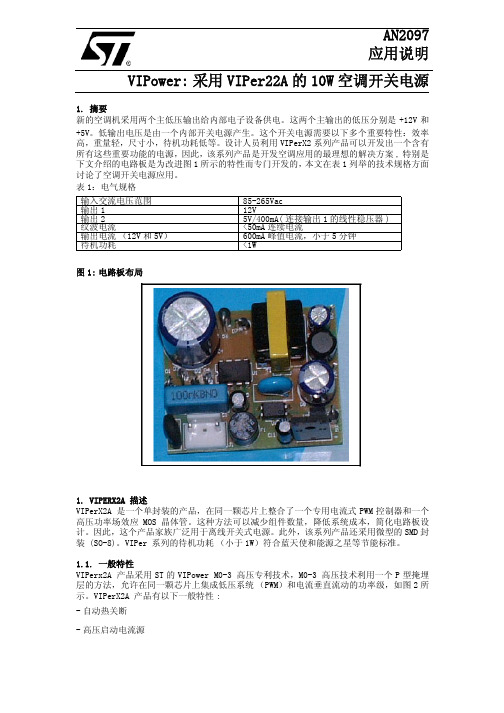
AN2097应用说明VIPower:采用VIPer22A的10W空调开关电源1. 摘要新的空调机采用两个主低压输出给内部电子设备供电。
这两个主输出的低压分别是+12V和+5V。
低输出电压是由一个内部开关电源产生。
这个开关电源需要以下多个重要特性:效率高,重量轻,尺寸小,待机功耗低等。
设计人员利用VIPerX2系列产品可以开发出一个含有所有这些重要功能的电源,因此,该系列产品是开发空调应用的最理想的解决方案,特别是下文介绍的电路板是为改进图1所示的特性而专门开发的,本文在表1列举的技术规格方面讨论了空调开关电源应用。
表1:电气规格图1:电路板布局1. VIPERX2A 描述VIPerX2A 是一个单封装的产品,在同一颗芯片上整合了一个专用电流式PWM控制器和一个高压功率场效应MOS晶体管。
这种方法可以减少组件数量,降低系统成本,简化电路板设计。
因此,这个产品家族广泛用于离线开关式电源。
此外,该系列产品还采用微型的SMD封装 (SO-8)。
VIPer 系列的待机功耗(小于1W)符合蓝天使和能源之星等节能标准。
1.1. 一般特性VIPerx2A 产品采用ST的VIPower M0-3 高压专利技术,M0-3 高压技术利用一个P型掩埋层的方法,允许在同一颗芯片上集成低压系统(PWM)和电流垂直流动的功率级,如图2所示。
VIPerX2A 产品有以下一般特性:-自动热关断-高压启动电流源输入交流电压范围85-265Vac输出112V输出25V/400mA(连接输出1的线性稳压器)纹波电流<50mA连续电流输出电流(12V和5V)600mA峰值电流,小于5分钟待机功耗<1W-防止输出短路导致击穿故障的打嗝(HICCUP)模式-保证低负载条件下低功耗的突发模式而且,VIPower M0-3技术还可用于开发最小击穿电压为730V 的功率场效应MOS 晶体管。
表2说明了该产品在不同的封装和工作条件下的功率处理能力。
PL3535B中文_Adapter_8W_20131112

1
Datasheet
PL3535B
1 概要
PL3535B是款恒流/恒压原边 制的高性能离线 反激式开关电源,仅需少数的外部元件, 内部 集成了包括 率MOSFET以及原边 制模块等 高压 率调节器
PL3535B适用于小于8W的AC/DC应用场合, 无需光耦以及 级 制电路就能实 高精度的恒 流/恒压 能 系统稳态时也无需额外的补偿电 路,从而能够得到精准的电压/电流 制
PL3535B 时 有多种保护 能 逐周期峰值电流检测 压保护 过压保护 VDD 钳 过载保护等
PL3535B
高精度恒压/恒流 原边 制 PWM 率开关
要特点:
• 内置高集成度的 率MOSFET • 为/-5%恒压调节 • 全电压范围内实 高精度电流调节 • 去除光耦和 级 制电路 • 内置高精度恒流调节的线电压补偿 • 内置变压器电感补偿 • 可编程的输 线补偿 • 内置可 高效率的自适应多模式
Hale Waihona Puke I Spk 级,并形成 级电流
I Spk = N P • I Ppk
NS
(1)
IPpk
率管关闭 的原边峰值电流
通过 级绕组和辅 绕组之间的耦合,输 电压
可以 式得到
Vo = Ns •Vaux − ∆V
Naux
(2)
Vaux
∆V
是辅 绕组的电压, 是 级 极管的压
降
9.2 软启
系统 电 ,当 VDD 达到 UVLO(OFF)主芯片开始工 作, 振荡频率及 CS 端的峰值电压会逐步增 , 因而会降 外部元件在芯片启 过程中的电压应 力 芯片每 重启都伴 着软启
率 MOSFET MOSFET 漏源 穿电压 导通电阻
VDD =16V主 TA = 25℃
贴片P系列三极管参数

SOT23 SOT23 SOT23 SOT23 SOT23 SOT23 SOT23 SOT23 SOT23 SOT23 SOT23 SOT23 SOT23 SOT23 SOT23 SOT23 SOT23 SOD323 SOT23 SOT23 SOT323 SOT23 SOT323 SOT23 SOT323
SGS Sil Sil SGS Sil Sil Sil Sil Sil Sil Sil Sil Sil Sil Sil Mot Mot Sil Sil Sil Phi Sie Sie Sie Sie Sie Sie Sie
N F F F F F F F F F F F F F M M F F F I C D D B B A A
P33 P38 P39 P39 P40 P41 P57 P58 P59 P60 P61 P62 P63 P64 P65 PC PD PH2 PH3 PH4 PL POs PPs PPs PRs PRs PSs PSs
SO5401 SST4338 SST4339 SO692 SST4340 SST4341 SST5457 SST5458 SST5459 SST5460 SST5461 SST5462 SST5463 SST5464 SST5465 MGSF1P02L BSS84L SST4302 SST4303 SST4304 BB149A BAR64 BAR64-04 BAR64-04W BAR64-05 BAR64-05W BAR64-06 BAR64-06W
Manufactur er Sie Tok Roh Phi Tem HP HP SGS Sil Sil SGS Sil Sil SGS SGS Phi Tem Mot Mot Mot Phi Mot Mot Phi Phi HP HP Mot Mot Mot Mot Tem Phi Phi Zet HP Phi Zet Phi Mot SGS SGS SGS SGS
富士宝IH-P250电磁炉原理

富士宝IH-P250电磁炉原理根据测绘,富士宝IH-P250电磁炉的主板电路如图所示。
电路由一块LM339比较器加一块CPU处理器构成,元件较少。
主要有下面几个部分组成:1、主电源部分:AC220V 50HZ电压经保险FUSE,再通过压敏电阻R2、电流互感器CT的初级、C21电容滤波,送至整流块BD,再由L1、C22滤波后产生振荡所需的电源。
2、辅助电源部分:AC220V 50HZ电压接入变压器初级线圈,次级两绕组分别产生AC 18V和AC 14V电压。
AC 18V电压经二极管D13整流、C15滤波后,再通过由Q4、R27、ZD2、C16、C17、C28组成的串联型稳压滤波电路,产生+18V电压给LM339比较器及IGBT激励电路使用。
AC 14V电压经二极管D4-D7桥式整流后,一路经R28给散热风扇提供电源,另一路经过7805稳压、C13、C14、C25滤波后输出+5V电压,给CPU及相关电路供电。
3、同步电路:TER2通过R44、R43、R4分压,加到UD的11脚(同相输入端);TER1通过R42、R2分压,加到UD的10脚(反向输入端),当电磁炉刚接通电源,处于待机状态时,UD的11脚(同相输入端)高于10脚(反向输入端),UD13脚通过R5输出高电位。
使UA的4脚(反向输入端)电位高于5脚(同相输入端),UA 2脚输出低电位,IGBT截止。
开机后,CPU 3脚输出的振荡脉冲通过C8加到UD的10脚(反向输入端),使UD的11脚(同相输入端)低于10脚(反向输入端),UD13脚输出低电位,并通过C3耦合到UA的4脚(反向输入端),使UA的4脚(反向输入端)电位低于5脚(同相输入端),UA 2脚输出高电位,IGBT导通。
4、PWM脉宽调控电路:CPU 10脚输出的PWM脉冲经过R10、C6、R11积分电路后,一路经R12送到Q3的基极,控制UA 5脚(同相输入端)的电位,PWM脉冲宽度越宽,Q3截止的时间越长,UA 5脚(同相输入端)处于高电位的时间就越长,IGBT导通的时间就越长,加热的功率就越大。
P4LED显示屏-P4LED显示屏技术-P4LED单元板元器件作用

室内P4LED显示屏详细技术指标P4LED显示屏详细技术参数:一、管芯参数的说明:序号名称管芯型号波长亮度数量芯片大小1红管光磊管芯630±2nm710mcd1颗12 mil2纯绿管仕兰管芯525±2nm1900mcd1颗14 mil3纯蓝管仕兰管芯470±2nm380mcd1颗14 mil4封装方式DIP 5465水平视角≥120º6垂直视角≥120º7显示颜色256*256*256=16777216色8备注为使配色达到最佳的白平衡效果,选择正波波长的管芯,配色对LED 发光的亮度有严格要求,其中各种颜色亮度的配色比例为: R:G:B/3:6:1,无马赛克现像出现二、像素点结构图像素分辩率:62500点/平方米结构说明:每像素点采用1红1纯绿1纯蓝3颗LED发光管。
三、单元板及模组参数序号名称参数1单元板/模组规格PH4点阵屏2单元板/模组尺寸256mm * 128mm3模组分辨率64点* 32点 = 2048点四、箱体规格参数序号名称参数1 箱体规格PH4点阵屏2 箱体尺寸768 mm(宽)×512 mm(高)3 模块数量4张(宽)× 6张(高)= 24 块4 箱体分辨率256点× 192点 = 49152点5 箱体后门规格双开门6 是否有风扇箱体内部带有风扇7 箱体电源/信号接口内串线结构8 是否防水否五、每块全彩色屏体显示部分设计序号项目HH-O4-3C1 最佳观看距离8米~ 300米2 显示屏亮度≥1800 CD/㎡3 屏幕水平可视视角≥120°4 屏幕垂直视角≥120°5 存贮温度-40℃~ +85℃6 工作温度-25℃~ +65℃7 相对湿度10%~95%RH8 屏体重量65kg/㎡9 包装方式纸箱+木框+珍珠棉10 工作电压380V±10%11 平均功耗400 ~ 600 W/m212 最大功耗1000W/ m213 驱动方式静态恒流14 刷新频率≥420Hz15 换帧频率≥120Hz16 失控率1/10000 一年后的失控点为2-3/1000017 灰度/颜色逻辑输出16384级,CRT视觉256级灰度,颜色:16777216色六、显示屏技术参数18 图像调节白平衡/对比度/视觉修正/色度调节/单模组调亮度19 亮度调节方式软件100级可调,根据不同环境亮度自动或手动调节显示亮度20 视频信号RF、S-Video、RGB、AV、等21 视频信号源有线电视、DVD、VCD、PC、RGBHV、YUV、YC、COMPOSITE、VIDEO22 播放方式视频、动画、文字信息等交替使用或任意组合23 信号处理能力不低于10bit24 计算机显示模式1024×768;1280×768;800×60025 图像切换VGA同步同帧26 反γ校正曲线具备三条以上可调节的γ曲线27 控制系统采用PCTV卡+DVI显卡+主控卡+光纤传输(可选)28 平均无故障时间≥10000小时29 屏体寿命≥100,000小时 (10万小时)30 连续工作时间≥72小时31 平整度任意相邻像素间≤0.5mm;模组拼接间隙<1mm32 均匀性像素光强、模组亮度均匀33 盲点率<0.0001(像元失效率/呈离散状态)34 电气防护过流、短路、断路、过压防护35 外部防护防水、防潮、防尘、防风雪、防高温(散热)、防腐、阻燃36 电阻:防雷接地电阻<10Ω工作接地电阻<4Ω37 有效通讯距离多模光纤500m内,单模光纤20km内(可用网络线)38 抗盐雾能力符合GB/T 2423.17-93、GB2424.10七、控制系统39 控制主机联想开天主机或同档次计算机以上40 操作系统WIN 98/ 2000/ XP41 控制方式与计算机同步42 显卡DVI显卡43 软件LED演播室1 范围本标准规定了LED显示屏的定义、分类、技术要求、检验方法、检验规则以及标志包装运输贮存要求。
- 1、下载文档前请自行甄别文档内容的完整性,平台不提供额外的编辑、内容补充、找答案等附加服务。
- 2、"仅部分预览"的文档,不可在线预览部分如存在完整性等问题,可反馈申请退款(可完整预览的文档不适用该条件!)。
- 3、如文档侵犯您的权益,请联系客服反馈,我们会尽快为您处理(人工客服工作时间:9:00-18:30)。
P4C422
FEATURES
High Speed (Equal Access and Cycle Times)– 10/12/15/20/25/35 ns (Commercial)
– 15/20/25 /35 ns (Military)
CMOS for Low Power
– 495 mW Max. – 10/12/15/20/25 (Commercial)– 495 mW Max. – 15/20/25/35 (Military)
DESCRIPTION
The P4C422 is a 1,024-bit high-speed (10ns) Static RAM with a 256 x 4 organization. The memory requires no clocks or refreshing and has equal access and cycle times. Inputs and outputs are fully TTL compatible.Operation is from a single 5 Volt supply. Easy memory expansion is provided by an active LOW chip select one (CS 1) and active HIGH chip select two (CS 2) as well as 3-state outputs.
P4C422
ULTRA HIGH SPEED 256 x 4STATIC CMOS RAM
Means Quality, Service and Speed
1Q97
P4C422
minimum write recovery times by eliminating the “write recovery glitch.” Reading is performed with chip selct one (CS 1) LOW, chip select two (CS 2) HIGH, write enable (WE ) HIGH and output enable (OE ) LOW. The informa-tion stored in the addressed word is read out on the noninverting outputs (O 0 through O 3). The outputs of the memory go to an inactive high impedance state whenever chip select one (CS 1) is HIGH, or during the write operation when write enable (WE ) is LOW.
An active LOW write enable (WE ) controls the writing/reading operation of the memory. When the chip select one (CS 1) and the write enable (WE ) are LOW and the chip select two (CS 2) is HIGH, the information on data inputs (D 0 through D 3) is written into the addressed memory word and preconditions the output circuitry so that true data is present at the outputs when the write cycle is complete. This preconditioning operation insures
FUNCTIONAL DESCRIPTION
TRUTH TABLE
AC ELECTRICAL CHARACTERISTICS—READ CYCLE
(V CC = 5V ± 10% except as noted, All Temperature Ranges)(2)
Mode CS 2CS 1WE OE Output Standby L X X X High Z Standby X H X X High Z D OUT Disabled H L X H High Z Read H L H L D OUT Write
H
L
L
X
High Z
TIMING WAVEFORM OF READ CYCLE
Notes:
H = HIGH L = Low
X = Don't Care
HIGH Z = Implies outputs are disabled or off. This
condition is defined as high impedance state for the P4C422.
Sym.t RC t ACS t ZRCS t AOS t ZROS t AA
Read Cycle Time (5)Chip Select Time (5)Chip Select to High-Z (6)Output Enable Time Output Enable to High-Z (6)Address Access Time (5)
-10*Min Max 7.587.5810
-12Min 12
Max 81081012
-15Min 15
Max 81281215
-20Min 20
Max 1215121520
-25Min 25
Max 15201520-35
Min 35
Max
Unit ns ns ns ns ns ns
25
*V CC = 5V ± 5%
2530253035
Parameter
12
P4C422
AC TEST LOADS & WAVEFORMS
Figure 1a Figure 1b
Figure 1c Figure 1d
P4C422。
