M5M5V108DFP-70H中文资料
介绍M580
● 支持X80 I/O系列模块, 这些模块基于M340控制器并且在全世界已经有大量的 应用
● 嵌入了以太网 Remote I/O (RIO) 主干 ● 使用了来自意法半导体(ST Microelectronics)的最新一代双核ARM处理器,可
以提供强大的复杂运算,网络通讯,图形显示和控制应用能力 ● 全新的以太网背板,提供了更强大的扩展性和灵活性:
分布式I/O(DIO)
对任何设备开放
Modbus TCP 或 EIP 设备
=S= 的设备有更好的集成
DTM 支持 STB, ATV, Tesys T, Power Meters…
刷新频率可配置 开放的架构
环, 星形, 网….
需作网格配置
交换机冗余协议等…
用于其他协议的外部网关
12
远程子站适配器- BME CRA 312 10
● 与背板的双连接:
● X-Bus (1) ● 以太网 (2)
M580 Configuration V1.0 Schneider Electric | Industry Business | Training | March 9, 2020
● 适配孔可以防止模块安装在BMX的老 机架上 (3)
M580 Configuration V1.0
Schneider Electric | Industry Business | Training | March 9, 2020
11
远程子站适配器- BME CRA 312 10
● 为了利用新的M580 以太网背板, M580架构中提供了新的远程子站适配 器模块:
M580 Configuration V1.0
Schneider Electric | Industry Business | Training | March 9, 2020
喷头型号及参数信息1

项目 打印宽度 墨滴大小 点火频率
参数 72.17mm 7/14/21/28/35pl 单点 30khz
项目 有效喷孔 物理精度 适应墨水
参数 512*2列 360DPI 溶剂、UV墨水以及水性墨水
• 喷头内有恒温装置和电路保湿系统,不易受环境影响
• 支持单喷头,双色。
项目 打印宽度 墨滴大小点火频率 适用机型 Nhomakorabea参数
项目
54mm
有效喷孔
7/14/21/28/35pl 物理精度
单点 30khz 3级灰 适应墨水 度17khz
5300R,R2000, TS2000
参数 320*4列 300DPI 溶剂、UV墨水以及水性墨水
• 3、理光GH2220喷头
• 理光GH2220:优点:精度高、喷头和机器售价都较为低廉。 缺点是容易堵头喷头容易报废、兼容性差、打印效率低、故 障率高。
项目 打印宽度 墨滴大小
点火频率
参数
项目
32.4mm
有效喷孔
3~21pl
物理精度
单点 30khz 3级灰 适应墨水 度17khz
参数 384 300DPI 溶剂、UV墨水以及水性墨水
三、Epson-DX5
最小墨点为3.5PL相对其它的喷头打印精细度最高。 单头支持4色或8色输出,使用成本低廉。 兼容性较好,墨水适用广泛 使用寿命在12个月左右
项目 打印宽度 墨滴大小
点火频率 适用机型
参数 25.4mm 3.5pl—27pl 17Khz R180,X2,X3,X4
北京人民GM8系列塑壳断路器(电气和机械为20000和8000次)

GM8-400H/3Zs SHT+AX TIs In=400A 含义:GM8系列断路器,壳架等级额定电流400A,分断能力等级为50kA,3极,带智能本体控制器,
装备辅助开关和分励脱扣器,并选配了脱扣指示模块,额定电流400A。
北京人民电器厂有限公司 6
第一章 GM8系列概览
1
操作方式 无 本体 Z 手操 P 电操
I
北京人民电器厂有限公司 9
1
第一章 GM8系列概览
4、智能式脱扣器(配电保护) GM8-Zn 额定电流范围:16~800A
脱扣方式
脱扣器代号
保护功能
过载长延时保护(智能)
(可调)
短路短延时保护(智能)
(可调)
智能式脱扣器 (本体式)
配电保护:Zn 矿用断路器:ZUn
短路瞬时保护(智能) (可调)
第一章 GM8系列概览
1
6种可选脱扣器
1、热电磁式脱扣器 GM8-TM 额定电流范围:10~800A
脱扣方式
脱扣器代号
保护功能
热电磁式脱扣器
配电保护:TM、M 变压器保护:TMB 发电机保护:TMF 电动机保护:TMD、MD 矿用断路器:TMU
过载长延时保护(热动) (内置固定)
短路瞬时保护(电磁) (内置固定)
4ֵ̖КጆѴ˝ᆀᮺऺ NJNJŁ ̨ၸ̅GM8-Zsఄᑞறᡸ٧ NJNJł Dž ᛪᇧథҩᑞὋú ᛪᇧҩᑞ
Ń AὙڙᆀᡸௐ̠˝ᆀढௐὋBὙڙᆀᡸௐథ̠˝ᆀढௐnj
ӑ̠̚ඞႂ٧ԇథᬌМՂ
4
ኃʶብ GM8ጆѴഏ
1
GM8-400
400
250Ὃ315Ὃ350Ὃ400
400200~400Ὀ
NC7SZ08P5X,NC7SZ08M5X,NC7SZ08FHX, 规格书,Datasheet 资料
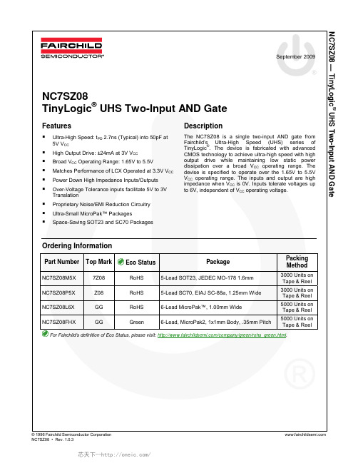
®TinyLogic UHS Two-Input AND GateFeaturesUltra-High Speed: t PD 2.7ns (Typical) into 50pF at 5V V CCHigh Output Drive: ±24mA at 3V V CCBroad V CC Operating Range: 1.65V to 5.5VMatches Performance of LCX Operated at 3.3V V CC Power Down High Impedance Inputs/OutputsOver-Voltage Tolerance inputs facilitate 5V to 3V TranslationProprietary Noise/EMI Reduction CircuitryUltra-Small MicroPak™ PackagesSpace-Saving SOT23 and SC70 Packages DescriptionThe NC7SZ08 is a single two-input AND gate from Fairchild’s Ultra-High Speed (UHS) series of TinyLogic®. The device is fabricated with advanced CMOS technology to achieve ultra-high speed with high output drive while maintaining low static power dissipation over a broad V CC operating range. The devise is specified to operate over the 1.65V to 5.5V V CC operating range. The inputs and output are high impedance when V CC is 0V. Inputs tolerate voltages up to 6V, independent of V CC operating voltage.Ordering InformationPart Number Top Mark Eco Status Package Packing MethodNC7SZ08M5X 7Z08 RoHS 5-Lead SOT23, JEDEC MO-178 1.6mm 3000 Units on Tape & ReelNC7SZ08P5X Z08 RoHS 5-Lead SC70, EIAJ SC-88a, 1.25mm Wide 3000 Units on Tape & ReelNC7SZ08L6X GG RoHS 6-Lead MicroPak™, 1.00mm Wide 5000 Units on Tape & ReelNC7SZ08FHX GG Green 6-Lead,MicroPak2, 1x1mm Body, .35mm Pitch 5000 Units on Tape & ReelFor Fairchild’s definition of Eco Status, please visit: /company/green/rohs_green.html.NC7SZ08 — TinyLogic ® UHS Two-Input AND GateFigure 1. Logic SymbolPin ConfigurationsFigure 2. SC70 and SOT23 (Top View)Figure 3. MicroPak (Top Through View)Pin DefinitionsPin # SC70 / SOT23Pin # MicroPakNameDescription1 1 A Input2 2 B Input3 3 GND Ground4 4 Y Output56 V CC Supply Voltage5 NC No ConnectFunction TableY=ABInputs OutputNC7SZ08 — TinyLogic ® UHS Two-Input AND GateSymbol Parameter Min. Max. UnitV CC Supply Voltage -0.5 6.0 V V IN DC Input Voltage -0.5 6.0 V V OUT DC Output Voltage -0.56.0 V V IN < -0.5V -50 I IK DC Input Diode Current V IN > 6.0V +20 mAV OUT < -0.5V-50I OK DC Output Diode Current V OUT > 6V, V CC =GND+20 mAI OUT DC Output Current±50 mA I CC or I GND DC V CC or Ground Current±50 mA T STG Storage Temperature Range -65 +150 °C T J Junction Temperature Under Bias+150 °C T LJunction Lead Temperature (Soldering, 10 Seconds)+260°CSOT-23 200SC70-5 150MicroPak-6 130 P DPower Dissipation at +85°CMicroPak2-6 120mWHuman Body Model, JESD22-A114 4000 ESD Charged Device Model, JESD22-C1012000VRecommended Operating ConditionsThe Recommended Operating Conditions table defines the conditions for actual device operation. Recommendedoperating conditions are specified to ensure optimal performance to the datasheet specifications. Fairchild does not recommend exceeding them or designing to Absolute Maximum Ratings.Symbol ParameterConditions Min. Max. UnitSupply Voltage Operating 1.65 5.50 V CCSupply Voltage Data Retention1.50 5.50 V V IN Input Voltage 0 5.5VV OUT Output Voltage0 V CC V T A Operating Temperature-40 +85 °C V CC at 1.8V, 2.5V ± 0.2V 0 20® UHS Two-Input AND Gate1.65 1.55 1.65 1.55 1.80 1.70 1.80 1.702.30 2.20 2.30 2.203.00 2.90 3.00 2.904.50V IN =V IH , I OH =-100µA 4.40 4.504.401.65 I OH =-4mA 1.29 1.52 1.292.30 I OH =-8mA 1.90 2.15 1.903.00 I OH =-16mA 2.50 2.80 2.40 3.00 I OH =-24mA 2.40 2.68 2.30VV OHHIGH LevelOutput Voltage4.50 I OH =-32mA 3.90 4.20 3.801.65 0.00 0.10 0.10 1.80 0.00 0.10 0.102.30 0.00 0.10 0.103.00 0.00 0.10 0.104.50V IN =V IL , I OL =100µA 0.00 0.10 0.10 1.65 I OL =4mA 0.80 0.24 0.24 2.30 I OL =8mA 0.10 0.30 0.30 3.00 I OL =16mA 0.15 0.40 0.40 3.00 I OL =24mA 0.22 0.55 0.55 VV OLLOW LevelOutput Voltage4.50 I OL =32mA0.22 0.55 0.55 I IN Input LeakageCurrent0 to 5.5V IN =5.5V, GND±1±10µAI OFF Power OffLeakage Current0 V IN or V OUT =5.5V 1 10 µAI CCQuiescent SupplyCurrent1.65 to 5.50 V IN =5.5V, GND220µA® UHS Two-Input AND Gate5.00 ± 0.500.5 2.2 4.1 0.5 4.4 3.30 ± 0.30 1.53.3 5.2 1.5 5.55.00 ± 0.50 C L =50pF,R L =500Ω0.8 2.7 4.5 0.84.8C IN Input Capacitance 0.00 4 pF 3.30 20 C PDPower DissipationCapacitance (2)5.0025pF Figure 6Note:2. C PD is defined as the value of the internal equivalent capacitance which is derived from dynamic operatingcurrent consumption (I CCD ) at no output lading and operating at 50% duty cycle. C PD is related to I CCD dynamic operating current by the expression: I CCD =(C PD )(V CC )(f IN )+(I CC static).Notes:3. C L includes load and stray capacitance.4. Input PRR=1.0MHz; t W 500ns.Figure 4. AC Test CircuitFigure 5. AC Waveforms=1.8ns; PRR=10MHz; Duty Cycle=50%.Test Circuit® UHS Two-Input AND Gate132LAND PATTERN RECOMMENDATIONC 0.10C0.20C A B0.60 REF0.550.35SEATING PLANE0.25GAGE PLANE8°0°NOTES: UNLESS OTHEWISE SPECIFIEDA) THIS PACKAGE CONFORMS TO JEDEC MO-178, ISSUE B, VARIATION AA,B) ALL DIMENSIONS ARE IN MILLIMETERS. 1.45 MAX1.300.900.150.051.900.950.500.301.502.600.701.00SEE DETAIL A0.220.08C) MA05Brev5TOP VIEW (0.30)Figure 7. 5-Lead SOT23, JEDEC MO-178 1.6mmPackage drawings are provided as a service to customers considering Fairchild components. Drawings may change in any manner without notice. Please note the revision and/or date on the drawing and contact a Fairchild Semiconductor representative to verify or obtain the most recent revision. Package specifications do not expand the terms of Fairchild’s worldwide terms and conditions, specifically the warranty therein, which covers Fairchild products.Always visit Fairchild Semiconductor’s online packaging area for the most recent package drawings: /packaging/.Tape and Reel Specifications®UHS Two-Input AND GateFigure 8. 5-Lead, SC70, EIAJ SC-88a, 1.25mm WidePackage drawings are provided as a service to customers considering Fairchild components. Drawings may change in any mannerwithout notice. Please note the revision and/or date on the drawing and contact a Fairchild Semiconductor representative to verifyor obtain the most recent revision. Package specifications do not expand the terms of Fairchild’s worldwide terms and conditions, specificallythe warranty therein, which covers Fairchild products.Always visit Fairchild Semiconductor’s online packaging area for the most recent package drawings:/packaging/.Tape and Reel Specifications® UHS Two-Input AND Gate2. DIMENSIONS ARE IN MILLIMETERS1. CONFORMS TO JEDEC STANDARD M0-252 VARIATION UAAD MAC06AREVCNotes:3. DRAWING CONFORMS TO ASME Y14.5M-1994TOP VIEWRECOMMENED LAND PATTERNBOTTOM VIEWA0.55MAX0.05C(0.75)(0.52)(0.30)6X 1X6X PIN 1DETAIL A0.075 X 45CHAMFER0.250.150.350.250.400.300.5(0.05) 1.0DETAIL APIN 1 TERMINAL0.400.300.450.350.100.000.10C B A 0.05CC0.05C0.050.005X 5X 6X(0.13)4X6XFigure 9. 6-Lead, MicroPak™, 1.0mm WidePackage drawings are provided as a service to customers considering Fairchild components. Drawings may change in any manner without notice. Please note the revision and/or date on the drawing and contact a Fairchild Semiconductor representative to verify or obtain the most recent revision. Package specifications do not expand the terms of Fairchild’s worldwide terms and conditions, specifically the warranty therein, which covers Fairchild products.Always visit Fairchild Semiconductor’s online packaging area for the most recent package drawings: /packaging/.®UHS Two-Input AND Gate DETAIL A5XFigure 10. 6-Lead, MicroPak2, 1x1mm Body, .35mm PitchPackage drawings are provided as a service to customers considering Fairchild components. Drawings may change in any mannerwithout notice. Please note the revision and/or date on the drawing and contact a Fairchild Semiconductor representative to verifyor obtain the most recent revision. Package specifications do not expand the terms of Fairchild’s worldwide terms and conditions, specificallythe warranty therein, which covers Fairchild products.Always visit Fairchild Semiconductor’s online packaging area for the most recent package drawings:/packaging/.NC7SZ08 — TinyLogic ® UHS Two-Input AND Gate。
灵畅H型互动一体机规格书
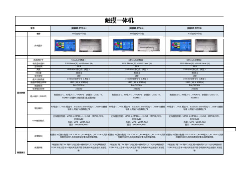
灵畅FIT-TVI55H灵畅FIT-TVI65H灵畅FIT-TVI70H 名称55寸互动一体机65寸互动一体机70寸互动一体机外观图片液晶屏尺寸55inch(对角线)64.5inch(对角线)69.5inch(对角线)有效显示面积1209.6mm(W) x 680.4mm (H)1428.48mm(W) x 803.52mm (H)1538.88mm(W) x 865.62mm (H)显示比例16:916:916:9亮度400cd/㎡(中心点、典型)360cd/㎡(中心点、典型)350cd/㎡(中心点、典型)对比度4000:14000:14000:1背光类型LED LED LED最大可视角度178°(V)/178°(H) (典型)178°(V)/178°(H) (典型)178°(V)/178°(H) (典型)液晶屏物理分辨率1920(H) X 1080(V)1920(H) X 1080(V)1920(H) X 1080(V)视频制式PAL/SECAM PAL/SECAM PAL/SECAM伴音输出功率2X10W2X10W2X10W输入端口(1080P)高频接口*1,AV输入*1,YPbPr*1,多媒体(USB)*2,HDMI*4(内置PC1路,前置1路,后置2路)高频接口*1,AV输入*1,YPbPr*1,多媒体(USB)*2,HDMI*3高频接口*1,AV输入*1,YPbPr*1,多媒体(USB)*2,HDMI*3输出端口AV输出*1,VGA 输出*1,AUDIO(3.5mm耳机)*1,USB*1(触摸专用),同轴*1,音频输出*1AV输出*1,VGA 输出*1,AUDIO(3.5mm耳机)*1,USB*1(触摸专用),同轴*1,音频输出*1AV输出*1,VGA 输出*1,AUDIO(3.5mm耳机)*1,USB*1(触摸专用),同轴*1,音频输出*1USB播放格式支持播放视频:MPEG-2.MPEG-4,H.264,MJPEG,RV8,RV9.RV10音频:MP3,WMA,AAC图片:JPG,BMP,PNG支持播放视频:MPEG-2.MPEG-4,H.264,MJPEG,RV8,RV9.RV10音频:MP3,WMA,AAC图片:JPG,BMP,PNG支持播放视频:MPEG-2.MPEG-4,H.264,MJPEG,RV8,RV9.RV10音频:MP3,WMA,AAC图片:JPG,BMP,PNG前置接口前置向下式接口包括USB TOUCH*1,HDMI输入*1,PC USB*1,支持前置接口接入后的信源及触摸自动切换功能.前置向下式接口包括USB TOUCH*1,HDMI输入*1,PC USB*1,支持前置接口接入后的信源及触摸自动切换功能.前置向下式接口包括USB TOUCH*1,HDMI输入*1,PC USB*1,支持前置接口接入后的信源及触摸自动切换功能.前置按键8键按键(7键TV+1键PC),可实现一键开关PC及TV,及可单独开关TV,PC开机状态下一键开关背光节能.总电源开关位于整机下部边缘.8键按键(7键TV+1键PC),可实现一键开关PC及TV,及可单独开关TV,PC开机状态下一键开关背光节能.总电源开关位于整机下部边缘.8键按键(7键TV+1键PC),可实现一键开关PC及TV,及可单独开关TV,PC开机状态下一键开关背光节能.总电源开关位于整机下部边缘.触摸一体机型号显示参数前置接口整机特色产品特色资源库资源库嵌入式PCOPS工业模块MINI ATX 模块主板H61H61OPS功能CPU:G2010、i3、i5、i7CPU:G2010、i3、i5、i7内存2G/4G 2G/4G 硬盘500G500G 操作系统Windows7操作系统Windows7操作系统显卡集成集成声卡集成集成无线键盘/鼠标选配选配接口HDMI,USB,VGA,音频,RJ-45网络接口HDMI,USB,VGA,音频,RJ-45网络接口其他整机功耗≤160W≤270W ≤250W 待机功耗≤0.5W≤0.5W ≤0.5W 整机寿命50000小时50000小时50000小时电源要求100-240V, 50/60Hz100-240V, 50/60Hz 100-240V, 50/60Hz 壁挂架有有有移动支架选配选配选配整机尺寸1296X730X81mm1550X944X109mm 1626X979X112mm 整机重量55Kg75Kg 72Kg 包装尺寸1425x210x950mm1760X1180X290mm 1850X1230X290mm 包装重量70Kg 90Kg 87Kg 其它参数嵌入式PC 1、整机采用触摸和TV一体式前壳设计,双色拉丝铝合金表面处理,设置了前置指示与感应器,向下式前置按键及输入输出接口.2、后壳采用PVC 吸塑材料,模具制造.整机超薄.3、采用前拆式可维护触摸屏结构,可在不取下整机前提下进行触摸屏的维修.触摸屏支持假两点,真两点,四点及更多点数.4、PC采用OPS工业模块或MINI ATX两种架构同时兼容.采用标准OPS接口与其它设备连接,内部走线,整个PC无任何外部接线.5、采用模块化PC结构,可手动从整机下部拆下维护.6、采用内凹式散热区设计,可防止灰尘进入机器内部.整机顶部与底部的散热孔对流,提供良好的散热通道.ATX PC主机外置于机器,不会对机内产品多余热量.7、采用圆边设计,提供安全保护.底部采用向内倾斜的设计,不会对操作带来不便.8、前置向下式 HDMI TOUCHUSB PC USB,方便自带PC时使用.自动识别前置接口信号接入,自动切换.前置黑板感应器,当有物体阻挡时会自动关闭屏幕,节能环保.9、PC一键开关PC及TV. TV一键开关TV节能更环保.可内置顶部USB接口,便于外接摄像头.10、书写流畅度较以往所有产品都高.支持1,2,4点触摸 操作,支持WIN8操作.待机功率低于0.5W.11、自行研发的专业教育软件.拟物化的标图设计.操作简单,使用方便.12、多点书写与手势识别.自定义手势功能.多语言支持.提供500G资源库正面图背部图注:机型不同会略有不同,以实物为准.。
烽火设备基础资料

780BNMU单盘硬件
面板指示灯含义
指示灯 ACT
UA/NUA NET SBUS MBUS
DCC指示灯
指示灯状态
备注
长亮但不闪烁表示 NMU盘未得到正确的配置 或时间;正常工作时,均 匀闪烁。
★ MBS1 MBUS1口通讯状态指示.闪动表示该口收到数据,本设备对外有6个MBUS1
口并联使用,可将其它功能模块(框、架)纳入到本设备进行管理
★ MBS2 MBUS2口通讯状态指示 闪动表示该口收到数据
★ DCCw 西DCC接收指示
闪动表示该口收到数据
★ DCCe 东DCC接收指示
闪动表示该口收到数据
6 6 611 3 3 322
EEEEEE 111111 ︱︱︱︱︱︱
666666 333333
123
456789
00 01 02 03 04 05 06 0 0 09 0 0 0 0 0 0F
11
78
ABCDE
风扇及分纤单元
OO
TTAAO 0
OO
25 25
U U U U 15 15
25 25
00 00
★ SBUS BCT应答指示 均匀闪动表示BCT与EMU通讯正常,不闪动表示
EMU未收到BCT应答,闪动频度不均匀表示可能有BCT通讯不好
★ NET F口数据指示灯 该灯以一定的频率闪动表示F口有数据收发
★ DCC0~3 从CPU串行口1~4指示灯 闪动表示该口收到数据
GF155-03BEMU单盘说明
❖ 可对某站点的光/电分支设备进行管理,;
M5M51008DVP中文资料

Regarding the change of names mentioned in the document, such as Mitsubishi Electric and Mitsubishi XX, to Renesas Technology Corp.The semiconductor operations of Hitachi and Mitsubishi Electric were transferred to Renesas Technology Corporation on April 1st 2003. These operations include microcomputer, logic, analog and discrete devices, and memory chips other than DRAMs (flash memory, SRAMs etc.) Accordingly, although Mitsubishi Electric, Mitsubishi Electric Corporation, Mitsubishi Semiconductors, and other Mitsubishi brand names are mentioned in the document, these names have in fact all been changed to Renesas Technology Corp. Thank you for your understanding. Except for our corporate trademark, logo and corporate statement, no changes whatsoever have been made to the contents of the document, and these changes do not constitute any alteration to the contents of the document itself.Note : Mitsubishi Electric will continue the business operations of high frequency & optical devices and power devices.Renesas Technology Corp.Customer Support Dept.April 1, 2003To all our customers元器件交易网1048576-BIT(131072-WORD BY8-BIT)CMOS STATIC RAMDESCRIPTIONFEATURESThe M5M51008DP,FP,VP,RV,KV are a 1048576-bit CMOS static RAM organized as 131072 word by 8-bit which are fabricated using high-performance quadruple-polysilicon and double metal CMOS technology. The use of thin film transistor (TFT) load cells and CMOS periphery result in a high density and low power static RAM.They are low standby current and low operation current and ideal for the battery back-up application.The M5M51008DVP,RV,KV are packaged in a 32-pin thin small outline package which is a high reliability and high density surface mount device(SMD). Two types of devices are available. M5M51008DVP(normal lead bend type package),M5M51008DRV(reverse lead bend type package).Using both types of devices, it becomes very easy to design a printed circuit board.PackageAPPLICATIONSmall capacity memory unitsDirectly TTL compatible : All inputs and outputsEasy memory expansion and power down by S1,S2Data hold on +2V power supplyCommon data I/O1048576-BIT(131072-WORD BY 8-BIT)CMOS STATIC RAMFUNCTIONThe operation mode of the M5M51008D series are determined by a combination of the device control inputs S 1,S 2,W and OE.Each mode is summarized in the function table.A write cycle is executed whenever the low level W overlaps with the low level S 1and the high level S 2. The address must be set up before the write cycle and must be stable during the entire cycle.The data is latched into a cell on the trailing edge of W,S 1or S 2,whichever occurs first,requiring the set-up and hold time relative to these edge to be maintained. The output enable input OE directly controls the output stage. Setting the OE at a high level,the output stage is in a high-impedance state, and the data bus contention problem in the write cycle is eliminated.A read cycle is executed by setting W at a high level and OE at a low level while S 1and S 2are in an active state(S 1=L,S 2=H).When setting S 1at a high level or S 2at a low level, the chip are in a non-selectable mode in which both reading and writing are disabled. In this mode, the output stage is in a high- impedance state, allowing OR-tie with other chips and memory expansion by S 1and S 2. The power supply current is reduced as low as the stand-by current which is specified as I CC3or I CC4, and the memory data can be held at +2V power supply, enabling battery back-up operation during power failure or power-down operation in the non-selected mode.FUNCTION TABLENote 1: "H" and "L" in this table mean VIH and VIL, respectively.2: "X" in this table should be "H" or "L".1048576-BIT(131072-WORD BY 8-BIT)CMOS STATIC RAMABSOLUTE MAXIMUM RATINGSCAPACITANCE Symbol ParameterTest conditionspF pFUnit Max 10TypMinLimits Input capacitance Output capacitanceC I C OParameterSupply voltage Input voltage Output voltage Power dissipationOperating temperature Storage temperatureUnit V V V mW °C °CConditionsWith respect to GND Ta=25°C7000~70– 65~150Ratings Symbol V cc V I V O P d T opr T stgDC ELECTRICAL CHARACTERISTICS (Ta=0~70°C, Vcc=5V±10%, unless otherwise noted)Symbol ParameterV V V MaxTypLimits Min Test conditionsUnit V µA – 0.3*~7– 0.3*~Vcc + 0.3(Ta=0~70°C, Vcc=5V±10% unless otherwise noted)0~Vcc * –3.0V in case of AC ( Pulse width ≤ 50ns )Note 3: Direction for current flowing into an IC is positive (no mark).4: Typical value is Vcc = 5V, Ta = 25°CmA* –3.0V in case of AC ( Pulse width ≤ 50ns )µAµAmAVVcc + 0.30.82.2–0.3*2.43Stand-by current0.4±1Active supply current (AC, MOS level)Active supply current (AC, TTL level)Vcc – 0.5±180V IH V IL V OH V OL I I I OI CC1I CC2I CC3I CC4High-level input voltage Low-level input voltage High-level output voltage Low-level output voltage Input currentOutput current in off-state Stand-by current I OH = –1.0mA I OH = –0.1mA I OL =2mA V I =0~VccS 1=V IH or S 2=V IL or OE=V IH V I/O =0~V CCS 1=V IL ,S 2=V IH ,other inputs=V IH or V IL Output-open(duty 100%)1) S 2≤ 0.2V,other inputs=0~V CC 2) S 1≥ V CC –0.2V,S 2 ≥ V CC –0.2V,other inputs=0~V CC S 1=V IH or S 2=V IL ,other inputs=0~V CC~25°C ~40°C ~70°C-H2620mA151MHz S 1≤ 0.2V, S 2≥ VCC–0.2Vother inputs ≤ 0.2V or ≥ VCC–0.2V Output-open(duty 100%)851570ns 55ns 70701MHz 70ns 55ns V O =GND,V O =25mVrms, f=1MHzFP,VP,RV,KVFP,VP,RV,KV V I =GND, V I =25mVrms, f=1MHz 845343739421048576-BIT(131072-WORD BY 8-BIT)CMOS STATIC RAM(2)READ CYCLE(3)WRITE CYCLESymbol Parametert CR Read cycle timeAddress access timeUnit ns ns ns ns ns ns ns ns ns ns ns nsSymbol ParameterUnit ns ns ns ns ns ns ns ns ns ns ns ns nsLimitst a(S1)t a(S2)t a(OE)t dis(S1)t dis(S2)t dis(OE)t en(S1)t en(S2)t en(OE)t V(A)t a(A)LimitsAC ELECTRICAL CHARACTERISTICS (Ta=0~70°C, 5V±10% unless otherwise noted ) (1)MEASUREMENT CONDITIONSChip select 1 access time Chip select 2 access time Output enable access time Output disable time after S 1high Output disable time after S 2low Output disable time after OE high Output enable time after S 1low Output enable time after S 2high Output enable time after OE low Data valid time after address70707035252525701010510Write cycle time Write pulse width Address setup timeAddress setup time with respect to W Chip select 1 setup time Chip select 2 setup time Data setup time Data hold timeWrite recovery timeOutput disable time from W low Output disable time from OE high Output enable time from W high Output enable time from OE low252570500555555300055Input pulse level V IH =2.4V,V IL =0.6V (-70H)V IH =3.0V,V IL =0.0V (-55H) Input rise and fall time 5ns Reference level V OH =V OL =1.5VOutput loads Fig.1, C L =100pF (-70H)C L =30pF (-55H)C L =5pF (for t en ,t dis )Transition is measured ± 500mV from steady state voltage. (for t en ,t dis )..........................................................Fig.1 Output loadMin Max -70HMax Min t CW t w(W)t su(A)t su(A-WH)t su(S1)t su(S2)t su(D)t h(D)t rec(W)t dis(W)t dis(OE)t en(W)t en(OE)-70H L ( Including scopeand JIG )1.8k ΩV CCDQ202055450505050250055Max Min -55H 55555530202020555555Min Max -55H1048576-BIT(131072-WORD BY 8-BIT)CMOS STATIC RAMRead cycleWrite (W (4)TIMINGDIAGRAMS DQ 1~8S 1S 2OEWA 0~16DQ 1~8S 1S 2OEA 0~161048576-BIT(131072-WORD BY 8-BIT)CMOS STATIC RAMWrite cycle (S 1control mode)Write cycle (S 2control mode)DQ 1~8S 1S 2WA 0~16DQ 1~8S 1S 2WA 0~16Note 5: Hatching indicates the state is "don't care".6: Writing is executed while S 2high overlaps S 1and W low.7: When the falling edge of W is simultaneously or prior to the falling edge of S 1or rising edge of S 2, the outputs are maintained in the high impedance state.8: Don't apply inverted phase signal externally when DQ pin is output mode.1048576-BIT(131072-WORD BY 8-BIT)CMOS STATIC RAMV CC = 3V1) S 2 ≤ 0.2V, other inputs = 0~3V 2) S 1 ≥ V CC –0.2V,S 2 ≥ V CC –0.2V other inputs = 0~3V(Ta=0~70°C, unless otherwise noted)S 2≤ 0.2V(3)POWER DOWN CHARACTERISTICS S 1control modeS 2control modePOWER DOWN CHARACTERISTICS(1)ELECTRICAL CHARACTERISTICS Power down set up time Power down recovery time(2)TIMING REQUIREMENTS (Ta=0~70°C, unless otherwise noted )t su (PD)t rec (PD)Symbol Parameterns MaxTypLimits Min Test conditionsUnit 05msV CCS 1V CCS 2Symbol ParameterV VMaxTypLimits Min Test conditionsUnit µA0.2V CC (PD)V I (S1)V I (S2)I CC (PD)Power down supply voltage Chip select input S 1Chip select input S 2Power down supply current2.2~25°C ~40°C~70°C-H 1310V0.8Vcc(PD)4.5V ≤Vcc(PD)Vcc(PD)<4.5V 2.2V ≤Vcc(PD) 2.02V ≤Vcc(PD)≤2.2V Note 9: On the power down mode by controlling S 1,the input level of S 2 must be S 2 ≥Vcc - 0.2V orS 2 ≤ 0.2V. The other pins(Address,I/O,WE,OE) can be in high impedance state.Keep safety first in your circuit designs!Mitsubishi Electric Corporation puts the maximum effort into making semiconductor products better and more reliable, but there is always the possibility that trouble may occur with them. Trouble with semiconductors may lead to personal injury, fire or property damage. Remember to give due consideration to safety when making your circuit designs, with appropriate measures such as (i) placement of substitutive, auxiliary circuits, (ii) use of non-flammable material or (iii) prevention against any malfunction or mishap.Notes regarding these materialsThese materials are intended as a reference to assist our customers in the selection of the Mitsubishi semiconductor product best suited to the customer's application; they do not convey any license under any intellectual property rights, or any other rights, belonging to Mitsubishi Electric Corporation or a third party.Mitsubishi Electric Corporation assumes no responsibility for any damage, or infringement of any third-party's rights, originating in the use of any product data, diagrams, charts, programs, algorithms, or circuit application examples contained in these materials.All information contained in these materials, including product data, diagrams, charts, programs and algorithms represents information on products at the time of publication of these materials, and are subject to change by Mitsubishi Electric Corporation without notice due to product improvements or other reasons. It is therefore recommended that customers contact Mitsubishi Electric Corporation or an authorized Mitsubishi Semiconductor product distributor for the latest product information before purchasing a product listed herein.The information described here may contain technical inaccuracies or typographical errors. Mitsubishi Electric Corporation assumes no responsibility for any damage, liability, or other loss rising from these inaccuracies or errors.Please also pay attention to information published by Mitsubishi Electric Corporation by various means, including the Mitsubishi Semiconductor home page ().When using any or all of the information contained in these materials, including product data, diagrams, charts, programs, and algorithms, please be sure to evaluate all information as a total system before making a final decision on the applicability of the information and products. Mitsubishi Electric Corporation assumes no responsibility for any damage, liability or other loss resulting from the information contained herein.Mitsubishi Electric Corporation semiconductors are not designed or manufactured for use in a device or system that is used under circumstances in which human life is potentially at stake. Please contact Mitsubishi Electric Corporation or an authorized Mitsubishi Semiconductor product distributor when considering the use of a product contained herein for any specific purposes, such as apparatus or systems for transportation, vehicular, medical, aerospace, nuclear, or undersea repeater use.The prior written approval of Mitsubishi Electric Corporation is necessary to reprint or reproduce in whole or in part these materials.If these products or technologies are subject to the Japanese export control restrictions, they must be exported under a license from the Japanese government and cannot be imported into a country other than the approved destination.Any diversion or reexport contrary to the export control laws and regulations of Japan and/or the country of destination is prohibited.Please contact Mitsubishi Electric Corporation or an authorized Mitsubishi Semiconductor product distributor for further details on these materials or the products contained therein.。
DNH扬声器

DNH扬声器HS-8EExmNT
DNH扬声器HS-15EExmNT
DNH室内壁挂扬声器 CP-6T
DNH室内壁挂扬声器 SAFE-10PT
DNH室内壁挂扬声器 DSP-25
DNH扬声器DSP-25EEXMNT
DNH扬声器SAFE-3 PT
DNH扬声器HS-25EExmN(T)
HP-30, 8 Ohm, 30W, Polyamide, RAL 7035, IP-67, Stahlbügel
HP-30, 20 Ohm, 30W, Polyamide, RAL 7035, IP-67, Kunststoffbügel
HP-30, 20 Ohm, 30W, Polyamide, RAL 7035, IP-67, Stahlbügel
APPLETON阿普顿ACP3034BC
APPLETON阿普顿NCP20232
APPLETON加热棒
APPLETON防爆插头ACP1034CD 100A 3W4P
APPLETON防爆插座AP20044E 200A 4W4P
APPLETON防爆插头ADR20044 200A
APPLETON阿普顿AR20034
DSP-15L, 25W, 8 Ohm, ASA, RAL -7035, IP-67 mit Kunststoffbügel
DSP-15L, 25W, 8 Ohm, ASA, RAL -7035, IP-67 mit Stahlbügel
DSP-15T L, 25W, 70/100 Volt, ASA, RAL -7035, IP-67 mit Kunststoffbügel
H-44, 8 Ohm,MP-2,5, 6 W, IP 67, RAL 7035
五舟科技服务器产品说明书

S627H4WUZHOU TECHNOLOGY CO.,LTD.本手册的用途在于帮助您正确地使用五舟科技公司服务器产品(以下称“本产品”),在安装和第一次使用本产品前,请您务必先仔细阅读随机配送的所有资料,特别是本手册中所提及的注意事项。
这会有助于您更好和安全地使用本产品。
请妥善保管本手册,以便日后参阅。
本手册的描述并不代表对本产品规格和软硬件配置的任何说明。
有关本产品的实际规格和配置,请查阅相关协议、装箱单、产品规格配置描述文件,或向产品的销售商咨询。
如您不正确地或未按本手册的指示和要求安装、使用或保管本产品,或让非五舟科技公司授权的技术人员修理、变更本产品,五舟科技公司将不对由此导致的损害承担任何责任。
本手册中所提供照片、图形、图表和插图,仅用于解释和说明目的,可能与实际产品有些差别,另外,产品实际规格和配置可能会根据需要不时变更,因此与本手册内容有所不同。
请以实际产品为准。
本手册不用于表明五舟科技公司对其产品和服务做了任何保证,无论是明示的还是默示的,包括(但不限于)本手册中推荐使用产品的适用性、安全性、适销性和适合某特定用途的保证。
对本产品及相关服务的保证和保修承诺,应按可适用的协议或产品标准保修服务条款和条件执行。
在法律法规的最大允许范围内,五舟科技公司对于您的使用或不能使用本产品而发生的任何损害(包括,但不限于直接或间接的个人损害、商业利润的损失、业务中断、商业信息的遗失或任何其他损失),不负任何赔偿责任。
对于您在本产品之外使用本产品随机提供的软件,或在本产品上使用非随机软件或经五舟科技公司认证推荐使用的专用软件之外的其他软件,五舟科技公司对其可靠性不做任何保证。
五舟科技公司已经对本手册进行了仔细的校勘和核对,但不能保证本手册完全没有任何错误和疏漏。
为更好地提供服务,五舟科技公司可能会对本手册中描述的产品软件和硬件及本手册的内容随时进行改进或更改,恕不另行通知。
如果您在使用过程中发现本产品的实际情况与本手册有不一致之处,或您想得到最新的信息或有任何问题和想法,欢迎致电400-898-1286。
人民电器 高压电器选型手册 说明书

People ElectricHV Electrical Equipment Selection Guide 高压选型手册人民电器集团是人民控股集团全资公司,中国500强企业之一,始创于1986年。
人民电器集团以工业电器为核心产业,拥有浙江、上海、南昌、抚州、枣庄、合肥六大制造基地、35家全资子公司150家控股成员企业、1500多家加工协作企业和5000多家销售公司。
产品畅销全球125个国家和地区,广泛应用于浦东机场、京沪高铁、三峡水电、北京地铁、奥运场馆南水北调、青藏铁路、嫦娥探月工程、越南太安水电枢纽等国内外重大工程项目,位居世界机械企业500强前列。
2023年,经世界品牌实验室测评,品牌价值788.15亿。
户内高压真空断路器ZN28口-12户内高压交流真空断路器RDV6-12户内高压交流真空断路器ZN73-12(VS1)户内高压交流真空断路器ZN73S-12户内固封式高压交流真空断路器ZN73S-24户内高压交流真空断路器ZN85-40.5户内高压交流真空断路器ZN85S-40.5户内高压交流真空断路器074 079 084 089 091 093 095Contents智能电网自动化开关ZW8-12C户外高压交流自动重合断路器ZW8F-12户外高压交流分界真空断路器ZW20F-12户外高压交流分界真空断路器ZW32F-12户外高压交流分界真空断路器ZW20A-12C户外高压交流自动重合断路器ZW32-12C户外高压交流自动重合断路器ZW32(B)-12C户外高压交流自动重合断路器ZW32-24C户外高压交流自动重合断路器FZW28-12F户外分界负荷开关001 005 009 012 016 020 024 027 030智能电网永磁式真空断路器ZW8M-12户外永磁式高压真空断路器ZW32M-12户外永磁式高压真空断路器ZN73M-12户内永磁式高压真空断路器034 038 041智能电网预付费自动化设备ZW8-12(YZD)户外高压预付费控制断路器ZW32-12(YZD)户外高压预付费控制断路器045 049户外高压真空断路器ZW8-12户外高压交流真空断路器ZW20A-12户外高压交流真空断路器ZW32-12户外高压交流真空断路器ZW32(B)-12户外高压交流真空断路器ZW32-24户外高压交流真空断路器ZW7-40.5户外高压交流真空断路器ZW7A-40.5户外高压交流真空断路器053 057 060 063 066 068 071户内(外)高压交流负荷开关FN12-12户内高压交流负荷开关FNR12-12户内高压负荷开关一熔断器组合电器FZN25A-12D户内高压交流真空负荷开关FZRN25A-12D户内高压交流真空负荷开关一熔断器组合电器FZW32-12户外高压交流真空隔离负荷开关FZW32-40.5户外高压交流真空隔离负荷开关097 097 101 101 106 109其它高压电器GW4-12户外高压交流隔离开关GW9-12户外高压隔离开关GW4-40.5户外高压交流隔离开关GW5-40.5户外高压交流隔离开关GN19-12户内高压交流隔离开关GN19-12M户内高压隔离开关GN22-12户内高压隔离开关GN24-12D户内高压隔离开关GN30-12户内高压隔离开关GN30-12M户内高压隔离开关JSXGN-12机械闭锁RW10-12F户外高压交流跌落式熔断器RW11-12户外高压交流跌落式熔断器RW-12户外高压交流跌落式熔断器RW-24户外高压交流跌落式熔断器PRWG2-40.5户外高压交流跌落式熔断器RW5-40.5户外高压交流跌落式熔断器JN15-12户外高压交流接地开关JN22B-40.5户内高压交流接地开关CT19弹簧操动机构CT19B弹簧操动机构YH氧化锌避雷器3-10kV带脱离器复合外套金属氧化避雷器户外交流高压跌落式(可投式、可卸式)避雷器三相组合式金属氧化物避雷器(TBP)放电计数器在线检监测仪LA(J)-10Q穿墙式浇注绝缘电流互感器LZZBJ9-10C1、2、5支柱式全封闭浇注绝缘电流互感器LZZBJ9-10A、A1G、A2G支柱式全封闭浇注绝缘电流互感器JDZ-10(Q)单相半封闭全绝缘浇注电压互感器JDZ10-10(A、B)单相全封闭全绝缘浇注电压互感器JDZX10-10(A、B)单相全封闭半绝缘浇注电压互感器JDZ9-10单相全封闭全绝缘浇注电压互感器JDZX9-10单相全封闭半绝缘浇注电压互感器112 115 118 121 124 127 129 131 133 135 137 138 140 141 142 143 144 145 147 149 151 153 163 164 165 169 170 172 178 183 185 187 189 191ZW8-12C/630-20交流高压真空柱上自动重合器,用于交流50Hz ,额定电压12kV 的三相电力系统中,作为分断、关合负荷电流、过载电流及短路故障电流,是电网控制和保护没备。
得力 50685数码翻页笔 说明书

产品示意图:
录音开关 麦克风1 激光键 下翻页 上翻页
数码指示键 标注键 擦除键 充电接口
麦克风2
接收器
本产品无独立电源开关,开关机功能如下: 开机:拔出接收器 关机:插回接收器
操作指南:
按键
录音键 状态 指示灯
功能
单击 鼠标左键 双击 数码光点/聚光灯/放大镜模式切换 长按 指针移动 按住不放点亮激光、松手灯灭 短按 下翻页 长按 黑屏(按任意键退出黑屏) 短按 上翻页 长按 全屏/退出全屏 单击进入划线模式,再次长按开始标注 单击 擦除标注 长按 窗口切换 拨至「REC」开启录音 拨至「OFF」关闭录音
3. 云分享 ※ 确认电脑正常联网后」。 ※ 打开录音功能的软件开关及翻页笔录音开关, 演示完毕后关闭开关点击「上传」,将录音文件 上传。
※ 点击「云分享」中的「分享」按钮,软件 将自动生成分享链接,点击「显示二维码」 可显示分享用的二维码。
激光窗口 GB 7247.1-2012
激光辐射 避免眼睛受到直 接照射 3R类激光产品 波长:630-670(nm) 激光辐射最大输出:<5mW
警告(保留备用)
激光对人眼有害,操作时请勿直射 人眼或直视激光!如使用不当,可 能造成危险!本产品为办公、教学 用具,不适用于14周岁以下儿童使 用,请将本产品远离儿童。
功能错乱
系统故障
请根据软件中「对码」 提示重新对码
产品有害物质的名称及含量
有害物质
部件
名称
铅 汞 镉 六价铬 多溴联苯 多溴二苯醚
(Pb) (Hg) (Cd) (Cr(VI)) (PBB) (PBDE)
注塑件
硅胶件 电路板组件 X
聚合物 锂电池 充电线
本表根据SJ/T 11364的规定编制 表示该有害物质在该部件所有均质材料中的含量均在 GB/T 26572规定的限量要求以下。 表示该有害物质至少在该部件的某一均质材料中的含 量超出GB/T 26572规定的限量要求。 此标识期限指期限(十年),电子电气产品中的 有害物质在正常使用的条件下不会发生外泄或突 变,用户使用该电子信息产品不会对环境造成严 重污染或对其人身、财产造成严重损害的期限。
DNH喇叭
泉州秉德机电设备有限公司秉承“快捷、周到、优质、诚信”的经营理念,坚持"客户第一"的原则为广大客户提供优质的服务。
欢迎惠顾!现供应各类机械配件,原装进口,型号齐全,价格优惠。
专业的供货渠道,欢迎来电或QQ详询。
DNH室外广播用喇叭\HS-15EEXMNT\15W/100VDNH HP-6CTDNH吊顶式扬声器3W 型号BPF-660IPTDNH吸顶式扬声器5W 型号 BPF-660IPT挪威DNH水下扬声器AQUA-30DNH防水号角扬声器:DST-100/DH-50(最大功率100W)DNH H-60EEXMN(T)防爆的DNH DSP-25EExmNTDNH室外广播用喇叭\HS-15EEXMNT\15W/100VDNH HS-15EExmNTDNH SAFE-10PDNH HPS-6CTDNH HPS-6CDNH SAFE-10PDNH HS-15EEmNTDNH HP-6CTDNH室外25W防爆扬声器 DSP-25EExmNTDNH 防爆喇叭 DSP-25EEXMN(T)DNH 扬声器 HS-8EEXM NT防爆接线盒一进两出壁挂式扬声器(5W)SAFE-10PTDNH喇叭SAFE-10PT挪威DNH 全天侯定压式号筒扬声器 DST-100DNH 防爆喇叭 MODEL:DSP-25EEXMN(T)DNH:HP-30(T)vDNH室外广播用喇叭\HS-15EEXMNT\15W/100VDNH 防爆喇叭 DSP-25EEXMN(T)挪威DNH防爆扬声器MH-30T 30WDNH 扬声器 HS-8EEXM NT挪威DNH防爆扬声器MH-50T 50WDNH DSP-25 EEXMNT/25W 防爆壁挂扬声器DNH NORWAY防爆壁挂扬声器DSP-25 EEXMNT/25W; IP66DNH 防爆喇叭 DSP-25EEXMN(T)DNH工业扬声器,挪威DNH防爆扬声器,挪威DNH水下扬声器,挪威DNH喇叭,挪威DNH汽笛。
人民电器 RDHM5系列隔离开关 使用说明书

SERIESR D HM5系列隔离开关符合标准:G B/T14048.3警告:1 严禁湿手操作隔离开关,否则可能发生电击事故。
2 隔离开关不能分断故障电流。
3 禁止带负荷合、分隔离开关。
注意:1 开关安装场所应无爆炸危险、无腐蚀性气体, 并应注意防潮、防尘、防震动和避免日晒。
2 安装前应检查铭牌上的技术参数是否符合要求, 并手动操作开关合、分3次,检验操作机构有无卡滞现象,并操作试验按钮,机构应可靠动作,确认完好无损后,方可安装。
3 避免超负荷工作,保证产品性能。
4 此开关只有隔离作用,不具备任何保护特性。
5 板前接线的隔离开关可以安装在金属骨架或绝缘板上, 板后接线的隔离开关应安装在绝缘板上。
6 隔离开关每六个月进行一次检查,检查时应切断电源, 操作手柄时开关合、分3次,检查机构是否可靠;并检查开关与安装板的绝缘电阻,同时清除外壳表层尘埃,保持良好绝缘,如果绝缘电阻小于10MΩ,则该开关应及时更换。
1 用途及适用范围RDHM5系列隔离开关(以下简称开关)。
适用于交流50Hz/60Hz额定电压690V及以下、额定电流至800A的电路中,主要用于通断电阻性负载,包括适当过负载,作线路与电源隔离之用。
尤其适合线路检修时有效隔离电源并防止意外合闸,以确保检修人员的操作安全。
开关可垂直安装(即竖装),亦可水平安装(即横装)。
开关适用于隔离,符号表示为" "。
产品符合:GB/T14048.3 标准 。
2 正常使用条件和安装条件2.1 安装地点的海拔高度不超过2000m;2.2 周围空气温度不超过+40℃,且其24h的平均温度值不超过+35℃;周围空气温度下限为-5℃。
2.3 最高温度为+40℃时,空气的相对湿度不超过50%, 在较低的温度下可以允许有较高的湿度,例如20℃时达90%。
对由于温度变化偶而产生在产品上的凝露应采取特殊的措施。
2.4 污染等级为3级。
2.5 断路器主电路的安装类别为Ⅲ,不接至主电路的辅助电路和控制电路安装类别为Ⅱ;2.6 安装最大倾斜度为22.5°。
2020 Honda SXS1000M5P M5D M5LE 后板安装说明书

B-PILLAR BRACKET
19. Orient a strap clamp around the cab frame tube directly behind each set of holes drilled in Step 18.
(15)
No.
Description
Qty
(1)
Center panel
1
(2)
Left panel
1
(3)
Right panel
1
(4)
Cam lock
2
(5)
Left rubber gasket
1
(6)
Right rubber gasket
1
(7)
Corner seal
2
(8)
Strap clamp
• When this accessory becomes dirty, rinse it thoroughly with cool water to remove loose dirt, then wipe with a clean cloth or sponge.
• Never use petroleum solvents such as gasoline, thinner, or benzine to clean this accessory. Also do not use acid or alkaline cleaners.
2
(9)
Cable tie
6
(10) Trim clip
14
(11) 6 × 18 mm screw
4
(12) 6 mm washer
4
M520考勤机硬件说明书范文
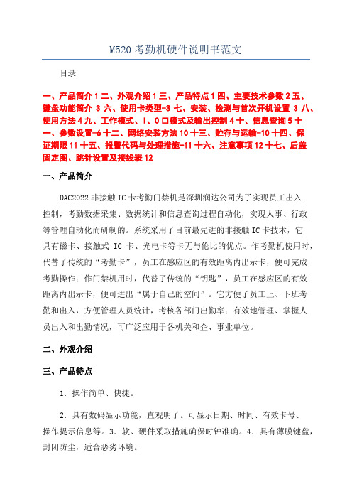
M520考勤机硬件说明书范文目录一、产品简介1二、外观介绍1三、产品特点1四、主要技术参数2五、键盘功能简介3六、使用卡类型-3七、安装、检测与首次开机设置3八、使用方法4九、工作模式、I、O口模式及输出控制4十、信息查询5十一、参数设置-6十二、网络安装方法10十三、贮存与运输-10十四、保证期限11十五、报警代码与处理措施-11十六、注意事项12十七、后盖固定图、跳针设置及接线表12一、产品简介DAC2022非接触IC卡考勤门禁机是深圳润达公司为了实现员工出入控制,考勤数据采集、数据统计和信息查询过程自动化,实现人事、行政等管理自动化而研制的。
系统采用了目前最先进的非接触IC卡技术,它具有磁卡、接触式IC卡、光电卡等卡无与伦比的优点。
作考勤机使用时,代替了传统的“考勤卡”,员工在感应区的有效距离内出示卡,便可完成考勤操作;作门禁机用时,代替了传统的“钥匙”,员工在感应区的有效距离内出示卡,便可进出“属于自己的空间”。
它方便了员工上、下班考勤和出入,方便管理人员统计,考核各部门出勤率;有效地管理、掌握人员出入和出勤情况,可广泛应用于各机关和企、事业单位。
二、外观介绍三、产品特点1.操作简单、快捷。
2.具有数码显示功能,直观明了。
可显示日期、时间、有效卡号、操作提示信息等。
3.软、硬件采取措施确保时钟准确。
4.具有薄膜键盘,封闭防尘,适合恶劣环境。
5.可设置特殊用户在出示用户卡后,再用键盘输入用户密码,密码识别后才能开启门,防止他人盗用别人的卡进入。
6.存储容量大,方便用户存储各种数据。
7.可根据持卡人的权限和时限识别是否有权进出。
8.可通过系统卡和键盘设置机号、日期、时间、工作模式、I、O口模式、继电器动作时间、输出控制模式;其中日期、时间也可通过联网由系统管理软件设置;9.可允许系统软件发行超过1万张卡,同时挂失超过1万张卡。
10.可记录持卡人进出的时间、身份等信息。
11.可与防盗、消防、监控等系统联用。
M56710FP资料
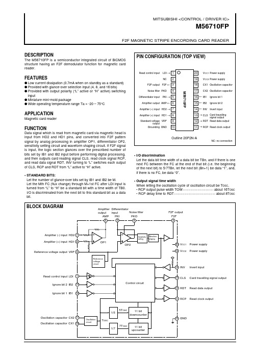
1 3 4 5 6 7 8 9 10 11 12 13 14 15 16 17 18 19 20
Pin name LDI F2F PKO PKI AMP HD2 HD1 VRF GND RCP RDT CLS INV IB2 IB1 CX2 CX1 VCC2 VCC1
Name Read control input F2F output Noise filter Differentiator input Amplifier output Amplifier (–) input Amplifier (+) input Reference voltage output Grounding Read clock output Read data output Card travelling signal output Invert input Ignore bit 2 Ignore bit 1 Oscillation capacitor Oscillation capacitor Power supply Power supply
signal output
Amplifier output AMP ← 6 Amplifier (–) input HD2 → 7
APPLICATION
Magnetic card reader
Amplifier (+) input HD1 → 8 Standard voltage VRF output Grounding GND
BLOCK DIAGRAM
Amplifier Differentiator Noise filter output input PKO AMP PKI 5 6 4
F2F output F2F 3
英瑞得mth5.0说明书
永诺35 1.8g说明书
宏锐永诺35-1.8G是一款最新推出的永磁直流电机,它具有更高的
效率、更轻的重量、更加紧凑的尺寸和更好的能源效率。
宏锐永诺35-1.8G采用金属印可模态和高密度磁源组件,具有强大的力量密度和高度稳定的特性,可以提供高效率、低噪音等优点。
精心设
计的冷却和加热系统可以保证持久的稳定性和低故障率,而且额外的
护套可以有效地防止例如塑料燃烧的高热量,从而增强使用性能。
此外,宏锐永诺35-1.8G还可以根据用户的要求进行定制,如封装形状、输出轴测量值、死区函数和控制器等。
通过使用完善的人机界面,它
可以满足多种类型和多种应用的需要,并且可以提供更快的响应时间,从而更好地控制和调节电机。
宏锐永诺35-1.8G电机采用隔离式安装,可以防止外界干扰引起的电磁冲击。
因此,它不仅可以更好地保护电缆和控制系统,而且可以确保
电机的精确工作和高可靠性。
11. M580 PWS

3
冗余电源(续)
●报警继电器端子块
●触点类型: 常开
1 2 1
●额定值: 24 VDC 2A; 240 VAC 2A
●复位按钮
●强制复位CPU模块 ●冷启动初始化模块 ●强制 ALARM 继电器为常开状态 ●强制“OK” LED灯熄灭状态
M580 Configuration V1.0
Schneider Electric | Industry Business | Training | February 2, 2021
●显示面板
●ACTIVE: ON – 模板处于“主” 状态
OFF – 模板处于“从” 状态
●OK:
ON – 所有输出电压工作正常
复位按钮没有激活
OFF – 24VDC 和 3.3VDC 异常.; 复位按钮激活
●RD :
ON – 24VDC 和 3.3VDC 正常; 复位按钮没有被激活(冗余)
OFF – 有一个电压模板停止运行
5
冗余电源(续)
特性 - BMX CPS 4022
M580 Configuration V1.0
Schneider Electric | Industry Business | Training | February 2, 2021
6
冗余电源(续)
比较 Quantum 和 X80 冗余电源
● 当前Quantum 方案: - 2个电源共享负载 - 相同的 MTBF
复位按钮被激活
注:
在模板自动检验阶段, ACT 和 RD LED灯将闪烁.
在初次上电的时候, 背板最左面的模块被设定为“主”.
M580 Configuration V1.0
Schneider Electric | Industry Business | Training | February 2, 2021
- 1、下载文档前请自行甄别文档内容的完整性,平台不提供额外的编辑、内容补充、找答案等附加服务。
- 2、"仅部分预览"的文档,不可在线预览部分如存在完整性等问题,可反馈申请退款(可完整预览的文档不适用该条件!)。
- 3、如文档侵犯您的权益,请联系客服反馈,我们会尽快为您处理(人工客服工作时间:9:00-18:30)。
1048576-BIT(131072-WORD BY8-BIT)CMOS STATIC RAMDESCRIPTIONFEATURESThe M5M5V108DFP,VP,KV are a 1048576-bit CMOS static RAM organized as 131072 word by 8-bit which are fabricated using high-performance triple-polysilicon and double metal CMOS technology. The use of thin film transistor (TFT) load cells and CMOS periphery result in a high density and low power static RAM.They are low standby current and low operation current and ideal for the battery back-up application.The M5M5V108DVP,KV are packaged in a 32-pin thin small outline package which is a high reliability and high density surface mount device(SMD).PackageAPPLICATIONSmall capacity memory unitsDirectly TTL compatible : All inputs and outputsEasy memory expansion and power down by S1,S2Data hold on +2V power supplyThree-state outputs : OR - tie capabilityOE prevents data contention in the I/O busCommon data I/OM5M5V108DFP ············32pin 525mil SOPM5M5V108DVP,RV············32pin 8 X 20 mm TSOPM5M5V108DKV,KR ············32pin 8 X 13.4 mm TSOP221048576-BIT(131072-WORD BY 8-BIT)CMOS STATIC RAMFUNCTIONThe operation mode of the M5M5V108D series are determined by a combination of the device control inputs S 1,S 2,W and OE.Each mode is summarized in the function table.A write cycle is executed whenever the low level W overlaps with the low level S 1and the high level S 2. The address must be set up before the write cycle and must be stable during the entire cycle.The data is latched into a cell on the trailing edge of W,S 1or S 2,whichever occurs first,requiring the set-up and hold time relative directly controls the output stage. Setting the OE at a high level,the output stage is in a high-impedance state, and the data bus contention problem in the write cycle is eliminated.A read cycle is executed by setting W at a high level and OE at a low level while S 1and S 2are in an active state(S 1=L,S 2=H).When setting S 1at a high level or S 2at a low level, the chip are in a non-selectable mode in which both reading and writing are disabled. In this mode, the output stage is in a high- impedance state, allowing OR-tie with other chips and memory expansion by S 1and S 2. The power supply current is reduced as low as the stand-by current which is specified as I CC3or I CC4, and the memory data can be held at +2V power supply, enabling battery back-up operation during power failure or power-down operation in the non-selected mode.FUNCTION TABLE1048576-BIT(131072-WORD BY 8-BIT)CMOS STATIC RAMABSOLUTE MAXIMUM RATINGSCAPACITANCE Symbol ParameterTest conditionspF pFUnit Max 810TypMinLimits V I =GND, V I =25mVrms, f=1MHz V O =GND,V O =25mVrms, f=1MHzInput capacitance Output capacitanceC I C OParameterSupply voltage Input voltageOutput voltage Power dissipationOperating temperature Storage temperatureUnit V V V mW °C °CConditionsWith respect to GND Ta=25°C7000~70– 65~150Ratings Symbol V cc DC ELECTRICAL CHARACTERISTICS (Ta=0~70°C, Vcc=2.7~3.6V, unless otherwise noted)Symbol ParameterV V V Max TypLimitsMin Test conditionsUnit V µA – 0.3*~4.6– 0.3*~Vcc + 0.3(Ta=0~70°C, unless otherwise noted)0~Vcc * –3.0V in case of AC ( Pulse width ≤ 30ns )Note 1: Direction for current flowing into an IC is positive (no mark).2: Typical value is Vcc = 3V, Ta = 25°CmA * –3.0V in case of AC ( Pulse width ≤ 30ns )µAµAV Vcc + 0.30.62.0–0.3*2.40.33Stand-by current0.4±1Active supply current Active supply currentVcc – 0.5±135V IH V IL V OH1V OH2V OL I I I O I CC1I CC2I CC3I CC4High-level input voltage Low-level input voltage High-level output voltage 1High-level output voltage 2Low-level output voltage Input currentOutput current in off-state Stand-by currentI OH = – 0.5mA I OH = – 0.05mAI OL = 2mA V I =0~VccS 1=V IH or S 2=V IL or OE=V IH V I/O =0~V CCS 1=V IL ,S 2=V IH ,other inputs=V IH or V IL Output-open(duty 100%)1) S 2≤ 0.2Vother inputs=0~V CC 2) S 1≥ V CC –0.2V,S 2 ≥ V CC –0.2Vother inputs=0~V CC S 1=V IH or S 2=V IL ,other inputs=0~V CC~25°C (Max 4.6)~40°C ~70°C1.23.612570ns 1MHz V I V O P d T opr T stg-H1048576-BIT(131072-WORD BY 8-BIT)CMOS STATIC RAM(2)READ CYCLE(3)WRITE CYCLESymbol Parametert CR Read cycle timeAddress access timeUnit ns ns ns ns ns ns ns ns ns ns ns nsSymbol ParameterUnit ns ns ns ns ns ns ns ns ns ns ns ns nsLimitst a(S1)t a(S2)t a(OE)t dis(S1)t dis(S2)t dis(OE)t en(S1)t en(S2)t en(OE)t V(A)t a(A)Limits AC ELECTRICAL CHARACTERISTICS (Ta=0~70°C, unless otherwise noted ) (1)MEASUREMENT CONDITIONSChip select 1 access time Chip select 2 access time Output enable access timeOutput disable time after S 1high Output disable time after S 2low Output disable time after OE high Output enable time after S 1low Output enable time after S 2high Output enable time after OE low Data valid time after address70707035252525701010510Write cycle time Write pulse width Address setup timeAddress setup time with respect to W Chip select 1 setup time Chip select 2 setup time Data setup time Data hold timeWrite recovery timeOutput disable time from W low Output disable time from OE high Output enable time from W high Output enable time from OE low252570550656565300055V CC 2.7~3.6VInput pulse level V IH =2.2V,V IL =0.4V Input rise and fall time 5nsReference level V OH =V OL =1.5V Output loads Fig.1, C L =30pFC L =5pF (for t en ,t dis )Transition is measured ± 500mV from steady state voltage. (for t en ,t dis ).....................................................................................includingscope and JIGDQFig.1 Output loadMin Max -70H Max Min t CW t w(W)t su(A)t su(A-WH)t su(S1)t su(S2)t su(D)t h(D)t rec(W)t dis(W)t dis(OE)t en(W)t en(OE)-70H1048576-BIT(131072-WORD BY 8-BIT)CMOS STATIC RAMRead cycleWrite (W (4)TIMINGDIAGRAMS DQ 1~8S 1S 2OEWA 0~16DQ 1~8S 1S 2OEA 0~161048576-BIT(131072-WORD BY 8-BIT)CMOS STATIC RAMWrite cycle (S 1control mode)Write cycle (S 2control mode)DQ 1~8S 1S 2WA 0~16DQ 1~8S 1S 2WA 0~16Note 3: Hatching indicates the state is "don't care".4: Writing is executed while S 2high overlaps S 1and W low.5: When the falling edge of W is simultaneously or prior to the falling edge of S 1or rising edge of S 2, the outputs are maintained in the high impedance state.6: Don't apply inverted phase signal externally when DQ pin is output mode.1048576-BIT(131072-WORD BY 8-BIT)CMOS STATIC RAMV CC = 3V1) S 2 ≤ 0.2V,other inputs = 0~3V 2) S 1 ≥ V CC –0.2V,S 2 ≥ V CC –0.2Vother inputs = 0~3V(Ta=0~70°C, unless otherwise noted)(3)POWER DOWN CHARACTERISTICS S 1control modePOWER DOWN CHARACTERISTICS(1)ELECTRICAL CHARACTERISTICS Power down set up time Power down recovery time(2)TIMING REQUIREMENTS (Ta=0~70°C, unless otherwise noted )t su (PD)t rec (PD)Symbol Parameterns MaxTypLimits Min Test conditionsUnit 05msV CCS 1S 2≤ 0.2VS 2control modeV CCS 2Symbol ParameterV V MaxTypLimits Min Test conditionsUnit µAV 20.2V CC (PD)V I (S1)V I (S2)I CC (PD)Power down supply voltage Chip select input S 1Chip select input S 2Power down supply current2.0~25°C ~40°C ~70°C-H1310V 0.6Vcc(PD)2.7V ≤Vcc(PD)Vcc(PD)<2.7V Note 7: On the power down mode by controlling S 1,the input level of S 2 must be S 2 ≥Vcc - 0.2V orS 2 ≤ 0.2V. The other pins(Address,I/O,WE,OE) can be in high impedance state.Keep safety first in your circuit designs!Mitsubishi Electric Corporation puts the maximum effort into making semiconductor products better and more reliable, but there is always the possibility that trouble may occur with them. Trouble with semiconductors may lead to personal injury, fire or property damage. Remember to give due consideration to safety when making your circuit designs, with appropriate measures such as (i) placement of substitutive, auxiliary circuits, (ii) use of non-flammable material or (iii) prevention against any malfunction or mishap.Notes regarding these materialsThese materials are intended as a reference to assist our customers in the selection of the Mitsubishi semiconductor product best suited to the customer's application; they do not convey any license under any intellectual property rights, or any other rights, belonging to Mitsubishi Electric Corporation or a third party.Mitsubishi Electric Corporation assumes no responsibility for any damage, or infringement of any third-party's rights, originating in the use of any product data, diagrams, charts, programs, algorithms, or circuit application examples contained in these materials.All information contained in these materials, including product data, diagrams, charts, programs and algorithms represents information on products at the time of publication of these materials, and are subject to change by Mitsubishi Electric Corporation without notice due to product improvements or other reasons. It is therefore recommended that customers contact Mitsubishi Electric Corporation or an authorized Mitsubishi Semiconductor product distributor for the latest product information before purchasing a product listed herein.The information described here may contain technical inaccuracies or typographical errors. Mitsubishi Electric Corporation assumes no responsibility for any damage, liability, or other loss rising from these inaccuracies or errors.Please also pay attention to information published by Mitsubishi Electric Corporation by various means, including the Mitsubishi Semiconductor home page ().When using any or all of the information contained in these materials, including product data, diagrams, charts, programs, and algorithms, please be sure to evaluate all information as a total system before making a final decision on the applicability of the information and products. Mitsubishi Electric Corporation assumes no responsibility for any damage, liability or other loss resulting from the information contained herein.Mitsubishi Electric Corporation semiconductors are not designed or manufactured for use in a device or system that is used under circumstances in which human life is potentially at stake. Please contact Mitsubishi Electric Corporation or an authorized Mitsubishi Semiconductor product distributor when considering the use of a product contained herein for any specific purposes, such as apparatus or systems for transportation, vehicular, medical, aerospace, nuclear, or undersea repeater use.The prior written approval of Mitsubishi Electric Corporation is necessary to reprint or reproduce in whole or in part these materials.If these products or technologies are subject to the Japanese export control restrictions, they must be exported under a license from the Japanese government and cannot be imported into a country other than the approved destination.Any diversion or reexport contrary to the export control laws and regulations of Japan and/or the country of destination is prohibited.Please contact Mitsubishi Electric Corporation or an authorized Mitsubishi Semiconductor product distributor for further details on these materials or the products contained therein.。
