M4000 and M5000系统在线硬件扩容指导
Sun SPARC Enterprise M3000 服务器安装指南说明书
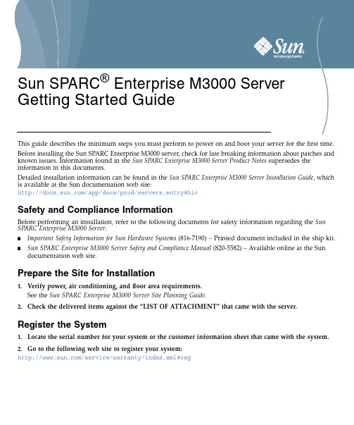
This guide describes the minimum steps you must perform to power on and boot your server for the first time.Before installing the Sun SPARC Enterprise M3000server,check for late breaking information about patches and known rmation found in the Sun SPARC Enterprise M3000Server Product Notes supersedes the information in this documents.Detailed installation information can be found in the Sun SPARC Enterprise M3000Server Installation Guide ,which is available at the Sun documentation web site:/app/docs/prod/servers.entry#hicSafety and Compliance InformationBefore performing an installation,refer to the following documents for safety information regarding the Sun SPARC Enterprise M3000Server :■Important Safety Information for Sun Hardware Systems (816-7190)–Printed document included in the ship kit.■Sun SPARC Enterprise M3000Server Safety and Compliance Manual (820-5582)–Available online at the Sun documentation web site.Prepare the Site for Installation1.Verify power,air conditioning,and floor area requirements.See the Sun SPARC Enterprise M3000Server Site Planning Guide.2.Check the delivered items against the “LIST OF ATTACHMENT”that came with the server.Register the System1.Locate the serial number for your system or the customer information sheet that came with the system.2.Go to the following web site to register your system:/service/warranty/index.xml#regSun SPARC ® Enterprise M3000Server Getting Started GuideInstall Optional ComponentsBefore installing the server into the rack,you must first install any optional components that you ordered with the server,such as DIMMs,PCIe cards,and so on.Refer to the Sun SPARC Enterprise M3000Server Service Manual for the instructions on installing optional components.Mount the System In a RackFor rackmounting instructions,refer to the instructions in the Sun SPARC Enterprise Rack Mounting Guide (online)and the Rail Kit Instructions which ships with the rails.Installation Steps for SPARC Enterprise M3000ServerFor quick installation and configuration,follow these steps.For more detailed information,see the SPARC Enterprise M3000Server Installation Guide .Caution –Make sure that the AC power source circuit breaker is in the OFF position beforeplugging in the AC power cables.▼Connecting the Cables1.Connect the power cables to the power supply units on the rear panel of the server.2.Connect the power cables to AC power supply system.This server is shipped with grounding-type (three-wire)power cables.Always connect the power cables into grounded power outlets.FIGURE 1Rear Panel of the ServerFigure Legend Location NumberComponent1Power supply unit 2PCIe slot3Serial port (for XSCF)4LAN port (for XSCF)5Gigabit Ethernet (GbE)port (for OS)12345e the brown RS232C cable (serial cable,RJ-45to DB-9)supplied with the server,and connect theadministration console to the serial port (see FIGURE 1,#3)on the rear panel of the server.You can use any of the following devices with a DB-9serial port as the administration console:ASCII terminal,workstation,terminal server (or a patch panel connected to a terminal server),or personal computer.A Serial-to-USB port adapter may be required for laptops.▼Initialize the XSCFThe following steps will log in to the XSCF Shell and initialize the XSCF settings.XSCF is a system control facility to set up and control the server.1.Set the mode switch on the operator panel to the Service mode ().The key for the operator panel is supplied with the server.FIGURE 2Operator Panel2.Turn the AC power source circuit breaker to "ON".After AC power is turned on,the server starts the XSCFinitialization that can take up to 5or more minutes.When the initialization completes,the XSCF STANDBY LED ()on the operator panel lights.3.After the XSCF initialization completes,enter default at the login prompt.Figure Legend Location No.Name1POWER LED 2XSCF STANDBY LED 3CHECK LED 4Power button5Mode switch (Key switch)login:default123454.Operate the mode switch within one minute according to the messages to change the mode switch.A login authentication timeout will occur after one minute.5.Confirm that the XSCF Shell prompt is displayed on the administration console.6.Initialize the XSCF settings.The following are the required settings for installation.To apply the settings,the XSCF unit must be reset with the applynetwork and rebootxscf commands.For details on the setting procedure,see the Sun SPARC Enterprise M3000/M4000/M5000/M8000/M9000Servers XSCF User’s Guide .7.Log in to the XSCF Shell with the user account and password that were set in the Step 6.▼Power On the Server1.The following steps will power on the server.a.Confirm that the mode switch on the operator panel is set to the Service mode ().b.From the XSCF Shell,enter the following console command:This switches you from the XSCF Shell to the domain console.c.Confirm that the XSCF STANDBY LED ()on the operator panel is on.d.Push the Power button ()on the operator panel to power on the server.The server starts and begins a self-diagnosis.Confirm that no error messages are displayed on the administration console during the boot process.e.Confirm that the POWER LED ()on the operator panel is turned on.f.Confirm that ok prompt is displayed on the domain console.The ok prompt is displayed after the self-diagnosis completes.Change the panel mode switch to Locked and press return...Leave it in that position for at least 5 seconds.Change the panel mode switch to Service, and press return...XSCF>SettingsCommandRegistration of an XSCF user account,password,and user privilegesRegistration of an user account of a field engineer (FE)(for maintenance)adduser ,password ,setprivileges Date and time settingssetdate ,settimezone Confirmation of the XSCF host public key showsshSSH/telnet settingssetssh ,settelnet Network interface,routing,and DNS-related settings setnetwork,setroute ,setnameserver etc.Altitude administration setting setaltitude Dual power feed option settingsetdualpowerfeedXSCF>console -d 0Connect to DomainID 0?[y|n]:yg.Press the Enter key,and then press the"#"and“.”(period)keys.This switches you from the domain console to the XSCF Shell.h.From the XSCF Shell,execute the fmdump command or showlogs command,and confirm that no errorsare found.2.Connect the system control network to a LAN port(see FIGURE1,#4)on the rear panel of the server withan Ethernet cable.3.Verify the hardware configuration by using the following commands on the administration consoleconnected to the system control network.Command Prompt Descriptionshowhardconf XSCF Shell All the components installed in the server and their statuses are displayed.Confirm that no asterisk(*)is displayed in front of any FRUs.showhardconf-u XSCF Shell Check the number of FRUs mounted on the server against the“PRODUCTTEST RECORD“that came with the server.probe-scsi-all ok Prompt Confirm that the CD-RW/DVD-RW drive unit and hard disk driveinstalled in the server are recognized.show-devs ok Prompt Confirm that each installed PCIe card is recognized.To switch from the XSCF console to the ok prompt,enter the console-d0command.To switch from the ok prompt to the XSCF console,press the enter key,and then press the"#"and"."(period)keys.4.Install additional hardware or peripheral devices.If not needed,proceed to the Step5.For details on how to add optional devices,such as additional memory or an additional PCIe card,see the Sun SPARC Enterprise M3000Servers Service Manual.To add an additional storage device or other peripheral device,see the manual supplied with the device.5.The following steps will connect the domain to the user network.If you isolate the domain from thenetwork,proceed to the Step1.The user network is a network which enables users to access the domain.a.Connect one end of an Ethernet cable to a GbE port(for the OS)(see FIGURE1,#5)on the rear panel ofthe server.You can connect the Ethernet cable to a GbE port(for the OS)or to the LAN port on a LAN card mounted in a PCIe slot(see FIGURE1,#2).b.Connect the other end of the Ethernet cable to the customer’s network environment.▼Boot the Solaris Operating System1.The following steps will boot the Solaris TM Operating System.The Solaris OS is preinstalled in the slot0of the hard disk drives.a.From the ok prompt of the domain console,execute the boot command.ok bootb.After the login prompt is displayed,log in with root account.2.Confirm the status of hardware operations and device connection by using SunVTS.For details,see the SunVTS User’s Guide.Manual Code C120-E549-01EN Part No. 820-5581-10, Rev. A October 2008Sun Microsystems, Inc.3.Make the initial settings for the domain.For details,see the Sun SPARC Enterprise M3000/M4000/M5000/M8000/M9000Servers Administration Guide .Sun SPARC Enterprise M3000Server Related DocumentationSun Contact InformationSystem Planning and Site Preparation •Sun SPARC Enterprise M3000Server Overview Guide •Sun SPARC Enterprise M3000Server Site Planning Guide System Installation •Sun SPARC Enterprise Equipment Rack Mounting Guide •Sun SPARC Enterprise M3000Server Installation Guide Administration•Sun SPARC Enterprise M3000Server Product Notes•Sun SPARC Enterprise M3000/M4000/M5000/M8000/M9000Servers Administration Guide •Sun SPARC Enterprise M3000/M4000/M5000/M8000/M9000Servers XSCF User’s Guide•Sun SPARC Enterprise M3000/M4000/M5000/M8000/M9000Servers XSCFReference ManualRepair and Troubleshooting •Sun SPARC Enterprise M3000Server Service ManualTopicURLTechnical support/service/contacting Submitting comments on this document /hwdocs/feedback Patch and firmware updates/support/index.jspCopyright 2008Sun Microsystems,Inc.All rights reserved.FUJITSU LIMITED provided technical input and review on portions of this material.Copyright 2008Sun Microsystems,Inc.Tous droits réservés.Entrée et revue tecnical fournies par FUJITSU LIMITED sur des parties de ce matériel.。
Sun SPARC Enterprise M4000 M5000 服务器产品说明.pdf_16938
Sun SPARC® EnterpriseM4000/M5000 服务器产品说明适用于 XCP 版本 1040 Sun Microsystems, Inc.文件号码 820-1371-102007 年 6 月,修订版 A请将有关本文档的意见和建议提交至:/hwdocs/feedback请回收版权所有 2007 Sun Microsystems, Inc., 4150 Network Circle, Santa Clara, California 95054, U.S.A. 及 FUJITSU LIMITED, 1-1, Kamikodanaka 4-chome, Nakahara-ku, Kawasaki-shi, Kanagawa-ken 211-8588, Japan 。
保留所有权利。
对于本文档中介绍的产品和技术,Sun Microsystems, Inc. 和 Fujitsu Limited 分别拥有相关的知识产权,此类产品、技术及本文档受版权法、专利法与其他知识产权法和国际公约的保护。
Sun Microsystems, Inc. 和 Fujitsu Limited 在此类产品、技术及本文档中拥有的知识产权包括(但不限于)在 /patents 中列出的一项或多项美国专利,以及在美国或其他国家/地区申请的一项或多项其他专利或待批专利。
本文档及其相关产品和技术的使用、复制、分发和反编译均受许可证限制。
未经 Fujitsu Limited 和 Sun Microsystems, Inc. 及其适用许可方(如果有)的事先书面许可,不得以任何形式、任何手段复制此类产品或技术或本文档的任何部分。
提供本文档并不意味着赋予您对相关产品或技术的任何明示或默示的权利或许可,而且本文档不包含也不表示 Fujitsu Limited 或 Sun Microsystems, Inc. 或各自分支机构作出的任何种类的任何承诺。
Sun SPARC Enterprise M4000 M5000 伺服器文档说明书

存取文件Sun SPARC® Enterprise M4000/M5000 伺服器的全套文件可在以下網址取得:/documentation備註 – 有關 Sun SPARC Enterprise M4000/M5000 伺服器硬體、軟體或文件的最新資訊,請參閱「Sun SPARC Enterprise M4000/M5000 Servers Product Notes」,網址為:/documentationSun SPARC Enterprise M4000/M5000 伺服器文件系統規劃與站點規劃• 「Sun SPARC Enterprise M4000/M5000 伺服器簡介指南」• 「Sun SPARC Enterprise M4000/M5000 伺服器站點規劃指南」• 「Sun SPARC Enterprise 設備機架裝配指南」系統安裝• 「Sun SPARC Enterprise M4000/M5000/M8000/M9000 Servers XSCFUser's Guide」• 「Sun SPARC Enterprise M4000/M5000/M8000/M9000 ServersAdministration Guide」Sun SPARC Enterprise M4000/M5000 伺服器工具組與伺服器包裝在一起,其中包括以下書籍:• 「Sun SPARC Enterprise M4000/M5000 伺服器入門指南」• 「Sun SPARC Enterprise M4000/M5000 伺服器安裝指南」• 「Sun SPARC Enterprise M4000/M5000 Servers Safety and ComplianceManual」管理• 「Sun SPARC Enterprise M4000/M5000/M8000/M9000 ServersAdministration Guide」• 「Sun SPARC Enterprise M4000/M5000/M8000/M9000 Servers XSCFUser's Guide」• 「Sun SPARC Enterprise M4000/M5000/M8000/M9000 Servers XSCFReference Manual」• 「Sun SPARC Enterprise M4000/M5000 Servers Product Notes」• 「Sun SPARC Enterprise M4000/M5000/M8000/M9000 ServersDynamic Reconfiguration (DR) User's Guide」修復與疑難排解• 「Sun SPARC Enterprise M4000/M5000 Servers Service Manual」全球化• 英文、法文、日文、韓文、簡體中文與繁體中文版的「Sun SPARCEnterprise M4000/M5000 伺服器入門指南」、「Sun SPARC EnterpriseM4000/M5000 伺服器安裝指南」、「Sun SPARC Enterprise M4000/M5000 Servers Safety and Compliance Manual」Sun SPARC Enterprise M4000/M5000 伺服器的安裝作業說明步驟 1• 確認電源、空調及底板面積需求。
SUN M4000更换内存(比较简单但还是共享出来)
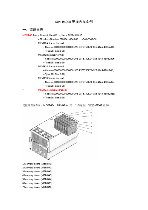
SUN M4000更换内存实例一、错误日志MEMB#0 Status:Normal; Ver:0101h; Serial:BF0843MAK5 ;+ FRU-Part-Number:CF00541-0545 06 /541-0545-06 ;MEM#0A Status:Normal;+ Code:ce0000000000000001M3 93T5750EZA-CE6 4145-480d2d38;+ Type:2B; Size:2 GB;MEM#0B Status:Normal;+ Code:ce0000000000000001M3 93T5750EZA-CE6 4145-480d2d0f;+ Type:2B; Size:2 GB;MEM#1A Status:Normal;+ Code:ce0000000000000001M3 93T5750EZA-CE6 4145-480d2dff;+ Type:2B; Size:2 GB;MEM#1B Status:Normal;+ Code:ce0000000000000001M3 93T5750EZA-CE6 4145-480d2d6d;+ Type:2B; Size:2 GB;* MEM#2A Status:Degraded;+ Code:ce0000000000000001M3 93T5750EZA-CE6 4145-480d2de8;+ Type:2B; Size:2 GB;定位错误内存条:MEMB#0:MEM#2A:第一个内存板,(图是M5000机器)1 Memory board (MEMB#0)2 Memory board (MEMB#1)3 Memory board (MEMB#2)4 Memory board (MEMB#3)5 Memory board (MEMB#4)6 Memory board (MEMB#5)7 Memory board (MEMB#6)8 Memory board (MEMB#7)1 MEM#2A, Memory Slot (Group A)2 MEM#2B, Memory Slot (Group B)3 MEM#3A, Memory Slot (Group A)4 MEM#3B, Memory Slot (Group B)5 MEM#1B, Memory Slot (Group B)6 MEM#1A, Memory Slot (Group A)7 MEM#0B, Memory Slot (Group B)8 MEM#0A, Memory Slot (Group A)二、操作步骤:1、再次查看报错信息,定位错误内存条。
SPARC Enterprise M4000 M5000服务器文档说明书
Accessing the DocumentationThe full documentation set for SPARC Enterprise M4000/M5000servers can be found at:/pls/topic/lookup?ctx=E19855-01&id=homepage/pls/topic/lookup?ctx=E19580-01&id=homepageFor translated versions of the documentation,go to the /technetwork/documentation/sparc-mseries-servers-252709.html web site,then select your language to get the documentation set in your language.Note –For late-breaking information about the SPARC Enterprise M4000/M5000servers hardware,software,or documentation,refer to the SPARC Enterprise M3000/M4000/M5000/M8000/M9000Servers Product Notes at:/technetwork/documentation/sparc-mseries-servers-252709.html.SPARC Enterprise M4000/M5000 Servers Getting Started GuideSPARC Enterprise M4000/M5000Servers DocumentationSystem Planning and Site Preparation •SPARC Enterprise M4000/M5000Servers Overview Guide •SPARC Enterprise M4000/M5000Servers Site Planning Guide •SPARC Enterprise Equipment Rack Mounting GuideSystem Installation •SPARC Enterprise M4000/M5000Servers Installation Guide •SPARC Enterprise M4000/M5000Servers Service Manual•SPARC Enterprise M4000/M5000Servers Safety and Compliance Guide •SPARC Enterprise M3000/M4000/M5000/M8000/M9000Servers User’s Guide for XSCF•SPARC Enterprise M3000/M4000/M5000/M8000/M9000Servers Administration GuideThe SPARC Enterprise M4000/M5000servers kit is packaged with the server and includes the following books:•SPARC Enterprise M4000/M5000Servers Getting Started Guide •Important Legal and Safety Information•SPARC Enterprise M4000Server Unpacking Guide•SPARC Enterprise M5000Server Unpacking GuideAdministration•SPARC Enterprise M3000/M4000/M5000/M8000/M9000ServersAdministration Guide•SPARC Enterprise M3000/M4000/M5000/M8000/M9000Servers User’sGuide for XSCF•SPARC Enterprise M3000/M4000/M5000/M8000/M9000Servers XSCFReference Manual•SPARC Enterprise M4000/M5000/M8000/M9000Servers Capacity onDemand(COD)User’s Guide•SPARC Enterprise M3000/4000/M5000/M8000/M9000Servers Product Notes•SPARC Enterprise M4000/M5000/M8000/M9000Servers DynamicReconfiguration(DR)User’s GuideRepair and Troubleshooting •SPARC Enterprise M4000/M5000Servers Service Manual •SPARC Enterprise M3000/M4000/M5000/M8000/M9000Servers AdministrationGuideInstallation Task Map for SPARC Enterprise M4000/M5000Servers Step1•Verify power,air conditioning,and floor area requirements.—Refer to the SPARCEnterprise M4000/M5000Servers Site Planning Guide and the SPARC Enterprise EquipmentRack Mounting Guide.Step2•Set up the equipment rack.—Refer to the SPARC Enterprise Equipment Rack MountingGuide.Step3•If your server was preinstalled in an equipment rack,proceed to Step5to connect yourconsole to a server.•If your server needs to be rackmounted in an equipment rack,proceed to Step4.Step4•Mount the server in the equipment rack.—Refer to the SPARC Enterprise EquipmentRack Mounting Guide.Step5•Connect the console to a server.—Refer to the SPARC Enterprise M4000/M5000ServersInstallation Guide.Step6•Connect the power cables.—Refer to the SPARC Enterprise M4000/M5000ServersInstallation Guide.Step7•Power on the input power source.—Refer to the SPARC Enterprise M4000/M5000Servers Installation Guide.Step8•Prepare information for hardware configuration.—Refer to the SPARC EnterpriseM3000/M4000/M5000/M8000/M9000Servers User’s Guide for XSCF.Step9•Power on the server.Check that POST runs successfully on the eXtended systemcontrol facility unit(XSCFU)and confirm there are no errors.—Refer to the SPARCEnterprise M4000/M5000Servers Installation Guide.Step10•Set up the XSCFU for network access.—Refer to the SPARC Enterprise M3000/M4000/M5000/M8000/M9000Servers Administration Guide.Step11•If additional hardware or peripheral devices are to be installed into your server,proceed to Step12.•If additional hardware or peripheral devices are not to be installed into the server,proceed to Step16.Step12•Turn off the input power source.—Refer to the SPARC Enterprise M4000/M5000ServersInstallation Guide.Step13•Install additional hardware or peripheral devices.—Refer to the documentation thatcame with the hardware or peripheral devices for details.Step14•Turn on the input power source.—Refer to the SPARC Enterprise M4000/M5000ServersInstallation Guide.Step15•Allow each domain to run through POST and confirm there are no errors.Step16•Check the network settings and connections.—Refer to the SPARC Enterprise M4000/M5000Servers Installation Guide.Step17•Confirm operation by using Oracle VTS software.—Refer to the SPARC EnterpriseM4000/M5000Servers Installation Guide and the Oracle VTS user’s guide.Step18•Make the initial settings for each domain.—Refer to the SPARC Enterprise M3000/M4000/M5000/M8000/M9000Servers Administration Guide.Accessing DocumentationYou can view,print,or purchase a broad selection of documentation,including localized versions,at:/technetwork/documentation/sparc-mseries-servers-252709.html Contacting Technical SupportIf you have technical questions about this product that are not answered in this document,go to:https://Copyright©2007,2011,Oracle and/or its affiliates.All rights reserved.FUJITSU LIMITED provided technical input and review on portions of this material. Copyright©2007,2011,Oracle et/ou ses affiliés.Tous droits réservés.Entrée et revue tecnical fournies par FUJITSU LIMITED sur des parties de ce matériel.Part No.: E21595-01。
M4000-M5000更换XSCF卡过程

M4000-M5000更换扩展系统控制卡(XSCF卡)1、更换前确认上电机器状态,面板指示灯没有告警,可以用下列命令看看当前状态:XSCF> showhardconfXSCF> showhardconf -uXSCF> showstatus2、机器下电,并断开所有连接机器的电缆。
3、拔出XSCFU,并插入准备替换的XSCFU。
4、给机器接入电源线,并给电源线通电。
5、因为两块XSCFU的主机序列号不一致,在启动初始化的时候会进行提示更改当前主机框架序列号:***** WARNING *****XSCF initialization terminate because system data in XSCF/OPNL are mismatch.Start procedure for system data selection.Please select system data according to the instructionPlease input the chassis serial number : BDF1051F54(当前主机前面板右上部上贴的SN号)1:PANELPlease select the number : 16、输入之后系统会初始化XSCF卡三至五分钟,初始化完成后需要将机器断电,然后再给机器上电,开始第二次的XSCF卡初始化。
7、初始化完成后,会提示当前XSCF卡与机器内版本不同:Jan 1 00:23:58 localhost XSCF[106]: XSCF Initialize complete.login: defaultChange the panel mode switch to Service and press return...Leave it in that position for at least 5 seconds. Change the panel mode switch to Locked, and press return...XCP version of Panel EEPROM and XSCF FMEM mismatched,Panel EEPROM=1093, XSCF FMEM=1092换入的XSCFU同原先的版本不一致,需要升级。
Oracle Solaris 操作系统及相关硬件兼容性说明说明书
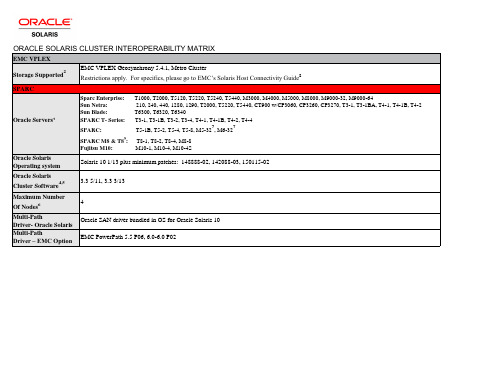
1. Go to My Oracle Support or for minimum supported Oracle Solaris operating environment versions, HBAs, patches and other supported options for list servers. This matrix is intended only to be a high level overview of support. It is not a configuration guide. 2. Please refer to EMC's interoperability matrix at https:/// for specific configurations, min microcode versions, volume manager support, notes and any restrictions. For configurations where TimeFinder or SRDF are being used, please refer to the white paper, “Integration of EMC SRDF and TimeFinder with Oracle Solaris Cluster” on EMC’s Avatar and PowerLink sites. You may also refer to the OSC 3.3 5/11 documentation: Campus Cluster Data Replication: /cd/E18728_01/html/821-2847/datarep.html#scrolltoc Geo Edition: /cd/E22702_01/html/821-2756/index.html 3. “Native” HBAs supported by Oracle Solaris: https:///display/SystemsComm/Home Non-Oracle/Sun HBAs require that Oracle/Sun drivers be utilized. 4. QFS is supported. 5. EMC supports ZFS and MPxIO in a Oracle Solaris Cluster environment. 6. 16 Gb HBAs are supported in specific OSC and Solaris releases with a very specific set of servers. Please consult MOS for details. Helpful link: /technetwork/documentation/oracle-storage-networking-190061.html 7. Supported only on Solaris 10 guest domains. See server documentation for specifics. 8. Go to https:/// Select ‘Documents’ in the upper tool bar and select ‘Host Connectivity guides’, then select ‘Oracle Solaris’. Start at approximately page 231 for the statement of support for SCSI-3. 9. Supported only on Solaris 10 guest domains with Oracle Solaris Cluster 3.3 3/13 if the storage is supported with Oracle Solaris Cluster 4.4 as well.
大学数字化校园建设项目数据中心硬件系统设计方案
大学数字化校园建设项目数据中心硬件系统设计方案1.1.1.方案设计1.1.1.1.方案概述本方案是一个以应用为导向的硬件平台选型配置方案。
所以,所有的硬件选型及配置均基于用户的具体应用环境,以符合系统应用环境要求为标准,力争搭建优秀的应用平台。
经过细致的分析和综合考虑,我们选择了Sun SPARC Enterprise系列服务器和Sun Storage 系列存储,Sun Solaris 10 操作系统以及Sun Cluster3.2等软硬件搭建了一个综合,完善的应用平台。
综合类似案例建设经验,我们提供合适的服务器设备及其相关软件的配置方案,其概要如下:核心数据和关键应用支撑平台---2台M8000服务器和1台M5000服务器,每台M8000服务器各配置4个CPU板(每个板上均有4个主频为2.88GHz的SPARC64 VI I四核处理器),128G内存;M5000服务器配置2个系统板(每个系统板配置4个主频为2.53G的SPARC64 VI I四核处理器),128G内存;这些服务器均划分4个硬件域,每个硬件域安装独立的操作系统及相关应用软件。
身份认证支撑平台---2台M5000服务器,每台配置8个主频为2.53G的SPARC64 VI I四核处理器,256G内存以满足大学身份认证系统高访问性的需求。
校园卡系统专业数据支撑平台---2台M5000服务器,每台配置4个主频为2.53G的SPARC64 VI I四核处理器,64G 内存,以提高学校管理和服务的工作效率,降低相关数据统计工作的复杂性和劳动强度。
存储系统---2台Sun Storage 7410磁盘存储和VTL4310虚拟带库作为存储系统的组成部分,其中,新老校区各配置1台S7410磁盘存储,各存储设备上均集成了IP 远程数据复制软件,通过现有的跨校区网络将数据从老校区复制到新校区的S7410上,实现了数据级远程灾备;而VTL4310虚拟带库则作为学校的数据归档存储。
SPARC Enterprise M3000 服务器入门指南说明书

SPARC Enterprise M3000 服务器入门指南本指南介绍首次打开服务器电源并引导服务器所必须执行的基本步骤。
安装 SPARC Enterprise M3000 服务器之前,请检查关于修补程序的最新信息以及已知问题。
《SPARC EnterpriseM3000/M4000/M5000/M8000/M9000 服务器产品说明》中的信息优先级高于本文档中的信息。
《SPARC Enterprise M3000 服务器安装指南》中介绍了详细的安装信息,您可以通过文档 Web 站点获取该指南:/technetwork/documentation/sparc-mseries-servers-252709.html安全与法规遵从性信息执行安装之前,请参阅以下文档了解有关 SPARC Enterprise M3000 服务器的安全信息:■重要的法律和安全信息-产品包装箱中随附了此文档的印刷版本。
■《SPARC Enterprise M3000 Server Safety and Compliance Guide》-可通过文档 Web 站点联机获取该文档。
准备场地进行安装1.检验电源、空调和占地面积要求。
请参见《SPARC Enterprise M3000 服务器场地规划指南》。
2.对照服务器附带的“附件列表”检查交付的物品。
注册系统1.找到系统的序列号或者系统随附的客户信息表。
2.请访问以下 Web 站点注册系统:/service/warranty/index.xml#reg安装可选组件将服务器安装到机架中之前,首先必须安装随服务器一起订购的任何可选组件,如 DIMM、PCIe 卡等。
有关安装可选组件的说明,请参阅《SPARC Enterprise M3000 Server Service Manual》。
将系统装配到机架中有关机架装配说明,请参阅《SPARC Enterprise 设备机架装配指南》(联机版本)和滑轨随附的滑轨工具包说明。
Sun SPARC Enterprise M4000M5000 服务器入门指南
访问文档可从以下位置获取 Sun SPARC® Enterprise M4000/M5000 服务器的完整文档集:/documentation注 – 有关 Sun SPARC Enterprise M4000/M5000 服务器硬件、软件或文档的最新发布信息,请参阅《Sun SPARC Enterprise M4000/M5000 Servers Product Notes》,网址为:/documentationSun SPARC Enterprise M4000/M5000 服务器文档系统规划和场地准备●《Sun SPARC Enterprise M4000/M5000 服务器概述指南》●《Sun SPARC Enterprise M4000/M5000 服务器场地规划指南》●《Sun SPARC Enterprise 设备机架装配指南》系统安装●《Sun SPARC Enterprise M4000/M5000/M8000/M9000 Servers XSCFUser's Guide》●《Sun SPARC Enterprise M4000/M5000/M8000/M9000 ServersAdministration Guide》Sun SPARC Enterprise M4000/M5000 服务器工具包随服务器一起提供,其中包括以下几本书:●《Sun SPARC Enterprise M4000/M5000 服务器入门指南》●《Sun SPARC Enterprise M4000/M5000 服务器安装指南》●《Sun SPARC Enterprise M4000/M5000 Servers Safety and ComplianceManual》管理●《Sun SPARC Enterprise M4000/M5000/M8000/M9000 ServersAdministration Guide》●《Sun SPARC Enterprise M4000/M5000/M8000/M9000 Servers XSCFUser's Guide》●《Sun SPARC Enterprise M4000/M5000/M8000/M9000 Servers XSCFReference Manual》●《Sun SPARC Enterprise M4000/M5000 Servers Product Notes》●《Sun SPARC Enterprise M4000/M5000/M8000/M9000 ServersDynamic Reconfiguration (DR) User's Guide》修复和故障排除●《Sun SPARC Enterprise M4000/M5000 Servers Service Manual》全球化●《Sun SPARC Enterprise M4000/M5000 服务器入门指南》、《SunSPARC Enterprise M4000/M5000 服务器安装指南》和《Sun SPARCEnterprise M4000/M5000 Servers Safety and Compliance Manual》的英文版、法文版、日文版、韩文版、简体中文版和繁体中文版Sun SPARC Enterprise M4000/M5000 服务器的安装任务图●如果服务器需要架装在设备机架中,请继续执行步骤 4。
SUN设备XSCF模式使用及命令详解

这是sun M4000,M5000等M系列的底层口,XSCF控制卡进入提示符为XSCF >用户名:eis-installer密码:eis-installer如果用户的密码忘记了,还有一个默认缺省用户default,输入用户名,如果是第一次登录,请输入缺省用户:default。
login: default显示类似如下信息:Change the panel mode switch to Service and press return...1. 在5~10秒钟间,将钥匙插入M4000前面板的钥匙孔中,将开关旋至“Service”位置,并按“Enter”键。
显示类似如下信息:Leave it in that position for at least 5 seconds. Change the panel mode switch to Locked, and press return...2. 在5~10秒钟间,将开关旋至“Locked”位置,并按“Enter”键。
显示类似如下信息:XSCF>SUN <wbr>设备XSCF模式使用及命令详解说明:如果没有出现“XSCF>”字样,则证明没有登录上,请重新执行登录的过程。
还可以创建用户1. 执行如下命令创建监控用户:XSCF> adduser eis-installerXSCF> setprivileges eis-installer platadm useradm auditadm fieldengXSCF> password eis-installerNew XSCF password:Retype new XSCF password:SUN <wbr>设备XSCF模式使用及命令详解说明:输入的口令必须包含以下内容:·至少2个字母·至少1个数字或1个特殊字符·至少8至16个字符一旦设置了口令,eis-installer用户将拥有完全访问权限,且可执行所有的命令。
SPARC Enterprise M5000 简易操作及维护手册
SPARC Enterprise M5000简易操作及维护手册文档版本控制版本 1.0日期 2009-03-09维护人何朝东富士通(中国)信息系统有限公司技术支持部目录一.SPARC Enterprise概述 (3)二.M5000机器外观视图 (3)三.M5000机器的连接和使用 (7)㈠ 串口连接 (7)㈡.XSCF LAN连接 (12)㈢普通网卡连接 (13)四.M系列机器Domain及OS的启动和console的切换 (13)五. OS里面的一些常规操作(通用命令) (16)六.出现问题时需要采取的一些操作及步骤 (17)㈠当系统还能够正常运行时 (17)㈡当系统无法正常运行时 (21)一.SPARC Enterprise概述:SPARC Enterprise家族由中高端的M系列(M4000,M5000,M8000,M9000)和低端的T系列(如T5220)组成,运行的都是Solaris操作系统。
像所有的UNIX服务器一样,它们都有自己的Service Processor(一般都是一块独立的管理卡,通电即可检测机器整体的状态,与主机OS是否启动没有关系)。
SPARC Enterprise家族M系列上面配置的都是XSCF管理卡,XSCF管理卡的操作都是一样的,而M4000,M5000都只配有一块XSCF管理卡。
本文主要讲述M5000的使用和日常维护。
因为有XSCF管理卡,所以机器的实际启动过程是XSC F→OBP(ok提示符下,与以前的sun机器相同)→OS。
二.M5000机器外观视图M5000机器的整体布局示意图如下:M5000机器的前视图类似如下(注意硬盘的槽位上面是有编号的):M5000机器右上角的放大图类似如下:如果机器出现硬件故障,一般需要客户提供类似如图的MODEL和SN。
一般情况下硬件如果有故障或报错,告警灯都会亮起。
M5000机器的后视图类似如下:M5000机器的后视图下部电源接口旁边的是IOU集成的2个网口,如图从右到左分别是ETHERNET#0和ETHERNET#1,它们在系统里面的名字分别是:bge0 bge1。
华为S2200T存储在线扩容教程

应用环境:华为S2200T 存储一台,原来装有7个2T 的硬盘,做了RAID5阵列,一个热备盘,现空间不够需要增加1个2T 硬盘,前提是不影响原来的数据。
■通口日函立.Q)牢好EEftlfrEi ・片IDSfrH'♦曲口工♦»口a —。
L2S;,WEft•I SPWKL:■:BEM新增硬盘后,用OceanStoCSM 管理软件连上存储确认新增硬盘被存储系统识别并运行正常。
095要即轲。
।ISMI:;J3MartCacTR池就薄利年知宿回」LUN 理的F^AIDOQI J9SB9.197.WG HD :Q空帝用里OMBR AI D&山皿里 ■ 奥矍*期 口/数里6 魅用橘正第 于狙侬救 - 运用稔在技犷音进度3-尚目造力,强atss匚值QU ai&mssmi 鼬.4nI 上XI &育蜥费 :油*«;.O cam时品 1息),第口1litT J SM Z1SSFP3Ft 2吠35Cf?Cd 心।□miy M.3U FASliD9«GI 王军 皎7飒ZmrW2EDM. AMl 墟STCGi* 0(012? M.3^ w 1期1函UIiW72KMZiK3F?M*jMW..EiO23Mi7CG1ft.I □m 工 rj.su K^S lUSiHGI £Tf 初 T 2M 口hWMDKR. AsiazzcFEG-ia.M.S^iE^E4飒2CKIGI j£V 有 7ZWZ1JCWW3MKHJ..OK Zlfll23(5CTCG1iOl..1口由4 通蛙瓶m1浦口MCIM 的1汕Z1X3BMOM..苦53例?CGid.□0小 M.3A5ima1.!M3Wni 王* affe^aa 73WZ1»KEW?MW K ZI023557CG10 pfll .迎室1S93MCIK柜a7-MlZISSPVJPMIDn&m!3SC7C£^ia.KE |期1拉出|39帆贴息|ja-iittt |始EM 粉外|修将弓|ACqfl |41岫星易卜在导航树上,选择“存储资源〉块存储池”,在右侧信息展示区中选择需要扩容的RAID组,单击“扩容”。
SPARC Enterprise M系列服务器产品说明(适用于 XCP 版本 1112)说明书

SPARC Enterprise M3000/M4000/M5000/ M8000/M9000服务器产品说明(适用于XCP版本1112)文件号码E35704–022012年10月版权所有©2012,Oracle和/或其附属公司。
保留所有权利。
本软件和相关文档是根据许可证协议提供的,该许可证协议中规定了关于使用和公开本软件和相关文档的各种限制,并受知识产权法的保护。
除非在许可证协议中明确许可或适用法律明确授权,否则不得以任何形式、任何方式使用、拷贝、复制、翻译、广播、修改、授权、传播、分发、展示、执行、发布或显示本软件和相关文档的任何部分。
除非法律要求实现互操作,否则严禁对本软件进行逆向工程设计、反汇编或反编译。
此文档所含信息可能随时被修改,恕不另行通知,我们不保证该信息没有错误。
如果贵方发现任何问题,请书面通知我们。
如果将本软件或相关文档交付给美国政府,或者交付给以美国政府名义获得许可证的任何机构,必须符合以下规定:ERNMENT END USERS:Oracle programs,including any operating system,integrated software,any programs installed on the hardware,and/or documentation,delivered to U.S. Government end users are"commercial computer software"pursuant to the applicable Federal Acquisition Regulation and agency-specific supplemental regulations.As such,use,duplication,disclosure,modification,and adaptation of the programs,including any operating system,integrated software,any programs installed on the hardware,and/or documentation,shall be subject to license terms and license restrictions applicable to the programs.No other rights are granted to the ernment.本软件或硬件是为了在各种信息管理应用领域内的一般使用而开发的。
富士通 XSCF 完全傻瓜配置手册

XSCF完全傻瓜配置手册文档版本控制版本 1.0 1.1日期2008-06-22 2008-06-29维护人何朝东何朝东富士通(中国)信息系统有限公司技术支持部2008-06-29目录一.文档说明---------------------------------------------------------------3二.XSCF和ILOM比较之我见(以M4000和T5120为例)---------4三.XSCF基本配置步骤-------------------------------------------------5四.XSCF非常有用的配置(提高管理性)-------------------------14五.DOMAIN配置概述(M4000一般不需要配置)-------------17六.OS的安装及console的切换----------------------------------------20七.XCP的升级-----------------------------------------------------------24八.XSCF定位问题的方法及步骤------------------------------------27一.文档说明:本手册不是原理手册,完全是一个操作手册。
如果对相关概念有任何疑问,请查看相关手册。
同样由于版本更新的问题,命令及相关参数可能有较大变化,而且现在正是fujitsu产品更新换代频繁的时期,去现场作业前请下齐最新的手册,下面我只列出最基本的手册:Getting Started Guide(C120-E345-03EN) (列出了M4000&M5000所有参考数目)Overview Guide(C120-E346-03ZH)SPARC Enterprise M4000(共19页,看完可以快速对M4000的硬件有个比较全面的认识)Instance Priority(共9页,M4000&M5000&M8000&M9000)Site Planning Guide(C120-H015-03EN) (对环境的要求等)Installation Guide(C120-E351-03EN)SPARC Enterprise Hardware Platform GuideAdministration Guide(C120-E331-05EN)XSCF User's Guide(C120-E332-05EN)XSCF Reference Manual(C120-E333-05EN) (下文中提到的所有XSCF的命令在XSCF Reference Manual都可以找到,而且有详细的参数说明)Dynamic Reconfiguration (DR) User's Guide(C120-E335-04EN)Capacity on Demand (COD) User's Guide (C120-E336-04EN)Service Manual(C120-E352-03EN)SPARC Enterprise M4000&M5000 MAINTENANCE MANUAL(R11B-0926-01EN)二. XSCF和ILOM比较之我见(以M4000和T5120为例):XSCF和ILOM都是运行在Service Processor上的Firmware。
NVIDIA Quadro 图形卡快速入门指南说明书

NVIDIA® QUADRO®QUICK START GUIDEThank you for choosing the NVIDIA® Quadro®graphics card.This quick start guide covers the NVIDIA Quadro GP100, P6000, P5000,P4000, P2000, P1000, P620, P600, P400, M6000 24GB, M5000, M4000,M2000, K2200, K1200, K620, and K420 graphics cards. Before you begin, review the following Minimum System Requirements list to ensure your system meets the minimum hardware and software specification for your graphics card.Minimum System Requirements>MotherboardPCI Express x16 slot>Operating System• Microsoft Windows 10, 8.1, 8, 7 (all 32-bit and 64-bit)• Linux 32-bit or 64-bit on:- Red Hat Enterprise Linux 7.x, 6.x, 5.x, 4.x, 3.x- SUSE Linux Enterprise Desktop 13.x, 12.x, 11.x 10.x- OpenSUSE 13.x, 12.x, 11.x, 10.x- Fedora up to 24- Ubuntu 16.x, 15.x, 14.x, 13.x, 12.x, 11.x, 10.x, 9.x, 8.x, 7.x• Solaris>Processor• Intel Core i5, i7 or Xeon processor or later• AMD Phenom or Opteron class processor or later>System MemoryMinimum of two (2) GB memory, eight (8) GB or higher recommended >Blu-ray, DVD-ROM/CD-ROM drive, or Internet connection for driver installationENIncluded equipment with each NVIDIA Quadro graphics card.!ATTENTION: Static electricity can severely damage electronic components. Take the following precautions when installing your new NVIDIA Quadro graphics card: >Before touching any electronic parts, discharge the static electricity from your body by touching the internal metal frame of your system while it is unplugged. >Do not remove your card from the packaging clamshell until you are ready to install it. Whenever you remove a card from your system, always place it back in the clamshell.>Do not allow clothing or jewelry touch any electronic parts.>When handling your graphics card, hold it by the edges and avoid touching any circuitry or the PCIe connector.11 Remove the current graphics driver installed on the host system.• Go to Start\Control Panel\Programs and Features• Remove the current graphics driver.2 Power down your system.3 Unplug the power cord from the AC power source.4 Remove the side panel from your system to gain access to themotherboard.Note: Reference your specific computer documents for instructionson accessing the motherboard in your computer.5 R emove the existing graphics card if present. If a retention bar is holdingthe card in place, remove the screw securing the card.OR, If there is no existing graphics card, remove the accessEN6 Install the card into the primary x16 PCI slot. Press gently on thecard until it is seated securely in the slot.Install the graphics card into the primary x16 PCI slot.The Quadro GP100, P6000, P5000, M6000 24GB, and M5000 graphics cards are dual-slot cards and will cover the adjacent slot. The remaining graphic cards are single-slot cards.7 Secure the card to the system frame using the screw(s) removedin step 5.8 Connect the supplied auxiliary power cable(s) from the power supply to theback edge of the Quadro GP100, P6000, P5000, M6000 24GB, M5000,P4000, or M4000 graphics card.Note: Use the recommended power connector guidelines at /quadropowerguidelines .9 Install the side panel removed in step 4.1 Connect the display cable(s) to your Quadro graphics card.2Reconnect your power cord to the workstation.DisplayPort ConnectorSupports single-lane transfer rates over a single cable. The interface is primarily used to connect a video source to a display device such as a computer monitor.Mini-DisplayPort Connector DVI ConnectorsUse this to connect a digital display or, with an adapter, a VGA display using DVI-to-VGA adapter.DisplayPort ConnectorDVI-to-VGA Adapter(Optional - For use with DVI-IDriver InstallationWith the hardware installed, it is now time to install the graphics driver.1 Power up your computer, start Windows or Linux, and login with anaccount that has Administrator rights.Note: Since there is no GPU driver currently loaded, the display mayrun at reduced resolution or image quality.2 Download and install the driver.• Select and download the driver from /drivers. Launch the downloaded executable file, then follow the installer guides tocomplete installation.• Insert the software installation disc and follow directions for driverinstallation.The installer may require you to reboot your system once the driverinstallation is complete.Congratulations! Your NVIDIA Quadro graphicscard is now ready to use!。
炼焦行业焦炉加热自动控制系统_庞嘉嘉

总第182期2011年第2期H E B E I ME T A L L U RG YT o t a l 1822011,N u m b e r 2收稿日期:2010-12-29作者简介:庞嘉嘉(1980-)男,2006年毕业于河北科技大学电子与信息技术专业,在石家庄焦化集团有限责任公司工作,E-m a i l :p j s -m a i l z h @126.c o m炼焦行业焦炉加热自动控制系统庞嘉嘉(石家庄焦化集团有限公司,河北石家庄050031)摘要:介绍了石家庄焦化集团炼焦生产过程中焦炉加热自动控制系统的应用,并阐述了自动控制系统的原理、组成及系统功能等。
通过应用该系统在稳定加热、降低炼焦耗能、提高焦炭质量、劳动生产率、改善操作环境以及延长焦炉寿命等方面起到重要作用。
关键词:焦炉;加热;自动控制系统中图分类号:T Q 522.16 文献标识码:B文章编号:1006-5008(2011)02-0026-03A U T O M A T I CC O N T R O LS Y S T E M O FC O K EO V E NH E A T I N GP a n g J i a j i a(S h i j i a z h u a n gC o k e a n d C h e m i s t r y G r o u pC o .,L t d .,S h i j i a z h u a n g ,H e b e i ,050031)A b s t r a c t :I t i s i n t r o d u c e da p p l i c a t i o no f a u t o m a t i c c o n t r o l s y s t e m o f c o k eo v e nh e a t i n g ,s t a t e di t sp r i n c i p l e ,c o m p o s i t i o na n d s y s t e m f u n c t i o n s .I t p l a y s a n i m p o r t a n t r o l e i n s t a b i l i z i n gh e a t i n g ,r e d u c i n g e n e r g y c o n s u m p -t i o ni nc o k e m a k i n g ,i m p r o v i n gq u a l i t y o f c o k e ,r a i s i n gl a b o r p r o d u c t i v i t y ,i m p r o v i n g o p e r a t i o n e n v i r o n m e n t a n dp r o l o n g i n gc o k e o v e n l i f e .K e yWo r d s :c o k e o v e n ;h e a t i n g ;a u t o m a t i c c o n t r o l s y s t e m1 概述焦炉是冶金工业重要的热工设备,主要生产煤气和焦炭,是焦化行业主要的生产设备,其主产品焦炭的质量和产量直接关系到后续工业生产的稳定性。
- 1、下载文档前请自行甄别文档内容的完整性,平台不提供额外的编辑、内容补充、找答案等附加服务。
- 2、"仅部分预览"的文档,不可在线预览部分如存在完整性等问题,可反馈申请退款(可完整预览的文档不适用该条件!)。
- 3、如文档侵犯您的权益,请联系客服反馈,我们会尽快为您处理(人工客服工作时间:9:00-18:30)。
命令说明
命令 showhardconf showstatus showboards showdcl showfru
命令描述 显示配置的硬件设备. 显示部件状态(此命令只是在检查故障部件时使用). 显示设备和资源状态. 显示域的硬件资源配置信息. 显示设备的设置信息.
未配置的 M5000 命令查看说明:
XSCF> poweron -d 0 上电使配置生效
XSCF> showdcl -v -d 0 XSCF> showfru sb 1 XSCF> showboards -a -v 查看配置信息
=======================================
我们上面的配置都是 Uni-XSB。实际还有 Quad-XSB。下面我们进行相关说明。
因为客户的 M5000 XSCF 上有配置信息,如果恢复到出厂设置的话,XSCF 上的配置信 息就都丢失了。所以我们这里讨论的是用命令配置扩容。
下面先给出配置过程,再进行说明。 一般配置流程: 1、 配置用户账号 2、 配置系统板(showfru/setupfru) 3、 配置域(showboards/showdcl/setdcl/addboard/deleteboard/moveboard) 4、 配置位置(showlocale/setlocale) 5、 配置海拔高度(showaltitude/setaltitude)
系统维护或检查时,移除系统板,然后安装或者使用一个新的系
统板安装。
硬件配置术语
术语 CPU/Memory Board unit (CMU)
描述 CPU内存单元,CPU模块和内存组装成的一个单位,仅高端服务 器使用。
Motherboard Unit (MBU) 母板单元,中端服务器中的一个单位,一个CPU内存单元是挂载 在母板单元上的。仅中端服务器使用。
eXtended System Board (XSB)
系统扩展板,是由物理部件组成。对于XSB来说,组成XSB的物 理部件是整个的未划分的PSB,或者四分之PSB。XSB是域使用 中构建和诊断的单元,也作为逻辑单元使用。
Logical System Board
逻辑系统板,XSB逻辑上的名称,每个域都分配有自己的逻辑系 统板。逻辑(LSB)系统板的num在域中使用,以用来管理如核心
I/O unit (IOU)
I/O单元,由PCI卡和硬盘等部件组成。
Physical System Board (PSB)
物理系统板,由物理部件组成,包括1个CPU内存单元和1个IO 单元或者只一个CPU内存单元。在中端服务器中,CPU内存单元 是挂载在母板单元上的。PSB也可以在增加/删除/扩展硬件时作 为一个物理单元使用。PSB有两 种使用方法:作为一个完整的单 元,或作为四分之单元。
=======================================
下面我们假设 01-0 不存在,那么配置命令如下(参考上面的配置流程,配置用户见下文说 明)
XSCF> setupfru -x 1 sb 1 配置系统板,位置号为 1(即 01),扩展系统板模式为 1(即 Uni-XSB)
XSCF> showboards -a -v
XSB R DID(LSB) Assignment Pwr Conn Conf Test Fault COD
---- - -------- ----------- ---- ---- ---- ------- -------- ----
00-0 00(00) Assigned y y y Passed Normal n
XSCF> setdcl -d 0 -a 1=01-0 配置域,在域 0(即 00)中增加位置 1 的扩展系统板 01-0
XSCF> addboard -c assign -d 0 01-0 XSB#01-0 will be assigned to DomainID 0. Continue?[y|n] :y 配置域,标记扩展系统板 01-0,把这个位置的板分配给域 0
M4000/M5000 系统硬件扩容指导
客户现场需要对 M-Server 服务器 CPU 板、内存板进行扩容。由于 M4000 只有一个物 理系统板(PSB),默认配置为一个逻辑系统板,所以 M4000 的 CPU 和内存扩容,不需要 额外的配置,只需要下电,加入 CPU 板和内存板,再上电即可。但是因为 M5000 有两个物 理系统板(PSB),默认配置了第一个物理系统板的逻辑系统板。增加到第二个物理系统板 上的 CPU 板和内存板需要用命令配置或把 XSCF 恢复到出厂设置后,上电才能找到对应的 逻辑系统板。
XSCF> addboard -c assign -d 0 01-0 XSB#01-0 will be assigned to DomainID 0. Continue?[y|n] :y
(配置域0的扩展系统板01-0)
XSCF> showboards -a -v XSB R DID(LSB) Assignment Pwr Conn Conf Test Fault COD ---- - -------- ----------- ---- ---- ---- ------- -------- ---00-0 00(00) Assigned y y y Passed Normal n 01-0 * 00(01) Assigned y n n Unknown Normal n (域 0 的扩展系统板 01-0,位置号 01 的状态不正常。需要主机重启或者重新上电,主机 正常运行后,就可以找到我们增加的物理板了。)
PSB
XSB LSB Uni-XSB
物理系统板,就是由一些物理部件组成的集合。它可以由一个 CPU 内存单元和一个 I/O 单元组成,或者只是一个 CPU 内存单 元。在 M4000/M5000 服务器上,CPU 内存单元镜像在母板单 元上。 PSB 也可以在增加/删除/扩展硬件时作为一个物理单元 使用。PSB 有两种使用方法:作为一个完整的单元,或作为四分 之单元。在 M3000 中,PSB 只能作为一个完整单元使用,一个 PSB 就是包括整个的母板单元;M3000 只有一个 PSB,包括 CPU,I/O 和内存,PSB 不能划分为四分之单元。 注意-对于 M4000/M5000 来说,一个 PSB 就是一个 CPU 内 存单元。 在 M4000 中,一个 PSB 就是由整个的母板单元组成。 在 M5000 中,单个的母板单元包含两个 PSB(一个 PSB 包括 CPU 0~3,另一个 PSB 包括 CPU 4~7)。
一种物理系统板的划分配置类型。 当一个系统物理板被逻辑划 分为4个单元的时候,我们称这种划分为Quad-XSB。我们使用 XSCF的命令setupfru来进行物理系统板的划分。Quad-XSB,描 述了物理系统板的划分类型和状态。
域配置术语
术语 Domain
描述 域,当一个服务器上的硬件资源被逻辑划分为一个或多个部件的 时候,划分的每一个设置单位都能够作为一个系统使用,这个系 统就叫做域。在每个域中我们都能够使用 Solaris OS 进行管理。
XSCF> showfru -a sb
Device Location XSB Mode
sb
00
Uni
sb
01
Uni
Memory Mirror Mode no no
(M5000 有两个 PSB,位置号为 00 和 01,一般 00 和 01 物理配置都为两块 cpu 板和 4 块内
存板;扩展系统板模式为 Uni-XSB,内存为非镜像模式)
为一个单元的时候(实际为未划分状态),我们称这种划分为 Uni-XSB , 这 是 划 分 的 默 认 类 型 。 我 们 使 用 XSCF 的 命 令 setupfru 来进行物理系统板的划分。Uni-XSB,描述了物理系统 板的划分类型和状态。
Quad-XSB
一种物理系统板的划分配置类型。 当一个系统物理板被逻辑划 分为 4 个单元的时候,我们称这种划分为 Quad-XSB。我们使用 XSCF 的命令 setupfru 来进行物理系统板的划分。Quad-XSB, 描述了物理系统板的划分类型和状态。
从域中断开一个系统板连接。
Configure
在 Solaris OS 中配置系统板。
Unconfigure
在Solaris OS中未配置系统板。
Reserve
在下一次重启或电源循环时,从一个域中保留系统板分配或未指
定。
Install
添加一个系统板到系统中。
Remove
从系统中移除一个系统板。
Replace
System board Uni-XSB Quad-XSB
内存等资源规划。
系统板,看作是物理系统板或者扩展系统板的硬件资源。操作的 硬件资源被叫做系统板,比如域的构建和诊断,在本手册中,这 涉及到扩展系统板。
一种物理系统板的划分配置类型。当一个物理系统板被逻辑划分 为一个单元的时候(实际为未划分状态),我们称这种划分为 Uni-XSB , 这 是 划 分 的 默 认 类 型 。 我 们 使 用 XSCF 的 命 令 setupfru 来进行物理系统板的划分。Uni-XSB,描述了物理系统 板的划分类型和状态。
Hardware resource
硬件资源,指系统板上的硬件部件,用来配置 域的功能部件。
划分一个物理系统板(PSB)为一个逻辑单元(相当于未划分)或者四个逻辑单元。一 个系统板,被逻辑分为一个单元(相当于未分割),这被叫做 Uni-XSB(单板);而被逻辑分 为四个单元,叫做 Quad-XSB(四板)。每一个划分出来的逻辑单元我们称为扩展系统板 (XSB)。扩展系统板能够被自由的组合来创建域。
板。
Move
