BinaryAcquisitionReadMe
binarysearch使用方法

binarysearch使用方法Binary search是一种常见的查找算法,它能够在有序的数据集合中快速定位目标元素的位置。
本文将一步一步地介绍binary search的使用方法,帮助读者理解和掌握该算法。
第一步:了解binary search的原理首先,我们需要了解binary search的原理。
Binary search的基本思想是将有序集合分成两部分,然后判断目标元素位于哪个子集合中,再递归地在子集合中继续进行查找,直到找到目标元素或者确定目标元素不存在。
具体地说,如果要在一个已经按升序排列的数组中查找目标元素,那么可以选择数组的中间元素进行比较。
如果目标元素等于中间元素,则直接返回中间元素的位置;如果目标元素小于中间元素,则继续在前半部分子数组中查找;如果目标元素大于中间元素,则继续在后半部分子数组中查找。
通过每次将数组分成两部分,并根据目标元素与中间元素的比较结果确定下一步的查找方向,就可以快速定位目标元素。
第二步:实现binary search算法了解binary search的原理之后,我们需要实现该算法。
下面是一个基于递归的二分查找算法的示例代码(使用Python语言):def binary_search(arr, target):low = 0high = len(arr) - 1while low <= high:mid = (low + high) 2if arr[mid] == target:return midelif arr[mid] < target:low = mid + 1else:high = mid - 1return -1这段代码中,`binary_search`函数接受两个参数:一个有序的数组`arr`和目标元素`target`。
函数中的`low`和`high`分别表示当前子数组的起始和结束位置。
算法使用一个`while`循环来不断调整子数组的范围,直到找到目标元素或确定目标元素不存在。
BINARYSEARCH的一点说明
BINARYSEARCH的⼀点说明
在sap 之abap语⾔中,有B INARY SEARCH这个查找条件。
使⽤read table 来读取内表时,使⽤B INARY SEARCH可以⼤⼤的提⾼查找的效率,为什么呢?学过数据库的⼈会知道,“⼆分查找”法,其实这个B INARY SEARCH就是这样⽅法来查找的。
书中也许会说,在使⽤BINARY SEARCH时,必须要先对内表排序,道理就是这样,因为我们知道,使⽤⼆分查找,⼀定要先排序,原因就是这些了。
在此说⼀下“⼆分查找”。
(因为书上没讲,我就把⾃⼰所知道的,写出来吧)
假设:8 3 5 1 7 6 4 2 这样⼀个序列
我们想要使⽤⼆分查找的⽅法找到6。
1、排序(我们以从⼩到⼤为例)
排序后为 1 2 3 4 5 6 7 8
2、⼆分查找⽅法开始查找
第⼀次查找到4 和5 ,和6 ⽐较,发现6>5,则在5和8之间查找。
第⼆次找到6和7,和6⽐较,发现6在6和7之间,并且等于6.
第三次,找出结果6.
我们发现⽤“⼆分查找”三次就找到了结果,如果⼀个⼀个的找,要找6次。
这就是“⼆分查找”的⾼效之处。
mfc的cbinary的用法
mfc的cbinary的用法
CBinary是MFC(Microsoft Foundation Classes)中的一个类,用于处理二进制数据。
它提供了一些功能来读取、写入和操作二进制数据。
CBinary类的一些常用的成员函数和方法包括:
1.构造函数和析构函数:使用CBinary的构造函数进行初始化,并使用析构函数进行清理。
2. SetData和GetData:SetData方法用于设置二进制数据,GetData方法用于获取二进制数据。
3. GetSize:获取二进制数据的大小。
4. Load和Save:Load方法从文件或流中加载二进制数据,Save 方法将二进制数据保存到文件或流。
5. Append和Insert:Append方法用于在二进制数据末尾追加新的数据,Insert方法用于在指定位置插入数据。
6. Remove和Clear:Remove方法用于删除指定位置处的数据,Clear方法用于清空所有数据。
7. Find和FindLast:Find方法用于在二进制数据中查找指定的
字节序列,FindLast方法查找最后一个匹配的字节序列。
拓展:
除了上面提到的基本功能,CBinary还可以用于处理二进制文件的读写、数据加密和解密等应用。
可以使用CBinary在内存中创建一个
二进制数据块,然后通过读取/写入文件或发送/接收网络数据等方式,对二进制数据进行读写操作。
此外,CBinary还有一些其他与二进制数据处理相关的功能,如截取子数据块、合并多个二进制数据块等。
总之,CBinary是MFC中用于处理二进制数据的一个类,提供了许多用于读取、写入和操作二进制数据的方法和功能。
obloader文件拆分的阈值参数

obloader文件拆分的阈值参数obloader是一种用于将大型文件拆分成更小的块的工具,它可以帮助我们更有效地处理大型数据文件。
在使用obloader时,我们需要设置一些参数来控制文件拆分的行为。
其中一个重要的参数是阈值参数。
阈值参数是用来确定何时将文件拆分成更小块的条件。
当文件的大小超过了阈值参数所设定的值时,obloader会自动将文件拆分成更小的块。
这样做的好处是可以提高文件的处理效率,减少内存的占用,并且方便后续的数据处理和分析。
在设置阈值参数时,我们需要考虑到文件的大小和系统的处理能力。
如果阈值参数设置得太小,可能会导致文件被过度拆分,增加了文件的数量和管理的复杂性。
而如果阈值参数设置得太大,可能会导致文件拆分不够细致,影响了后续的数据处理和分析的效果。
一般来说,我们可以根据文件的大小和系统的处理能力来确定阈值参数的值。
如果文件较小,可以适当地增加阈值参数的值,以减少文件的拆分次数。
而如果文件较大,可以适当地减小阈值参数的值,以提高文件的处理效率。
此外,还可以根据文件的特点和需求来设置阈值参数。
例如,如果文件中的数据具有一定的规律性,可以根据规律性来设置阈值参数的值,以便更好地利用数据的特点。
另外,如果文件中的数据需要按照某种方式进行分析,可以根据分析的需求来设置阈值参数的值,以便更好地满足分析的要求。
总之,obloader文件拆分的阈值参数是一个重要的设置,它可以影响到文件的处理效率和后续数据处理的效果。
在设置阈值参数时,我们需要考虑到文件的大小、系统的处理能力、文件的特点和需求等因素。
通过合理地设置阈值参数,我们可以更好地利用obloader工具,提高文件的处理效率,并且方便后续的数据处理和分析。
逆向工程中的二进制文件分析和调试技术

逆向工程中的二进制文件分析和调试技术1. 背景介绍逆向工程(Reverse Engineering)指的是通过研究已有的软件或硬件系统,了解原理并重构出一个与之相同或相似的系统的过程。
在逆向工程的过程中,二进制文件分析和调试技术是必不可少的工具。
本文将介绍相关概念和技术,并结合实际案例进行讲解。
2. 二进制文件分析二进制文件是计算机处理信息的最基本形式。
在逆向工程中,研究二进制文件的结构、特征和含义,是对软件系统进行深入了解和重构的基础。
常用的二进制文件分析工具有IDA Pro和Ghidra等。
2.1 IDA ProIDA Pro是一个功能强大的反汇编器,可以将机器语言文件转化为易于阅读和理解的汇编语言代码。
通过IDA Pro进行逆向工程,可以检查二进制文件的代码结构和流程,在程序错误及漏洞的排查中具有非常大的帮助作用。
2.2 GhidraGhidra是美国国家安全局(NSA)开发的一款开源逆向工具。
虽然相对于IDA Pro来说,Ghidra的功能并不是非常强大,但它免费且开源,传统的逆向工程和反汇编过程都可以用Ghidra完整实现。
3. 二进制文件调试二进制文件调试是逆向工程中的一种常见方法,可以在软件开发中对程序进行错误查找、修复和代码优化。
常用的二进制文件调试工具有GDB和OllyDbg等。
3.1 GDBGDB是一种常用的、强大的Unix和Linux下的调试器,可以针对正在运行的程序或者已经存在的二进制文件进行调试。
它支持多种编程语言,如C、C ++、Objective-C、Ada、Python等。
3.2 OllyDbgOllyDbg是基于Windows操作系统的一种视窗化图形调试工具,可以在二进制文件调试工作中实现单步调试功能,并具有相对直观的界面和一系列诸如“搜索函数”、“内存查看器”、“运行时注入”等插件来增强功能。
4. 结合实际案例进行讲解为了更好地理解二进制文件分析和调试技术的应用,我们以一个简单的实际分析案例来进行讲解。
mfc的cbinary的用法

mfc的cbinary的用法
MFC(Microsoft Foundation Classes)是微软提供的一套用于Windows应用程序开发的C++类库。
在MFC中,CBinary是一个用于处理二进制数据的类。
CBinary类提供了一些方法和功能来简化二进制数据的处理。
以下是CBinary类的一些常用方法:
1.构造函数:CBinary支持多个构造函数,可以从不同的数据类型和来源创建二进制对象。
2. GetLength():获取二进制数据的长度。
3. GetValue():获取二进制数据的值。
可以根据需要选择不同的数据类型来获取值,如整数、字符串等。
4. SetValue():设置二进制数据的值。
同样可以使用不同的数据类型来设置值。
5. Compare():比较两个二进制对象的值。
6. Concat():将两个二进制对象连接在一起。
7. SubBinary():截取二进制对象的一部分,返回一个新的二进制对象。
8. Reverse():反转二进制数据的顺序。
9. Find():在二进制数据中查找指定的值或模式。
CBinary类的使用能够方便地处理二进制数据,例如读取或写入文件、网络通信中的数据传输、加密和解密等。
通过使用CBinary类,可以通过简单的调用方法来完成这些任务。
在MFC中,CBinary类和其他相关类(如CFile、CSocket等)结合使用可以提高开发的效率和代码的可维护性。
总之,CBinary类提供了一些方便、灵活和高效的方法来处理二进制数据,是MFC框架中重要的一部分,为开发人员提供了处理二进制数据的强大工具。
使用qdatastream写入原始二进制数据的几点注意事项

使用qdatastream写入原始二进制数据的几点注意事项【原创实用版】目录1.引言2.qdatastream 的概述3.写入原始二进制数据的注意事项a.数据类型的选择b.数据存储位置的确定c.数据大小的计算d.数据的写入顺序4.结论正文【引言】在计算机科学中,原始二进制数据是一种最基本的数据形式。
它可以是任何东西,从文本文件到图像、音频和视频。
对于许多应用程序,需要将这些数据写入到数据流中。
qdatastream 是一个非常有用的工具,它可以帮助用户方便地将数据写入到二进制文件中。
然而,在使用qdatastream 写入原始二进制数据时,需要注意一些事项。
【qdatastream 的概述】qdatastream 是 Qt 框架中的一个类,用于读写二进制数据。
它提供了一个高级的 API,可以方便地处理原始二进制数据。
使用 qdatastream,用户可以轻松地将数据写入到文件中,或者从文件中读取数据。
【写入原始二进制数据的注意事项】在使用 qdatastream 写入原始二进制数据时,需要注意以下几点:a.数据类型的选择在写入数据之前,需要确定数据的类型。
这可以是任何东西,从整数到浮点数,或者甚至是字符串。
选择正确的数据类型非常重要,因为它会影响到数据的存储方式和读取方式。
b.数据存储位置的确定在写入数据之前,需要确定数据的存储位置。
这可以是文件中的任何位置,但是需要确保位置正确,否则会导致数据损坏。
c.数据大小的计算在写入数据之前,需要计算数据的大小。
这可以通过数据类型和大小来确定。
确保数据的大小正确,否则会导致数据丢失或者覆盖。
d.数据的写入顺序在写入数据之前,需要确定数据的写入顺序。
这可以是任何顺序,但是需要确保顺序正确,否则会导致数据损坏或者读取错误。
【结论】总的来说,使用 qdatastream 写入原始二进制数据时,需要注意数据类型的选择、数据存储位置的确定、数据大小的计算以及数据的写入顺序。
Belling BL24CM1A 1M位 EEPROM 产品说明书
Features⚫Compatible with all I2C bidirectional data transfer protocol⚫Memory array:–1024 Kbits (128 Kbytes) of EEPROM–Page size: 256 bytes–Additional Write lockable page⚫Single supply voltage and high speed:–⚫Random and sequential Read modes⚫Write:–Byte Write within 5 ms–Page Write within 5 ms–Partial Page Writes Allowed⚫Write Protect Pin for Hardware Data Protection ⚫Schmitt Trigger, Filtered Inputs for Noise Suppression⚫High-reliability–Endurance: 4 Million Write Cycles–Data Retention: 100 Years⚫Enhanced ESD/Latch-up protection–HBM 8000V⚫8-lead PDIP/SOP/TSSOP/UDFN/WLCSP packagesDescription⚫The BL24CM1A provides 1048576 bits of serial electrically erasable and programmable read-only memory (EEPROM), organized as 131072 words of 8 bits each.⚫The device is optimized for use in many industrial and commercial applications where low-power and low-voltage operation are essential. ⚫The BL24CM1A offers an additional page, named the Identification Page (256 bytes). The Identification Page can be used to store sensitive application parameters which can be (later) permanently locked in Read-only mode.Pin ConfigurationNC A1 A2 GNDVCCWPNCA1A2GNDNCA1A2GNDVCCWPVCCWP 1234876512341234876587658-lead PDIP8-lead SOP8-lead TSSOPSCLSDASCLSDASCLSDAWLCSPSDA VccSCLA2A1NCGNDWPNCA1A2GNDVCCWP12348765UDFNSCLSDAPin DescriptionsPin Name Type Functions A1-A2I Address Inputs SDA I/O Serial Data SCL I Serial Clock Input WP I Write ProtectGND P Ground VccPPower SupplyBlock DiagramSTART STOP LOGICSERIAL CONTROLLOGICSCL SDAGNDVcc DEVICE ADDRESS COMPARATORLOADCCMPDATA WORD ADRESS COUNTERLOADINCX DECODERY DECODER SERIAL MUXEEPROMENDATA RECOVERY HIGH VOLTAGE PUMP/TIMINGDOUT/ACKNOWLEDGEDINDOUTA1A2WPDEVICE/PAGE ADDRESSES (A2 and A1): The A2 and A1 pins are device address inputs that are hard wirefor the BL24CM1A. Four 1M devices may be addressed on a single bus system (device addressing is discussedin detail under the Device Addressing section).SERIAL DATA (SDA): The SDA pin is bi-directional for serial data transfer. This pin is open-drain driven and may be wire-ORed with any number of other open-drain or open- collector devices.SERIAL CLOCK (SCL): The SCL input is used to positive edge clock data into each EEPROM device and negative edge clock data out of each device.WRITE PROTECT (WP): The BL24CM1A has a Write Protect pin that provides hardware data protection. The Write Protect pin allows normal read/write operations when connected to ground (GND). When the Write Protection pin is connected to Vcc, the write protection feature is enabled and operates as shown in the following Table 2.Table 1Figure 1WP Pin Status BL24CM1AAt VCC Full(1024K)ArrayAt GND Normal Read/Write OperationsTable 2Functional Description1. Memory OrganizationBL24CM1A, 1M SERIAL EEPROM: Internally organized with 512 pages of 256 bytes each, the 1M requires a 17-bit data word address for random word addressing.2. Device OperationCLOCK and DATA TRANSITIONS: The SDA pin is normally pulled high with an external device. Data on the SDA pin may change only during SCL low time periods (see Figure 2). Data changes during SCL high periods will indicate a start or stop condition as defined below.START CONDITION: A high-to-low transition of SDA with SCL high is a start condition which must precede any other command (see Figure 3).STOP CONDITION: A low-to-high transition of SDA with SCL high is a stop condition. After a read sequence, the stop command will place the EEPROM in a standby power mode (see Figure 3).ACKNOWLEDGE: All addresses and data words are serially transmitted to and from the EEPROM in 8-bit words. The EEPROM sends a "0" to acknowledge that it has received each word. This happens during the ninth clock cycle.STANDBY MODE: The BL24CM1A features a low-power standby mode which is enabled: (a) upon power-up and (b) after the receipt of the STOP bit and the completion of any internal operations.MEMORY RESET: After an interruption in protocol, power loss or system reset, any two-wire part can be reset by following these steps:1. Clock up to 9 cycles.2. Look for SDA high in each cycle while SCL is high.3. Create a start condition.DATA STABLEDATA STABLEDATA CHANGESDASCLFigure 2. Data ValiditySDASCLSTARTSTOPFigure 3. Start and Stop DefinitionSCL DATA INDATA OUTSTARTACKNOWLEDGE189Figure 4. Output Acknowledge3. Device AddressingThe 1M EEPROM devices all require an 8-bit device address word following a start condition to enable the chip for a read or write operation (see Figure 5)The device address word consists of a mandatory "1", "0" sequence for the first four most significant bits as shown. This is common to all the Serial EEPROM devices.The 1M EEPROM uses A2 and A1 device address bits and one world address bit to allow as much as four devices on the same bus. These 2 device address bits must be compared to their corresponding hardwired input pins. The A2 and A1 pins use an internal proprietary circuit that biases them to a logic low condition if the pins are allowed to float.The eighth bit of the device address is the read/write operation select bit. A read operation is initiated if this bit is high and a write operation is initiated if this bit is low.Upon a compare of the device address, the EEPROM will output a "0". If a compare is not made, the chip will return to a standby state.MSB LSB1010A2A1B16R/WB15B14B13B12B11B10B9B8B7B6B5B4B3B2B1B0Figure 5. Device Address and two 8-bit data word addressDATA SECURITY: The BL24CM1A has a hardware data protection scheme that allows the user to write protect the entire memory when the WP pin is at VCC.4. Write OperationsBYTE WRITE: A write operation requires two 8-bit data word address following the device address word and acknowledgment. Upon receipt of this address, the EEPROM will again respond with a "0" and then clock in the first 8-bit data word. Following receipt of the 8-bit data word, the EEPROM will output a "0" and the addressing device, such as a microcontroller, must terminate the write sequence with a stop condition. At this time the EEPROM enters an internally timed write cycle, tWR, to the nonvolatile memory. All inputs are disabled during this write cycle and the EEPROM will not respond until the write is complete (see Figure 6).SDA LINE STARTDEVICEADDRESSWRITEMSBLSBR/WACKFIRST WORDADDRESSSECOND WORDADDRESSACKLSBACKLSBACKLSBSTOPDATAFigure 6. Byte WritePAGE WRITE: The Page Write mode allows up to 256 bytes to be written in a single Write cycle. A page write is initiated the same as a byte write, but the microcontroller does not send a stop condition after the first data word is clocked in. Instead, after the EEPROM acknowledges receipt of the first data word, the microcontroller can transmit up to 255 more data words. The EEPROM will respond with a “0” after each data word received. The microcontroller must terminate the page write sequence with a stop condition (see Figure 7).ST A R TDEVICEADDRESSWRITEMSBLSBR/WACKFIRST WORDADDRESSSECOND WORDADDRESSACKLSBACKLSBACKSTOPDATA(n)ACKACKDATA(n+1)DATA(n+1)SDALINEFigure 7. Page WriteThe data word address lower eight bits are internally incremented following the receipt of each data word. The higher data word address bits are not incremented, retaining the memory page row location. When the word address, internally generated, reaches the page boundary, the following byte is placed at the beginning of the same page. If more than 256 data words are transmitted to the EEPROM, the data word address will "roll over" and previous data will be overwritten.WRITE IDENTIFICATION PAGE: The Identification Page (256 bytes) is an additional page which can be written and (later) permanently locked in Read-only mode. It is written by issuing the Write Identification Page instruction. This instruction uses the same protocol and format as Page Write (into memory array), except for the following differences:•Device type identifier = 1011b•MSB address bits B16/B8 are don't care except for address bit B10 which must be "0".LSB address bits B7/B0 define the byte address inside the Identification page.If the Identification page is locked, the data bytes transferred during the Write Identification Page instruction are not acknowledged (NoAck).ACKNOWLEDGE POLLING: Once the internally timed write cycle has started and the EEPROM inputs are disabled, acknowledge polling can be initiated. This involves sending a start condition followed by the device address word. The read/write bit is representative of the operation desired. Only if the internal write cycle has completed will the EEPROM respond with a "0", allowing the read or write sequence to continue.5. Read OperationsRead operations are initiated the same way as write operations with the exception that the read/write select bit in the device address word is set to "1". There are three read operations: current address read, random address read and sequential read.CURRENT ADDRESS READ:The internal data word address counter maintains the last address accessed during the last read or write operation, incremented by one. This address stays valid between operations as long as the chip power is maintained. The address "roll over" during read is from the last byte of the last memory page to the first byte of the first page. The address "roll over" during write is from the last byte of the current page to the first byte of the same page. Once the device address with the read/write select bit set to "1" is clocked in and acknowledged by the EEPROM, the current address data word is serially clocked out. The microcontroller does not respond with an input "0" but does generate a following stop condition (see Figure 8).ST A R TDEVICEADDRESSREADMSBLSBR/WACKSTOPDATANOACKSDALINEFigure 8. Current Address ReadRANDOM READ:A random read requires a "dummy" byte write sequence to load in the data word address. Once the device address word and data word address are clocked in and acknowledged by the EEPROM, the microcontroller must generate another start condition. The microcontroller now initiates a current address read by sending a device address with the read/write select bit high. The EEPROM acknowledges the device address and serially clocks out the data word. The microcontroller does not respond with a "0" but does generate a following stop condition (see Figure 9)STA R TDEVICEADDRESSWRITEMSBLSBR/WACK1st,2nd WORDADDRESSACKLSBSTOPDATA(n)DEVICEADDRESSSTARTREADACKNOACK DUMMY WRITESDALINEFigure 9. Random ReadSEQUENTIAL READ: Sequential reads are initiated by either a current address read or a random address read. After the microcontroller receives a data word, it responds with an acknowledge. As long as the EEPROM receives an acknowledge, it will continue to increment the data word address and serially clock out sequential data words. When the memory address limit is reached, the data word address will "roll over" and the sequential read will continue. The sequential read operation is terminated when the microcontroller does not respond with a "0" but does generate a following stop condition (see Figure 10).DEVICE ADDRESS READR/WACKACKACKACKSTOP DATA(n)DATA(n+1)DATA(n+2)DATA(n+x)NOACKSDALINEFigure 10. Sequential ReadREAD IDENTIFICATION PAGE: The Identification Page (256 bytes) is an additional page which can be written and (later) permanently locked in Read-only mode.The Identification Page can be read by issuing an Read Identification Page instruction. This instruction uses the same protocol and format as the Random Address Read (from memory array) with device type identifier defined as 1011b. The MSB address bits B16/B8 are don't care, the LSB address bits B7/B0 define the byte address inside the Identification Page. The number of bytes to read in the ID page must not exceed the page boundary (e.g.: when reading the Identification Page from location 10d, the number of bytes should be less than or equal to 246, as the ID page boundary is 256 bytes)LOCK IDENTIFICATION PAGE: The Lock Identification Page instruction (Lock ID) permanently locks the Identification page in Read-only mode. The Lock ID instruction is similar to Byte Write (into memory array) with the following specific conditions:Device type identifier = 1011bAddress bit B10 must be ‘1’; all other address bits are don't careThe data byte must be equal to the binary value xxxx xx1x, where x is don't careElectrical CharacteristicsAbsolute Maximum Stress Ratings:⚫DC Supply Voltage . . . . . . . . . . . . . . . . . . . . . . . . . . . . . . . . . . . . . . . . . . . . . -0.3V to +6.5V⚫Input / Output Voltage . . . . . . . . . . . . . . . . . . . . . . . . . . . . . . . . . . . . GND-0.3V to VCC+0.3V⚫Operating Ambient Temperature . . . . . . . . . . . . . . . . . . . . . . . . . . . . . . . . . . . -40℃ to +85℃⚫Storage Temperature . . . . . . . . . . . . . . . . . . . . . . . . . . . . . . . . . . . . . . . . . . -65℃ to +150℃⚫Electrostatic pulse (Human Body model) . . . . . . . . . . . . . . . . . . . . . . . . . . . . . . . . . . . 8000VComments:Stresses above those listed under "Absolute Maximum Ratings" may cause permanent damage to this device. These are stress ratings only. Functional operation of this device at these or any other conditions above those indicated in the operational sections of this specification is not implied or intended. Exposure to the absolute maximum rating conditions for extended periods may affect device reliability.DC Electrical CharacteristicsApplicable over recommended operating range from: TA = -40℃to +85℃, VCC = +2.0V to +5.5V (unless otherwise noted)Parameter Symbol Min Typ Max Unit Condition Supply Voltage V CC1 2.0- 5.5V-Supply Current VCC=5.0V I CC1-0.260.5mA READ at 400KHZSupply Current VCC=5.0V I CC2-0.280.5mA WRITE at 400KHZSupply Current VCC=5.0V I SB1-0.030.5μA V IN=V CC or V SSInput Leakage Current I L1-0.10 1.0μA V IN=V CC or V SSOutput Leakage Current I LO-0.05 1.0μA V OUT=V CC or V SSInput Low Level V IL1-0.3-V CC×0.3V V CC=1.7V to 5.5VInput High Level V IH1V CC×0.7-V CC+0.3V V CC=1.7V to 5.5VOutput Low Level VCC=1.7V V OL1--0.2V I OL=2.1mAOutput Low Level VCC=5.0V V OL2--0.4V I OL=3.0mATable 3Pin CapacitanceParameter Symbol Min Typ Max Unit ConditionInput/Output Capacitance(SDA)C I/O--8pF V IO=0VInput Capacitance(A1,A2,SCL)C IN--6pF V IN=0VTable 4AC Electrical CharacteristicsApplicable over recommended operating range from TA = -40℃ to +85℃, VCC = +2.0V to +5.5V, CL = 1 TTL Gate and 100 pF (unless otherwise noted)Min Typ Max Min Typ Max Clock Frequency,SCL f SCL --400--1000KHZ Clock Pulse Width Low t LOW 1.3--0.5--μs Clock Pulse Width High t HIGH 0.6--0.26--μs Noise Suppression Time t I --50--50ns Clock Low to Data Out Valid t AA --0.9--0.45μs Time the bus must be free before a new transmission can start t BUF 1.3--0.5--μs Start Hold Time t HD:STA 0.6--0.25--μs Start Setup Time t SU:STA 0.6--0.25--μs Data In Hold Time t HD:DAT 0--0--μs Data in Setup Time t SU:DAT 100--100--ns Input Rise Time(1)t R --0.3--0.12μs Input Fall Time(1)t F --0.3--0.12μs Stop Setup Time t Su:STO 0.6--0.25--μs Data Out Hold Time t DH 50--50--ns Write Cycle Time t WR - 3.55- 3.55ms 5.0V,25℃,Byte Mode(1)Endurance4M--4M--Write CycleParameterSymbol 2.0V ≤V CC ﹤2.5V 2.5V ≤V CC ﹤5.5V UnitsNotes:1. This parameter is characterized and is not 100% tested.2. AC measurement conditions: RL (connects to VCC): 1.3 kInput pulse voltages: 0.3 VCC to 0.7 VCC Input rise and fall time: 50 nsInput and output timing reference voltages: 0.5 VCCThe value of RL should be concerned according to the actual loading on the user's system.Table 5Bus TimingSCLSDA_INSDA_OUTt SU.STAt HD.STAt LOW t Ft HIGHt LOWt HD.DATt SU.DATt Rt SU.STOt BUFt DHt AAFigure 11. SCL: Serial Clock, SDA: Serial Data I/OWrite Cycle TimingtWR(1)ACKSTOP CONDITIONSTART CONDITIONSCLSDAWord nFigure 12. SCL: Serial Clock, SDA: Serial Data I/ONotes:The write cycle time tWR is the time from a valid stop condition of a write sequence to the end of the internal clear/write cycle.Package InformationPDIP Outline Dimensionsb2eLAA2ceA E1COMMON DIMENSIONS (Unit of Measure=mm)SYMBOL MIN NOM MAX A 3.60 3.80 4.00A2 3.20 3.30 3.40b 0.44-0.53b2c 0.24-0.32D 9.059.259.45E1 6.156.35 6.55e eA eB 7.62-9.30L2.54BSC 7.62BSC1.52BSC3.00BSCeBDEBe A A1DE1LΦSYMBOL MIN NOM MAXA 1.35- 1.75A10.10-0.23 B0.39-0.48 C0.21-0.26D 4.70 4.90 5.10E1 3.70 3.90 4.10E 5.80 6.00 6.20eL0.50-0.80Φ0"-8"1.27BSCCOMMON DIMENSIONS(Unit of Measure=mm)CE1E Top ViewD ebA1A Side ViewL1LEnd ViewSYMBOL MIN NOM MAXD 2.90 3.00 3.10E 6.20 6.40 6.60E1 4.30 4.40 4.50A-- 1.20A10.05-0.15b0.21-0.30eL0.450.600.75L10.65BSC1.00REFCOMMON DIMENSIONSUnit of Measure=mmPIN 1 DOT BY MARKINGTOP VIEWb eLD2E2ED A3AA1PIN #1 IDENTIFICATIONCHAMFERPKG REF MIN NOM MAX A 0.500.550.60A10.00-0.05A3D 1.95 2.00 2.05E 2.95 3.00 3.05b 0.200.250.30L 0.200.300.40D2 1.25 1.40 1.50E2 1.15 1.30 1.40eCOMMON DIMENSION(MM)UT:ULTRA THIN 0.15REF0.50BSCBOTTOM VIEWSIDE VIEWWLCSPEG GA2A A1be1FFe 2eSYMBOL MIN NOM MAX A 0.4250.4650.505A10.1700.1900.210A20.2550.2750.295D 1.944 1.964 1.984E 1.4801.500 1.520e e1e2e3b F 0.5290.5490.569G0.2300.2500.2700.500BSC 0.500BSC 1.000BSC 0.270BSC 0.866BSC DMarking DiagramSOPBL24CM1ASSSSSPSSSSS : Lot IDTSSOPBL24CM1ASSSSSSSSSS : Lot IDUDFNBLFAYYWWYY: yearWW :weekWLCSPAYWY:The last digits of the yearW:week code.Y1...345 (90)Year2011...201320142015 (20192020)W A…Y Z a…y zWeek1...252627 (5152)Ordering InformationBL 24C M1 A-PA R CFeatureS: Standard (default, Pb Free RoHS Std.)C: Green (Halogen Free)Packing typeR: Tape and ReelT: TubePackage TypePA: SOP-8LSF: TSSOP-8LNT: UDFN-8LCS: WLCSPDA: PDIP-8LGenerationA: A VersionDensityM1: 1MbitProduct Family24C: IIC Interface EEPROMRevision historyVersion 1.00 BL24CM1AInitial versionVersion 1.01 BL24CM1AAdd WLCSP and UDFN Package informationVersion 1.02 BL24CM1AUpdate the Package Information。
c语言二进制文件字节序 -回复

c语言二进制文件字节序-回复C语言二进制文件字节序作为程序员,我们常常需要对二进制文件进行读写操作。
而二进制文件中的数据是按照一定的字节序存储的。
字节序指的是在多字节数据类型的存储时,字节的顺序。
这在实际的开发中可能会出现一些问题,例如在不同平台或操作系统之间进行数据交换时。
因此,理解和掌握二进制文件的字节序是非常重要的。
那么,什么是字节序?字节序可以分为两种类型:大端序和小端序。
大端序(Big Endian)指的是将高位字节存储在低位地址,低位字节存储在高位地址;小端序(Little Endian)则相反,将低位字节存储在低位地址,高位字节存储在高位地址。
下面我们将详细介绍字节序的概念和C语言中的字节序处理方式。
首先,让我们看一个例子来理解字节序。
假设我们的目标机器的CPU存储整数类型变量使用的是小端序。
我们定义了一个无符号16位整数变量`value`,并给它赋值为`0x1234`(十进制为4660)。
接下来,我们将这个整数的每个字节按顺序存储到二进制文件中。
c#include <stdio.h>int main() {unsigned short value = 0x1234;FILE *file = fopen("data.bin", "wb");fwrite(&value, sizeof(value), 1, file);fclose(file);return 0;}运行这段代码后,我们会得到一个名为`data.bin`的二进制文件。
现在,我们使用十六进制查看器打开这个文件,可以看到它的内容是`34 12`。
这是因为我们的目标机器采用小端序,所以低位字节`34`存储在低位地址,高位字节`12`存储在高位地址。
接下来,我们继续演示在不同字节序的机器间读取和写入二进制文件的过程。
首先,我们在一个大端序的机器上运行之前的代码,得到一个名为`data.bin`的文件。
binarylogclient 原理

BinaryLogClient 是 MySQL 中的一个组件,用于读取二进制日志(Binary Log)文件。
二进制日志是 MySQL 数据库中用于记录数据更改(如 INSERT、UPDATE、DELETE 等操作)的一种日志文件,用于实现数据库的复制和恢复等功能。
BinaryLogClient 的工作原理可以概括为:
1. 监听日志文件变化:BinaryLogClient 不断监听 MySQL 服务器上的二进制日志文件,一旦有新的日志文件生成或原有日志文件被修改,就会触发相应的逻辑处理。
2. 读取和解析日志数据:BinaryLogClient 会从二进制日志文件中读取并解析相关数据。
具体来说,它会读取每一行记录,解析出记录中的相关信息(如 SQL 语句、时间戳等),并存储在内部的数据结构中以供后续使用。
3. 分发和应用日志数据:BinaryLogClient 将解析出的日志数据分发给相应的组件或系统进行处理。
例如,它可以将日志数据发送给 Slave 节点,用于复制数据;也可以将日志数据发送给备份系统,用于数据恢复等。
总的来说,BinaryLogClient 的主要作用是读取并处理二进制日志文件,为其他组件或系统提供数据来源。
它的工作原理涉及到了文件监听、数据读取、数据解析和数据分发等多个方面,是一个比较复杂但非常重要的组件。
二进制日志(binarylog)介绍与调整

⼆进制⽇志(binarylog)介绍与调整1、⼆进制⽇志(binary log)介绍 ⼆进制⽇志(binary log):记录数据库⾥的数据被修改。
(insert,update,delete,create,drop,alter)的相关语句; 作⽤:增量数据恢复和主从复制;2、⼆进制⽇志(binary log)调整[root@db01-51 ~]# mysql -S /data/3306/mysql.sock -e "show variables like '%log_bin%';"+---------------------------------+-----------------------------+| Variable_name | Value |+---------------------------------+-----------------------------+| log_bin | ON |记录binlog开关| log_bin_basename | /data/3306/oldboy-bin || log_bin_index | /data/3306/oldboy-bin.index |binlog⽂件| log_bin_trust_function_creators | OFF || log_bin_use_v1_row_events | OFF || sql_log_bin | ON |临时不记录binlog开关(增量恢复)某个时间点某些语句不记录binlog+---------------------------------+-----------------------------+临时不记录binlog(增量恢复)做主从同步的时候关闭会出现错误mysql> set session sql_log_bin = OFF;Query OK, 0 rows affected (0.00 sec)mysql> show variables like '%log_bin%';+---------------------------------+-----------------------------+| Variable_name | Value |+---------------------------------+-----------------------------+| log_bin | ON || log_bin_basename | /data/3306/oldboy-bin || log_bin_index | /data/3306/oldboy-bin.index || log_bin_trust_function_creators | OFF || log_bin_use_v1_row_events | OFF || sql_log_bin | OFF |+---------------------------------+-----------------------------+6 rows in set (0.00 sec) binlog⽂件切割的条件: a.数据库重启⾃动切割binlog为新⽂件。
C语言实现二进制文件读写

C语言实现二进制文件读写C语言提供了丰富的文件操作函数,可以实现对二进制文件的读写功能。
下面是一个简单的示例,展示了如何使用C语言读取和写入二进制文件。
1.打开文件要读取或写入二进制文件,首先需要使用fopen函数打开文件。
该函数的原型如下:```cFILE* fopen(const char* filename, const char* mode);```其中,`filename`是要打开的文件的路径和名称,`mode`指定文件打开模式。
对于读取二进制文件,可以使用"rb"模式打开文件:```cFILE* file = fopen("example.bin", "rb");```对于写入二进制文件,可以使用"wb"模式打开文件:```cFILE* file = fopen("example.bin", "wb");```2.读取文件读取二进制文件的一个常见方法是使用fread函数。
该函数的原型如下:```csize_t fread(void* ptr, size_t size, size_t count, FILE* file);```其中,`ptr`是一个指向用于存储读取数据的缓冲区的指针,`size`是每个数据项的大小(以字节为单位),`count`是要读取的数据项的数量,`file`是要读取的文件指针。
以下示例展示了如何读取一个保存了整数数组的二进制文件:```c#include <stdio.h>int maiFILE* file = fopen("example.bin", "rb");if (file == NULL)printf("文件打开失败!");return 1;}int data[5];fread(data, sizeof(int), 5, file);for (int i = 0; i < 5; i++)printf("%d\n", data[i]);}fclose(file);return 0;```3.写入文件写入二进制文件的一个常见方法是使用fwrite函数。
lmdb数据库原理

lmdb数据库原理
LMDB是一种高效的内存数据库,它采用了B树数据结构和内存映射文件来实现快速访问数据。
LMDB的原理主要有以下几点:
1. 事务:LMDB使用MVCC(多版本并发控制)机制来实现数据的读写。
每个事务都有一个唯一的ID,从而保证事务之间的隔离性。
2. B树:LMDB使用B树数据结构来组织数据,这种结构能够快速地查找、插入和删除数据,保证了数据的高效性。
3. 内存映射文件:LMDB将数据文件映射到内存中,这样可以减少IO操作,加快数据的读写速度。
4. 写时复制:LMDB采用写时复制技术来实现事务的原子性和一致性。
当进行写操作时,会先对数据进行拷贝,然后再进行修改,保证了数据的完整性。
LMDB数据库通过利用B树、内存映射文件和写时复制等技术,实现了高效的数据存储和访问,适用于需要高性能的应用场景。
深入认识二进制序列化--记一次生产事故的思考

深⼊认识⼆进制序列化--记⼀次⽣产事故的思考⼀概要⼆进制序列化是公司内部⾃研微服务框架的主要的数据传输处理⽅式,但是普通的开发⼈员对于⼆进制的学习和了解并不深⼊,容易导致使⽤过程中出现了问题却没有分析解决的思路。
本⽂从⼀次⽣产环境的事故引⼊这个话题,通过对于事故的分析过程,探讨了平时没有关注到的⼀些技术要点。
⼆进制序列化结果并不像Json序列化⼀样具备良好的可读性,对于序列化的结果⼤多数⼈并不了解,因此本⽂最后通过实际的例⼦,对照MSDN的⽂档对于序列化结果进⾏详细解析,并意图通过本次分析对于⼆进制序列化的结果有直观和深⼊的认识。
⼆事故描述某天晚上突发了⼀批预警,当时的场景:A:B,帮忙看下你们的服务,我这⾥预警了B:我刚发布了⼀个补丁,跟我有关?A:我这⾥没有发布,当然有关系了,赶紧回退!B:我这⾥⼜没改你们⽤到的接⼝,为啥是我们回退?A:那怪我喽,我这⾥⼜没发布过东西,赶紧回退!B:这个接⼝很长时间没有改过,肯定是你们⾃⼰的问题。
A:不管谁的问题,咱们先回退看看。
B:⾏吧,稍等下发布助⼿:回退中……(回退后预警消失)A:……B:……三事故问题分析虽然事故发⽣后通过回退补丁解决了当时的问题,但是事后对于问题的分析⼀直进⾏到了深夜。
因为这次事故虽然解决起来简单,但是直接挑战了我们对于服务的认识,如果不查找到根本原因,后续的⼯作难以放⼼的开展。
以前我们对于服务的认识简单归纳为:增加属性不会导致客户端反序列化的失败。
但是,这个并⾮是官⽅的说法,只是开发⼈员在使⽤过程中通过实际使⽤总结出来的规律。
经验的总结往往缺乏理论的⽀持,在遇到问题的时候便⼀筹莫展。
发⽣问题时,客户端捕获到的异常堆栈是这样的:System.Runtime.Serialization.SerializationExceptionHResult=0x8013150CMessage=ObjectManager 发现链接地址信息的数⽬⽆效。
binary通信协议

Binary通信协议1. 介绍Binary通信协议是一种用于在计算机网络中进行数据传输的协议。
与文本通信协议不同,Binary通信协议使用二进制编码来表示数据,在传输效率和数据大小方面具有很大优势。
本文将详细介绍Binary通信协议的原理、特点、应用场景以及一些常见的实现方式。
2. 原理Binary通信协议基于二进制编码,将数据转换为连续的0和1的序列进行传输。
在发送端,数据会被转换为二进制形式,并以特定格式组织成数据包。
在接收端,接收到的二进制数据会被解析并还原为原始数据。
3. 特点•高效性:相比文本通信协议,Binary通信协议在传输效率上更高。
由于二进制编码可以精确表示各种类型的数据,不需要进行额外的字符编码和解码操作。
•节省带宽:由于二进制编码可以有效压缩数据大小,在网络传输中可以节省带宽资源。
•灵活性:Binary通信协议可以自定义各种复杂的数据结构,并支持对其进行扩展和修改。
这使得它适用于各种不同的应用场景。
4. 应用场景Binary通信协议广泛应用于各种领域,特别是在需要高效传输大量数据的场景中。
以下是一些常见的应用场景:4.1 互联网通信在互联网通信中,Binary通信协议被广泛应用于各种网络协议和标准中。
例如,在Web开发中,WebSocket协议使用Binary通信协议进行数据传输,可以实现实时、双向的通信。
4.2 数据存储与传输Binary通信协议也常用于数据存储与传输领域。
例如,在数据库系统中,可以使用Binary通信协议将大量的数据以二进制格式进行存储和传输,提高数据读写效率。
4.3 嵌入式系统在嵌入式系统中,由于资源有限且对性能要求较高,Binary通信协议被广泛应用。
它可以有效地传输和解析各种复杂的数据结构,并且可以根据具体需求进行优化。
5. 实现方式实现Binary通信协议有多种方式,以下是一些常见的实现方式:5.1 自定义二进制格式可以根据具体需求自定义二进制格式,并编写相应的编码和解码逻辑。
汇编与C语言的配合使用

汇编与C语言的配合使用1、先准备两个程序,一个汇编、一个C语言在汇编中没有定义变量,因为在一个模块中不会有问题;在C中定义了两个函数,一些局部变量,一些全局变量;这样我们要考虑的内容都完备了。
ms.asm mc2.c.386 int sum(int i){.model flat int k = i;extrn c m:near int j = 0;public _start int s = 0;.code for(j=1;j<=k;j++) s+=j;_start: return s;mov ax,cs }mov ds,axcall m int e = 1;stop: int f = 2;jmp stop int ar[6000000L];end _startextern void m(){int d;long c;c=1;2、分别编译成obj文件ml /c /coff ms.asm //指定生成coff格式的obj文件cl /c /Fomc.obj mc2.c //指定生成的obj文件名为mc.objlink /subsystem:windows ms.obj mc.obj //这里使用32位的链接器,要设好lib路径现在得到ms.obj mc.obj ms.exe 三个文件3、分析一下源代码,显然程序入口点是_start(在使用/coff参数进行编译时必须有下划线),在汇编中调用了C中的m函数,这是需要重定位的。
在C中m调用了sum函数,这也是要重定位的。
4、现在利用VC6自带的dumpbin.exe工具,生成解析文件:dumpbin /all ms.obj>msobj.txtdumpbin /all mc.obj>mcobj.txtdumpbin /all ms.exe>msexe.txt现在得到三个解析文件,下面逐个分析******************************************************************************* *msobj.txt******************************************************************************* Microsoft (R) COFF Binary File Dumper Version 5.12.8078Copyright (C) Microsoft Corp 1992-1998. All rights reserved.Dump of file ms.objFile Type: COFF OBJECTFILE HEADER valueS14C machine (i386) //机器类型为3863 number of sections //ms.obj文件有三节41AABB57 time date stamp Mon Nov 29 14:01:59 2004B2 file pointer to symbol table //符号表的文件偏移是 0B2HB number of symbols //共 0BH=11 个符号0 size of optional header0 characteristics//第一节的头部SECTION HEADER #1.text name0 physical address0 virtual addressD size of raw data //原始数据长度为 0DH=13 个字节8C file pointer to raw data //其在文件内的偏移为 8Ch9A file pointer to relocation table //其重定位表在文件内的偏移为9Ah0 file pointer to line numbers1 number of relocations //需重定位的项有 1 项0 number of line numbers60300020 flagsCode //这是一个代码段4 byte alignExecute ReadRAW DATA #1 //这里列出了原始数据,恰好 13=0DH 个字节00000000: 66 8C C8 66 8E D8 E8 00 00 00 00 EB FE f..f.........|-->这是偏移7的位置,查下面的重定位表知道它需要重定位。
c语言二进制文件读取写入
c语言二进制文件读取写入C语言可以用文件读写函数来读取和写入二进制文件。
在这里,我们讲解一下如何使用这些函数。
首先,我们需要打开一个二进制文件。
可以使用fopen函数来打开文件,需要指定文件名和打开方式,"rb"代表以二进制方式读取文件。
例如:```cFILE *fp;fp = fopen("file.bin", "rb");```这将打开名为file.bin的二进制文件,并返回一个文件指针。
如果文件不存在,将返回NULL。
读取文件时可以使用fread函数。
该函数需要指定读取的元素个数、每个元素的大小、要读取的文件指针和要写入的缓冲区。
例如,我们可以读取10个整数到一个整型数组中:```cint buffer[10];fread(buffer, sizeof(int), 10, fp);```在写入二进制文件时,我们可以使用fwrite函数。
该函数需要指定写入的元素个数、每个元素的大小、要写入的缓冲区和要写入的文件指针。
例如,我们可以写入一个整数数组到二进制文件中:```cint buffer[10] = {1, 2, 3, 4, 5, 6, 7, 8, 9, 10};fwrite(buffer, sizeof(int), 10, fp);```完成读取和写入操作后,需要关闭文件。
可以使用fclose函数来关闭文件指针。
例如:```cfclose(fp);```总之,使用C语言进行二进制文件的读写可以使用fopen、fread、fwrite和fclose等函数。
这些函数非常有用且灵活,可以满足各种读写需求。
详解C++编程中对二进制文件的读写操作
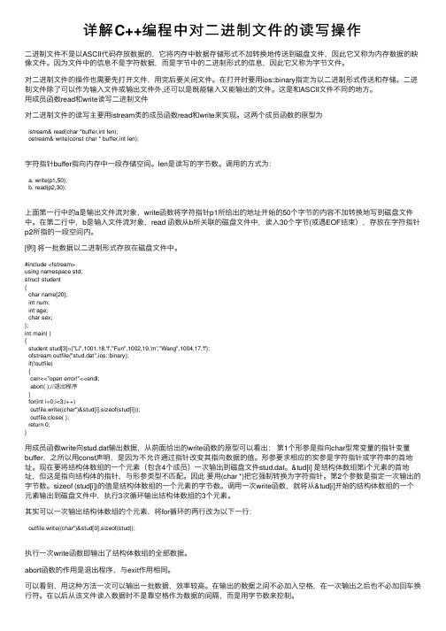
详解C++编程中对⼆进制⽂件的读写操作⼆进制⽂件不是以ASCII代码存放数据的,它将内存中数据存储形式不加转换地传送到磁盘⽂件,因此它⼜称为内存数据的映像⽂件。
因为⽂件中的信息不是字符数据,⽽是字节中的⼆进制形式的信息,因此它⼜称为字节⽂件。
对⼆进制⽂件的操作也需要先打开⽂件,⽤完后要关闭⽂件。
在打开时要⽤ios::binary指定为以⼆进制形式传送和存储。
⼆进制⽂件除了可以作为输⼊⽂件或输出⽂件外,还可以是既能输⼊⼜能输出的⽂件。
这是和ASCII⽂件不同的地⽅。
⽤成员函数read和write读写⼆进制⽂件对⼆进制⽂件的读写主要⽤istream类的成员函数read和write来实现。
这两个成员函数的原型为istream& read(char *buffer,int len);ostream& write(const char * buffer,int len);字符指针buffer指向内存中⼀段存储空间。
len是读写的字节数。
调⽤的⽅式为:a. write(p1,50);b. read(p2,30);上⾯第⼀⾏中的a是输出⽂件流对象,write函数将字符指针p1所给出的地址开始的50个字节的内容不加转换地写到磁盘⽂件中。
在第⼆⾏中,b是输⼊⽂件流对象,read 函数从b所关联的磁盘⽂件中,读⼊30个字节(或遇EOF结束),存放在字符指针p2所指的⼀段空间内。
[例] 将⼀批数据以⼆进制形式存放在磁盘⽂件中。
#include <fstream>using namespace std;struct student{char name[20];int num;int age;char sex;};int main( ){student stud[3]={"Li",1001,18,'f',"Fun",1002,19,'m',"Wang",1004,17,'f'};ofstream outfile("stud.dat",ios::binary);if(!outfile){cerr<<"open error!"<<endl;abort( );//退出程序}for(int i=0;i<3;i++)outfile.write((char*)&stud[i],sizeof(stud[i]));outfile.close( );return 0;}⽤成员函数write向stud.dat输出数据,从前⾯给出的write函数的原型可以看出:第1个形参是指向char型常变量的指针变量buffer,之所以⽤const声明,是因为不允许通过指针改变其指向数据的值。
- 1、下载文档前请自行甄别文档内容的完整性,平台不提供额外的编辑、内容补充、找答案等附加服务。
- 2、"仅部分预览"的文档,不可在线预览部分如存在完整性等问题,可反馈申请退款(可完整预览的文档不适用该条件!)。
- 3、如文档侵犯您的权益,请联系客服反馈,我们会尽快为您处理(人工客服工作时间:9:00-18:30)。
The generic files call some externally defined C functions that are
specific for the development environment, such as the PlotWaveform
32 bit fetch = -2,147,484,468 to 2,147,484,467
For devices like the NI 5911 with up to 21 bits of resolution, you will need
to fetch 32-bit data. Fetching 8-bit data would be away resolution!
stored on onboard memory. Refer to the sample width example for more details
on this feature.
File Locations and Responsiblities:
Each NI-SCOPE example for CVI includes a directory of files specific to
displayed on the front panel of this example.
Another feature of this example is the while loop surrounding only Initiate
Acquisition and Fetch. This is the most efficient way to repeatedly acquire
The driver always fetches binary data from the digitizer using DMA.
Typically you will fetch scaled data, which is a double (8 byte) floating
point number in units of volts. However, it is faster to fetch the binary
data values constant for each fetch type, regardless of the device resolution,
as follows:
8 bit fetch = -128 to 127
16 bit fetch = -32,768 to 32,767
For devices like the NI 5620 and NI 5122 with 14 bits of reslution, there is
rarely a reason to fetch anything but 16-bit data.
For some devices it is possible to change the width of the data before it is
Finally, notice that the binary data size parameter changes which Fetch
function is used. The only difference is the size of the binary data
returned from the driver. For 8-bit devices such as the NI 5102 and NI
that example. In addition, each example project includes a generic .c
and .h file located in the cvi\samples\niScope\common directory. These
generic files include all the NI-SCOPE specific programming, and they are
5112, there is rarely a reason to fetch anything but 8-bit data. If you
fetch 16- or 32-bit data from these devices, the data is shifted left and
the least order 8 or 16 bits are always zero. This makes the min and max
function that displays the acquired waveform. In CVI, these functions
are located in the .c file for the example. This file implements the
GUI using CVI controls.
Example: Binary Acquisition
Recommended Input Signal: 100 kHz, 8 Vpp, sine wave
Devices Supported: Refer to NI Example Finder
CVI Description:
This example demonstrates fetching binary data instead of scaled data.
waveforms. However, the configuration of the digitizer, such as the
sampling rate and vertical range, cannot be changed while the example is
running.
data, which is a signed 8-, 16-, or 32- bit integer. Then you can scale
the data to voltage using the gain and offset scaling parameters returned
by the Fetch function in the wfmInfo structure. The scaling factors are
