SSIN振动时效说明书
振动时效设备安全技术操作规程

振动时效设备安全技术操作规程振动时效设备是一种常见的试验设备,在物理、化学、材料等领域广泛应用。
为了确保工作安全和设备正常运行,有必要制定一份安全技术操作规程。
以下为振动时效设备安全技术操作规程:一、设备操作前的准备工作1.1 操作人员必须熟悉振动时效设备的工作原理、操作方法以及安全操作规程。
1.2 振动时效设备应安装在平稳、牢固的地面上,并确保设备周围无障碍物。
1.3 确保振动时效设备的供电电源和地线正常接地,设备的安全开关和保护装置完好有效。
1.4 确保试验样品的安装和固定正确可靠。
二、设备操作时的安全注意事项2.1 操作人员应佩戴个人防护用品,如安全帽、防护眼镜、耳塞/耳罩、防护手套和防滑鞋等。
2.2 操作人员禁止戴长发、戴手饰等可能引起事故的物品。
2.3 操作前应检查设备安全开关是否处于停止状态,确保设备在操作前没有任何异常。
2.4 操作人员在启动振动时效设备前,应当确保设备工作区域内没有人员站立或经过。
三、振动时效设备的操作方法3.1 操作人员应按照设备的使用说明书正确操作设备,不得随意更改设备参数或进行不正当操作。
3.2 操作人员应定期检查振动时效设备的运行状态,如设备有异常情况,应立即停机排除故障。
3.3 操作人员应严格按照设备的负荷限制操作,不得超过设备的额定工作范围。
3.4 操作人员应合理安排振动试验的时间和频率,不得长时间连续运行设备。
四、设备维护和检修4.1 振动时效设备应定期进行保养和维护,设备维护应由专业技术人员进行,不得由非相关人员进行操作。
4.2 设备的保养和维护应按照设备制造商的要求进行,不得随意更改和调整设备。
4.3 在设备维护和检修期间,应将设备关闭,并断开电源,以确保操作人员的安全。
4.4 设备维护和检修后,应进行试验运行、安全检测,确保设备的正常运行。
五、应急措施和事故处理5.1 在设备操作中,如发现设备异常或试验样品出现故障,应立即停机,并通知设备维护人员进行处理。
示乐思 探头 数据手册说明书
SIGLENT探头数据手册CN01ASIGLENT探头数据手册无源探头1X/10X 1X/10X 1X/10X 1X/10X10X 10X 10X 10XSIGLENT探头数据手册10X单端有源探头1.5GHz 1GHz 1GHz2.5GHzSIGLENT探头数据手册差分有源探头>2.5 GHzSIGLENT探头数据手册电流探头DC-200kHz DC-1MHz DC-300kHz DC-300kHzSIGLENT探头数据手册DC-50MHz DC-100MHz DC-12MHz DC-5MHzSIGLENT探头数据手册23℃ ,60%RH, 附近无载流线,被测导线穿过中心测试,负载阻抗1MΩSIGLENT探头数据手册高压差分探头70MHz 100MHz 70MHz 100MHzSIGLENT探头数据手册50MHz 50MHzSIGLENT探头数据手册高压探头DC-40MHzSIGLENT探头数据手册逻辑探头16 16 16SIGLENT探头数据手册近场探头300kHz to 3 GHz 300kHz to 3 GHz 300kHz to 3 GHz 300kHz to 3 GHzSIGLENT 探头数据手册关于鼎阳鼎阳科技(SIGLENT )是通用电子测试测量仪器领域的行业领军企业。
同时,也是通用电子测试测量仪器行业第一家A 股上市公司。
2002年,鼎阳科技创始人开始专注于示波器研发,2005年成功研制出第一款数字示波器。
历经多年发展,鼎阳产品已扩展到数字示波器、手持示波表、函数/任意波形发生器、频谱分析仪、矢量网络分析仪、射频/微波信号源、台式万用表、直流电源、电子负载等基础测试测量仪器产品,是全球极少数能够同时研发、生产、销售数字示波器、信号发生器、频谱分析仪和矢量网络分析仪四大通用电子测试测量仪器主力产品的厂家之一,是这四大主力产品领域唯一一个国家级重点“小巨人”企业。
公司总部位于深圳,在美国克利夫兰和德国奥格斯堡成立了子公司,在成都成立了分公司,产品远销全球80多个国家和地区,SIGLENT 已经成为全球知名的测试测量仪器品牌。
HK2000系列全自动振动时效装置操作说明

LM-10Y液晶系列全自动振动时效使用说明书济南利美机电科技有限公司目录一、概述-----------------------------------------------(1)二、主要技术性能---------------------------------------(1)三、使用条件-------------------------------------------(2)四、操作配置说明---------------------------------------(2)五、运行准备-------------------------------------------(4)六、操作步骤及方法-------------------------------------(8)1、定时全自动运行模式------------------------------(8)2、全自动运行模式----------------------------------(8)3、半自动运行模式----------------------------------(9)4、手动运行模式------------------------------------(9)七、时效时间的控制-------------------------------------(10)八、注意事项-------------------------------------------(11)1、怎样判断对零件的时效效果是否达到时效要求?------(11)2、加速度过大,曲线打印不完整怎么办?--------------(11)3、扫描过程中发现了共振峰但不停机怎么办?----------(11)4、工件已振动,但无加速度值显示怎么办--------------(11)5、电流太大怎么办?--------------------------------(12)6、什么是飞车,飞车的危害是什么?-------------------(12)7、什么是飞车保护?-------------------------------(12)8、液晶屏上显示转速信号故障怎么办?----------------(12)9、开机后液晶屏和电源指示灯都不亮怎么办?----------(12)10、无转速显示或出现飞车保护标志怎么办?----------(13)11、怎样更换测速板?-------------------------------(13)12、打印机不打印怎么办?--------------------------(13)13、开机后电机不转怎么办?-------------------------(14)14、电机碳刷火花大怎么办?-------------------------(14)15、偏心轮的偏心距调不动怎么办?-------------------(14)16、激振器的维护与保养。
振动时效技术要求

2. 工件及激振装置的放置 2.1. 为了便使工件在振动过程中始终处于自由状态,应采用橡胶垫(如橡胶轮胎等)作支撑。 2.2. 激振装置应刚性地固定在工件刚度较强或振幅较大处,不准固定在大而薄的平面等刚性较
差的部位,固定激振装置处应平整。
率不超过额定功率的 80%。 4.3. 振前进行扫频,记录振幅频率(a-t)曲线。 4.4. 主振工件,记录振幅时间(a-t)曲线。 4.5. 起振后振幅时间(a-t)曲线上的振幅上升,然后变平或上升后下降然后再变平,从变平开
始稳定 3~5min 为振动截止时间。 4.6. 振后进行扫频,记录振幅频率(a-n)曲线。 4.7. 必要时可作多点激振处理,也可用附振频率(即主振频率以外的各共振频率)作多频共振
曲线等。
6.操作者
由具有高中以上文化,经过专业培训合格,能严格执行工艺文件的人员担当。
7.振动时效实施
7.1 工件准备
a) 工件表面应不存在裂纹、虚焊、夹渣等严重缺陷。
b) 工件支撑采用随机附带还胶垫或废橡胶外胎在节点处作弹性支撑,应尽可能采用二点或三
点支撑,必要时也可用四点支撑,支撑应保证工件任一点不接触地面。
并保证其电流值低于扫频时的 3/4,否则应减少加速度值开激振力,在线打印加速度-时间
曲线。
b) 观察加速度值,若有上升后最终变平,则认为时效效果基本达到,如 20min 尚未有上升变
化,则应提高加速度值或激振力。
c) 继续对附振频率进行时效处理。
d) 振后自动扫描,记录α-n 曲线。
7.3.3 振动时效效果评定
3.4. 必要时可通过调整支撑点、激振点和拾振点的位置来激起较多的振型。 3.5. 测定 1~3 个共振峰较大的频率在共振时的动应力峰值的大小,选择动应力大、频率低的共
宁波申菱门机系统使用手册
宁波申菱门机系统使用手册一、系统的构成宁波申菱门机变频调速系统硬件部分采用日本松下公司的VF-7F 的变频器,FP1-C14型可编程控制器,门机运行变速位置由双稳态开关控制。
1、变频器内部接线如下图:二、开关端子功能简述型)一、系统的构成宁波申菱门机变频调速系统硬件部分采用日本松下公司的VF-7F 的变频器,FP1-C14型可编程控制器,门机运行变速位置由双稳态开关控制。
1、变频器内部接线如下图二、开关端子功能简述1、切换开关当开关置于调试状态时,系统对外部信号不响应,按下手动开、关门按钮时,门机按要求关门或开门;当开关置于系统状态时,系统由外部信号控制,手动开、关门按钮不起作用。
2、手动关门按钮当调试切换开关置于调试状态时,按下该按钮,门机作关门运动,无论门机在何位置,停止按该按钮,门机立即停止关门运动;当调试切换开关置于系统状态时,该按钮不起作用。
3、手动开门按钮当调试切换开关置于调试状态时,按下该按钮,门机作开门运动,无论门机在何位置,停止按该按钮,门机立即停止开门运动;当调试切换开关置于系统状态时,该按钮不起作用。
4、控制输入控制输入部分包括门位置信号输入和外部控制信号输入,具体见接线图一;4-1 门位置控制信号XK1-XK4均为门位置控制信号,开、关门中XK1-XK4的具体时序图如下图所示:1)XK1、XK2、XK3、XK4的时序图开门时的时序图关门时的时序图型)2)磁性开关位置:注:开门起始区没有根据磁开关的位置定,而是根据时间设定,程序设定为1s。
4-2 外部控制信号七芯电缆中1#线为输入公共端,2#线为开门信号输入,3#线为关门信号输入。
5、控制输出输出部分如图一所示,其中七芯电缆中4#线为输出公共端,5#线为开门到位输出,6#线为关门到位输出。
6、电源输入部分三芯电缆为本控制器的电源输入电缆,黄绿线为电源接地,1#线和2#线为电源输入,其输入要求为单相交流200-240V,且电压是稳定电压。
岩土测试设备 SSG 振动线压力传感器 说明书
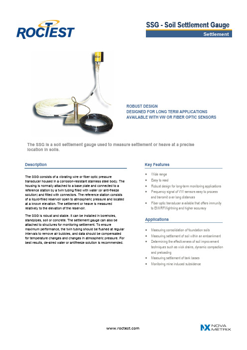
The SSG is a soil settlement gauge used to measure settlement or heave at a precise location in soils.∙ Wide range ∙ Easy to read∙ Robust design for long-term monitoring applications∙Frequency signal of VW sensors easy to process and transmit over long distances∙ Fiber optic transducer available that offers immunityto EMI/RFI/lightning and higher accuracy∙ Measuring consolidation of foundation soils∙ Measuring settlement of soil within an embankment ∙ Determining the effectiveness of soil improvementtechniques such as wick drains, dynamic compaction and preloading∙ Measuring settlement of tank bases∙ Monitoring mine induced subsidenceThe SSG consists of a vibrating wire or fiber optic pressuretransducer housed in a corrosion -resistant stainless steel body. The housing is normally attached to a base plate and connected to a reference station by a twin tubing filled with water (or anti -freeze solution) and fitted with connectors. The reference station consists of a liquid -filled reservoir open to atmospheric pressure and located at a known elevation. The settlement or heave is measured relatively to the elevation of the reservoir.The SSG is robust and stable. It can be installed in boreholes, standpipes, soil or concrete. The settlement gauge can also be attached to structures for monitoring settlement. To ensuremaximum performance, the twin tubing should be flushed at regular intervals to remove air bubbles, and data should be compensated for temperature changes and changes in atmospheric pressure. For best results, de -aired water or antifreeze solution is recommended.ROBUST DESIGNDESIGNED FOR LONG TERM APPLICATIONS AVAILABLE WITH VW OR FIBER OPTIC SENSORSKey FeaturesDescriptionApplications•Range and transducer type • Cable type and length • Twin tubing length • Saturated or not• If length of tubing exceeds 300 m, contact manufacturer for selecting adequate tubing sizeSpecificationsRoctest Ltd, 680 Birch Street St -Lambert, Quebec Canada J4P 2N3Phone +1 450 465 1113 Fax. +1 450 465 1938 ********************* Web Roctest reserves the right to make any changes in the specifications without prior noticeE50141-170404Ordering information1 With IRC -41 AV cable. Available for VW transducers only 2Calibrated accuracy of the pressure transducer.Note: Please refer to FOP data sheet for specifications of FO pressure transducers.Transducer type Vibrating wire or fiber optic Maximum overpressure 1.5 × rangeAccuracy 2 ±0.5% F.S. (±0.1% F.S. optional) Resolution0.025% F.S. (min.) Thermal drift or transducer ±0.1% F.S. / o C Reservoir PVC and ABSFluid type Water (optional antifreeze solution)Thermistor 3k Ω (see model TH -T) – with vibrating wire transducers only Twin tubing Polyethylene, 1/4 in. X 0.170 in. CableIRC -41A(P), IRC -390, CFO -3STD, CFO -9RFOptional Accessories∙ Readout instruments: MB -3TL, SENSLOG∙ Saturation kit including manual pump, pressurizing tank, manometer, hoses and fittings。
振动时效震动时效仪安全操作及保养规程

振动时效震动时效仪安全操作及保养规程一、前言振动时效震动时效仪是一种测量产品材料反应性的测试设备。
使用者在操作仪器时应注意以下安全操作细则和保养规程,以确保操作人员的安全和设备的正常运作。
二、安全操作细则1. 安装及培训1.安装前,应仔细阅读设备使用说明书。
由专业技术人员安装。
2.操作人员必须参加相关培训,熟知仪器使用方法和安全操作规程。
3.熟悉仪器的结构和性能,确保仪器的正常运行。
2. 仪器运行1.当仪器在使用时,操作人员应保持警惕,避免贴近仪器。
2.仪器运行期间,尽量避免操作人员离开工作现场。
3.防止系统误操作或误触。
3. 事故防范1.确保仪器设备操作过程中,只有具备相应资格和技能的人员方能承担。
2.如遇突发事件或经设备自身保护装置保护后未能恢复正常,应立即停机,并通知维修人员进行检查或维护。
3.不允许操作人员擅自更改系统设定及参数,更不得私自改动设备的电气、控制系统。
4. 启动前的操作1.启动前,必须确认操作人员或辅助人员是否已退出仪器设备区。
在启动仪器时,不应有人员贴近、触摸或检查仪器。
2.确定夹具装置的安装位置是否准确。
3.确认夹具装置是否已密封,安全可靠。
5. 停止前的操作1.在停止仪器前,先关停加热装置,使设备自然冷却至安全状态,再关闭操作仪器。
在停止之前,需等待仪器完全停止,切勿打开仪器的任何部件。
2.在关闭仪器前,确认操作人员或辅助人员已经离开设备工作区。
6. 报警提示当发生任何异常情况时,仪器会自动停止并发出报警提示,此时操作人员应当停止操作,找到问题的原因,并解决问题后再继续使用。
三、保养规程1.定期对仪器设备进行检查及清洁,及时消除故障及粉尘等积累以保证设备性能稳定。
2.设备每日应进行日常维护,并对设备的运行状况进行全面监测,如存在更换、调整或修理情况,需立即进行修理并记录。
3.由专业人员进行设备的全面保养、检修及定期检查维护。
在设备运行途中,长期不稳定或存在故障,应当及时通知保养人员。
申克振动二次表说明书

申克振动二次表说明书一、引言随着科技的发展,振动测量技术在各个领域得到了广泛的应用。
申克振动二次表作为一款高性能的振动测量设备,为广大用户提供了便捷、准确的振动监测解决方案。
本文将详细介绍申克振动二次表的产品特点、技术参数、安装与调试方法、操作与维护以及故障排除等方面的内容,帮助用户更好地了解和运用这款产品。
二、产品概述1.产品名称与型号申克振动二次表型号为XXXX,是一款具有高精度、高稳定性、宽量程等特点的振动测量仪器。
2.产品用途与特点申克振动二次表主要用于各种机械设备的振动监测,适用于振动频率范围广泛、振动幅度较大的场合。
产品特点如下:(1)高精度:测量精度高达±1%;(2)高稳定性:具有良好的抗干扰能力,能适应各种恶劣环境;(3)宽量程:可测量振动加速度、振动速度、振动位移等多种振动参数;(4)智能化:具有自动校准、自动滤波等功能;(5)易操作:采用人性化设计,操作简便。
三、技术参数1.主要技术指标(1)振动加速度测量范围:0.1mg~100g;(2)振动速度测量范围:0.1mm/s~1000mm/s;(3)振动位移测量范围:0.01μm~100μm;(4)频率测量范围:10Hz~1kHz;(5)输出信号:4-20mA、RS-485等。
2.适用范围申克振动二次表适用于各类旋转机械、往复式机械以及其他振动系统的振动监测。
四、安装与调试1.安装要求(1)振动二次表应安装在易于操作和观察的位置;(2)安装时,确保振动二次表与传感器的连接可靠;(3)避免振动二次表受潮、受热、受冻、遭受机械冲击等;(4)为保证测量精度,振动二次表与传感器之间的距离应适当。
2.调试方法(1)接通电源,打开振动二次表;(2)调整零点平衡旋钮,使显示值为零;(3)用标准振动信号发生器输入规定的信号,检查振动二次表的测量范围和精度;(4)如发现问题,根据实际情况进行调整。
五、操作与维护1.操作步骤(1)开启振动二次表:接通电源,按下开机键;(2)选择测量参数:通过菜单键选择振动加速度、振动速度或振动位移等;(3)调整量程:根据实际需要,调整量程旋钮;(4)调整滤波器:根据振动信号特点,选择合适的滤波器类型和截止频率;(5)查看测量数据:通过显示屏幕查看实时测量数据。
振动时效仪操作规程

时效振动仪操作规程1.本设备应有专人进行保管与操作,操作者应严格按本规程进行操作。
2.使用前,首先检查电机运转是否正常、控制箱工作是否正常。
3.根据的大小尺寸,将激振器装夹在工件的中央或一端处。
4.按使用说明书将装置各部分用电缆接好,预热5分钟。
5.按工件的振动时效工艺卡要求,将激振器用弓形卡具卡紧在工件的共振峰处,传感器吸紧在工件的另一共振峰处。
6.打开主控箱电源开关,若液晶屏幕上滚动显示装置的操作步骤,说明主控箱内微机工作正常。
否则工作不正常。
7.按运行键开始工作,并对工件进行振动前扫描,若工艺参数合适则装置将自动继续进行第二步的振动时效处理和第三部振动时效效果的检测,若工艺参数不合适,液晶屏上将显示不合适的原因并给出修正方案,操作者需按屏幕上显示的步骤对工艺参数进行修正,修正完后关机。
然后再开机按“运行”键进行振动时效处理。
8.对于第一次时效处理的工作,也可以采用手动操作方式,按“上升”键为手动控制,电机转速缓慢升速;每按一次改变一种升速速度。
若停止升速按“下降”键即可,降速按相反方式操作。
当电机转速和工件固有频率一致时,工件发出共鸣声,工件产生共振,这时停止电机升速;将工作的支撑、激振器、传感器的位置调整好后,重新开机,整套装置将自动完成对工件的第一次扫描、并打印振动时效处理过程中数据和变化曲线。
及时效效果(OK).9.检测对工件的振动时效效果是否达到JB/T5692-91标准规定的要求,若没有达到,将再振动一次。
10.使用完后,将控制开关关掉,将激振器、传感器从工件上卸下和备件一起放在指定设备保管处;注意保持时效仪的清洁、干净,以防损坏。
Endevco 256HX 小型震动传感器说明书
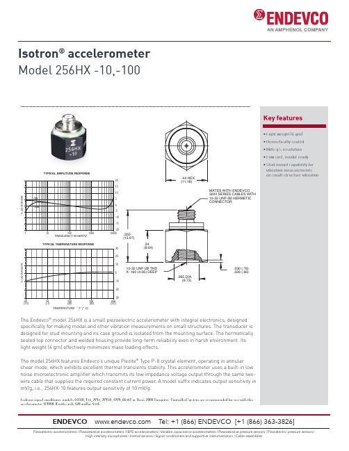
Isotron ® accelerometer Model 256HX -10,-100Key features• Light weight (4 gm)• Hermetically sealed • Milli-g’s resolution • Low cost, modal ready • Stud mount capability for vibration measurements on small structure vibrationThe Endevco ® model 256HX is a small piezoelectric accelerometer with integral electronics, designedspecifically for making modal and other vibration measurements on small structures. The transducer is designed for stud mounting and its case ground is isolated from the mounting surface. The hermetically sealed top connector and welded housing provide long-term reliability even in harsh environment. Its light weight (4 gm) effectively minimizes mass loading effects.The model 256HX features Endevco’s unique Piezite ® Type P-8 crystal element, operating in annular shear mode, which exhibits excellent thermal transients stability. This accelerometer uses a built-in low noise microelectronic amplifier which transmits its low impedance voltage output through the same two-wire cable that supplies the required constant current power . A model suffix indicates output sensitivity in mV/g, i.e., 256HX-10 features output sensitivity of 10 mV/g.Endevco signal conditioner models 4416B, 133, 2793, 2775B, 4999, 6634C or Oasis 2000 Computer-Controlled System are recommended for use with this accelerometer (4990A-X with cards 428 and/or 433).-20-15-10-505101520FREQUENCY IN HERTZTYPICAL AMPLITUDE RESPONSE-30-20-100102030-6020100180260% D E V I A T I O NTEMPERATURE °F (°C)TYPICAL TEMPERATURE RESPONSE(-51)(-7)(38)(82)(127).030 (.76).026 (.66)Isotron® accelerometerModel 256HX -10,-100SpecificationsThe following performance specifications conform to ISA-RP-37.2 (1964) and are typical values, referenced at +75˚F (+24˚C), 24 Vdc supply, 4 mA, and 100 Hz, unless otherwise noted. Calibration data, traceable to National Institute of Standards and Technology (NIST), is supplied.Dynamic characteristics Units -10 -100Range g±500±50Voltage sensitivity (±10%)mV/g 10 100Frequency response See typical amplitude responseResonance frequency (typical)kHz2525Amplitude response (±10%) Hz 1 to 10 000 1 to 10 000Temperature response See typical curve-67°F (-55°C) max %-15-15+257°F (+125°C) max %+5+5Transverse sensitivity % ≤ 5 ≤ 5Amplitude linearity % ≤ +1 to full scale ≤ +1 to full scaleOutput characteristicsOutput polarity Acceleration directed inot base of unit produces positive outputDC output bias voltage, typical Vdc +12.3 to +13.5 +12.3 to +13.5-67°F to +257°F (-55°C to +125°C)Vdc +7.0 to +16.0 +7.0 to +16.0Output impedanceΩ ≤ 200 ≤ 200Output connection See connection diagramFull scale output voltage V±5±5Residual noise (5 Hz to 10 kHz, broadband)typical equiv. g rms0.0010.0003maximum equiv. g rms≤ 0.002 ≤ 0.0005Overload recoveryμsec≤ 45 ≤ 45Grounding Signal ground connects to inner case, and isolated from outer housing Power requirementSupply voltage Vdc +23 to +30 +23 to +30Supply current mA +2 to +20 +2 to +20Warm-up time (to within 10% of final bias) sec 8 8Stray voltage output (with 10 V rms at100 Hz applied to the mounting surface) equiv. g ≤ 0.001 ≤ 0.001Environmental characteristicsTemperature range -67˚F to +257˚F (-55˚C to +125˚C)Humidity Hermetically sealedSinusoidal vibration limit g1*******Shock limit g2*******Base strain sensitivity equiv. g /μ strain 0.0008 0.0008Thermal transient sensitivity equiv. g /˚F (/˚C) 0.5 (0.9) 0.5 (0.9)Electromagnetic sensitivity equiv. g rms/gauss 0.0001 0.00001Physical characteristicsDimensions See outline drawingWeight oz (gm) 0.14 (4.0) 0.14 (4.0)Case material Titanium alloy connector, stainless steel inner housing, anodized aluminum outer case Connector Coaxial, 10-32 thread mates with Endevco 3000 series cableMounting Internal 10-32 UNF-2B for stud mountingMaximum mounting torque lbf-in (Nm) 12 (1.4) 12 (1.4)Supplied calibrationSensitivity mV/gMaximum transverse sensitivity %Frequency response% 20 Hz to 10 kHz 20 Hz to 10 kHzdB 10 kHz to 40 kHz 10 kHz to 40 kHzIsotron® accelerometerModel 256HX -10,-100Contact AccessoriesT el: +1 (866) ENDEVCO[+1 (866) 363-3826]Notes:1. Maintain high levels of precision and accuracy using Endevco’s factory calibration services. Call Endevco’s insidesales force at 866-ENDEVCO for recommended intervals, pricing and turn-around time for these services as wellas for quotations on our standard products.。
HK2000系列全自动振动时效装置操作使用说明书
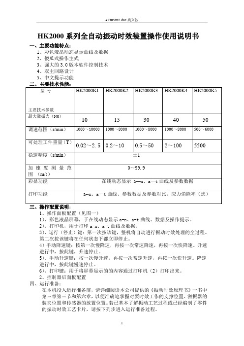
HK2000系列全自动振动时效装置操作使用说明书一、主要功能特点:1、彩色液晶动态显示曲线及数据2、傻瓜式操作主式3、强大的3.0版本软件控制技术4、双主回路设计5、中文提示功能1、操作面板配置(见图一)1)、彩色液晶屏幕,于在线动态显示a-n、a-t曲线、数据及操作提示。
2)、打印机,用于打印a-n、a-t曲线及数据。
3)、运行(停止)键:第一次按该键,整机将自动进行振动时效处理的全过程。
第二次按该键将在任何状态下都立即停止。
4)手动降速键:按第一次慢降速,再按一次常速降速,再按一次快降速。
升速进行中,按此键,升速停止。
5)、手动升速键:按一次慢升速,再按一次常速升速,再按一次快升速。
降速进行中,按此键慢速停止。
6)、打印键:用于将屏幕显示的的内容通过打印机(2)打印出来。
2、控制器后面板配置四、运行准备:在本机投入运行准备前,请详细阅读本公司提供的《振动时效原理书》一书中第三章第三节和第六章,以便准确地掌握对要时效工作的支撑位置、激振器的装夹位置和传感器的放置位置。
若已基本了解振动工艺过程或已经编制了零件的振动时效工艺卡片,请按下列步进入运行准备过程。
1、按工艺要求用橡胶垫(或废旧轮胎、方木等)将工件支撑位起来,橡胶垫的支撑位置应尽量靠近工件共振时的节线处。
2、将激振器用两个弓型卡具装夹位置应尽量靠近工作件共振时的波峰处,弓形卡具要拧紧以免卡具松动,激振器掉下来。
3.传感器拧上磁座后,将其吸紧在工件共振时的波峰处,因工件共振时有多个波峰,所以传感器和激振器尽量不要放在工件的同一个波峰处。
4.用五芯电缆将激振器和控制器连接起来。
5.用屏蔽线将传感器和控制器连接起来。
6.根据被处理工件的重量及尺寸大小,粗略估计并调整激振器的偏心距。
调整方法如下(见图3)。
先将内六方扳手从偏心距调孔④处插下,再把一字型螺丝刀插到偏心距轴调节槽⑥内并旋转偏心轴当旋转到某一位置时,即被内六方扳手卡住,这时将内六方扳手抬起一点再用螺丝刀稍微旋转一点偏心轴,并将内六方扳手插下同时一定要确认内六方扳手要正好插进偏心块上的锁紧螺母的内六方内。
华云豪克能振动时效仪使用说明书
华云豪克能振动时效仪使用说明书华云豪克振动时效仪是一种测试材料受振动疲劳性能的仪器,可以用来测试各种材料在振动环境下的疲劳寿命和损伤程度。
下面我们来介绍一下该仪器的使用方法。
一、仪器的技术参数
1. 振动频率:0-200Hz;
2. 加速度范围:0.1到200m/s²;
3. 疲劳台模式:模拟全振动;
4. 控制方式:全数字控制;
5. 通道数:8个;
6. 加速度最大值:50g;
7. 测量范围:20mV/g到100000mV/g。
二、仪器的使用步骤
1. 开始之前,应将所有材料测定后装夹到试验台上,并调整试验台斜度,使其与整个仪器垂直,确保测试精度;
2. 按照操作说明打开电源开关并设置测试参数;
3. 在测试前,应对仪器进行预热和空载振动测试,以确保系统正常工作;
4. 调整振动频率和加速度,保证测试数据的准确性;
5. 执行测试程序并记录数据;
6. 分析和处理数据,得到测试结论。
三、注意事项
1. 禁止使用老化或损坏的材料进行测试;
2. 测试前应保证试验台清洁干燥;
3. 测试时应保证试验台稳定,防止干扰测试结果;
4. 操作注意电源和数据接口的连接和拔插;
5. 测试结束后应对仪器进行清理和维护。
总之,华云豪克振动时效仪是一种高性能的测试仪器,能够准确测试各种材料在振动环境下的疲劳寿命和损伤程度,在材料科学和工程领域具有重要的应用价值。
在使用过程中,要严格按照操作步骤和注意事项进行操作,确保测试数据的准确性和仪器的正常运行。
科学实验设备:S CIENTIFIC 波动实验仪说明书
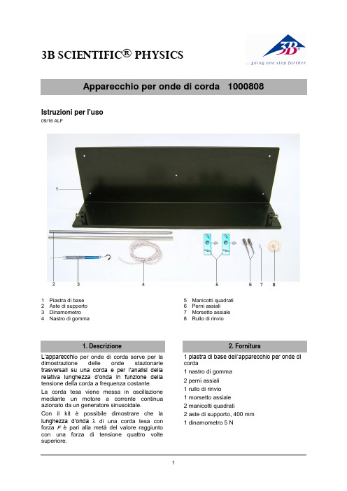
3B SCIENTIFIC ® PHYSICS1Istruzioni per l'uso09/16 ALF1 Piastra di base2 Aste di supporto3 Dinamometro 4Nastro di gomma5 Manicotti quadrati6 Perni assiali7 Morsetto assiale 8Rullo di rinvioL’apparecchi o per onde di corda serve per la dimostrazione delle onde stazionarie trasversali su una corda e per l’analisi della relativa lunghezza d’onda in funzione della tensione della corda a frequenza costante.La corda tesa viene messa in oscillazione mediante un motore a corrente continua azionato da un generatore sinusoidale.Con il kit è possibile dimostrare che la lunghezza d’onda di una corda tesa con forza F è pari alla metà del valore raggiunto con una forza di tensionequattro volte superiore.1 piastra di base dell’apparecchio per onde di corda1 nastro di gomma2 perni assiali 1 rullo di rinvio 1 morsetto assiale 2 manicotti quadrati2 aste di supporto, 400 mm 1 dinamometro 5 N3B Scientific GmbH ▪ Rudorffweg 8 ▪ 21031 Amburgo ▪ Germania ▪ Con riserva di modifiche tecniche © Copyright 2016 3B Scientific GmbHPer l'esecuzione degli esperimenti sono inoltre necessari i seguenti apparecchi:1 motore a corrente continua 1001041 1 generatore sinusoidale 1001038 1 trasformatore @230 V 1000866 o1 trasformatore @115 V 1000865 Cavo per esperimenti3.1 Struttura∙ Realizzare una struttura sperimentalecome indicato in Fig. 1.∙ Inserire e fissare il motore a correntecontinua nell’attacco sinistro per le aste di supporto.∙ Avvitare l’una all’altra le aste di supporto,inserirle nell’attacco destro e bloccarle. ∙ Fissare i manicotti universali all'asta disupporto.∙ Infilare il rullo di rinvio nel perno assiale,assicurarlo con il morsetto assiale e fissare il tutto al manicotto universale inferiore. ∙ Fissare il secondo perno assiale almanicotto universale superiore e agganciare il dinamometro.∙ Fissare il nastro di gomma al motore acorrente continua, farlo passare sotto alrullo di rinvio portandolo verso l’alto e agganciarlo al dinamometro.∙Regolare l’altezza del rullo di rinvio in modo che il nastro di gomma scorra parallelamente alla piastra di base.∙Collegare il motore a corrente continua con il generatore sinusoidale e allacciare quest’ultimo al trasformatore.3.2 Esecuzione∙ Posizionare gli interruttori S2 e S3 delgeneratore sinusoidale su Generatore (a destra).∙ Tendere la corda mediante il dinamometro. ∙ Impostare la frequenza del generatoresinusoidale in modo che si formino 4 ventri di oscillazione. Eseguire la regolazione fine con il regolatore di ampiezza.La lunghezza d’onda è ora pari alla metà della lunghezza della corda.∙ Spostare il dinamometro verso l’alto lun goil supporto stativo, fino a quadruplicare il valore della tensione della corda.Sulla corda si formano ora 2 ventri di oscillazione e la lunghezza d’onda è pari alla lunghezza della corda.I seguenti parametri forniscono buoni risultati: frequenza 42-43 Hz, tensione iniziale della corda 0,5 NFig. 1 Struttura sperimentale。
330400 330425 振动传感器 使用指南说明书

DescriptionThese accelerometers are intended for critical machineryapplications where casing acceleration measurements arerequired, such as gear mesh monitoring. The 330400 isdesigned to address the requirements of AmericanPetroleum Institute Standard 670 for accelerometers. Itprovides an amplitude range of 50 g peak and a sensitivity of100 mV/g. The 330425 is identical except it provides a largeramplitude range (75 g peak) and a sensitivity of 25 mV/g.If housing measurements are being made for overallprotection of the machine, thought should be given tothe usefulness of the measurement for eachapplication. Most common machine malfunctions(imbalance, misalignment, etc.) originate at the rotorand cause an increase (or at least a change) in rotorvibration. In order for any housing measurementalone to be effective for overall machine protection, asignificant amount of rotor vibration must be faithfullytransmitted to the bearing housing or machinecasing, or more specifically, to the mounting locationof the transducer.In addition, care should be exercised in the physicalinstallation of the transducer. Improper installation can resultin a degradation of the transducer’s performance, and/ orthe generation of signals which do not represent actualmachine vibration. Integration of the output to velocity canworsen this. Extreme caution should be exercised ifintegrating to velocity. For high quality velocitymeasurements the 330500 Velomitor Sensor should be used.Upon request, we can provide engineering services todetermine the appropriateness of housing measurements forthe machine in question and/or to provide installationassistance.330400and330425AccelerometerAcceleration TransducersDatasheetBently Nevada Machinery Condition Monitoring141638Rev.YSpecificationsParameters are specified from +20 to +30 °C (+68 to +86 °F) and 100 Hz unless otherwise indicated.Operation outside the specified limits mayresult in false readings or loss of machinemonitoring.Electrical330400Sensitivity10.2 mV/m/s2 (100 mV/g) ±5%.Acceleration range 490 m/s2(50 g) peak overall acceleration within the 10 Hz to 15 kHz frequency span. Vibration at frequencies above 15 kHz, especially at the transducers resonance will significantly decrease this range.AmplitudeLinearity±1% to 490 m/ s2(50 g) peak.BroadbandNoise Floor(10 Hz to 15kHz)0.039 m/s2 (0.004 g) rms. 330425Sensitivity 2.5 mV/m/s2 (25 mV/g) ±5%.Acceleration Range 735 m/s2 (75 g) peak overall acceleration within the 10 Hz to 15 kHz frequency span. Vibration at frequencies above 15 kHz, especially at the transducer’s resonance, will significantly decrease this range.AmplitudeLinearity±1% to 735 m/s2 (75 g) peak. BroadbandNoise Floor (10 Hz to 15 kHz)0.098 m/s2 (0.01 g) rms.Both Units(shipped prior Bently Nevada recommendsinstalling with the Mountingbase to minimize base strainsensitivity for serial numbersNOT preceded by the letter“G”.305 metres (1000 ft) with noEnvironmental LimitsOperatingand storagetemperature-55°C to +121°C (-67°F to +250°F)Shock Survivability 49,050 m/s2 (5000 g) peak, maximum.Relative humidity 100% condensing, non-submerged. Case is hermetically sealed.Magnetic Field Susceptibility <2.21 mm/s2/gauss (225 mg/gauss) [50 gauss, 50-60Hz].IP Rating Equivalent to an IP 68 (Dust tight and watertight). Please note that this is for the sensor only and does not apply to the cable.PhysicalWeight (nocable)99 g (3.5 oz), typicalDiameter23 mm (0.93 in).Height59 mm (2.3 in), including mountingstud.Connector3-pin MIL-C-5015 Receptacle316L stainless steelMountingSurface32 minch rms.MountingTorque 4.1 N·m (3.0 ft·lb).Case Material316L stainless steelWeight (nocable)100 g (3.5 oz), typicalMountingAngle Any orientationCompliance and CertificationsFCCThis device complies with part 15 of theFCC Rules. Operation is subject to thefollowing two conditions:l This device may not cause harmfulinterference.l This device must accept anyinterference received, includinginterference that may causeundesired operation.EMCEMC Directive 2014/30/EURoHSRoHS Directive 2011/65/EU Maritime330400 and 330425 onlyABS 2009 Steel Vessels Rules1-1-4/7.7,4-8-3/1.11.1,4-9-7/13Hazardous Area ApprovalsFor the detailed listing of country and productspecific approvals, refer to the Approvals QuickReference Guide (108M1756) available from.CSA/NRTL/C190501 (Agency Approval Options 01 through 04)Intrinsically Safe Ex ia IIC T4:Class I, Div 1, Groups A, B, C, D.Class II, Group E, F and GClass IIIAEx ia IIC T4:Class I, Div 1, Groups A, B, C, D;Class II, Groups E, F, GClass IIIInstall per drawing 167536T4 @ -40 °C ≤ Ta ≤ +100 °C(-40 °F ≤ Ta ≤ +212 °F)IntrinsicallySafe andNon-IncendiveEx nL IIC T4Class I, Division 2, Groups A, B, C and DAEx nA T4Class I, Division 2, Groups A, B, C and DInstall per drawing 167536T4 @ -40 °C ≤ Ta ≤ +100 °C(-40 °F ≤ Ta ≤ +212 °F)330400,330425Ex ia IIC T4AEx ia IIC T4Class I, Div 1 Groups A, B, C and DClass II, Groups E, F, and GClass IIIT4 @ -40°C ≤ Ta ≤ 100°CInstall per dwg 167538330500Ex ia IIC T4AEx ia IIC T4Class I, Division 1, Groups A, B, C and DClass II, Groups E, F, GClass IIIInstall per dwg 167537T4 @ -40°C ≤ Ta ≤ 100°CEx nL IIC T4AEx nA IIC T4Class I, Div 2, Groups A, B, C, DInstall per dwg 167537T4 @ -40°C ≤ Ta ≤ 100°C330525Ex ia IIC T4AEx ia IIC T4Class I, Division 1, Groups A, B, C and DClass II, Groups E, F, GClass IIIT4 @ -40°C ≤ Ta ≤ 100°CEx nL IIC T4AEx nA IIC T4Class I, Div 2, Groups A, B, C, DInstall per dwg 167539T4 @ -40°C ≤ Ta ≤ 100°CATEX/IECEx190501, 330400, 330425, 330500, 330525190501II 1 GEntity Parameters Ex ia IIC T4 GaII 3 DEx na IIC T4 GcEx tc III T130°C DcT4@ Ta = -55°C to 121°CZone 0/1 Zone 2 Ui= 30V Ui= 30V Ii= 200mA Ii= 200mA Pi= 0.75W Pi= 1.14W Ci-27.2nFLi= 0330400, 330425, 330500, 330525Entity ParametersII 1 GEx ia IIC T4 GaII 3 DEx na IIC T4 GcEx tc III T130°C DcT4@ Ta = -55°C to 121°CZone 0/1 Zone 2Ui= 28V Ui= 28VIi= 150mA Ii= 150mAPi= 0.84W Pi= 1.26WCi-10.8nFLi= 0Hazardous Area Conditions ofSafe UseATEX/IECExZone 0/1:Equipment must be connected to equipment,which meets the abovelisted entity parameters.The cables type A or B (in compliance with EN60079-25) must respect the cable parameterslisted with the entity parameters.Zone 2 :The supply electrical parameters shall notexceed the values mentioned in the tablesabove.Ordering InformationFor the detailed listing of country and productspecific approvals, refer to the Approvals QuickReference Guide (108M1756) available from.330400 Accelerometer330425 AccelerometerPart Number-AA-BBA: Mounting Thread Option0 1¼-28 UNF integral stud0 2M8 X 1 integral studB: Agency Approval Option0 0None0 5Multiple approvals (CSA, ATEX, IECEx,) Interconnect CablesPart Number-AAA: Cable Length Option in feetFor the cables listed below, order inincrements of 1.0 ft (305 mm). Examples:1 5 = 15 ft (4.57 m)2 0 = 20 ft (6.10 m)The following are standard lengthsNon-standard/custom lengths can alsobe ordered at additional cost.1305393-conductor shielded 18 AWG (1.0mm2) cable with 3-socket plug andfluorosilicone elastomer boot at oneend, terminal lugs at the other end.Minimum length of 2.0 ft (0.6 m),maximum length of 99 ft (30 m). Amanual is available to assist withinstallation of this cable (partnumber 133080-01).169253-conductor shielded 22 AWG (0.5mm2) cable with 3-socket plug atone end, terminal lugs at the otherend. Minimum length of 2.0 ft (0.6m), maximum length of 99 ft (30 m). 167103-conductor shielded 22 AWG (0.5mm2) armored cable with 3-socketplug at one end, terminal lugs at theother end. Minimum length of 3.0 ft(0.9 m), maximum length of 99 ft (30m).Accessories127088330400 and 330425 AccelerometerUser Guide00531080Mating connector for 330400 and330425 Accelerometers.37439-01For use with serial numbers NOTpreceded with the letter “G”.Mounting Base, ¼-28 to ¼-28.Reduces base strain sensitivity. 37439-02For use with serial numbers NOTpreceded with the letter “G”.Mounting Base, M8X1 to M8X1.Reduces base strain sensitivity. 43217Accelerometer Mounting Kit usedwith extension part number108576-01 and O-ring part number04290422 to allow room for the330400 or 330425 accelerometer.(See separate datasheet, document141630.)Graphs and FiguresFigure 1: Acceleration Transducer Dimensional DrawingDimensions are in millimetres (inches)Figure 2: Typical Amplitude ResponseFigure 3: 10 – 10,000 Hz Typical Amplitude Response DetailCopyright 2020 Baker Hughes Company. All rights reserved.Bently Nevada and Orbit Logo are registered trademarks of Bently Nevada, a Baker Hughes Business, in the United States and other countries. The Baker Hughes l ogo is a trademark of Baker Hughes Company. All other product and company names are trademarks of their respective holders. Use of the trademarks does not imply any affiliation with or endorsement by the respective holders.Baker Hughes provides this information on an “as is” basis for general information purposes. Baker Hughes does not make any representation as to the accuracy or completeness of the information and makes no warranties of any kind, specific, implied or oral, to the fullest extent permissible by law, including those of merchantability and fitness for a particular purpose or use. Baker Hughes hereby disclaims any and all liability for any direct, indirect, consequential or special d amages, claims for lost profits, or third party claims arising from the use of the information, whether a claim is asserted in contract, tort, or otherwise. Baker Hughes reserves the right to make changes in specifications and features shown herein, or discontinue the product described at any time without notice or obligation. Contact your Baker Hughes representative for the most current information.The information contained in this document is the property of Baker Hughes and its affiliates; and is subject to change without prior notice. It is being supplied as a service to our customers and may not be altered or its content repackaged without t he express written consent of Baker Hughes. This product or associated products may be covered by one or more patents. See /legal.1631 Bently Parkway South, Minden, Nevada USA 89423Phone: 1.775.782.3611 or 1.800.227.5514 (US only)。
库什塔依水电站引水钢岔管振动时效处理
库什塔依水电站引水钢岔管振动时效处理俞永辉【摘要】The principle and process of Vibrating Stress Relief (VSR) of diversion steel bifurcated pipe in Kushitayi Hydropower Station and the effect of VSR are introduced. The problems emerged in the VSR treatment are analyzed and the precautions in VSR treatment are discussed. The ways which can improve the effect of VSR are also proposed. The practice in Kushitayi Hydropower Station shows that eliminating or homogenizing welding residual stress of diversion steel bifurcated pipe by VSR is feasible.%介绍了库什塔依水电站引水钢岔管振动时效处理的原理、工艺,以及消除焊接残余应力的效果;分析了振动时效处理过程中出现的一些问题,讨论了岔钢管振动时效处理的注意事项;提出了改善振动时效效果的途径.确认在合适的工艺条件下,采取振动时效方法消除或均化引水钢岔管的焊接残余应力是切实可行的.【期刊名称】《水力发电》【年(卷),期】2012(038)012【总页数】3页(P54-56)【关键词】钢岔管;振动时效;效果;分析;库什塔依水电站【作者】俞永辉【作者单位】新疆伊犁库克苏河水电开发有限公司,新疆伊犁 835500【正文语种】中文【中图分类】TV732.43(245)1 概况库什塔依水电站设计库容1.5亿m3,正常蓄水位1 305 m,总装机容量100 MW,年平均发电量3.50亿kW·h。
易腾克407850振动计用户手册说明书
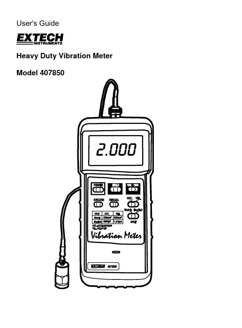
User's GuideHeavy Duty Vibration Meter Model 407850IntroductionCongratulations on your purchase of the Extech 407850 Vibration Meter. The 407850 can confirm normal vibration levels and detect abnormal levels in industrial machinery due to poor balancing, misalignment, structural compromises, and other factors. Careful use of this meter will provide years of reliable service.SpecificationsGeneral SpecificationsLCDDisplay 3-1/2digitMeasurement ranges Velocity: 0.02 to 7.87 inches/sec (0.5 to 199.9 mm/sec)Acceleration: 2 to 656 ft/s2 (0.5 to 199.9 m/s2) Frequency range 10Hz to 1KHz (frequency sensitivity meets ISO-2954)Accuracy ± (5% of reading + 2 digits)Calibration points Velocity: 50mm/sec @ 160Hz50m/s2 @ 160HzAcceleration:Sampling time One (1) second approx.Data output Isolated serial RS-232 PC InterfaceData Hold Freezes displayed readingMin/Max Memory Meter stores highest and lowest readings for later recall Auto Power OFF Meter automatically shuts off after 30 minutes of inactivity Low battery indication Battery symbol appears on the LCDPower supply 9V BatteryPower consumption 6mA DC approx.Operating Temperature 32 to 122o F (0 to 50o C)Operating Humidity Less than 80% RH2.8 x 1.3" (180 x 72 x 32mm)xDimensions Meter:7.1Probe: 0.75” (19mm) diameter x 0.83” (21mm) Weight Meter: Approx. 0.5 lbs (230g)Probe with magnetic base: 0.09 lbs (38g)Meter Description1. ProbeconnectorConnector2. RS-232Display3. LCD4. Function switches and pushbuttonscable5. Probe6. Probebase7. Magnetic8. Rubber meter jacket9. Battery compartment (on rear)Meter OperationConnecting the Probe1. Note that this meter accepts only the supplied vibration probe.2. Plug the BNC connector side of the probe into the BNC connector at the top of themeter.3. The probe can be connected to the machinery under test in three ways.a. Attach the magnetic end of the probe to a ferrous material on the equipment undertest.b. Hold the probe in place against the equipment under test manually.c. Unscrew the magnet from the probe end and use the threaded mount to connect toa screw, bolt, or stud on the equipment under test.Powering the meter1. Press the POWER button to turn the meter ON or OFF.2. The meter is equipped with an automatic power off utility that conserves battery life. Ifthe meter is left inactive for 10 minutes it will automatically turn off. The automaticpower off utility is disabled in the RECORD mode (see below).Using the Selector switches1. RMS/PEAK Switch: Select the RMS setting for RMS measurements. Select the PEAKmode for peak measurements. Peak measurements are derived from the RMS reading multiplied by 1.414.2. ACC/VEL Switch: Use this switch to select ACCELERATION measurements orVELOCITY measurements. Note that VELOCITY measurements are the most widely used measurements in industrial applications.3. METRIC/ENGLISH Switch: Use this switch to select the desired units’ convention.Zero Adjustment ProcedurePlease perform a zero calibration before each use. This will ensure the highest accuracy. Note: If the meter is used for a long period of time, temperature change and battery power loss may cause the zero calibration to drift. For continued precision measurement, the meter’s zero calibration should be readjusted.1. Set the ACC/VEL switch to the ACC (Acceleration) position.2. Insure that there is no signal present at the vibration sensor.3. Remove the protective rubber holster and open the battery cover (described below).4. Use a screwdriver to adjust the “Zero adjust VR5” potentiometer until the displayreads 0000.Data HoldTo freeze the LCD display, press the HOLD key. The 'D.H.' hold icon will appear at the top of the LCD. Press the HOLD key again to return to normal operation (the 'D.H.' hold icon will switch off).MIN / MAX RECORD / RECALL ModesTo begin capturing the Minimum (MIN) and Maximum (MAX) vibration values, press the RECORD key (‘REC’ will appear on the LCD). After taking measurements in the RECORD mode, press the RECALL button. ‘MAX’ will appear on the display along with the highest reading recorded since the RECORD button was pressed. Press the RECALL button again to view the lowest reading (‘MIN’ will appear on the display). To return to normal operation, press the RECORD button. ‘REC’ will switch off indicating that the meter has returned to the normal mode.RS-232 Serial PC InterfaceThe meter is equipped with an RS-232 serial data port (located at the top of the meter next to the probe input jack). This interface was designed to operate with the Extech DataAcquisition Software (PN 407001) and enables the user to capture, store and display readings on a PC. For more information, contact Extech or refer to the 407001 usermanual for details.Battery ReplacementWhen the 9V battery voltage falls to a critical level, the ‘LBT’ indicator appears on the LCD.Follow these steps to replace the battery:1. Remove the probe and the RS-232 cable from the meter.2. Remove the rubber boot that encases the entire meter by pulling it over the bottom ofthe meter.3. Open the battery compartment (located on the lower back of the meter) with a flat headscrewdriver.4. Replace the 9V battery, replace the compartment cover, and affix the rubber boot.WarrantyEXTECH INSTRUMENTS CORPORATION warrants this instrument to be free of defects in parts and workmanship for three years from date of shipment (a six month limited warranty applies on sensors and cables). If it should become necessary to return the instrument for service during or beyond the warranty period, contact the Customer Service Department at (781) 890-7440 ext. 210 for authorization or visit our website at (click on ‘Contact Extech’ and go to ‘Service Department’ to request an RA number). A Return Authorization (RA) number must be issued before any product is returned to Extech. The sender is responsible for shipping charges, freight, insurance and proper packaging to prevent damage in transit. This warranty does not apply to defects resulting from action of the user such as misuse, improper wiring, operation outside of specification, improper maintenance or repair, or unauthorized modification. Extech specifically disclaims any implied warranties or merchantability or fitness for a specific purpose and will not be liable for any direct, indirect, incidental or consequential damages. Extech's total liability is limited to repair or replacement of the product. The warranty set forth above is inclusive and no other warranty, whether written or oral, is expressed or implied.Calibration and Repair ServicesExtech offers complete repair and calibration services for all of the products we sell.For periodic calibration, NIST certification on most products or repair of any Extechproduct, call customer service for details on services available. Extech recommends that calibration be performed on an annual basis to ensure calibration integrity.Support Hotline (781) 890-7440Techsupport:Ext.200;Email:******************Repair/Returns:Ext.210;Email:*****************Website: Copyright © 2005 Extech Instruments Corporation.All rights reserved including the right of reproduction in whole or in part in any form.Appendix: Machinery ClassificationWhen evaluating machinery and equipment it is useful to know their classification range and group type. There are four machine groups and classification ranges recognized internationally. The limits for vibration severity (mm/s) are shown in the Tables below:GROUP K – Small Machinery up to 15KW (for example, production motors)Testing Status Vibration Severity (mm/s)Good 0 to 0.71Acceptable 0.72 to 1.80Permissible 1.81 to 4.5Dangerous Greater than 4.5GROUP M – Medium-sized Machinery up to 75KW (for example, motors without special foundations)Testing Status Vibration Severity (mm/s)Good 0.00 to 1.12Acceptable 1.13 to 2.80Permissible 2.81 to 7.10Dangerous Greater than 7.10GROUP G – Large Machinery on Heavy FoundationsTesting Status Vibration Severity (mm/s)Good 0.00 to 1.80Acceptable 1.81 to 4.50Permissible 4.51 to 11.20Dangerous Greater than 11.20GROUP T – Large Turbo Machinery on Special FoundationsTesting Status Vibration Severity (mm/s)Good 0 to 2.80Acceptable 2.81 to 7.10Permissible 7.11 to 18.00Dangerous Greater than 18.00。
- 1、下载文档前请自行甄别文档内容的完整性,平台不提供额外的编辑、内容补充、找答案等附加服务。
- 2、"仅部分预览"的文档,不可在线预览部分如存在完整性等问题,可反馈申请退款(可完整预览的文档不适用该条件!)。
- 3、如文档侵犯您的权益,请联系客服反馈,我们会尽快为您处理(人工客服工作时间:9:00-18:30)。
第四部分 操作
一、开机或复位
1、 打 开 电 源 开 关 (或 在 开 机 状 态 下 按 一 下 复 位 按 纽 ), 系 统 报 警 器 响 几 下 后 ,进 入 开 机 待 命 状 态 ,电 源 指 示 灯 及 打 印 机 指 示 灯 亮 , 四 个 数 字 显 示 窗 口 均 为 零 值 ,指 示 灯 及 转 速 显 示 窗 口 下 方 的 转 速 指 示灯亮。
第四部分 操作 ……………………………………………6 一、开机或复位………………………………………6 二、键盘操作 ………………………………………6 三、手动操作步骤……………………………………7 四、自动操作步骤 …………………………………10
五、最高、最低允许转速、过载电流及日期的
编制步骤 ……………………………………13
9.5
1.2
10000
8.5
5.5
3、 主 机 主 电 路 电 源 保 险 管 : l5A 4、 主 机 控 制 电 源 保 险 管 : 2A 二、主要功能 1、多振型时效 2、在线打印 3、多峰值识别 4、手动(含局部扫描、四档调速、局部打印、时效……) 5、超级编程 6、科学全自动 7、可遥控 8、人机对话 9、强、弱电隔离 10、 过 载 、 过 流 、 过 速 保 护
-2-
Sigmar
※SSIN 系列振动时效系统使用说明书※
第二部分 技术要求及功能
一、技术要求
1、系统电源:交流 220V(200V~240V)
2、 直 流 电 机 额 定 功 率 、 转 速 及 电 流 :
功率
转速
电流(A)
(KW)
(rpm)
开启式
封闭式
2.2
8000
13.5
9.3
1.5
10000
第一部分 概 述……………………………………………2
第二部分 技术要求及功能 …………………………………3 一、技术要求 ………………………………………3 二、主要功能 ………………………………………3
第三部分 安装 ……………………………………………3 一、注意事项 ………………………………………3 二、操作前准备工作…………………………………4
a、全部扫描:按 扫录 键,系统打印出 g/ω(加速度/转速)曲 线的纵坐标轴,按 △ 键,激振器以每秒钟增加 50rpm 的速度升 速,同时打印出 g/ω曲线,一直升到用户设定的最高允许转速 时 ,激 振 器 停 机 ,打 印 机 将 扫 描 出 的 共 振 频 率 峰 值 结 果( 峰 点 序 号、固有频率和对应的加速度值)打印出来。
b、局部扫描:用 定速 、 △ 、 ▽ 、或 +1、 -1 键将激振器的转速 调到某一转速值,再按扫录键,再按△键,若需停止扫描,可 先按扫录键,再按△键,激振器停止升速或按停机键回到开机 待命状态。在正常升速过程中可随时按扫录键进行扫描打印, 再随时按扫录键来结束该状态,这是局部扫描的一种方法。
2、 时 效 : 在开机待命状态,按手动键,激振器启动,转速稳定在
2000rpm,用 定速 键将激振器的转速调到某个共振频率之前,用 △ 、 ▽ 、或 +1、 -1 键将主机窗口上显示的加速度值调整到该峰 值 的 亚 共 振 区( 即 加 速 度 打 印 值 的 1/3~ 8/9 处 ,一 般 为 2/3 左 右 ) 即 停 止 调 速 ,按 时 录 键 ,系 统 打 印 出 g/t( 加 速 度 /时 间 )曲 线 的 纵坐标轴,并开始时效。操作人员认为时效完成时,按时录键 结 束 该 峰 的 时 效 状 态 ;此 时 有 两 种 选 择 :a.用 定 速 键 将 激 振 器 的 转 速 调 到 另 一 个 共 振 频 率 前 重 复 此 操 作 进 行 时 效 ;b.按 手 动 返 回 开机待命状态,转入振后扫频。 ★ 用 a 方法可连续对几个共振频率进行时效,再返回到开机待
2、在 系 统 开 机 运 行 中 ,按 停 机 键 或 复 位 按 钮 RESET 可 使 系 统 回 到开机待命状态。
3、若 按 某 键 时 有 报 警 器 的 声 音 ,说 明 该 操 作 有 误 ,系 统 不 接 受 该操作。
4、手动 、自动 、日期 、编程 四个状态之间进行转换时,请 先按停机键。
二、键盘操作
1、与 时 效 操 作 有 关 的 键 ,包 括 24 个 薄 膜 键 和 2 个 按 钮 开 关 , 24 -5-
Sigmar
※SSIN 系列振动时效系统使用说明书※
个薄膜键中的数字键 0 、 1 、…… 9 及 写入 、 停机 、 +1 (加 1 转)、-1(减 1 转) 14 个键为一次操作有效键, 其余的 10 个功能键 编 程 、慢 速 、日 期 、自 动 、手 动 、定 速 、扫 录 、时 录 、△( 升 速 )、 ▽( 降 速 )均 为 两 次 操 作 键 ,即 首 次 按 该 键 时 系 统 进 入 该 键 所 示 的 状 态 ,第 二 次 按 该 键 时 ,系 统 立 即 退 出 该 状 态 ,若 第 三 次 按 该 键 时 , 系统又进入该状态,依此类推。参数输入是指按下相应数字键后, 再按写入键。
……
第三部分 安装
一、注意事项
1、振动时效系统开机后,必须在操 作人员的监视下运行,系统 出 现 故 障 后 ,必 须 立 即 断 开 系 统 电 源 ,查 明 原 因 并 修 复 后 方 可 开 机 。
2、 微 型 打 印 机 的 打 印 纸 用 完 后 , 必 须 重 新 装 入 新 的 打 印 纸 。 3、系 统 在 运 行 中 出 现 过 载 保 护 停 机 ,系 统 会 连 续 报 警 ,此 时 应 立即关机,再将激振力调小。 4、 系 统 在 自 动 扫 描 后 , 没 有 扫 出 共 振 频 率 , 系 统 会 连 续 报 警 ,
SSIN 先哲(数码)系列振动时效系统
使用说明书
公司名称:济南西格马科技有限公司 地址:济南高新区天辰大街 1251 号 电话:0531-81216131 传真:0531-81216121 售后服务:0531-81216122
声明
在详细阅读本说明书之前,严禁操作本系统
目录
注意事项 …………………………………………………1
-3-
ห้องสมุดไป่ตู้
Sigmar
※SSIN 系列振动时效系统使用说明书※
此时应立即关机,重新装卡激振器或改变支撑点或加大激振力。 5、在 进 行 工 艺 效 果 记 录 对 比 时 ,前 后 两 次 扫 描 必 须 在 同 一 时 效
参数及扫描速率下进行。 6、若 调 换 不 同 规 格 的 激 振 器 时 ,必 须 重 新 设 定 与 激 振 器 电 机 相
振动时效装置主要包括控制主机、激振器、加速度传感器、卡 具 、 支 撑 胶 垫 等 组 成 。( 如 下 图 所 示 )
一、控制主机是振动时效设备的中枢部分,完成对电机转速的 调整和控制,以及对电机电压、电流信号、拾振器(传感器)传来 的 加 速 度 信 号 进 行 采 集 、放 大 、数 字 处 理 ,并 对 有 关 信 号 数 字 显 示 , 最后将时效结果以曲线和数据的形式从打印机输出。
(1)用 橡 胶 垫 或 废 旧 轮 胎 外 胎 等 弹 性 较 好 的 物 体 支 撑 在 工 件 的 波 节 位 置 处 ,梁 形 工 件 可 支 撑 在 距 两 端 2/9 处 ,箱 形 圆 形 可 取 三点支撑,注意支撑时不要让工件任意一点接触地面,也不能 让任一点把胶垫压扁硬压在地面上。
(2)将 激 振 器 安 装 在 工 件 端 、 角 部 位 , 刚 性 较 大 、 表 面 平 整 的地方,尽量使电机轴与工件长度方向平行,使电机端指向工 件中部,用卡具夹牢。
2、 打 开 电 源 后 , 激 振 器 可 能 会 启 动 一 下 又 停 止 , 此 现 象 正 常 。 3、 若 开 机 后 , 系 统 没 有 进 入 待 命 状 态 , 应 做 以 下 工 作 :
(1) 若电源指示灯不亮,应检查一下电源保险管是否损坏。 (2) 若打印机指示灯不亮,应按一下 SEL 键。 ( 3) 若 数 字 显 示 窗 口 和 指 示 灯 均 不 亮 ,说 明 主 机 内 部 有 故 障 , 请与厂方联系。
对于平整的要求是因为激振器固定在工件上以后,如果不 平,在振动过程中可能造成激振器的偏心部分变形,进而导致 轴承发热损坏。
对于刚性的要求是因为,如果安装点刚性不够,则可能出 现激振器本身自振的现象,也就是激振器自身振动很大,但激 振器产生的振动源并没有传递到工件其他部位。
(3)将 加 速 度 传 感 器 尽 量 放 置 在 工 件 上 远 离 激 振 器 的 另 一 端 或对角,表面平整的地方。
三、手动操作步骤 1、振 前 扫 描( 包 括 全 部 扫 描 和 局 部 扫 描 两 种 方 式 ,可 根 据 需 要 选
择一种): 在开机待命状态,按 手动 键,激振器启动,转速稳定在设定的
最低转速(出厂设定值一般为 20OOrpm)。
-6-
Sigmar
※SSIN 系列振动时效系统使用说明书※
(4)线 缆 连 接 : a、激 振 器 安 装 好 以 后 ,用 专 用 电 缆 将 激 振 器 与 控 制 主 机 连
-4-
Sigmar
※SSIN 系列振动时效系统使用说明书※
接 起 来 。在 连 接 时 注 意 首 先 要 将 航 空 插 座 上 的 定 位 销 对 准 插 口 , 然后旋紧,需要注意的是在插拔航空插座时,务必轻拿轻放, 以免损坏,因为航空插座是铸铝的材料,比较脆,要防止摔, 压,砸。另外平时工作结束后,电缆与激振器连接端最好不要 拆下,以提高电缆的使用寿命。