LTST-C190KRKT
PFSWITCH 2048T 商品说明书
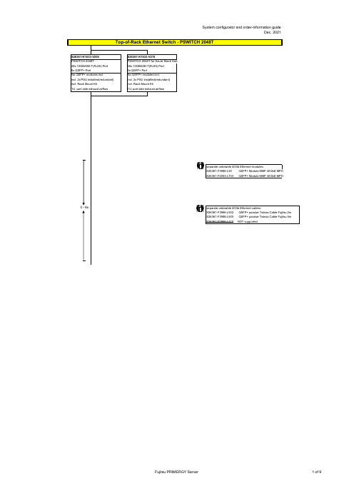
no power cord
T26139-Y3850-E10
T26139-Y1968-L180 T26139-Y1968-L250 T26139-Y1968-L10
T26139-Y1741-L90
T26139-Y1757-L10 T26139-Y1753-L10 T26139-Y1740-L10 T26139-Y1744-L10 T26139-Y1745-L10 T26139-Y1746-L10 T26139-Y1747-L18 T26139-Y1748-L10
Region Kits, 1x per System Region Kit Europe, Contains warranty sheet and safety instructions in German, English, French, Spanish, Italian, Polish, Russian and Welsh language
S26361-F1452-E100 S26361-F1452-E130
End of PSWITCH 2048T
CAT 6A S/STP RJ45 cables can be used for proper cabling: S26361-F3417-L602: CAT 6A, RJ45 connector, 2m S26361-F3417-L603: CAT 6A, RJ45 connector, 3m S26361-F3417-L605: CAT 6A, RJ45 connector, 5m S26361-F3417-L610: CAT 6A, RJ45 connector, 10m S26361-F3417-L615: CAT 6A, RJ45 connector, 15m
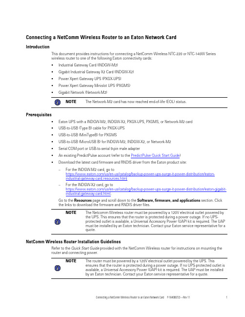
NetComm Wireless NTC-220或NTC-140W系列无线路由器与Eaton网络卡P
C o n n e c t i n g a N e t C o m m W i r e l e s s R o u t e r t o a n E a t o n N e t w o r k C a r dI n t r o d u c t i o nThis document provides instructions for connecting a NetComm Wireless NTC-220or NTC-140W Serieswireless router to one of the following Eaton connectivity cards:•Industrial Gateway Card(INDGW-M2)•Gigabit Industrial Gateway X2Card(INDGW-X2)•Power Xpert Gateway UPS(PXGX-UPS)•Power Xpert Gateway Minislot UPS(PXGMS)•Gigabit Network(Network-M2)NOTE The Network-M2card has now reached end-of-life(EOL)status.P r e r e q u i s i t e s•Eaton UPS with a INDGW-M2,INDGW-X2,PXGX-UPS,PXGMS,or Network-M2card•USB-to-USB(Type B)cable for PXGX-UPS•USB-to-USB(MiniTypeB)for PXGMS•USB-to-USB(MicroUSB B)for INDGW-M2,INDGW-X2,or Network-M2•Serial COM port or USB-to-serial9-pin male adapter•An existing PredictPulse account(refer to the PredictPulse Quick Start Guide)•Download the latest card firmware and RNDIS driver from the Eaton product site:–For the INDGW-M2card,go tohttps:///us/en-us/catalog/backup-power-ups-surge-it-power-distribution/eaton-industrial-gateway-card.resources.html–For the INDGW-X2card,go tohttps:///us/en-us/catalog/backup-power-ups-surge-it-power-distribution/eaton-gigabit-industrial-gateway-card.html.Go to the Resources page and scroll down to the Software,firmware,and applications section.Clickthe links to download the firmware and RNDIS driver files.NOTE The Netcomm Wireless router must be powered by a120V electrical outlet powered bythe UPS.This ensures that the router is protected during a power outage.If no UPS-protected outlet is available,a Universal Accessory Power(UAP)kit is required.The UAPmust be installed by an Eaton technician.Contact your Eaton service representative for aquote.N e t C o m m W i r e l e s s R o u t e r I n s t a l l a t i o n G u i d e l i n e sRefer to the Quick Start Guide provided with the NetComm Wireless router for instructions on mounting therouter and connecting power.NOTE The router must be powered by a120V electrical outlet powered by the UPS.Thisensures that the router is protected during a power outage.If no UPS-protected outlet isavailable,a Universal Accessory Power(UAP)kit is required.The UAP must be installedby an Eaton technician.Contact your Eaton service representative for a quote.I N D G W -M 2o r I N D G W -X 2C a r d I n s t a l l a t i o nThe hot-swappable INDGW-M2and INDGW-X2cards (see Figure 1and Figure 2)can be installed without turning off the UPS or disconnecting the load.To install the card:1.Ensure that the UPS has logic power.2.Remove the two screws securing the Minislot or X-slot cover and remove the cover from the UPS.Retain the screws.3.Remove the INDGW-M2or INDGW-X2card from its shipping package.4.Slide the card into the open slot.Secure with the screws removed in Step 2.5.Wait for the Warning LED (see Figure 1or Figure 2)to flash only green to indicate that the card is operational.The ON LED also flashes green when the card is ready.6.Connect a USB cable from the SETTINGS port of the INDGW-M2or INDGW-X2card to a USB port on the laptop.•Windows will automatically detect the INDGW-M2or INDGW-X2card connection 7.Open a web browser and enter https://169.254.0.1.You are prompted to log in.Figure 1.INDGW-M2CardFigure 2.INDGW-X2Card8.Log in using the username admin and password admin .9.You are prompted to change your password.Network Connector Network Speed LED Network Link/Activity LED AUX (EMP)ConnectorRESTART ButtonON LED Warning LEDSETTINGS/UPS Data Connector Modbus Connector INDGW-M2or INDGW-X2Card InstallationINDGW-M2or INDGW-X2Card Installation.10.Enter the new password Eaton123!,re-enter the new password,and press Submit11.Read and accept the license agreement.12.The INDGW-M2or INDGW-X2card home page displays(see Figure3).13.The green ON LED should be flashing to indicate that the card is operating normally(see Figure1orFigure2).wait10seconds,plug it back in,and wait3minutes.If the LED still does not flash,contact the Brightlayer DataCenter at800-356-5737,option2,option2to troubleshoot.Figure3.INDGW-M2or INDGW-X2Home Page ArrayI N D G W-M2o r I N D G W-X2C a r d F i r m w a r e U p d a t e1.As noted in the Prerequisites section,the installation requires the latest card firmware.To view thefirmware installed on the INDGW-M2or INDGW-X2card,click the Maintenance(wrench)icon on the cardhome page(see Figure3).The Firmware tab shown in Figure4displays.2.The Version column shows the firmware version of the card.To check the latest firmware for the networkcard:•For an INDGW-M2card,go tohttps:///us/en-us/catalog/backup-power-ups-surge-it-power-distribution/eaton-industrial-gateway-card.html•For an INDGW-X2card,go tohttps:///us/en-us/catalog/backup-power-ups-surge-it-power-distribution/eaton-gigabit-industrial-gateway-card.html3.Click Resources ,then scroll down and expand the Software,firmware,and applications section.Figure4.INDGW-M2or INDGW-X2Card Firmware Tab4.Note the latest available firmware version.If that version is later than the one on the network card,update the card firmware:a.Click the link to download and save that file to a known location.b.Remain connected to the card via the USB cable using the redirected IP address http://169.254.0.1.c.Select Maintenance from the left-hand menu and select Firmware at the top to display the UPDATE FIRMWARE page (see Figure 4).d.Click Upload to load the latest firmware to the card.Click Choose File to navigate to the firmware file saved in Step 4.b.e.Select the firmware file and click Upload .f.When the firmware update is completed,a prompt is displayed.Allow the card to reboot and wait 2–4minutes for completion.g.Log in to the card,return to the Firmware tab,and confirm that the firmware updated was successful.E n v i r o n m e n t a l M o n i t o r i n g P r o b e (E M P )G e n 2I n s t a l l a t i o n1.Remove the EMP and cable from the packaging.2.Install the EMP as directed in theEnvironmental Monitoring Probe Gen2EMPDT1H1C2Installation Instructions .•Set the MODBUS ADDRESS switches on each EMP as appropriate for your application (see Figure 5).For example,for an application with one EMP,set the switches as shown in Figure 5,with switch 1and TER (termination)in the 1position.For a multiple-EMP application,at least one switch must be set on each EMP in in the daisy-chain and the TER switch set on the last EMP in thedaisy-chain.INDGW-M2or INDGW-X2Card InstallationFigure 5.EMP MODBUS ADDRESSSwitches3.Connect the USB end of the cable to the AUX port on the INDGW-M2or INDGW-X2card and the RJ45end to the FROM DEVICE port on the EMP.If possible,route the cable into the battery cabinet and place the EMP in the battery cabinet.4.On the INDGW-M2or INDGW-X2home page (see Figure 3),select Environment from the left-hand menu to display the SENSOR COMMISSIONING page (see Figure 6).Figure 6.Sensor Commissioning Page5.As shown in Figure 6,no sensors have yet been discovered in the system.Click Discover to identify the EMP sensor(s).When discovered,the EMP is displayed as shown in Figure 7.•If no device is found,verify the EMP connections and settings and click Discoveragain.INDGW-M2or INDGW-X2Card InstallationFigure 7.EMP Sensor DiscoveredC o n n e c t i n g t h e R o u t e r t o a n I ND G W -M 2o r I N D G W -X 2C a r dTo connect the NTC-220or NTC-140W Series router to an INDGW-M2or INDGW-X2card:•Connect the Ethernet cable from the LAN port on the router to the Network connector on the INDGW-M2or INDGW-X2card (see Figure 1or Figure 2).•If the INDGW-M2or INDGW-X2card is located inside the UPS chassis,route the cable out of the chassis via a conduit hole that is protected by a rubber grommetOnce connected,the LEDs on the INDGW-M2or INDGW-X2card’s Network port should light and the green LED at the top left of the SETTINGS port should blink.C o n f i g u r i n g a n I ND G W -M 2o r I N D G W -X 2C a r dTo troubleshoot or set up the INDGW-M2or INDGW-X2card,refer to the INDGW-M2User’s Guide or INDGW-X2User’s Guide .The INDGW-M2or INDGW-X2card’s default configuration includes a DHCP network configuration.To configure the INDGW-M2or INDGW-X2card,connect to the card’s SETTINGS port with USB-to-USB (MicroUSB B)cable.Once connected,open an internet browser and navigate to 169.254.0.1to display the Network M2home page (see Figure 3).Log in using the default credentials:Username:adminPassword:adminYou are prompted to change your password.Enter a new password of at least eight characters,including one lowercase letter,one uppercase letter,one numeric character,and one special character.Record the new password.The INDGW-M2or INDGW-X2card will reboot and ask for the new password.Enter the web GUI and click Settings on the left sidebar menu.Click the Network &Protocol tab (see Figure 8).Verify the IPv4Mode is set to DHCP and record the IP address to be used later when configuring the PredictPulseWizard.INDGW-M2or INDGW-X2Card InstallationFigure 8.INDGW-M2or INDGW-X2Card Network &Protocol TabClick the General tab (see Figure 9).In the SMTP SETTINGS section:•Enter in the Server IP/Hostname field •To ensure that e-mails are not marked as spam,enter *************************in the Default sender address fieldScroll down and click Save in the bottom right.Figure 9.INDGW-M2or INDGW-X2Card General TabIn the SYSTEM DETAILS section,select the appropriate time zone and select the Dynamic (NTP)radio button.Enter 192.168.1.1in the NTP server field.For instructions on configuring NTP in the modem,see the Configuring a PXGX-UPS or PXGMS Card section.Also enter the Location ,Contact ,and System Name .Click Save .Proceed to the Run the PredictPulse Wizardsection.INDGW-M2or INDGW-X2Card InstallationP X G X-U P S o r P X G M S I n s t a l l a t i o nC o n n e c t i n g t h e R o u t e r t o a P X G X-U P S o r P X G M S C a r dConnect the NTC-220or NTC-140W Series router and Eaton network e the included Ethernet cable orequivalent.•For a PXGX-UPS card,connect the Ethernet cable from the LAN port on the router to the Upstream port on the card(see Figure10):•For a PXGMS card,connect the Ethernet cable from the LAN part on the router to the Ethernet10/100 port on the card(see Figure11)Route the Ethernet cable into the UPS via the appropriate conduit holes.Once connected,the LEDs on theactive Ethernet port,as well as the green Power LED and Status LEDs should light.Figure10.Power Xpert Gateway UPS(PXGX-UPS)CardFigure11.Power Xpert Gateway Minislot UPS(PXGMS)CardC o n f i g u r i n g a P X G X-U P S o r P X G M S C a r dTo troubleshoot or set up the PXGX-UPS or PXGMS card,refer to Sections3–5of thePXGX-UPS Quick Start Instructions or PXGMS Quick Start Instructions for instructions on connecting aWindows-based computer to the card’s Setup port using a USB cable.To configure the PXGX-UPS or PXGMS card,connect to the card’s Setup port using a USB cable.Onceconnected,open an internet browser and navigate to169.254.0.101.Log in using the default credentials:Username:adminPassword:adminNOTE The PXGX-UPS password may be the MAC address of the card.The PXGMS passwordmay be the card serial number.If installing on an existing PXGX-UPS or PXGMS card,reset the card to factory default settings as follows:•Locate the onboard DIP switch and set switch6to ONPXGX-UPS or PXGMS InstallationPXGX-UPS or PXGMS Installation•Reboot the card to restore the factory defaults•Return switch6to OFF and reboot the cardFor more information on restoring the factory default settings,refer to the PXGX-UPS Card User’s Guide or PXGMS Card User’s Guide.For a new installation,the PXGX-UPS or PXGMS card will use the factory default settings.From the Configuration menu(see Figure12),select E-mail to display the E-mail tab(see Figure13).MenuFigure12.Configuration ArrayEnsure that the SMTP server/IP hostname is and the recipient checkboxes are setup as shown in Figure13,with********************.com as the only e-mail recipient.TabFigure13.E-mailPXGX-UPS or PXGMS InstallationFigure14.E-Mail Event Trigger ConfigurationPageFigure15).Select the Synchronize with NTP server(s)radio button and enter192.168.1.1for the NTP serverIP address.Ensure that the correct time zone is selected for the Time zone for logs,e-mail,and connecteddevice.Click Apply after making any changes.TabFigure15.Date/Timethe network key printed on the back of the modem.Once connected,open an internet browser:•For an NTC-140W router,navigate to192.168.1.1•For an NTC-220router,navigate to https://192.168.1.1Log in using the default credentials(see Figure16):Username:adminPassword:adminFigure Comm Wireless Log-InPageNavigate to the Services tab and select Network Time (NTP).Ensure the correct time zone is selected and the remaining settings are as shown in Figure 17,with 151.110.127.39listed for NTP service.Click Save if any changes were made.Figure Comm Wireless ServicesTabProceed to the Run the PredictPulse Wizard section.PXGX-UPS or PXGMS InstallationN e t w o r k -M 2C a r d I n s t a l l a t i o nFor instructions on installing a Network-M2card,refer to the documentPredict Pulse ™Setup for an Eaton®Gigabit Network (Network-M2)Card .C o n n e c t i n g t h e R o u t e r t o a N e t w o r k -M 2C a r dTo connect the NTC-220or NTC-140W Series router to a Network-M2card:•Connect the Ethernet cable from the LAN port on the router to the Ethernet port on the Network-M2card (see Figure 18).•If the Network-M2card is located inside the UPS chassis,route the cable out of the chassis via a conduit hole that is protected by a rubber grommetOnce connected,the LEDs on the Network-M2card’s Ethernet port should light and the green LED at the top left of the SETTINGS port should blink.Figure work-M2CardC o n f i g u r i n g a N e t w o r k -M 2C a r dTo troubleshoot or set up the Network-M2card,refer to the Network-M2User’s Guide .The Network-M2default configuration includes a DHCP network configuration.To configure the Network-M2card,connect to the card’s SETTINGS port with USB-to-USB (MicroUSB B)cable.Once connected,open an internet browser and navigate to 169.254.0.1to display the Network M2home page (see Figure 19).Log in using the default credentials:Username:adminPassword:adminYou are prompted to change your password.Enter the new password Eaton123!,re-enter the new password,and press Submit.Entering a password other than Eaton123!will cause the PredictPulse activation to fail.Network-M2Card InstallationFigure work-M2Card Home PageThe Network-M2card will reboot and ask for the new password.Enter the web GUI and click Settings on the left sidebar menu.Click the Network &Protocol tab (see Figure 20).Verify the IPv4Mode is set to DHCP and record the IP address to be used later when configuring the PredictPulse Wizard.Figure work-M2Card Network &Protocol TabClick the General tab (see Figure 21).In the SMTP SETTINGS section:•Enter in the Server IP/Hostname field •To ensure that e-mails are not marked as spam,enter *************************in the Default sender addressfieldNetwork-M2Card InstallationFigure work-M2Card General TabScroll down and click Save in the bottom right.In the SYSTEM DETAILS section,select the appropriate time zone and select the Dynamic (NTP)radio button.Enter 192.168.1.1in the NTP server field.For instructions on configuring NTP in the modem,see the Configuring a PXGX-UPS or PXGMS Card section.Also enter the Location ,Contact ,and System Name .Click Save .Proceed to the Run the PredictPulse Wizard section.C o n n e c t i n g a P o w e r X p e r t E t h e r n e t S w i t c hSome installations have multiple UPSs with network cards that must be connected.In these cases,install a four-or six-port Power Xpert Ethernet Switch (see Figure 22).Install an Eaton Power Xpert Ethernet Switch to the DIN rail and apply power.Connect a straight-through Ethernet CAT5cable between the WAN port on the wireless router and port 1on the Power Xpert Ethernet Switch.Connect another straight-through Ethernet cable from the Upstream port on the PXGX-UPS or Ethernet port on the PXGMS or Network-M2to any open port other than 1on the Power Xpert EthernetSwitch.Connecting a Power Xpert Ethernet SwitchFigure 22.Power Xpert EthernetSwitchesR u n t h e P r e d i c t P u l s e W i z a r dTo run the PredictPulse Wizard (ActivatePredictPulse.exe ),connect a laptop or personal computer as follows.For a PXGX-UPS card,using an RJ-45Ethernet cable,connect the laptop or personal computer to the card’s Downstream port.For a PXGMS ,Network-M2,INDGW-M2or INDGW-X2card,using an RJ-45Ethernet cable,connect the laptop or personal computer to the LAN/WAN port on the router.You can also run the PredictPulse wizard while connected to the modem Wi-Fi.For instructions on connecting to the modem Wi-Fi,see the Configuring an INDGW-M2or INDGW-X2Card ,Configuring a PXGX-UPS or PXGMS Card ,or Configuring a Network-M2Card section.Run the PredictPulse Wizard (ActivatePredictPulse.exe ).The Eaton PredictPulse window displays (see Figure 23).Figure 23.PredictPulse Wizard InitialDisplayEnter the Organization Code and customer E-Mail Address and click Begin Registration .The PredictPulse Device Activation window displays (see Figure 24).Run the PredictPulse WizardFigure 24.PredictPulse Device ActivationWindowEnter the IP address or a range of IP addresses to continue.The wizard attempts to connect to a UPS at thataddress.NOTE For a PXGX-UPS or PXGMS card,the IP address assigned by the modem can be foundon the Configuration menu.Select Network ,verify that DHCP Enabled is checked(see Figure 25),and the IP address is listed.If DHCP was not enabled initially,you mayneed to reboot the card to have the modem assign an IP address.Figure 25.DHCPEnabledThe IP address can also be found from the modem GUI.Navigate to the Networking tab,select LAN on the sidebar and DHCP under the drop-down menu (see Figure 26).Scroll down to the Dynamic DHCP client list (see Figure 27)to find the connected devices.The web card IP will have an asterisk as the Computer name.Run the PredictPulse WizardFigure Comm Wireless DHCPTabFigure 27.Dynamic DHCP ClientListNOTE If the wizard displays the configuration error message shown in Figure 28,enter thecard’s username and password and click OK .Figure 28.PredictPulse Wizard Card ConfigurationErrorThe PredictPulse wizard activates each card.Upon completion,the wizard displays a confirmation message (see Figure 29).Run the PredictPulse WizardNOTE If the user is running Microsoft Outlook and it is open,an activation e-mail is sentautomatically to Eaton’s PredictPulse servers.You may need to send the e-mail fromyour Drafts or Outbox folder once you've connected to a LAN if you were connected tothe modem Wi-Fi while running the wizard.If the user does not have Outlook installed,the e-mail components are saved in the user’s My Documents folder and instructionsare provided for sending the activation e-mail manually.Figure29.Activation CompleteWindowNOTE The registration process to activate the unit for PredictPulse may take15minutes ormore.To ensure the PredictPulse activation was successful,call the Brightlayer DataCenter at800-356-5737,option2,option2for assistance.P r e d i c t P u l s e R e m o t e M o n i t o r i n g A c t i v a t i o n C o m p l e t i o n C h e c k l i s t•https:// account enrollment complete•Universal Accessory Power kit installed(if no UPS protected outlet is available for the modem and/or network switch to plug into.Must be installed by an Eaton technician,contact your Eaton servicerepresentative for a quote.)•Network switch installed(if multiple UPS are connected to the same modem)•PredictPulse-compatible network connectivity card installed•Connectivity card upgraded to latest firmware•Connectivity card configured for PredictPulse•Modem NTP configured•Environmental Monitoring Probe connected•PredictPulse activation wizard run from modem connection•Call placed to the Brightlayer Data Center at800-356-5737,option2,option2to confirm portal activation and communication receiptPredictPulse Remote Monitoring Activation Completion ChecklistT r o u b l e s h o o t i n gS i g n a l S t r e n g t hThe biggest risk for the router is low signal quality.As an initial test,observe AT&T cell phone signal strength in the area of installation.To quantify the signal,connect an Ethernet cable to the router.Once connected,open an internet browser and navigate to 192.168.1.1.Log into the router’s Status page (see Figure 30)using the credentials:Username:adminPassword:adminOn the Status page,observe the Signal strength (dBm)and position the router to maximize the value.If the signal is weak,an external antenna may be required.The external antenna replaces the 3G antennas provided with the router.Once connected,position the external antenna to maximize the signal strength.Figure Comm Wireless StatusPageTroubleshootingI n c o r r e c t P r o f i l eThe wireless router can only use the profile stored on the SIM.On the router’s Networking page (see Figure 31),verify that Profile1is selected and that the APN is .attz ,as shown.Figure Comm Wireless NetworkingPageR e b o o t i n g t h e R o u t e rIf the wireless router loses connection to the connectivity card,the router can be rebooted from the router's System page (see Figure 32).The connection will be interrupted momentarily while the SIM data loads.Figure Comm Wireless SystemPageR e m o t e R e b o o t F u n c t i o nAlthough not required,Eaton recommends enabling the remote reboot function of your router to assist Eaton specialists in remotely troubleshooting.To do so,navigate to the router’s Services page (see Figure 33).Remote Reboot FunctionConnecting a NetComm Wireless Router to an Eaton Network Card P-164000722—Rev 1121Figure Comm Wireless ServicesPageScroll down and click SMS Messaging .From the SMS Messaging drop-down menu,select Diagnostics (see Figure 34).Figure Comm Wireless SMS Messaging Drop-DownMenuRemote Reboot Function22Connecting a NetComm Wireless Router to an Eaton Network Card P-164000722—Rev 11Ensure that the selections are set as shown in Figure 35,with:•Enable remote diagnostics and command execution –ON •Only accept authenticated SMS messages –OFF •Send Set command acknowledgement replies –OFF •Access advanced RDB variables –OFF •Allow execution of advanced commands –ON •Send acknowledgement replies –the sender’s number •Send command error replies –OFF •Send error replies to –the sender’s number •Send a maximum number of –100–replies per –day •White list –should be emptyClick Save .Figure Comm Wireless SMS DiagnosticsSettingsA d d i t i o n a l I n f o r m a t i o n a n d S u p p o r tFor additional information about PredictPulse,visit /PredictPulse .For specific questions,call the Brightlayer Data Center at 800-356-5737,option 2,option 2.Additional Information and SupportAdditional Information and Support Connecting a NetComm Wireless Router to an Eaton Network Card P-164000722—Rev1123P-16400072211P-16400072211。
超强K620系列信创服务器 用户指南说明书
机架式服务器产品说明书——超强K620系列信创服务器用户指南前言前言概述本文档介绍了超强K620鲲鹏服务器的产品外观,结构,组件和规格,指导用户对超强K620进行安装、连线、上电下电、基本配置、安装操作系统及处理故障等操作。
本文档适用于鲲鹏920处理器以下型号:7260、5250、5230、7265、5255、5220和3210。
其中,7260原为6426、5250对原为4826、5230原为3226。
符号约定在本文中可能出现下列标志,它们所代表的含义如下。
目录前言...................................................................................................................................................... i i 1简介 .. (1)1.1 物理结构 (1)1.2 逻辑结构 (3)2组件 (7)2.1 前面板组件 (7)2.2 前面板指示灯和按钮 (10)2.3 后面板组件 (13)2.4 后面板指示灯 (15)2.5 灵活IO 卡 (16)2.6 硬盘编号及指示灯 (17)2.6.1 硬盘编号 (17)2.6.2 SAS/SATA 硬盘指示灯 (21)2.6.3 NVMe 硬盘指示灯 (21)2.7 Riser 卡和PCIe 插槽 (22)2.8 风扇 (28)3产品规格 (30)3.1 技术规格 (30)3.2 环境规格 (33)3.3 物理规格 (35)3.4 电源规格 (35)4软硬件兼容性 (36)5安装与配置 (37)5.1 工具准备 (37)5.2 设备上的标志 (38)5.3 防静电 (39)5.3.1 操作准则 (39)5.3.2 佩戴防静电腕带 (40)5.4 安装环境要求 (40)5.4.1 空间要求与通风要求 (40)5.4.2 温度要求与湿度要求 (41)5.4.3 机柜要求 (41)5.5 拆除机箱外包装 (41)5.6 安装硬件选件 (42)5.7 安装导轨及服务器 (42)5.7.1 安装L 型滑道及服务器 (42)5.7.2 安装可伸缩滑道及服务器 (45)5.8 连接外部线缆 (46)5.8.1 布线指导 (46)5.8.2 连接鼠标、键盘和VGA 接口线缆 (47)5.8.3 连接网线 (48)5.8.4 连接光口线缆 (49)5.8.5 连接USB 设备 (52)5.8.6 连接串口线缆 (53)5.8.7 连接电源线缆 (54)5.8.7.1 连接交流电源线缆 (54)5.8.7.2 连接直流电源线缆 (55)5.8.8 检查线缆连接 (56)5.9 上电与下电 (57)5.10 初始配置 (59)5.10.1 默认数据 (59)5.10.2 配置简介 (60)5.10.3 查询管理网口IP 地址 (61)5.10.4 登录iBMC Web 界面 (64)5.10.5 检查服务器 (65)5.10.6 修改初始密码 (69)5.10.7 配置RAID. (73)5.10.8 设置BIOS. (73)5.10.9 安装操作系统 (81)5.10.10 使系统保持最新状态 (81)6故障处理指导 (83)7维保与安全 (84)7.1 维保与保修 (84)7.2 安全 (84)8常用操作 (85)8.1 登录远程虚拟控制台 (85)8.1.1 通过iBMC WEB 登录服务器远程虚拟控制台 (85)8.1.2 使用独立远程控制台登录服务器实时桌面 (90)8.2 登录iBMC 命令行 (95)8.3 使用PuTTY 登录服务器(串口方式) (98)8.4 使用PuTTY 登录服务器(网口方式) (100)8.5 查询服务器处理器型号 (102)9更多资源 (106)9.1 技术支持 (106)9.2 维护工具 (107)A 附录 (108)A.1 BIOS. (108)A.2 iBMC (109)A.3 术语 (109)A.4 缩略语 (111)A.5 传感器列表(配置鲲鹏920 7260、5250、5230、7265 或5255 处理器) (114)A.6 传感器列表(配置鲲鹏920 5220 或3210 处理器) (117)1 简介超强K620鲲鹏服务器是基于鲲鹏920处理器的数据中心服务器,K620是2U 2路机架服务器。
莫克A V2201系列极小型x86嵌入式计算机产品说明书

P/N: 1802022010015 *1802022010015*V2201 SeriesQuick Installation GuideVersion 3.3, April 2023Technical Support Contact Information/support2023 Moxa Inc. All rights reserved.OverviewThe Moxa V2201 Series ultra-compact x86 embedded computer is based on the Intel® Atom™ E3800 Series processor, features the most reliable I/O design to maximize connectivity, and supports dual wireless modules, making it suitable for a diverse range of communication applications. The computer’s thermal design ensures reliable system operation in temperatures ranging from -40 to 85°C, and wireless operation in temperatures ranging from -40 to 70°C with a special purpose Moxa wireless module installed. The V2201 Series supports Proactive Monitoring function for device I/O status monitoring and alerts, system temperature monitoring and alerts, and system power management. Closely monitoring the system status makes it easier to recover from errors and provides the most reliable platform for your applications.Package ChecklistBefore installing the V2201, verify that the package contains the following items:•V2201 embedded computer•Terminal block to power jack converter•Wall mounting kit•Quick installation guide (printed)•Warranty cardNOTE Notify your sales representative if any of the above items are missing or damaged.V2201 Panel LayoutThe following figures show the panel layouts of the V2201-W models. In the “non -W” models, the five antenna connectors will not be installed during production.Front PanelRight PanelLeft PanelLED IndicatorsThe following table describes the LED indicators located on the front panel of the V2201.LED Name Status Function Power Green Power is on and computer is functioning normally.Off Power is offUser Defined Red Event has occurred Off No alert mSATA Yellow Blinking: Data is being transmittedOff Not connected / No data transmissionSD Card Yellow Blinking: Data is being transmittedOff Not connected / No data transmissionWireless 1 Green Steady On: Link is OnBlinking: Data is being transmittedOff Not connectedWireless 2 Green Steady On: Link is OnBlinking: Data is being transmittedOff Not connectedLAN 1 Yellow Steady On: 1000 Mbps Ethernet linkBlinking: Data is being transmittedGreen Steady On: 100 Mbps Ethernet linkBlinking: Data is being transmittedLED Name Status FunctionOff 10 Mbps Ethernet link or LAN is not connectedLAN 2 Yellow Steady On: 1000 Mbps Ethernet linkBlinking: Data is being transmittedGreen Steady On: 100 Mbps Ethernet linkBlinking: Data is being transmittedOff10 Mbps Ethernet link or LAN is not connectedTx 1 Green Blinking: Data is being transmittedOff Not connectedTx 2 Green Blinking: Data is being transmittedOff Not connectedRx 1 Yellow Blinking: Data is being transmittedOff Not connectedRx 2 Yellow Blinking: Data is being transmittedOff Not connectedNOTE The Mini PCIe card’s LED behavior depends on the moduleInstalling the Wireless ModulesThe V2201 has two Mini PCIe sockets on the rear panel. One socket only supports USB signals using the MC9090, MC7354, or MC7354 Mini PCIe cards. The other socket supports standard USB and PCIe signals.STEP1: Loosen the four screws located at the middle of the rear panel and open the cover.STEP 2: Insert the wireless module card at an angle.STEP 3: Push the wireless module card down and fasten it with the two screws included with the product.The V2201 has the following two Mini PCIe sockets.Socket 1: USB signal, for 3G/LTE Mini PCIe card (Sierra Wireless MC9090, MC7304, or MC7354). NOTE: The cellular card heat sink is installed in socket 1. Socket 2: Standard USB + PCIe signals, for Wi-Fi Mini PCIe card (SparkLAN WPEA-252NI).STEP 4: Connect the corresponding wireless module cards to connectors of the Mini PCIe sockets.The following five connectors are available:No. 1 & No. 3:For the Wi-Fi Mini PCIe card No. 2 & No. 4:For the 3G/LTE Mini PCIe card No. 5:For the GPS moduleSTEP 5: Replace the rear cover.You can also purchase and install external antennas from Moxa. Contact a Moxa sales representative for information.After installing the wireless modules and wireless external antennas, the computer should appear as follows:Installing the V2201DIN-rail MountingThe DK-DC50131 die-cast metal kit (shipped only with V2201-E4-W-T-LX; to be purchased separately for all other models), enables easy and robust installation of the V2201. Use the six M4*6L FMS screwsincluded to attach the DIN-rail mounting kit to the side panel of theV2201.Installation:STEP 1:Insert the upper lip of the DIN rail intothe DIN-rail mounting kit.STEP 2:Press the V2201 towards the DIN railuntil it snaps into place.Removal:STEP 1:Pull down the latch on themounting kit with a screwdriver.STEP 2 & 3:Use the screwdriver to pry theV2201 slightly forward away fromthe DIN rail, and then lift theV2201 upwards to remove it fromthe DIN rail.STEP 4:Press the recessed button on the spring-loaded bracket to lock it into position untilthe next time you need to install theV2201 on to a DIN rail.Wall or Cabinet MountingThe V2201 computers (with the exclusion of the V2201-E4-W-T-LX model) come with two metal brackets for attaching to a wall or the inside of a cabinet. Four screws (Phillips truss headed, M3*6L, and nickel plated with Nylok®) are included in the kit.Step 1:Use two screws for eachbracket and attach the bracketto the rear of the V2201.Step 2:Use two screws on each side toattach the V2201 to a wall orcabinet.The product package does notinclude the four screws requiredfor attaching the wall-mountingkit to the wall or cabinet; theyneed to be purchasedseparately. We recommendusing standard M3*5L screws.Connector DescriptionPower ConnectorConnect the 9 to 36 VDC LPS or Class 2 power line to the V2201’s terminal block. If the power is supplied properly, the Power LED will light up. The OS is ready when the Ready LED glows a solid green.Grounding the V2201Grounding and wire routing help limit the effects of noise due to electromagnetic interference (EMI). Run the ground connection from the grounding screw (M4) to the grounding surface prior to connecting the power.SG:The Shielded Ground (sometimes calledProtected Ground) contact is the right most oneon the 3-pin power terminal block connector when viewed from the angle shown here.Connect the SG wire to an appropriate grounded metal surface.HDMI OutputsThe V2201 comes with a type A HDMI female connector on the front panel to connect an HDMI monitor.The screw hole above the HDMI connector is used to attach a custom lock to the HDMI connector; a custom lock is needed since the shape of different HDMI connectors are not the same. Please contact a Moxa sales representative for details. Before Attaching the LockAfter Attaching the LockEthernet PortsThe 10/100/1000 Mbps Ethernet ports use RJ45 connectors.Pin 10/100 Mbps 1000 Mbps1 ETx+ TRD(0)+2 ETx- TRD(0)-3 ERx+ TRD(1)+4 – TRD(2)+5 – TRD(2)-6 ERx- TRD(1)-7 – TRD(3)+8 – TRD(3)-Serial PortsThe serial ports use DB9 connectors. Each port can be configured by software for RS-232, RS-422, or RS-485. The pin assignments for the ports are shown in the following table:Pin RS-232 RS-422 RS-485(4-wire)RS-485(2-wire)1 DCD TxDA(-) TxDA(-) –2 RxD TxDB(+) TxDB(+) –3 TxD RxDB(+) RxDB(+) DataB(+)4 DTR RxDA(-) RxDA(-) DataA(-)5 GND GND GND GND6 DSR – – –7 RTS – – –8 CTS – – –SD SlotThe V2201 has an SD slot for storage expansion. The SD slot allows users to plug in an SD 3.0 standard SD card. To install an SD card, gently remove the outer cover from the left, and then insert the SD card into the slot.Mini SIM SlotThe V2201 has a Mini SIM slot for 3G/LTE wireless Internet connections. To install a Mini SIM card, gently remove the outer cover from the left, and insert the card into the slot.USB HostsThe V2201 has 1 USB 3.0 and 2 USB 2.0 Type-A connectors. 2 USB 2.0 ports are located on the front panel, and 1 USB 3.0 port is on the right panel. The port supports keyboard and mouse and can also be used to connect a Flash drive for storing additional data.Audio InterfaceThe audio output of the V2201 is combined with the HDMI connector.DI/DOThe V2201 comes with four digital inputs and four digital outputs on a 2 x 5 terminal block.Reset ButtonPress the “Reset Button” on the left side panel of the V2201 to reboot the system automatically. Real-time ClockThe V2201’s real-time clock is powered by a lithium battery. Westrongly recommend that you do not replace the lithium battery without help from a qualified Moxa support engineer. If you need to change the battery, contact the Moxa RMA service team.Powering on the V2201To power on the V2201, connect the “terminal block to power jack converter” to the V2201’s DC terminal block (located on the sidepanel), and then connect the 9 to 36 VDC power adapter. The computer is automatically switched on once the power adapter is plugged in. If it does not, press the Power Button to turn on the computer. Note that the Shielded Ground wire should be connected to the top pin of the terminal block. It takes about 30 seconds for the system to boot up. Once the system is ready, the Power LED will light up.Connecting the V2201 to a PCPower on the V2201 computer after connecting a monitor, keyboard, and mouse, and verifying that the power source is ready. Once the operating system boots up, the first step is to configure the Ethernet interface. The factory default settings for the V2201’s LANs are shown below (W7E uses DHCP):Default IP AddressNetmaskLAN 1 192.168.3.127 255.255.255.0 LAN 2 192.168.4.127255.255.255.0- 11 - Configuring the Ethernet Interface Linux OSIf you use the console cable to configure network settings for the first time, use the following commands to edit the interfaces file:#ifdown –a //Disable LAN1~LAN2 interface first, before you reconfigure the LAN settings. LAN1 = eth0, LAN2 = eth1// #vi /etc/network/interfaces //check the LAN interface first//After the boot setting of the LAN interface has been modified, use the following commands to immediately activate the LAN settings: #sync; ifup –a W7E OSSTEP 1: Go to Start → Control Panel → Network and Internet → Viewnetwork status and tasks → Change adapter setting.STEP 2: In the Local Area Connection Properties screen, click InternetProtocol (TCP/IP) and then select Properties. Select InternetProtocol Version 4, and then click Properties.STEP 3: Click OK after inputting the proper IP address and netmask.NOTERefer to the V2201 user’s manuals for additional configuration information.。
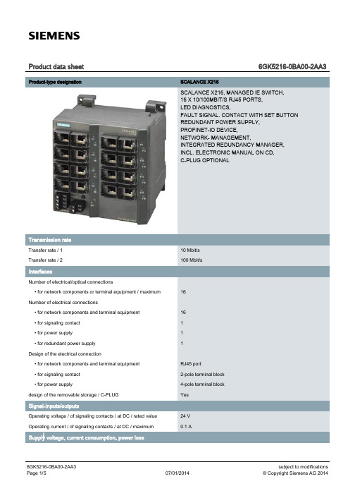
Siemens SCALANCE X216 16-Port Managed Industrial E
Product data sheet6GK5216-0BA00-2AA3 Product-type designation SCALANCE X216SCALANCE X216, MANAGED IE SWITCH,16 X 10/100MBIT/S RJ45 PORTS,LED DIAGNOSTICS,FAULT SIGNAL. CONTACT WITH SET BUTTONREDUNDANT POWER SUPPLY,PROFINET-IO DEVICE,NETWORK- MANAGEMENT,INTEGRATED REDUNDANCY MANAGER,INCL. ELECTRONIC MANUAL ON CD,C-PLUG OPTIONALTransfer rate / 110 Mbit/sTransfer rate / 2100 Mbit/sNumber of electrical/optical connections• for network components or terminal equipment / maximum16Number of electrical connections• for network components and terminal equipment16• for signaling contact1• for power supply1• for redundant power supply1Design of the electrical connection• for network components and terminal equipment RJ45 port• for signaling contact2-pole terminal block• for power supply4-pole terminal blockdesign of the removable storage / C-PLUG YesOperating voltage / of signaling contacts / at DC / rated value24 VOperating current / of signaling contacts / at DC / maximum0.1 AType of / supply voltage DCSupply voltage / external24 V• minimum18 V• maximum32 VProduct component / fusing at power supply input YesType of fusing / at input for supply voltage1,1 A / 33 VConsumed current / maximum0.24 AActive power loss / at 24 V / for DC 5.76 WAmbient temperature• during operating-40 … +60 °C• during storage-40 … +70 °C• during transport-40 … +70 °C95 %Relative humidity / at 25 °C / without condensation / during operating/ maximumProtection class IP IP30Design compactWidth120 mmHeight125 mmDepth124 mmNet weight 1.2 kgMounting type• 35 mm DIN rail mounting Yes• wall mounting Yes• S7-300 rail mounting YesCascading in the case of a redundant ring / at reconfiguration time of50<\~0.3\~sCascading in cases of star structuring Any (depending only on signal propagation time) Product function• CLI Yes• web-based management Yes• MIB support Yes• TRAPs via email Yes• Configuration with STEP 7Yes• Port mirroring Yes• for IRT / PROFINET IO switch No• PROFINET IO diagnosis Yes• switch-managed YesProtocol / is supported• Telnet Yes • HTTP Yes • HTTPS Yes • TFTP Yes • FTP Yes • BOOTP No • SNMP v1Yes • SNMP v2Yes • SNMP v3Yes • DCP Yes • LLDP Yes Identification & maintenance function• I&M0 - device-specific information Yes • I&M1 – higher level designation/location designation YesProduct function• Port diagnostics Yes • Statistics Packet Size Yes • Statistics packet type Yes • Error statistics YesProduct function / DHCP client YesProduct function• Ring redundancy Yes • Redundancy manager Yes • Standby redundancy No • High Speed Redundancy Protocol (HRP)Yes • Media Redundancy Protocol (MRP)Yes • Parallel Redundancy Protocol (PRP)No • Passive listening Yes Protocol / is supported / PRP YesProtocol / is supported / SSH YesProduct function / SICLOCK support Yes Protocol / is supported• NTP No• SNTP YesStandard• for EMC / from FM FM3611: Class 1, Division 2, Group A, B, C, D / T4, CL.1, Zone 2,GP. IIC, T4• for hazardous zone EN 60079-0 : 2006, EN 60079-15: 2005, II 3 G Ex nA II T4 KEMA 07ATEX 0145X• for safety / of CSA and UL UL 60950-1, CSA C22.2 No. 60950-1• for hazardous area / of CSA and UL ANSI / ISA 12.12.01, CSA C22.2 No. 213-M1987, CL. 1 / Div. 2 / GP.A, B, C, D T4, CL. 1 / Zone 2 / GP. IIC, T4• for emitted interference EN 61000-6-4:2001 (Class A)• for interference immunity EN 61000-6-2:2001Verification of suitability EN 61000-6-2:2001, EN 61000-6-4:2001• CE mark Yes• C-Tick Yes• KC approval Yes• Railway application in accordance with EN 50155No• Railway application in accordance with EN 50124-1NoMarine classification association• American Bureau of Shipping Europe Ltd. (ABS)Yes• Bureau Veritas (BV)Yes• Det Norske Veritas (DNV)Yes• Germanische Lloyd (GL)Yes• Lloyds Register of Shipping (LRS)Yes• Nippon Kaiji Kyokai (NK)Yes• Polski Rejestr Statkow (PRS)NoInternet-Link• to website: Industry Mall /industrial-controls/mall• to website: Industrial communication /simatic-net• to website: Information and Download Center /automation/net/catalog• to website: Image database /bilddb• to website: CAx Download Manager /cax• to website: Industry Online Support Security information Siemens provides products and solutions with industrial securityfunctions that support the secure operation of plants, solutions,machines, equipment and/or networks. They are importantcomponents in a holistic industrial security concept. With this inmind, Siemens’ products and solutions undergo continuousdevelopment. Siemens recommends strongly that you regularlycheck for product updates. For the secure operation of Siemensproducts and solutions, it is necessary to take suitable preventiveaction(e.g. cell protection concept) and integrate each componentinto a holistic, state-of-the-art industrial security concept. Third-partyproducts that may be in use should also be considered. For moreinformation about industrial security, visit/industrialsecurity. To stay informed aboutproduct updates as they occur, sign up for a product-specificnewsletter. For more information, visit. Version 3.4 – 14.11.2013-Siemens AG, I IA L CG, Nurembergletzte Änderung:Jun 16, 2014。
RT1710S USB Type-C Cable ID 商品说明书

RT1710SCopyright © 2017 Richtek Technology Corporation. All rights reserved. is a registered trademark of Richtek Technology Corporation.DS1710S-00 February 2017Cable ID for USB Type-C CablesGeneral DescriptionThe RT1710S is a Type-C cable ID for active and passive cables. All USB Full-Featured Type-C cables shall be electronically marked. Electronically marked cables shall support USB Power Delivery Structured VDM Discover Identity command directed to SOP’. This provides a method to determine the characteristics of the cable, e.g. its current carrying capability, its performance, vendor identification, etc. This may be referred to as the USB Type-C Cable ID function. The RT1710S is available in a WDFN-8L 2x2 package.Ordering InformationG : Green (Halogen Free and Pb Free)Note :Richtek products are :④ RoHScompliant and compatible with the current requirements of IPC/JEDEC J-STD-020.④ Suitablefor use in SnPb or Pb-free solderingprocesses.Marking Information42 : Product CodeW : Date CodeFeatures● Support SOP ’ Communication ● Integrated Transceiver (BMC PHY) ● Embedded Both Side RA Resistor ● Embedded Both Side ISO Diode ● Embedded MTP●Support Multi-Time Writable Memory to Store VDM Data●Support 4V to 5.5V Operation on VCON1/VCON2 Pin●Built-in Slew Rate Control for BMC Signal to Reduce the Effect of EMI●Support Custom Structured VDM Writing Through CC Pin● Support I 2C Bus for Programming VDM Data ●8-Lead WDFN PackageApplications●USB Full-Featured Type-C CablesPin Configuration(TOP VIEW)VCON1CCIN NC(DG0)NC(DG1)VCON2SDAGND SCL 76512348G N D9WDFN-8L 2x2RT1710STypical Application CircuitElectronically Marked Cable with VCONN connected through the cableElectronically Marked Cable with SOP’ at both endsRT1710SFunctional Block DiagramOperationSOP’ Communication is recognized by electronics in one Cable Plug (which may be attached to either the UFP or DFP). SOP Communication between the Port Partners is not recognized by the Cable Plug. the term Cable Plug in the SOP’ Communication case is used to represent a logical entity (RT1710S) in the cable which is capable of PD Communication. Both SOP Communication and SOP’ Communication take place over a single wire (CC pin). For a product which does not recognize SOP’ Packets, this will look like a non-idle channel.RT1710SCopyright © 2017 Richtek Technology Corporation. All rights reserved. is a registered trademark of Richtek Technology Corporation.Absolute Maximum Ratings (Note1)● VCON1/VCON2-------------------------------------------------------------------------------------------------------- -0.3V to 6V ●Power Dissipation, P D @ T A = 25︒CWDFN-8L 2x2 ---------------------------------------------------------------------------------------------------------- 2.19W ●Package Thermal Resistance (Note 2)WDFN-8L 2x2, θJA ---------------------------------------------------------------------------------------------------- 45.5°C/W WDFN-8L 2x2, θJC ---------------------------------------------------------------------------------------------------- 11.5°C/W ● Lead Temperature (Soldering, 10 sec.) -------------------------------------------------------------------------- 260︒C ● Junction Temperature ------------------------------------------------------------------------------------------------ 150︒C● Storage Temperature Range --------------------------------------------------------------------------------------- -65︒C to 150︒C ●ESD Susceptibility (Note 3)HBM (Human Body Model) ----------------------------------------------------------------------------------------- 8kV MM (Machine Model) ------------------------------------------------------------------------------------------------- 200VRecommended Operating Conditions (Note 4)● Supply Input Voltage ------------------------------------------------------------------------------------------------- 4V to 5.5V ● Ambient Temperature Range--------------------------------------------------------------------------------------- -40︒C to 85︒C ●Junction Temperature Range -------------------------------------------------------------------------------------- -40︒C to 125︒CElectrical Characteristics(V DD = 5V, T A = 25︒C, unless otherwise specified)RT1710SNote 1. Stresses beyond those listed “Absolute Maximum Ratings” may cause permanent damage to the device. These arestress ratings only, and functional operation of the device at these or any other conditions beyond those indicated in the operational sections of the specifications is not implied. Exposure to absolute maximum rating conditions may affect device reliability. Note 2. θJA is measured under natural convection (still air) at T A = 25°C with the component mounted on a higheffective-thermal-conductivity four-layer test board on a JEDEC 51-7 thermal measurement standard. θJC is measured at the exposed pad of the package. Note 3. Devices are ESD sensitive. Handling precaution recommended. Note 4. The device is not guaranteed to function outside its operating conditions.Data InBMC0 1 0 1 0 1 0 1 0 0 0 1 1 0 0 0 1 1PreambleSync-1Sync-1BMC ExampleInter-Frame Gap TimingsBMC Encoded Start of PreambleRT1710SFinal bit Preamble forTransmitting or Receiving BMC Encoded Frame TerminatedRT1710SY9Y8Y7Y6Y5Y4Y3Y2Y1BMC Tx ‘ONE’ MaskY9Y8Y7Y6Y5Y4Y3Y2Y1BMC Tx ‘ZERO’ MaskRT1710SApplication InformationStart of Packet Sequence Prime (SOP’)The SOP’ ordered set is defined as: two Sync-1 K-codes followed by two Sync-3 K-codesA Cable Plug capable of SOP’ Communications shall only detect and communicate with packets starting with SOP’.A DFP or Source needing to communicate with a Cable Plug capable of SOP’ Communications, attached between a Port Pair will be able to communicate using both packets starting with SOP’ to communicate with the Cable Plug and starting with SOP to communicate with its Port Partner. The DFP or Source shall co-ordinate SOP and SOP’ Communication so as to avoid collisions.Structured VDM Setting the VDM Type field to 1 (Structured VDM) defines the use of bits Bit[14:0] in the Structured VDM Header. The fields in the Structured VDM Header are defined in Table.The following rules apply to the use of Structured VDM messages:●Structured VDMs shall only be used when an Explicit Contract is in place with the following exception :Prior to establishing an Explicit Contract a Source may issue Discover Identity messages, to a Cable Plug using SOP’ Packets, as an Init iator.●Only the DFP shall be an Initiator of Structured VDMs except for the Attention Command that shall only be initiated by the UFP.●Only the UFP or a Cable Plug shall be a Responder to Structured VDMs.●Structured VDMs shall not be initiated or responded to under any other circumstances.● A DFP or UFP which does not support Structured VDMs shall ignore any Structured VDMs received. ● A Command sequence shall be interruptible e.g. due to the need for a message sequence using SOP Packets.RT1710SDiscover IdentityThe Discover Identity Command is provided to enable an Initiator (DFP) to identify its Port Partner and for an Initiator (Source or DFP) to identify the attached Cable Plug (Responder).The SVID in the Discover SVIDs Command shall be set to the PD SID by both the Initiator and the Responder for this Command.The Discover Identity Command sent back by the Responder contains an ID Header, a Cert Stat VDO and some Type specific VDOs which depend on the Product Type. This specification defines the following Type specific VDOs: ID HeaderThe ID Header contains the Vendor ID corresponding to the Power Delivery Product.RT1710SCert Stat VDOThe Cert Stat VDO contains the Test ID (TID) allocated by USB-IF during certification.Product VDOThe Product VDO contains identity information relating to the product.Cable VDOThe Cable VDO defined in this section shall be sent when the Product Type is given as Passive or Active Cable.Thermal ConsiderationsThe junction temperature should never exceed the absolute maximum junction temperature T J(MAX), listed under Absolute Maximum Ratings, to avoid permanent damage to the device. The maximum allowable power dissipation depends on the thermal resistance of the IC package, the PCB layout, the rate of surrounding airflow, and the difference between the junction and ambient temperatures. The maximum power dissipation can be calculated using the following formula :P D(MAX) = (T J(MAX) - T A ) / θJAwhere T J(MAX) is the maximum junction temperature, T A is the ambient temperature, and θJA is the junction-to-ambient thermal resistance.For continuous operation, the maximum operating junction temperature indicated under Recommended Operating Conditions is 125°C. The junction-to-ambient thermal resistance, θJA , is highly package dependent. For a WDFN-8L 2x2 package, the thermal resistance, θJA , is 45.5°C/W on a standard JEDEC 51-7 high effective-thermal-conductivity four-layer test board. The maximum power dissipation at T A = 25°C can be calculated as below :P D(MAX) = (125°C - 25°C) / (45.5°C/W) = 2.19W for a WDFN-8L 2x2 package.The maximum power dissipation depends on the operating ambient temperature for the fixed T J(MAX) and the thermal resistance, θJA . The derating curves in Figure 1 allows the designer to see the effect of rising ambient temperature on the maximum power dissipation. Figure 1. Derating Curve of Maximum PowerDissipationLayout Consideration④ PCB layout is very important for designing e-markedIC (RT1710S) circuits.④ Connect VCON1/VCON2 pins with bypass capacitor,and as near the pins as possible.④ The exposed pad of the chip should be connected toa large ground plane for thermal consideration.④ Keep the CC1 traces away from those sensing pins(D+,D-,SSTX+,SSTX-,SSRX+,SSRX-,SBU).connected to a large ground plane for thermal consideration.Keep the CC1 traces away from those sensing pins(D+,D-,SSTX+,SSTX-,SSRX+,SSRX-,SBU)with bypass capacitor,and as near the pins as possible.Figure 2. PCB Layout Guide0.00.40.81.21.62.02.42.83.23.64.0255075100125Ambient Temperature (°C)M a x i m u m P o w e r D i s s i p a t i o n (W )Outline DimensionW-Type 8L DFN 2x2 PackageFootprint InformationRichtek Technology Corporation14F, No. 8, Tai Yuen 1st Street, Chupei CityHsinchu, Taiwan, R.O.C.Tel: (8863)5526789Richtek products are sold by description only. Richtek reserves the right to change the circuitry and/or specifications without notice at any time. Customers should obtain the latest relevant information and data sheets before placing orders and should verify that such information is current and complete. Richtek cannot assume responsibility for use of any circuitry other than circuitry entirely embodied in a Richtek product. Information furnished by Richtek is believed to be accurate and reliable. However, no responsibility is assumed by Richtek or its subsidiaries for its use; nor for any infringements of patents or other rights of third parties which may result from its use. No license is granted by implication or otherwise under any patent or patent rights of Richtek or its subsidiaries.。
MU70-SU0 LGA2011插座R3主板 用户手册说明书
2-3-6-1 IOAT 配置...................................................................................................84
-3-
第3章
2-3-2-3 CPU T State Control(CPU T 状态控制)............................................73
2-3-3 Common RefCode Configuration(通用 RefCode 配置)..............74
2-3-5-1 内存拓扑.....................................................................................................79
2-3-5-2 内存热效应................................................................................................80
目录
包装箱物品...........................................................................................................5 MU70-SU0 主板布局..........................................................................................6 框图.......................................................................................................................9 第 1 章 硬件安装.............................................................................................10
ThinkServer TS140 用户手册 V1.2
T品前请先阅读本手册
目录
声 明 ...................................................................................................................................................................................................................................3 商标和版权 ........................................................................................................................................................................................................................4 Safety Information(安全信息)....................................................................................................................................................................................5 第一章 产品简介 .......................................................................................................................................................................................................... 10 1.1 产品概述 ................................................................................................................................................................................................................... 10 1.2 产品特色 ................................................................................................................................................................................................................... 10
Dell PowerEdge RAID Controller (PERC) S100, PERC S
Dell PowerEdge RAID Controller (PERC) S100,PERC S300用户指南注、小心和警告注:“注”表示可以帮助您更好地使用计算机的重要信息。
小心:“小心”表示如果不遵循说明,就有可能损坏硬件或导致数据丢失。
警告:“警告”表示可能会导致财产损失、人身伤害甚至死亡。
____________________本文件的信息如有更改,恕不另行通知。
© 2008—2011 Dell Inc. 版权所有。
未经 Dell Inc. 书面许可,严禁以任何形式复制这些材料。
本文中使用的商标:Dell™、DELL 徽标、PowerEdge™ 和 OpenManage™ 都属于 Dell Inc 的商标。
Intel™ 是 Intel 公司在美国和其他国家(地区)的注册商标。
AMD®是 Advanced Micro Devices, Inc. 的注册商标,而 AMD Opteron™、AMD Phenom™ 和 AMD Sempron™ 是Advanced Micro Devices, Inc. 的商标。
Microsoft®、Windows®和 Windows Server®是 Microsoft 公司在美国和/或其他国家(地区)的商标或注册商标。
本文件中述及的其它商标和商品名称是指拥有相应标记和名称的公司或其制造的产品。
Dell Inc. 对不属于自己的商标和商品名称不拥有任何所有权。
型号:UCS61、UCS602011 年 2 月修订版 A01目录1警告:安全说明 (7)安全:一般信息 (7)安全:在系统内部操作 (8)防止静电放电 (8)2概述 (9)简介 (9)一般信息、预期使用者和使用的先决条件 (9)相关文档 (10)PERC S100 适配器或 PERC S300 适配器说明 (10)关于 RAID (15)RAID 术语 (16)3功能 (19)一般功能 (19)规格 (26)4硬件安装 (29)开始之前 (29)一般注意事项 (29)安装 PERC S300 适配器 (29)目录3将物理磁盘连接到 PERC S300 适配器 (33)完成硬件安装 (33)5安装驱动程序 (35)安装 Microsoft Windows 驱动程序 (35)6RAID 配置和管理 (43)使用 PERC 虚拟磁盘管理公用程序配置控制器 (43)7故障排除 (55)系统启动故障 (55)警告消息:Dell Inc. PERC S100 适配器或Dell Inc. PERC S300 适配器 BIOS 屏幕 (57)与虚拟磁盘相关的错误 (63)与物理磁盘相关的错误 (67)8附录 A (69)控制器规格 (69)控制器任务 (70)物理磁盘任务 (70)虚拟磁盘任务 (71)支持的 RAID 级别 (71)虚拟磁盘规格 (72)4目录9附录 B (73)RAID 技术 - 了解磁盘阵列和虚拟磁盘 (73)10附录 C (81)管制通告 (81)FCC 通告(仅限于美国) (82)加拿大工业部通告(仅限于加拿大) (83)CE 通告(欧盟) (83)CE 标记通告 (85)11附录 D (87)联系 Dell (87)索引 (89)词汇表 (93)目录56目录警告:安全说明7警告:安全说明遵循以下安全原则有助于确保您的人身安全,并防止您的系统和工作环境受到潜在的损害。
Lenovo ThinkCentre Tiny-in-One 22 Monitor User Man
For compatible accessories, please go to
Side ports Rear ports 3-in-1 Cable Internal Speaker
On screen display with digital user controls (8 languages) Mode-switching (TIO mode / standalone monitor mode, switches video / audio / USB input sources) / Back button, Left shift button, Right shift / Brightness button, Selection button / Menu button, Power button Pressing Alt + P on keyboard or pressing Power button positioned on TIO can turn on both TIO and Tiny (only some Tiny support, see compatible list) Two USB 3.0 or two USB 2.0 (when M73 or M53 installed or USB 2.0 connected via USB upstream port), one headphone / microphone combo jack (3.5mm) * The USB ports are only available when a Tiny is istalled or a PC is connected via USB upstream port Side ports offered by installed Tiny (optional) One DisplayPort 1.2 port, one USB upstream port, one power connector Undetachable 3-in-1 cable (Power connecter, USB 3.0 [supports USB 3.0/ USB 2.0], DisplayPort 1.2), only for connecting to Tiny installed (optional) 1.5 watt x1
NEC Express5800 T110i系列服务器配置指南说明书
NEC Express5800/T110iSystem Configuration GuideIntroductionThis document contains product and configuration information that will enable you to configure your system. The guide will ensure fast and proper configuration of your NEC Express5800 server.March 28, 2019Revision 10.0NEC CorporationContentsTECHNICAL SPECIFICATION (3)Specification (3)EXTERNAL VIEWS (6)Front View (6)Rear Views (7)Dimensions (mm) (8)CONFIGURATION DIAGRAM (10)Expansion Slots (10)SERVER CONFIGURATION (11)1Base Models (11)2Processor (11)3Memory (11)4Internal Hard Disk Drives (13)4.1RAID Configuration (13)4.2Required Components for RAID Configuration (17)4.3Supported Drives (27)5Optical Drive (31)6Flash FDD (31)7Internal RDX / LTO Drives (32)7.1RDX/LTO Drive Selection (32)7.2RDX/LTO Configuration (32)8PCI Card (33)8.1Network Interface Controller (33)8.2SAS Controller (34)8.3Graphics Accelerator (34)8.4Serial Port Adapter (34)9Other Add-in Components (35)9.1Fan Kit (35)9.2Trusted Platform Module Kit (35)9.3Internal Flash Memory (35)9.4High Temperature Support Option (35)9.5Input Devices (35)10Add-on Components (37)10.1Server Management License (37)10.2Dust Proof Kit (37)10.3Rack Conversion Kit (37)10.4Medium and Cartridge (37)REFERENCES (38)Boot Mode Setting (38)Server Management (39)OS Support Matrix for PCI Cards and Embedded Controllers (40)Supported PCI cards and Installable Slots (40)Copyright Notice and Liability Disclaimer (44)REVISION HISTORY (45)Technical Specification Specification(1 / 2)Processor Type Intel®Celeron®processorG3930 Intel®Pentium®processorG4560Intel® Core™i3-7300processorIntel® Xeon®processorE3-1220 v6Clock speed 2.90 GHz 3.50 GHz 4 GHz 3 GHzNumber of Processors 1Cache 2 MB 3 MB 4 MB 8 MBCores and Threads 2C / 2T 2C / 4T 4C / 4T Chipset Intel® C236 ChipsetMemory Type DDR4-2400 ECC Unbuffered DIMMStandard Capacity 0 GBMaximum Capacity 64 GB (4 x 16 GB)Internal Storage Standard Capacity 0 GBMaximum Capacity 48 TB (4 x 12 TB)Disk Controller SATA : 6 Gb/s (Integrated)SATA/SAS : 6/12 Gb/s (Optional)RAID SATA : RAID 0/1/10 (Standard 1 )SATA/SAS : RAID 0/1/5/6/10/50/60 (Optional)Hot Plug Supported with hot plug drive bayOptical Disk Drive Optional5-inch Media Bays 2Disk Drive Bays Hot plug 2.5-inch drive configuration: 8Hot plug 3.5-inch drive configuration: 4Non-hot plug 3.5-inch drive configuration: 4Expansion Slots Total: 4 slots available1 PCIe 3.0 x16 (x16 connector)1 PCIe 3.0 x4 (x8 connector)1 PCIe 3.0 x2 (x8 connector)1 PCIe 3.0 x1 (x8 connector)Video Controller (VRAM) Integrated in Server Management Controller (32MB)Resolution / Color 1600 x 1200 / 16.7M 2Interfaces 1 VGA (15-pin mini D-sub,1 rear)1 to2 Serial (9-pin mini D-sub, RS232-C, 1 to 2 rear)6 USB 3.0 (2 front, 4 rear) (plus 1 internal USB 3.0)2 1000BASE-T LAN connector (RJ-45, 2 rear)1 1000BASE-T LAN connector for Management (RJ-45, 1 rear) Server Management EXPRESSSCOPE Engine 3System Fan StandardPower Supply 1 x 500 Watt 80 non-hot plug PSU2 x 460 Watt 80 PLUS® Platinum certified Hot plug PSU100-240 VAC ± 10% 50 / 60 Hz ± 3 HzPower Consumption (Max. Config, Idling) 132 VA /131 Watt133 VA /132 Watt136 VA /135 Watt133 VA /132 Watt (Max. Config, Operating) 244 VA /242 Watt252 VA /250 Watt257 VA /255 Watt256 VA /254 WattAcoustic Noise (Sound Pressure Level) 3Minimum Config. 28.3 dB Maximum Config. 29.7 dBDimensions (W x D x H ) Standard Bezel: 175.0 x 469.3 x 367.0mm / 6.8 x 18.5 x 14.4 inDust Proof Bezel: 175.0 x 492.0 x 367 mm / 6.8 x 19.3 x 14.4 in Weight (Minimum / Maximum) 11 kg / 18.5 kg, 24.25 lbs. / 40.78 lbs.Temperature, Relative Humidity (non-condensing) Operating: 5° to 40° C / 41° to 104° F (Standard)or 5° to 48° C / 41° to 118° F (Optional), 10 to 85%Non-Operating: -10° to 55° C / 14° to 131° F, 10 to 85% Regulatory and Safety FCC, c-UL, CE, CB, RoHS, BSMI, CCCMicrosoft® Windows Server® 2012 DatacenterMicrosoft® Windows Server® 2012 R2 StandardMicrosoft® Windows Server® 2012 R2 DatacenterMicrosoft® Windows Server® 2016 StandardMicrosoft® Windows Server® 2016 DatacenterRed Hat Enterprise Linux 7.3 or later 4 6VMware ESXi 6.0 Update 3 5VMware ESXi 6.5 5VMware ESXi 6.7 51 Embedded SATA RAID controller is supported only on limited OS.2 Maximum resolution available via EXPRESSSCOPE Engine3 remote console is 1280 x 1024 / 65K colors.3 Noise emission was measured in accordance with ISO 7779, at 25°C. The actual value may vary by the operating environment.4 For Linux support, contact your sales representative or visit the NEC website at:/global/prod/express/linux/index.html5 VMware ESXi is supported only on Xeon processor systems.(2 / 2)Processor Type Intel® Xeon®processorE3-1225 v6 Intel® Xeon®processorE3-1230 v6Intel® Xeon®processorE3-1270 v6Clock speed 3.30 GHz 3.50 GHz 3.80GHzNumber of Processors 1Cache 8 MBCores and Threads 4C / 4T 4C / 8TChipset Intel® C236 ChipsetMemory Type DDR4-2400 ECC Unbuffered DIMMStandard Capacity 0 GBMaximum Capacity 64 GB (4 x 16 GB)Internal Storage Standard Capacity 0 GBMaximum Capacity 48 TB (4 x 12 TB)Disk Controller SATA : 6 Gb/s (Integrated)SATA/SAS : 6/12 Gb/s (Optional)RAID SATA : RAID 0/1/10 (Standard 1 )SATA/SAS : RAID 0/1/5/6/10/50/60 (Optional)Hot Plug Supported with hot plug drive bayOptical Disk Drive Optional5-inch Media Bays 2Disk Drive Bays Hot plug 2.5-inch drive configuration: 8Hot plug 3.5-inch drive configuration: 4Non-hot plug 3.5-inch drive configuration: 4Expansion Slots Total: 4 slots available1 PCIe 3.0 x16 (x16 connector)1 PCIe 3.0 x4 (x8 connector)1 PCIe 3.0 x2 (x8 connector)1 PCIe 3.0 x1 (x8 connector)Video Controller (VRAM) Integrated in Server Management Controller (32MB)Resolution / Color 1600 x 1200 / 16.7M 2Interfaces 1 VGA (15-pin mini D-sub,1 rear)1 to2 Serial (9-pin mini D-sub, RS232-C, 1 to 2 rear)6 USB 3.0 (2 front, 4 rear) (plus 1 internal USB 3.0)2 1000BASE-T LAN connector (RJ-45, 2 rear)1 1000BASE-T LAN connector for Management (RJ-45, 1 rear) Server Management EXPRESSSCOPE Engine 3System Fan StandardPower Supply 1 x 500 Watt 80 non-hot plug PSU2 x 460 Watt 80 PLUS® Platinum certified Hot plug PSU100-240 VAC ± 10% 50 / 60 Hz ± 3 HzConsumption 133 Watt 134 Watt 133 Watt(Max. Config, Operating) 264 VA /262 Watt 288 VA /286 Watt290 VA /288 WattAcoustic Noise (Sound Pressure Level) 3Minimum Config. 28.3 dB Maximum Config. 29.7 dBDimensions (W x D x H ) Standard Bezel: 175.0 x 469.3 x 367.0mm / 6.8 x 18.5 x 14.4 inDust Proof Bezel: 175.0 x 492.0 x 367 mm / 6.8 x 19.3 x 14.4 inWeight (Minimum / Maximum) 11 kg / 18.5 kg, 24.25 lbs. / 40.78 lbs.Temperature, Relative Humidity (non-condensing) Operating: 5° to 40° C / 41° to 104° F (Standard)or 5° to 48° C / 41° to 118° F (Optional), 10 to 85%Non-Operating: -10° to 55° C / 14° to 131° F, 10 to 85%Regulatory and Safety FCC, c-UL, CE, CB, RoHS, BSMI, CCCOperating Systems and Virtualization Software Microsoft® Windows Server® 2012 StandardMicrosoft® Windows Server® 2012 DatacenterMicrosoft® Windows Server® 2012 R2 StandardMicrosoft® Windows Server® 2012 R2 DatacenterMicrosoft® Windows Server® 2016 StandardMicrosoft® Windows Server® 2016 DatacenterRed Hat Enterprise Linux 7.3 or later 4 6VMware ESXi 6.0 Update 3 5VMware ESXi 6.5 5VMware ESXi 6.7 51 Embedded SATA RAID controller is supported only on limited OS.2 Maximum resolution available via EXPRESSSCOPE Engine3 remote console is 1280 x 1024 / 65K colors.3 Noise emission was measured in accordance with ISO 7779, at 25°C. The actual value may vary by the operating environment.4 For Linux support, contact your sales representative or visit the NEC website at:/global/prod/express/linux/index.html5 VMware ESXi is supported only on Xeon processor systems.External ViewsFront ViewWith Front bezelHot Plug 2.5-inch Drive ConfigurationHot Plug 3.5-inch Drive ConfigurationNon-hot Plug 3.5-inch Drive ConfigurationB. Dump (NMI) Button K. Drive Bay CoverC. BMC Reset Button L. Cover KeyD. Power LEDM. StabilizerE. Power Capping LED N. 5.25-inch Media Bay 1F. System Status LED 1 O. 5.25-inch Media Bay 2G. System Status LED 2 P. Optical Disk DriveH. Global LED 1 Q. 2.5-inch Drive BayI.Global LED 2R.3.5-inch Drive BayA G E C KJ LIB D F H MPO NQRPO N RPO NRear ViewsHot Plug Power Supply ConfigurationNon-hot Plug Power Supply ConfigurationB. VGA Connector F. PCI SlotsC. USB ConnectorsG. AC InletD.Management LAN ConnectorH.Power Supply UnitDCBAGEFDimensions (mm)Standard BezelNon-redundant Power ConfigurationRedundant Power Configuration469.3175.0367.0249.0498.4Dust Proof BezelNon-redundant Power ConfigurationRedundant Power Configuration518.2492.0367.0175.0249.0492.0 175.0249.0506.492.367.0Configuration DiagramLegend: Standard components Mandatory components Expansion Slots#2 PCIe 3.0 x1, x8 connector, Full Height, up to 173mm length#3 PCIe 3.0 x16, x16 connector, Full Height, up to 312mm length#4 PCIe 3.0 x4, x8 connector, Full Height, up to 173mm lengthServer Configuration1Base Modelsno CPU, no RAM, no Drive Cage, no HDD, no Optiocal Drive, no Keyboard, no Mouse Including:1x 500 Watt non-hot plug power supplyNEC Express5800/T110ino CPU, no RAM, no Drive Cage, no HDD, no Optiocal Drive, no Keyboard, no Mouse Including:2x 460 Watt hot plug power supply N8100-2534FNOTE:● The base model must be ordered with a processor kit, memory, a drive cage, and an optical drive. ● Keyboard and mouse are not included in the base models. Please order separately if necessary.2 ProcessorAvailable sockets: 1RequiredIntel® Celeron ® Processor G3930 (2.9 GHz, 2C/2T, 2 MB) Pentium G4560 Processor KitIntel® Pentium ® Processor G4560 (3.5 GHz, 2C/4T, 3 MB) N8101-1086F Core i3-7300 Processor KitIntel® Core ™ i3-7300 Processor (4 GHz, 2C/4T, 4 MB) N8101-1087F Xeon E3-1220 v6 Processor KitIntel® Xeon ® Processor E3-1220 v6 (3.0 GHz, 4C/4T, 8 MB) N8101-1091F Xeon E3-1225 v6 Processor KitIntel® Xeon ® Processor E3-1225 v6 (3.3 GHz, 4C/4T, 8 MB) N8101-1090F Xeon E3-1230 v6 Processor KitIntel® Xeon ® Processor E3-1230 v6 (3.5 GHz, 4C/8T, 8 MB) N8101-1089F Xeon E3-1270 v6 Processor KitIntel® Xeon ® Processor E3-1270 v6 (3.8 GHz, 4C/8T, 8 MB)N8101-1088FNOTE:● One processor kit from above must be installed.● VMware ESXi is not supported on Celeron processor systems, Pentium processor or Core i3 processor systems.3 MemoryAvailable slots: 48GB Unbuffered ECC DIMM, DDR4-2400 16GB DDR4-2400 UNB Memory Kit16GB Unbuffered ECC DIMM, DDR4-2400 N8102-702FNOTE:● Minimum one memory kit must be installed.● It is recommended to install memory kits in pairs of two identical DIMMs for dual-channel symmetric memory configurations toincrease memory transfer speed.● At least 5 GB of memory is required for VMware ESXi™ 6.0, and VMware ESXi™ 6.5.Maximum Available MemorySee the table below for the maximum memory size that you can actually use on your system.Microsoft Windows Server 2012 DatacenterMicrosoft Windows Server 2012 R2 StandardMicrosoft Windows Server 2012 R2 Datacenter24TB 164GB Microsoft Windows Server 2016 StandardMicrosoft Windows Server 2016 DatacenterRed Hat Enterprise Linux 7 6 TB 64 GB VMware ESXi 6.0 6 TB 264 GB VMware ESXi 6.5 12TB 364 GB VMware ESXi 6.7 316TB 64 GB 1 The maximum available memory size of Hyper-V systems are below:Windows Server 2012 and Windows Server 2012 R2 : 4 TBWindows Server 2016 : 24 TB2 Up to 4 TB of main memory is available to each virtual machine.3 Up to 6 TB of main memory is available to each virtual machine.4Internal Hard Disk Drives4.1RAID ConfigurationRefer to the section in accordance with your disk form factor and RAID configuration4.1.12.5-inch DriveRAID 0/1/10 No Cache 4.2.4 4.3.3 Windows Server 2012 Windows Server 2012 R2 Windows Server 2016Non-RAID (Embedded SATA)4.2.1 4.3.1 RAID 0/1 (Embedded SATA RAID) 4.2.2 4.3.2 RAID 0/1/10 No Cache 4.2.4 4.3.4RAID 0/1/10 2GB Cache 4.2.6 RAID 5/6/50/60 2GB Cache 4.2.9 RAID 5/6/50/60 4GB Cache 4.2.10Red Hat Enterprise Linux 7Non-RAID (Embedded SATA) 4.2.1 4.3.1 RAID 0/1/10 No Cache 4.2.3 4.3.4RAID 0/1/10 1GB Cache 4.2.5 RAID 5/6/50/60 1GB Cache 4.2.7 RAID 5/6/50/60 2GB Cache 4.2.8 VMware ESXi 6.5 VMware ESXi 6.7Non-RAID (Embedded SATA) 4.2.1 4.3.1 RAID 0/1/10 No Cache 4.2.4 4.3.4RAID 0/1/10 2GB Cache 4.2.6 RAID 5/6/50/60 2GB Cache 4.2.9 RAID 5/6/50/60 4GB Cache4.2.10NOTE:● Up to four drives can be installed when you choose the Embedded SATA Non-RAID controller. ● All drives within a RAID array should be of the same capacity and rotation speed.● Up to two kinds of drives selected from SAS 10K HDDs (512n), SAS 10K HDDs (512e), SAS 15K HDDs, SATA HDDs, SASSSDs, SATA SSDs (ME), and SATA SSDs (VE) can be mixed in a system.● To configure a large-capacity RAID array, it is recommended to configure in RAID 6 or RAID 60 in order to minimize the risk ofbecoming multiple hard drives failure during the RAID rebuilding process.S l o t 1S l o t 3S l o t 2S l o t 4S l o t 5S l o t 7S l o t 6S l o t 04.1.2 Hot plug 3.5-inch DriveWindows Server 2012 Windows Server 2012 R2 Windows Server 2016Non-RAID (Embedded SATA)4.2.11 4.3.5 RAID 0/1 (Embedded SATA RAID) 4.2.12 4.3.6RAID 0/1/10 No Cache 4.2.14 RAID 0/1/10 2GB Cache 4.2.16 RAID 5/6/50/60 2GB Cache 4.2.19 RAID 5/6/50/60 4GB Cache 4.2.20 VMware ESXi 6.5 VMware ESXi 6.7Non-RAID (Embedded SATA) 4.2.11 4.3.5 RAID 0/1/10 No Cache 4.2.14 4.3.6RAID 0/1/10 2GB Cache 4.2.16 RAID 5/6/50/60 2GB Cache 4.2.19 RAID 5/6/50/60 4GB Cache 4.2.20 Red Hat Enterprise Linux 7Non-RAID (Embedded SATA) 4.2.11 4.3.6RAID 0/1/10 No Cache 4.2.13 RAID 0/1/10 1GB Cache 4.2.15 RAID 5/6/50/60 1GB Cache 4.2.17 RAID 5/6/50/60 2GB Cache4.2.18NOTE:All hard drives within a RAID array should be of the same capacity and rotation speed.S l o t 0S l o t 1S l o t 2S l o t 34.1.3 Non-hot plug 3.5-inch DriveWindows Server 2012 Windows Server 2012 R2 Windows Server 2016Non-RAID (Embedded SATA)4.2.21 4.3.7 RAID 0/1 (Embedded SATA RAID) 4.2.22 4.3.8RAID 0/1/10 No Cache 4.2.24 RAID 0/1/10 2GB Cache 4.2.25 RAID 5/6/50/60 2GB Cache 4.2.29 RAID 5/6/50/60 4GB Cache 4.2.30 VMware ESXi 6.5 VMware ESXi 6.7Non-RAID (Embedded SATA) 4.2.21 4.3.7 RAID 0/1/10 No Cache 4.2.24 4.3.8RAID 0/1/10 2GB Cache 4.2.26 RAID 5/6/50/60 2GB Cache 4.2.27 RAID 5/6/50/60 2GB Cache 4.2.29 RAID 5/6/50/60 4GB Cache 4.2.30 Red Hat Enterprise Linux 7Non-RAID (Embedded SATA) 4.2.21 4.3.7 RAID 0/1/10 No Cache 4.2.23 4.3.8RAID 0/1/10 1GB Cache 4.2.25 RAID 5/6/50/60 1GB Cache 4.2.27 RAID 5/6/50/60 2GB Cache4.2.28NOTE:All hard drives within a RAID array should be of the same capacity and rotation speed.4.1.4 M.2 SATA SSDThe M.2 SATA SSD can be used for boot drive only. See the table below for the system configuration of M.2 SATA SSD and support for the mixed installation of M.2 SATA SSDs and internal hard drives.VMware ESXi 6.7 RAID 0/1/10 2GB Cache4.2.35 Windows Server 2012 Windows Server 2012 R2 Windows Server 2016RAID 0/1 (Embedded SATA RAID)4.2.31Supported: Optional RAID controller is required to install internal hard drives. RAID 0/1/10 No Cache 4.2.33 Not supportedRAID 0/1/10 2GB Cache 4.2.35Red Hat Enterprise Linux 7 RAID 0/1/10 No Cache 4.2.32 Not supportedRAID 0/1/10 1GB Cache 4.2.34NOTE:S l o t 0S l o t 1S l o t 2S l o t 3A drive cage kit is required when no internal hard drive is installed.4.2 Required Components for RAID Configuration4.2.1 Embedded SATA Non-RAID Controller for 2.5-inch Drives4 x 6Gb/s SATACable Internal SATA Cable1 x Mini SAS HD to 1 x Mini SAS HD(Attached in Cage)Drive Cage Required 2.5-inch Hot Plug Drive Cage Kit8 x 2.5-inch hot plug hard drive baysN8154-80FNOTE●Hot plug insertion/removal is not supported with the embedded SATA Non-RAID controller.4.2.2 Embedded SATA RAID Controller for 2.5-inch Drives4 x 6Gb/s SATA, RAID0/1/10 capableCable Internal SATA Cable1 x Mini SAS HD to 1 x Mini SAS HD(Attached in Cage)Drive Cage Required 2.5-inch Drive Cage8 x 2.5-inch hot plug drive baysN8154-80FNOTE●All hard drives within a RAID array should be of the same capacity.4.2.3 RAID 0/1 Controller without Cache for 2.5-inch DrivesRequired Broadcom MegaRAID SAS 9341-8iRAID0/1/10, no memory cache, Int. 8, PCIe 3.0(x8), SAS 12Gb/s, SATA6Gb/sCable Internal SATA Cable1 x Mini SAS HD to 1 x Mini SAS HD(Attached in Cage)Internal SAS/SATA Cable1 x Mini SAS HD to 1 x Mini SAS HD, for 5th - 8th hard drivesK410-340(00)Drive Cage Required 2.5-inch Drive Cage8 x 2.5-inch hot plug drive baysN8154-80FNOTE:●All drives within a RAID array should be of the same type, capacity and rotation speed..4.2.4 RAID 0/1 Controller without Cache for 2.5-inch DrivesRequired Avago(LSI) MegaRAID SAS 944N-8iRAID0/1/10, no memory cache, Int. 8, PCIe 3.0(x8), SAS 12Gb/s, SATA6Gb/sCable Internal SATA Cable1 x Mini SAS HD to 1 x Mini SAS HD(Attached in Cage)Internal SAS/SATA Cable1 x Mini SAS HD to 1 x Mini SAS HD, for 5th - 8th hard drivesK410-340(00)Drive Cage Required 2.5-inch Drive Cage8 x 2.5-inch hot plug drive baysN8154-80FNOTE:●All drives within a RAID array should be of the same type, capacity and rotation speed.4.2.5 RAID 0/1 Controller with 1GB Cache for 2.5-inch DrivesRequired Avago(LSI) MegaRAID SAS 9362-8iRAID0/1/10, 1GB, Int. 8, PCIe 3.0(x8), SAS 12Gb/s, SATA 6Gb/sFlash Backup Recommended Flash Buckup Unitfor Avago(LSI) MegaRAID SAS 9362-8i500mm Cable for Flash Backup Unit includedN8103-180Cable Internal SAS/SATA Cable1 x Mini SAS HD to 1 x Mini SAS HD(Attached in Cage)Internal SAS/SATA Cable1 x Mini SAS HD to 1 x Mini SAS HD, for 5th - 8th hard drivesK410-340(00)Drive Cage Required 2.5-inch Drive Cage8 x 2.5-inch hot plug drive baysN8154-80FNOTE:●All drives within a RAID array should be of the same type, capacity and rotation speed.●Up to two kinds of drives selected from SAS 10K HDDs, SAS 15K HDDs, SATA HDDs, SATA SSD and SAS SSDs can bemixed.4.2.6 RAID 0/1 Controller with 2 GB Cache for 2.5-inch DrivesRequired Avago(LSI) MegaRAID SAS 946N-8iRAID 0/1/10, 2GB, Int. 8, PCIe 3.0 x8, SAS 12Gb/s, SATA 6Gb/sRAID Controller (2GB, RAID 0/1, WT)Avago(LSI) MegaRAID SAS 945N-8iRAID 0/1/10, 2GB, Int. 8, PCIe 3.0 x8, SAS 12Gb/s, SATA 6Gb/sN8103-210Flash Backup Recommended Flash Buckup Unitfor Avago(LSI) MegaRAID SAS 946N-8i550mm Cable for Flash Backup Unit includedNOTE:It can not be connected to N8103-210 RAID ControllerN8103-209Cable Internal SAS/SATA Cable1 x Mini SAS HD to 1 x Mini SAS HD(Attached in Cage)Internal SAS/SATA Cable1 x Mini SAS HD to 1 x Mini SAS HD, for 5th - 8th hard drivesK410-340(00)Drive Cage Required 2.5-inch Drive Cage8 x 2.5-inch hot plug drive baysN8154-80FNOTE:●All drives within a RAID array should be of the same type, capacity and rotation speed.●Up to two kinds of drives selected from SAS 10K HDDs, SAS 15K HDDs, SATA HDDs, SATA SSD and SAS SSDs can bemixed.●SSDs (VE) can be mixed in a system.4.2.7 RAID 5/6 Controller with 1 GB Cache for 2.5-inch DrivesRequired Avago(LSI) MegaRAID SAS 9362-8iRAID0/1/5/6/10/50/60, 1GB, Int. 8, PCIe 3.0(x8), SAS 12Gb/s, SATA6Gb/sFlash Backup Recommended Flash Buckup Unitfor Avago(LSI) MegaRAID SAS 9362-8i500mm Cable for Flash Backup Unit includedN8103-180Cable Internal SAS/SATA Cable1 x Mini SAS HD to 1 x Mini SAS HD(Attached in Cage)Internal SAS/SATA Cable1 x Mini SAS HD to 1 x Mini SAS HD, for 5th - 8th hard drivesK410-340(00)Drive Cage Required 2.5-inch Drive Cage8 x 2.5-inch hot plug drive baysN8154-80FNOTE:●All drives within a RAID array should be of the same type, capacity and rotation speed.●Up to two kinds of drives selected from SAS 10K HDDs, SAS 15K HDDs, SATA HDDs, SATA SSD and SAS SSDs can bemixed.4.2.8 RAID 5/6 Controller with 2 GB Cache for 2.5-inch DrivesRequired Broadcom MegaRAID SAS 9362-8iRAID0/1/5/6/10/50/60, 2 GB, Int. 8, PCIe 3.0(x8), SAS 12Gb/s, SATA6Gb/sFlash Backup Recommended Flash Backup Unitfor Broadcom MegaRAID SAS 9362-8i500mm Cable for Flash Backup Unit includedN8103-180Cable Internal SAS/SATA Cable1 x Mini SAS HD to 1 x Mini SAS HD(Attached in Cage)Internal SAS/SATA Cable1 x Mini SAS HD to 1 x Mini SAS HD, for 5th - 8th hard drivesK410-340(00)Drive Cage Required 2.5-inch Drive Cage8 x 2.5-inch hot plug drive baysN8154-80FNOTE:●All drives within a RAID array should be of the same type, capacity and rotation speed.●Up to two kinds of drives selected from SAS 10K HDDs, SAS 15K HDDs, SATA HDDs, SAS SSDs, SATA SSDs (ME), and SATASSDs (VE) can be mixed in a system.4.2.9 RAID 5/6 Controller with 2 GB Cache for 2.5-inch DrivesRequired Avago(LSI) MegaRAID SAS 946N-8iRAID0/1/5/6/10/50/60, 2GB, Int. 8, PCIe 3.0 x8, SAS 12Gb/s, SATA6Gb/sRAID Controller (2GB, RAID 0/1/5/6, WT)Avago(LSI) MegaRAID SAS 945N-8iRAID0/1/5/6/10/50/60, 2GB, Int. 8, PCIe 3.0 x8, SAS 12Gb/s, SATA6Gb/sN8103-211Flash Backup Recommended Flash Backup Unitfor Avago(LSI) MegaRAID SAS 946N-8i550mm Cable for Flash Backup Unit includedNOTE:It can not be connected to N8103-211 RAID ControllerN8103-209Cable Internal SAS/SATA Cable1 x Mini SAS HD to 1 x Mini SAS HD(Attached in Cage)Internal SAS/SATA Cable1 x Mini SAS HD to 1 x Mini SAS HD, for 5th - 8th hard drivesK410-340(00)Drive Cage Required 2.5-inch Drive Cage8 x 2.5-inch hot plug drive baysN8154-80FNOTE:●All drives within a RAID array should be of the same type, capacity and rotation speed.●Up to two kinds of drives selected from SAS 10K HDDs, SAS 15K HDDs, SATA HDDs, SATA SSD and SAS SSDs can bemixed.4.2.10 RAID 5/6 Controller with 4 GB Cache for 2.5-inch DrivesRequired Avago(LSI) MegaRAID SAS 946N-8iRAID0/1/5/6/10/50/60, 4GB, Int. 8, PCIe 3.0(x8), SAS 12Gb/s, SATA6Gb/sFlash Backup Recommended Flash Buckup Unitfor Avago(LSI) MegaRAID SAS 946N-8i550mm Cable for Flash Backup Unit includedN8103-209Cable Internal SAS/SATA Cable1 x Mini SAS HD to 1 x Mini SAS HD(Attached in Cage)Internal SAS/SATA Cable1 x Mini SAS HD to 1 x Mini SAS HD, for 5th - 8th hard drivesK410-340(00)Drive Cage Required 2.5-inch Drive Cage8 x 2.5-inch hot plug drive baysN8154-80FNOTE:●All drives within a RAID array should be of the same type, capacity and rotation speed.4.2.11 Embedded SATA Non-RAID Controller for 3.5-inch Drives4 x 6Gb/s SATACable Internal SAS/SATA Cable1 x Mini SAS HD to 1 x Mini SAS HD(Attached in Cage)Drive Cage Required 3.5-inch Drive Cage4 x 3.5-inch hot plug drive baysN8154-79FNOTE●Hot plug insertion/removal is not supported with the embedded SATA Non-RAID controller.4.2.12 Embedded SATA RAID Controller for 3.5-inch Drives4 x 6Gb/s SATA, RAID0/1/10 capableCable Internal SAS/SATA Cable1 x Mini SAS HD to 1 x Mini SAS HD(Attached in Cage)Drive Cage Required 3.5-inch Drive Cage4 x 3.5-inch hot plug drive baysN8154-79FNOTE:●All hard drives within a RAID array should be of the same capacity.●Embedded SATA RAID Controller does not support RAID 10 configured with 2TB or more HDDs.4.2.13 RAID 0/1 Controller without Cache for 3.5-inch DrivesRequired Broadcom MegaRAID SAS 9341-8iRAID0/1/10, no memory cache, Int. 8, PCIe 3.0(x8), SAS 12Gb/s, SATA6Gb/sCable Internal SAS/SATA Cable1 x Mini SAS HD to 1 x Mini SAS HD(Attached in Cage)Drive Cage Required 3.5-inch Drive Cage4 x 3.5-inch hot plug drive baysN8154-79FNOTE:●All hard drives within a RAID array should be of the same capacity.4.2.14 RAID 0/1 Controller without Cache for 3.5-inch DrivesRequired Avago(LSI) MegaRAID SAS 944N-8iRAID0/1/10, no memory cache, Int. 8, PCIe 3.0(x8), SAS 12Gb/s, SATA6Gb/sCable Internal SAS/SATA Cable1 x Mini SAS HD to 1 x Mini SAS HD(Attached in Cage)Drive Cage Required 3.5-inch Drive Cage4 x 3.5-inch hot plug drive baysN8154-79FNOTE:●All hard drives within a RAID array should be of the same capacity.4.2.15 RAID 0/1 Controller with 1 GB Cache for 3.5-inch DrivesRequired Avago(LSI) MegaRAID SAS 9362-8iRAID0/1/10, 1GB, Int. 8, PCIe 3.0(x8), SAS 12Gb/s, SATA 6Gb/sFlash Backup Recommended Flash Buckup Unitfor Avago(LSI) MegaRAID SAS 9362-8i500mm Cable for Flash Backup Unit includedN8103-180Cable Internal SAS/SATA Cable1 x Mini SAS HD to 1 x Mini SAS HD(Attached in Cage)Drive Cage Required 3.5-inch Drive Cage4 x 3.5-inch hot plug drive baysN8154-79FNOTE:●All hard drives within a RAID array should be of the same capacity.4.2.16 RAID 0/1 Controller with 2 GB Cache for 3.5-inch DrivesRequired Avago(LSI) MegaRAID SAS 946N-8iRAID0/1/10, 2GB, Int. 8, PCIe 3.0(x8), SAS 12Gb/s, SATA 6Gb/sRAID Controller (2GB, RAID 0/1, WT)Avago(LSI) MegaRAID SAS 945N-8iRAID 0/1/10, 2GB, Int. 8, PCIe 3.0 x8, SAS 12Gb/s, SATA 6Gb/sN8103-210Flash Backup Recommended Flash Buckup Unitfor Avago(LSI) MegaRAID SAS 946N-8i550mm Cable for Flash Backup Unit includedNOTE:It can not be connected to N8103-210 RAID ControllerN8103-209Cable Internal SAS/SATA Cable1 x Mini SAS HD to 1 x Mini SAS HD(Attached in Cage)Drive Cage Required 3.5-inch Drive Cage4 x 3.5-inch hot plug drive baysN8154-79FNOTE:●All hard drives within a RAID array should be of the same capacity.4.2.17 RAID 5/6 Controller with 1 GB Cache for 3.5-inch DrivesRequired Avago(LSI) MegaRAID SAS 9362-8iRAID0/1/5/6/10/50/60, 1GB, Int. 8, PCIe 3.0(x8), SAS 12Gb/s, SATA6Gb/sFlash Backup Recommended Flash Buckup Unitfor Avago(LSI) MegaRAID SAS 9362-8i500mm Cable for Flash Backup Unit includedN8103-180Cable Internal SAS/SATA Cable1 x Mini SAS HD to 1 x Mini SAS HD(Attached in Cage)Drive Cage Required 3.5-inch Drive Cage4 x 3.5-inch hot plug drive baysN8154-79F4.2.18 RAID 5/6 Controller with 2 GB Cache for 3.5-inch Drives。
LTST-C190TBKT-10A
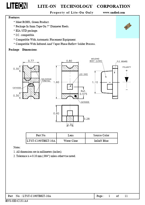
Page : 7 of 11
LITE-ON TECHNOLOGY CORPORATION
Property of Lite-On Only
Notes: 1. Empty component pockets sealed with top cover tape. 2. 7 inch reel-3000 pieces per reel. 3. Minimum packing quantity is 500 pcs for remainders. 4. The maximum number of consecutive missing lamps is two. 5. In accordance with ANSI/EIA 481-1-A-1994 specifications.
Suggest Soldering Pad Dimensions
Package Dimensions Of Tape And Reel
Notes: 1. All dimensions are in millimeters (inches).
Part No. : LTST-C190TBKT-10A BNS-OD-C131/A4
LITE-ON TECHNOLOGY CORPORATION
Property of Lite-On Only Features
* Meet ROHS, Green Product. * Package In 8mm Tape On 7" Diameter Reels. * EIA STD package. * I.C. compatible. * Compatible With Automatic Placement Equipment. * Compatible With Infrared And Vapor Phase Reflow Solder Process.
LTST-C190GKT中文资料
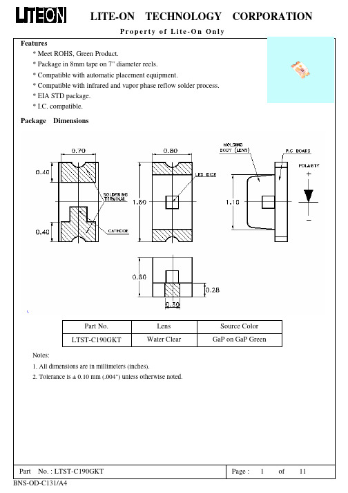
single wavelength which defines the color of the device.
¡
d is derived from the CIE chromaticity diagram and represents the
Part
No. : LTST-C190GKT
Page :
Pre-heat Pre-heat time Peak temperature Soldering time 120~150°C 120 sec. Max. 260°C Max. 5 sec. Max.
CAUTIONS
Wave Soldering
100°C Max. 60 sec. Max. 260°C Max. 10 sec. Max.
(2) Suggestion IR Reflow Profile For Pb Free Process
Part
No. : LTST-C190GKT
Page :
3
of
11
BNS-OD-C131/A4
LITE-ON TECHNOLOGY CORPORATION
Property of Lite-On Only Electrical Optical Characteristics Symbol At Ta=25к Min. Typ. Max. Unit Test Condition
Temperature
Part
No. : LTST-C190GKT
Page :
6
of
11
BNS-OD-C131/A4
LITE-ON TECHNOLOGY CORPORATION
Property of Lite-On Only Cleaning Do not use unspecified chemical liquid to clean LED they could harm the package. If clean is necessary, immerse the LED in ethyl alcohol or in isopropyl alcohol at normal temperature for less one minute. Suggest Soldering Pad Dimensions
神舟电脑 笔记本电脑 说明书

笔记本电脑用户手册深圳市神舟电脑有限公司注意本使用者手册中的信息若有变更恕不另行通知。
制造商或经销商不对本手册中的错误或遗漏处负责,也不对任何可能导因于本手册之执行或使用的必然性损坏情形负责。
本使用者手册中的信息受到著作权法的保护。
未经著作权拥有者之事前书面授权,本手册中之任何部分皆不可以任何形式影印或重制。
Copyright 2005年9月All Rights Reserved.Microsoft及Windows是Microsoft Corporation的注册商标。
DOS、Windows 95/98/ME/2000/NT/XP是Microsoft Corporation的商标。
本手册中所引用之产品名称为其各自拥有者/公司之商标及/或注册商标。
本手册中对于软件的介绍是在授权合约范围许可之下进行的。
其软件仅可在符合合约条件的情形下予以使用或复制。
目录前言符号及惯例保护您的笔记型计算机 - 避免滥用的情形及不佳的环境各节摘要1. 基本介绍性能特色 ……………………….…………………..(1-2)系统概观 ……………………….…………….…….(1-4)俯视图 ………………………………………(1-4)后视图 ………………………………………(1-6)左视图 …………….………………..……….(1-7)右视图 …………………………………..…..(1-8)仰视图 …………………….………………. (1-9)交流电整流器 ……………………………..(1-10) 键盘功能 ………………………………..….…….(1-11)窗口快速键 …………………………..……(1-11)内建数字键盘 ……………………….….…(1-11) 触控板 …………………………………….….…..(1-12)显示子系统 ……………………………….….…..(1-13)调整屏幕的亮度 ………………………..…(1-13)延长显示器的寿命 …………………..……(1-13)开启及关闭液晶显示屏 ………………..…(1-14) 音效设备 ………………………………..….….…(1-15)手动调整音量 ………………………....….(1-15)在使用Windows时调整音量…….…...….(1-15)录音功能 ………………………….…...….(1-15)以太/局域网络控制器 ……………………….…(1-16) 2. 电池电源及电源管理电池组 ……………………………………….….….(2-2)锂电池 …………………………………...….(2-2)有关电池警告的动作 ………………….…...(2-3) 电池放电及充电时间 …………………………...…(2-4)检查电池电量 …………………………………...…(2-4)延长电池寿命及使用周期 ……………….……..…(2-5)使用窗口的电源选项 …………………………...…(2-6)窗口内的电源配置 …………………………(2-6)暂停模式 ……………………………………(2-8)电源按钮的设置 …………………………..(2-10)低电源警告 ………………….…………….(2-11)电源选项快速键 ………………………..…(2-12) 3. 疑难排解.附录A 产品规格附录B 服务保修指南前言使用本手册本使用者手册中包含了关于笔记型计算机、硬件与软件设定信息、疑难排解及技术规格的一般性信息。
3色灯LTST-C19HE1WT-H
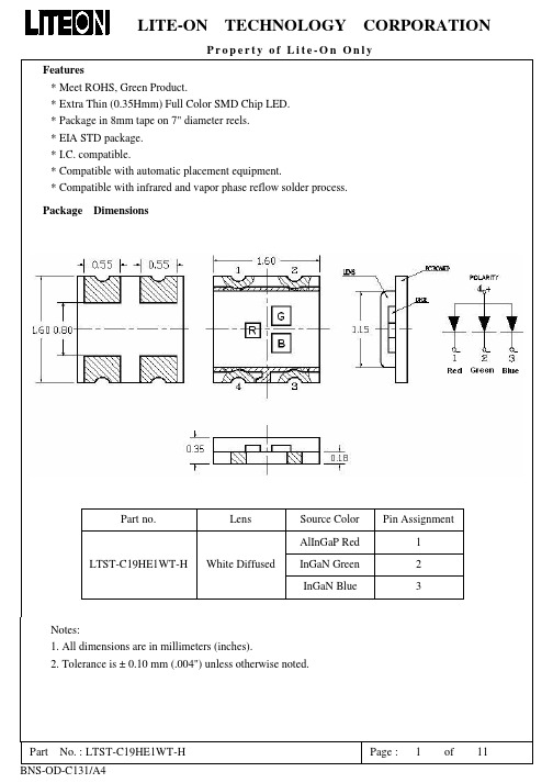
Package Dimensions Of Tape And Reel
Notes: 1. All dimensions are in millimeters (inches).
Part
No. : LTST-C19HE1WT-H
Page :
7
of
11
BNS-OD-C131/A4
LITE-ON TECHNOLOGY CORPORATION
Tolerance on each Intensity bin is +/-15% Luminous Intensity Bin Code S Color : Green , Unit : mcd @20mA Min. 160.0 Tolerance on each Intensity bin is +/-15% Luminous Intensity Bin Code Q R Color : Red , Unit : mcd @20mA Min. 85.0 145.0 Tolerance on each Intensity bin is +/-15% Max. 145.0 240.0 Max. 280.0
Property of Lite-On Only Electrical Optical Characteristics Symbol MIN. Luminous Intensity IV TYP. MAX. Viewing Angle Peak Emission Wavelength 2θ1/2 λPeak TYP. TYP. 468 At Ta=25℃ LTST-C19HE1WT-H Blue 28.0 180.0 Green 160.0 280.0 130 520 632 Red 85.0 240.0 deg nm Note 2 (Fig.6) Measurement @Peak (Fig.1) IF = 20mA Note 3 mcd IF = 20mA Note 1 Test Condition
LTST-C191KRKT中文资料
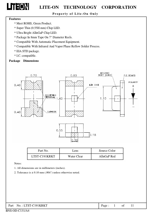
Part
No. : LTST-C191KRKT
Page :
8
of
11
BNS-OD-C131/A4
LITE-ON TECHNOLOGY CORPORATION
Property of Lite-On Only
CAUTIONS
1. Application The LEDs described here are intended to be used for ordinary electronic equipment (such as office equipment, communication equipment and household applications).Consult Liteon’s Sales in advance for information on applications in which exceptional reliability is required, particularly when the failure or malfunction of the LEDs may directly jeopardize life or health (such as in aviation, transportation, traffic control equipment, medical and life support systems and safety devices). 2. Storage The storage ambient for the LEDs should not exceed 30°C temperature or 70% relative humidity. It is recommended that LEDs out of their original packaging are IR-reflowed within one week. For extended storage out of their original packaging, it is recommended that the LEDs be stored in a sealed container with appropriate desiccant, or in a desiccators with nitrogen ambient. LEDs stored out of their original packaging for more than a week should be baked at about 60 deg C for at least 24 hours before solder assembly. 3. Cleaning Use alcohol-based cleaning solvents such as isopropyl alcohol to clean the LED if necessary. 4. Soldering Recommended soldering conditions: Reflow soldering
GEH-3500F型号的GE Power Management制造的ET-16和ET-17指示灯产品

INSTRUCTIONSTYPE ET-16 and ET-17INDICATING LAMPSManual Part Number: GEH-3500FCopyright © 2000 GE Power ManagementGE Power Management 215 Anderson Avenue Markham, Ontario L6E 1B3 CanadaTelephone: (905) 294-6222Fax: (905) 201-2098E-mail:*****************.com Internet: /indsys/pmgGE Power ManagementManufactured under anISO9002 Registered SystemBCS Switchgear Inc.Switchgear | Circuit Breakers | Parts | Tech Support | 888.599.0486Need Help? 888.599.0486GEH-3500FGE Power ManagementType ET-16 and ET-17 Indicating Lamps2CONTENTSPAGE NO.Introduction ..............................................................................................................................................................3Application ................................................................................................................................................................3Features ....................................................................................................................................................................3Ratings ......................................................................................................................................................................4Connections .............................................................................................................................................................4Recommended Panel Assembly .............................................................................................................................4Table 1: ET-16 – Indicating Lamp ...........................................................................................................................4Table 2: ET-16 – for dim-bright application ...........................................................................................................4Table 3: ET-16 – For LEDs .......................................................................................................................................5Table 4: ET-17 – Indicating Lamp ...........................................................................................................................5Table 5: ET-16 Special 127B8177 INDICATING LAMP COMPLETE .....................................................................6Table 6: ET-17 Special 128B1654 INDICATING LAMP COMPLETE .....................................................................6Table 7: Color Cap ...................................................................................................................................................7Ordering table 8: COLOR CAP ................................................................................................................................7TABLE 9: ET-16 LEDs RENEWAL PARTS INFORMATION .. (7)These instructions do not purport to cover all details or variations in equipment nor provide for every possible contingency to be met in connection with installation, operation or maintenance. Should further information be desired or should particular problems arise which are not covered sufficiently for the purchaser's purposes, the matter should be referred to the General Electric Company (USA)To the extent required the products described herein meet applicable ANSI, IEEE and NEMA standards; however, no such assurance is given with respect to local codes and ordinances because they vary greatly. | 888.599.0486Need Help? 888.599.0486GE Power ManagementGEH-3500FType ET-16 and ET-17 Indicating Lamps3INTRODUCTIONThe ET-16 (incandescent and LEDs) and ET-17 (neon) indicating lamps consist of a common receptacle, plug in type resistors and lamps, escutcheon, and color cap. They are available for mounting on switchboard panels up to and including ¼ inch thickness.APPLICATIONThese lamps can be used whenever a panel mounted signal or indicating lamp is desired.The ET-16 is available for either one brilliance or dim bright operation when incandescent lamps are used. ET-16lamps are also available with Light Emitting Diodes (LEDs). The incandescent type can be easily upgraded to the LED type. It only requires acquiring the appropriate color LED and lens cap and inserting into the lamp receptacle.The ET-17 can be used when extra long life is a factor and brilliance is not. It also can be used when low current is desired.FEATURES1.The simple “push-twist” type plug has been adopted for both the bulb and the resistor. This wasaccomplished by incorporating a bayonet base on both components.2. A common receptacle for both the ET-16 and ET-17 coupled with the plug-in resistor and bulb makes iteasy to change on the panel without disassembling.3.The resistor is in series with the bulb, and the ohmic value for the different circuit voltages is designed at80% of the rated bulb voltage to give it longer life. Changing voltages is easily accomplished by changing the series resistor (see listed tables for the proper resistor).4. A short circuit plug is available when a series resistor is not required or if an external resistor is to be used.5.The ET-16 uses GE Catalog No. 1819 for the 24 DC lamp and GE Catalog Number 1835 for the balanceof the ratings. For LED types, long life LEDs (100,000 hours) are specified. Additional features are as follows: reduced heat, resistance to shock and vibration, improved safety, lower current, cost savings, and no cold filament inrush current. The LED lamps come in red, green, and amber colors. White is not an option because a white light LED is not available. ET-17 uses GE Catalog Number B1A.6.Terminals are readily available. They are designed for either AMP “FASTON” type connectors, solder, orscrews.7.Nine basic color caps designed for maximum visibility are available for ET-16 incandescent types. FiveTranslucent caps: red, green, yellow, white; and four transparent caps: amber, red, green, blue, and clear.For ET-16 LED types, only the transparent lens caps are recommended. This is because the transparent lens allows more LED light to pass through than the translucent lens cap used on incandescent lamps.The available colors are as follows: red, green, amber, yellow smoke, clear and blue.ET-17: Because of the special properties of neon, only amber, transparent red, and clear lenses are suitable.The color caps have a knurled OUTSIDE DIAMETER FOR EASY REMOVAL.8.The ET-16 is also available for dim bright applications.9.When special voltage or resistance is required other than those listed, a special lamp may be ordered withthe proper design, or designated series resistor.10.A two-inch insulating washer is supplied with each indicating light. It should be mounted on the inside ofthe panel as illustrated in Figs. 2, 3, and 4. The function of this washer is to provide additional insulation between the terminal and ground (panel) if a surge were to be induced on one of the potential leads.If a bulb other than those listed above is required, the lamp will be furnished less the bulb.Listed tables give some of the specials made available. | 888.599.0486Need Help? 888.599.0486GEH-3500F GE Power ManagementType ET-16 and ET-17 Indicating Lamps4RATINGSResistors ET-16:12.5 WattsET-17: 1 WattBULB DESIGN VOLTAGEDESIGN AMPSCANDLE POWER AVERAGE LIFE(HOURS)1819280.04 A Approx. 0.3425001835550.05 A Approx. 1.15000B1A105-1250.3 mA-15,000CONNECTIONSSee Figure 1A and 1B for typical tell-tale and dim-bright connections.RECOMMENDED PANEL ASSEMBLYThread the pal nut against the shoulder of the receptacle. Install the two-inch insulating washer on the front of the receptacle against the pal nut. Insert the receptacle through the panel and thread the escutcheon nut against panel. Install the color cap and hand tighten (do not force). Turn the escutcheon nut back up against the color cap,then back off ½ to ¾ turn (¾ turn recommended) to give at least 1/64 inch clearance but not more than 1/32 inch clearance between the color cap and escutcheon nut (for up to 3/16 inch panel). For the ¼-inch panel, the color cap will be flush with the escutcheon nut. Tighten the pal nut against panel to 10 to 12 inch-pounds of torque.TABLE 1: ET-16 – INDICATING LAMPCIRCUIT VOLTAGE Resistor 0165A7844Rated volts MIN.volts MAX.volts CATALOG NUMBER(includes lamp, color cap, and resistor)Part No.Ohmic Value Bulb(GE Catalog Number)receptacleColor capcartonoutline24 V DC 48 V DC 125 V DC 250 V DC 120 V AC 240 V AC 22 V 44 V 110 V 220 V 95 V 195 V 28 V 56 V 140 V 280 V 130 V 260 V0116B6708G10116B6708G20116B6708G30116B6708G40116B6708G50116B6708G6123456102002000510019004800181918350116B 6709G 1See ordering Table 60165A 9257P 10165A 7859TABLE 2: ET-16 – FOR DIM-BRIGHT APPLICATIONCIRCUIT VOLTAGE Resistor 0165A9217Ohmic Value Rated volts MIN.volts MAX.volts CATALOG NUMBER (inlcudes lamp, color cap, and resistor)PartNo.Total Tap Bulb (GE Catalog Number)receptacleColor capcartonoutline48 V DC 125 V DC 250 V DC 120 V AC 240 V AC44 V 110 V 220 V 95 V 195 V56 V 140 V 280 V 130 V 260 V0116B8108G20116B8108G30116B8108G40116B8108G50116B8108G612345450255060002450570050170044001600420018350116B 6709G 3See ordering Table 60165A 9257P 20165A 9216GE Power Management GEH-3500FType ET-16 and ET-17 Indicating Lamps5TABLE 3: ET-16 – FOR LEDsReceptacle with Resistor by Voltage LED Lamp by Voltage No.3 - Transparent Color Lens Cap Rated Voltage Min.Max.Catalog No.RatedVoltage Lamp Color Cat. No.Digits Transp.Cap Color Cat. No.Digits 24 DC2228116B6708G4124 DCRed Green Amber R92G92A9248 DC 4456116B6708G4248 DC Red Green Amber R52G52A52125 DC250 DC 110220140280116B6708G43116B6708G44125 DC 250 DC Red Green Amber R53G53A5370 AC 120 AC 130 AC 240 AC559510519576130140260116B6708G47116B6708G45116B6708G48116B6708G4670 AC 120 AC 130 AC 240 ACRed Green AmberR53G53A53Red Green Amber Yellow Smoke Clear NoneR4G4A4Y4S4C4N4Example: Using Table 3 to specify a complete ET-16 LED catalog number for a 24 V DC, Red LED Lamp, red Transparent Color CapReceptacle and Resistor by VoltageLED Lamp Color by VoltageLens Cap by ColorCatalog Number: 116B6708G41 R92 R4TABLE 4: ET-17 – INDICATING LAMPResistor 0165A7956Voltage Range AC/DC Cat. No.*(includes Lamp, color gap,and resistor)Part No.Ohmic Value Bulb (GE Catalog Number)receptacleColor CapCartonOutline110-139140-219220-299300-374375-449450-6000116B6734G10116B6734G20116B6734G30116B6734G40116B6734G50116B6734G6123456200 K 560 K 750 K 1 M 1.2 M 1.6 MB1A0116B 6709G 1see Ordering Table 70165A 9257P 30165A 7955Specify color cap from Table 6 or 7GEH-3500F GE Power ManagementType ET-16 and ET-17 Indicating Lamps6TABLE 5: ET-16 SPECIAL 127B8177INDICATING LAMP COMPLETE1 REQ D of GR. or PT NO. LISTED BELOWRESISTOR Group No*VoltsReceptacleDRG. No.Part No.Value BULB GE Cat. No.Color CapCartonOnline1234567897017140220321252771401300116B 6709G -10165A 78447891021112913750 Ω50 Ω2500 Ω4300 Ω200 Ω3300 Ω5900 Ω2500 Ω2300 Ω1835756NONE 183518191835183518351835** S e e O r d e r i n g T a b l e 60165A 9257P -10165A 7859** 756 Bulb Furnished by CustomerTABLE 6: ET-17 SPECIAL 128B1654INDICATING LAMP COMPLETE1 REQ D of GR. or PART NUMBER LISTED BELOWRESISTOR BULBGroup No*VoltsReceptacle DRG. No.Part No.Value GE Cat. No.ColorCapCartonOnline1210 to 250V AC/DC156 K ΩNE51H **267 to 120V AC0116B 6709G R -10165A 7956880 K ΩNE51 or B1AS e e O r d e r i n g T a b l e 70165A 92570165A 7955** NE51H BULB Furnished by CustomerGE Power Management GEH-3500FType ET-16 and ET-17 Indicating Lamps 7TABLE 7: COLOR CAPCOLOR CAPCAT. NO.COLOR CAT. NO.0116B6708G NONE NONE 0116B6708G*C CLEAR Π208A3768P10116B6708G*R RED ∅208A3768P20116B6708G*G GREEN ∅208A3768P30116B6708G*Y YELLOW ∅208A3768P40116B6708G*W WHITE ∅208A3768P50116B6708G*B BLUE Π208A3768P60116B6708G*A AMBER Π208A3768P70116B6708G*D GREEN Π208A3768P80116B6708G*ERED Π208A3768P9ORDERING TABLE 8: COLOR CAPCOLOR CAPCAT. NO.COLOR CAT. NO.0116B6734G*NONE NONE0116B6734G*C CLEAR Π208A3768P10116B6734G*E RED Π208A3768P90116B6734G*AAMBER Π208A3768P7HOW TO ORDER:Order by the complete Catalog Number and specify color cap. To order renewal parts for ET-16 LEDs or for Incandescent ET16 conversion to LEDs, use the following table:TABLE 9: ET-16 LEDs RENEWAL PARTS INFORMATIONReceptacle: 116B6709G1Resistor 165A7844PRatedVoltagePart No.Ohmic Value LampColor LED Lamp 286A5442P GE Part mp Marking Lens Cap 286A5443PLens Color24 DC 110Red Green Amber R92G92A921819L2R 1819L2G 1819L2A 48 DC 2200Red Green Amber R52G52A521835L2R 1835L2G 1835L2A 125 DC 250 DC 3420005100Red Green Amber R53G53A531835L3R 1835L3G 1835L3A 70 AC 120 AC 130 AC 240 AC75136750190023004800Red Green AmberR53G53A531835L3R 1835L3G 1835L3ARed Green Amber Yellow Smoke ClearR4G4A4Y4S4C4GEH-3500F GE Power ManagementType ET-16 and ET-17 Indicating Lamps8Figure 1 (0246A3685[1]): TYPICAL TELL-TALE AND DIM-BRIGHT CONNECTIONGE Power Management GEH-3500FType ET-16 and ET-17 Indicating Lamps9Figure 2 (0165A9216[4]): OUTLINE AND PANE DRILLING FOR TYPE ET-16 INDICATING LAMP WITH TAPRESISTOR FOR DIM BRIGHT OPERATIONSGEH-3500F GE Power ManagementType ET-16 and ET-17 Indicating Lamps10Figure 3 (0165A7859[6]): OUTLINE AND PANEL DRILLING FOR TYPE ET-16 INDICATING LAMPGE Power Management GEH-3500F Type ET-16 and ET-17 Indicating Lamps11Figure 4 (0165A7955[6]): OUTLINE AND PANEL DRILLING FOR NEON INDICATING LAMP TYPE ET-17gGE Power Management215 Anderson AvenueMarkham, OntarioL6E 1B3 CanadaTelephone (905) 294-6222/indsys/pm。
LTST-C190KRKT
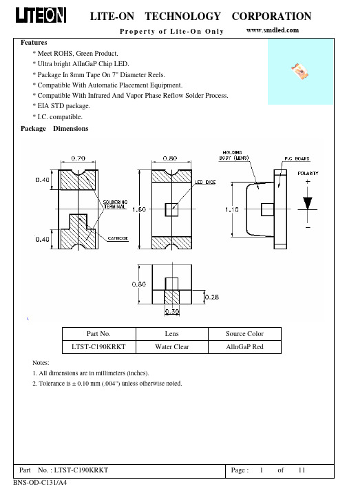
Page : 7 of 11
LITE-ON TECHNOLOGY CORPORATION
Property of Lite-On Only
Notes: 1. Empty component pockets sealed with top cover tape. 2. 7 inch reel-3000 pieces per reel. 3. Minimum packing quantity is 500 pcs for remainders. 4. The maximum number of consecutive missing lamps is two. 5. In accordance with ANSI/EIA 481-1-A-1994 specifications.
LTST-C190JFKT
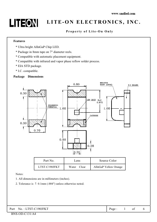
( ) +8 ! % 7 *4--- 4' : ""$ " %
! 6 ! (& 5 6+*+* *+,,6 $
(
!"! !"!!"#!$%& ' $! ""#()&*%!
主营的产品有:SMD LED 发光二极管 色彩有:红、橙、黄、绿、 蓝、白、紫、粉红、单色双色及三色,封装有:0402、0603、0802、 0805、1204、1206、3528、5050、3020、3014、2835、3535、335、 020、正面发光及侧面发光等…
主要应用:照明灯具、灯光亮化装饰工程、玩具礼品、背光显示、 荧光验证防伪、手机、家电、MP3、手电筒、汽车、圣诞树、霓虹灯 等…
7
' '(
7
:
='"
56*
:5
75=.7
, $! $
(
7
= ;=<@A
*"!*!!1!" * !% !% ;!$"B! !% ,,C!" % :>1,$*6 ' 0'!%;; C! %!$%%*"!*!!1!% ;% C! *"!*!!1 4% "! 6%2 ! !6 ;"%:>$%" !$!1 ! " ,% ! 6%%!$% ;!%$;% 6!$
山特c1ks参数

山特c1ks参数1. 引言山特(Sante)是一家专注于网络设备的制造商,其产品涵盖了交换机、路由器等多个领域。
其中,C1KS是山特推出的一款高性能交换机系列产品。
本文将详细介绍C1KS交换机的参数及其功能。
2. C1KS交换机概述C1KS交换机是山特公司为满足企业和数据中心对高可靠性、高性能网络设备的需求而推出的一款产品。
它采用了先进的硬件设计和软件技术,具备卓越的性能和可靠性。
C1KS交换机支持多种接口类型,包括千兆以太网口(10/100/1000BASE-T)、万兆以太网口(10GBASE-T/SFP+)等,以满足不同场景下的需求。
同时,它还支持POE (Power over Ethernet)功能,可以为无线AP、IP摄像头等设备提供电力供应。
3. 主要参数3.1 性能参数•转发容量:C1KS交换机具有强大的转发能力,支持高达XXXGbps的转发容量,可以满足大规模数据传输和处理需求。
•转发速率:C1KS交换机支持高速数据传输,其转发速率可达XXXMpps(百万数据包每秒),能够快速处理大量的数据流。
•缓存容量:C1KS交换机内置大容量缓存,可提供XXXMB的缓存容量,有效降低网络延迟和丢包率。
3.2 接口参数•电口类型:C1KS交换机支持多种电口类型,包括10/100/1000BASE-T以太网口和10GBASE-T/SFP+万兆以太网口。
用户可以根据实际需求选择合适的接口类型。
•光口类型:C1KS交换机还提供多种光纤接口选项,如SFP、SFP+等,可与其他设备进行光纤连接。
•POE功能:C1KS交换机支持POE功能,可以为无线AP、IP摄像头等设备提供电力供应。
3.3 软件参数•系统版本:C1KS交换机搭载了山特自主研发的操作系统,并提供了多个版本选择。
用户可以根据实际需求选择合适的系统版本。
•管理方式:C1KS交换机支持多种管理方式,包括Web界面、命令行接口(CLI)等。
用户可以通过这些方式对交换机进行配置和管理。
- 1、下载文档前请自行甄别文档内容的完整性,平台不提供额外的编辑、内容补充、找答案等附加服务。
- 2、"仅部分预览"的文档,不可在线预览部分如存在完整性等问题,可反馈申请退款(可完整预览的文档不适用该条件!)。
- 3、如文档侵犯您的权益,请联系客服反馈,我们会尽快为您处理(人工客服工作时间:9:00-18:30)。
IV
Viewing Angle
2θ1/2
C190KRKT
130
deg
Peak Emission Wavelength
λP
C190KRKT
639
nm
Dominant Wavelength
λd
C190KRKT
631
nm
Spectral Line Half-Width
Δλ
C190KRKT
20
nm
Forward Voltage
Part No. LTST-C190KRKT
Notes: 1. All dimensions are in millimeters (inches).
Lens Water Clear
Source Color AllnGaP Red
2. Tolerance is ± 0.10 mm (.004") unless otherwise noted.
Package Dimensions Of Tape And Reel
Notes: 1. All dimensions are in millimeters (inches).
Part
No. : LTST-C190KRKT
Page :
6
of
10
BNS-OD-C131/A4
LITE-ON
TECHNOLOGY
LITE-ON
Features
TECHNOLOGY
CORPORATION
Property of Lite-On Only
* Ultra bright AlInGaP Chip LED. * Package in 8mm tape on 7" diameter reels. * Compatible with automatic placement equipment. * Compatible with infrared and vapor phase reflow solder process. * EIA STD package. * I.C. compatible. Package Dimensions
CORPORATION
Property of Lite-On Only
Notes: 1. Empty component pockets sealed with top cover tape. 2. 7 inch reel-3000 pieces per reel. 3. Minimum packing quantity is 500 pcs for remainders. 4. The maximum number of consecutive missing lamps is two. 5. In accordance with ANSI/EIA 481-1-A-1994 specifications.
Part
No. : LTST-C190KRKT
Page :
3
of
10
BNS-OD-C131/A4
LITE-ON
TECHNOLOGY
CORPORATION
Property of Lite-On Only
Bin Code List
Luminous Intensity Bin Code M N P Q R Min. 18.0 28.0 45.0 71.0 112.0 Unit : mcd @20mA Max. 28.0 45.0 71.0 112.0 180.0
Pre-heat Pre-heat time Peak temperature Soldering time 120~150°C 120 sec. Max. 240°C Max. 10 sec. Max.
Wave Soldering
100°C Max. 60 sec. Max. 260°C Max. 10 sec. Max.
Part
No. : LTST-C190KRKT
Page :
7
of
10
BNS-OD-C131/A4
LITE-ON
TECHNOLOGY
CAUTIONS
CORPORATION
Property of Lite-On Only
1. Application The LEDs described here are intended to be used for ordinary electronic equipment (such as office equipment, communication equipment and household applications).Consult Liteon’s Sales in advance for information on applications in which exceptional reliability is required, particularly when the failure or malfunction of the LEDs may directly jeopardize life or health (such as in aviation, transportation, traffic control equipment, medical and life support systems and safety devices). 2. Storage The storage ambient for the LEDs should not exceed 30°C temperature or 70% relative humidity. It is recommended that LEDs out of their original packaging are IR-reflowed within one week. For extended storage out of their original packaging, it is recommended that the LEDs be stored in a sealed container with appropriate desiccant, or in a desiccators with nitrogen ambient. LEDs stored out of their original packaging for more than a week should be baked at about 60 deg C for at least 24 hours before solder assembly. 3. Cleaning Use alcohol-based cleaning solvents such as isopropyl alcohol to clean the LED if necessary. 4. Soldering Recommended soldering conditions: Reflow soldering
Soldering iron
Temperature Soldering time 300°C Max. 3 sec. Max. (one time only)
Pre-heat Pre-heat time Solder wave Soldering time
5. Drive Method An LED is a current-operated device. In order to ensure intensity uniformity on multiple LEDs connected in parallel in an application, it is recommended that a current limiting resistor be incorporated in the drive circuit, in series with each LED as shown in Circuit A below. Circuit model A
Parameter
Power Dissipation Peak Forward Current (1/10 Duty Cycle, 0.1ms Pulse Width) DC Forward Current Derating Linear From 25°C Reverse Voltage Operating Temperature Range Storage Temperature Range Wave Soldering Condition Infrared Soldering Condition Vapor Phase Soldering Condition Suggest IR Reflow Condition :
Unit
mW mA mA mA/°C V
Part
No. : LTST-C190KRKT
Page :
2
of
10
BNS-OD-C131/A4
LITE-ON
Electrical Parameter
Luminous Intensity
TECHNOLOGY
At Ta= 25℃ Min.
18.0
CORPORATION
Property of Lite-On Only Optical Characteristics Symbol
Part No.
LTSTC190KRKT
Typ.
54.0
Max.
Unit
mcd
Test Condition
IF = 20mA Note 1 Note 2 (Fig.6) Measurement @Peak (Fig.1) Note 3
VF
C190KRKT
2.0
2.4
V
IF = 20mA
