LB.Socket.Probe录系统
英文版 sockettest
1. 什么是sockettestSockettest是一个用于测试网络通信的工具,它可以帮助开发人员检查TCP和UDP连接,发送和接收数据,以及查看服务器和客户端之间的通信情况。
它提供了简单直观的界面,方便用户进行测试和调试。
2. 安装和运行sockettest要使用Sockettest,用户需要首先下载并安装软件。
安装完成后,用户可以打开软件并开始使用。
软件界面清晰简洁,操作简单方便。
3. Sockettest的主要功能Sockettest提供了丰富的功能,可以满足用户在网络通信测试中的各种需求。
主要功能包括:- TCP连接测试:用户可以输入服务器的IP位置区域和端口号,进行TCP连接测试。
软件会显示连接成功或失败的结果,并显示连接的延迟时间。
- UDP连接测试:用户可以输入服务器的IP位置区域和端口号,进行UDP连接测试。
软件会显示连接成功或失败的结果,并显示连接的延迟时间。
- 数据发送和接收:用户可以自定义发送的数据内容和格式,软件会显示发送和接收的数据,并能够进行数据解析和分析。
- 数据日志记录:软件会记录用户进行的各项操作和测试结果,方便用户进行回顾和分析。
4. Sockettest的优点和适用场景Sockettest具有以下优点:- 界面简洁直观,操作便捷,适合各种用户进行测试和调试。
- 提供了丰富的功能和参数设置,满足了用户在网络通信测试中的各种需求。
- 日志记录功能完善,方便用户进行操作回顾和结果分析。
Sockettest适用于以下场景:- 研发人员在开发和调试网络通信程序时,可以使用Sockettest进行连接测试和数据传输测试。
- 网络管理员在维护和监控网络设备时,可以使用Sockettest进行设备连接测试和数据传输测试。
- 测试人员在进行网络通信测试时,可以使用Sockettest进行各种测试操作。
5. 结语Sockettest是一个功能丰富、操作简便的网络通信测试工具,可以帮助用户检查TCP和UDP连接,发送和接收数据,方便用户进行测试和调试。
Probe_Assistant使用简介

Probe、Assistant 使用简介
C&Wi售前网络规划部
四川移动TD-LTE项目组培训材料 2013年9月14日
HUAWEI TECHNOLOGIES CO., LTD.
Huawei Confidential
掌握测试和数据分析的基本知识 掌握Probe软件测试方法 掌握Assistant软件数据分析方法 了解一般问题的定位和解决方法
Huawei Confidential
Huawei GENEX Series
GENEX Nastar Network Performance Analysis System
GENEX Probe GENEX Assistant Test & Post-Process Tools
Downlink + Uplink
性能/配置/CHR/用户 跟踪/RTWP/
工程参数等综合分析
GENEX
Nastar
集成多种优化/规划辅助工具
分析结论共享
GENEX Probe Qualcomm
HUAWEI RNC
多种测试数据
GENEX Assistant
iManagerTM M2000 获取测试数据
eNB
eNB
GENEX Probe
9.按分析集查看分析报告
10.事件下钻进行问题定位
11.查看专题分析结果 查看KPI/IE
组合查询
新建工程
配置工程
导入工参
导入地图
选择导入的数据 设置监控目录
执行导入分析
自动导入分析
建立分析集 分析集
以分析集为单位进行查 看KPI,报告,专题等
HUAWEI TECHNOLOGIES CO., LTD.
hpsocket getremoteaddress 用法-概述说明以及解释

hpsocket getremoteaddress 用法-概述说明以及解释1.引言1.1 概述在引言部分的概述中,我们将对HP-Socket的getremoteaddress 函数进行介绍。
HP-Socket是一个基于C++的高性能网络库,提供了丰富的网络编程功能和可靠的数据传输机制。
getremoteaddress函数是HP-Socket中的一个重要函数,它用于获取远程客户端的IP地址和端口号。
在网络编程中,获取远程客户端的IP地址和端口号是非常常见且重要的操作。
通过获取远程客户端的地址信息,我们可以实现诸如用户追踪、连接管理、安全验证等功能。
而getremoteaddress函数就是HP-Socket 库提供的用于获取远程客户端地址信息的接口,非常方便且实用。
通过调用getremoteaddress函数,我们可以获取到客户端连接的IP 地址和端口号,可以根据这些信息进行灵活的处理和管理。
我们可以根据获取到的远程地址信息进行用户追踪和记录,根据不同的远程地址做出不同的策略判断,也可以通过远程地址实现连接的管理和统计。
此外,通过获取远程客户端的地址信息,我们还可以进行安全验证。
例如,我们可以通过检查远程客户端的IP地址合法性来判断该连接是否为合法的客户端连接,从而加强系统的安全性。
总之,getremoteaddress函数是HP-Socket库中非常重要的一个函数,它提供了获取远程客户端地址信息的便利和灵活性。
我们可以利用这个函数实现诸多功能,包括用户追踪、连接管理、安全验证等。
对于使用HP-Socket库开发网络应用的开发者来说,熟练掌握getremoteaddress 函数的使用方法是非常重要的。
在接下来的文章中,我们将详细介绍getremoteaddress函数的使用方法和示例。
1.2文章结构目的部分的内容可以按照以下方式进行编写:1.3 目的本文旨在介绍并详细解释hpsocket网络库中的getremoteaddress 函数的用法。
uretprobe 原理 -回复

uretprobe 原理-回复uretprobe是Linux系统中的一种动态追踪技术,用于在运行时跟踪系统中的函数调用。
本文将介绍uretprobe的原理,包括其工作流程、具体实现方法以及应用实例等。
一、uretprobe的概述uretprobe是Linux系统中的一个动态追踪技术,它可以在函数返回时执行用户指定的代码。
它的原理是利用内核提供的ftrace功能,在函数返回时设置一个断点,并在断点处执行用户指定的代码。
uretprobe通过在目标函数返回时插入额外的代码,可以实现函数调用的跟踪和分析。
二、uretprobe的工作流程uretprobe的工作流程可以总结为以下几个步骤:1. 选择目标函数:首先,用户需要选择一个目标函数进行跟踪。
目标函数是用户希望跟踪的函数,在函数返回时将执行用户指定的代码。
2. 编写钩子函数:用户需要编写一个钩子函数,用于在目标函数返回时执行。
钩子函数可以是一段C代码或者一个脚本,它在目标函数返回时被调用。
3. 注册uretprobe:使用系统提供的工具,将用户编写的钩子函数注册到目标函数上。
注册的过程中需要指定目标函数的地址和钩子函数的地址。
4. 执行跟踪:一旦uretprobe被注册成功,每当目标函数返回时,钩子函数就会被调用。
用户可以在钩子函数中执行任意代码,并对函数的返回值进行分析。
三、uretprobe的具体实现方法uretprobe的具体实现方法主要依赖于Linux内核提供的ftrace功能。
下面将阐述uretprobe的实现方法:1. ftrace的背景介绍:Linux内核提供了一种叫做ftrace的功能,用于对内核的函数调用进行跟踪。
ftrace可以通过在函数的入口和出口设置断点,记录函数调用的信息。
2. uretprobe的原理:uretprobe是在ftrace的基础上扩展而来的。
在注册uretprobe时,用户需要指定目标函数的地址,并提供一个钩子函数的地址。
socket测试方案

Socket测试方案1. 引言Socket是一种在计算机网络中用于实现进程间通信的一种机制。
在网络通信的应用场景中,Socket是一种常用的通信方式。
为了确保Socket通信的可靠性和稳定性,有必要进行Socket测试以验证其性能和功能。
本文档将介绍一种基本的Socket测试方案,其中包括测试目的、测试环境、测试步骤和测试结果的分析等内容。
2. 测试目的Socket测试的主要目的是验证Socket通信的性能和稳定性,具体包括以下几个方面:1.确保Socket连接的建立和断开正常。
2.验证Socket数据传输的可靠性和稳定性。
3.评估Socket通信的性能,包括延迟、吞吐量和并发性能等指标。
通过Socket测试,可以从整体上了解应用程序的网络通信性能,发现潜在的问题并进行相应的优化。
3. 测试环境在进行Socket测试之前,需要设置好适当的测试环境,包括以下几个方面:1.服务器端和客户端的设备,可以是物理机或者虚拟机。
2.操作系统,可以是Windows、Linux或者其他适用的操作系统。
3.网络环境,确保服务器端和客户端能够正常通信。
4. 测试步骤4.1 创建服务器端首先需要创建一个服务器端的Socket程序,负责监听客户端的连接请求并进行处理。
可以使用Java、Python等编程语言来实现服务器端。
以下为一个使用Python的示例代码:import socket# 创建一个TCP socket对象server_socket = socket.socket(socket.AF_INET, socket.SOCK_STREAM)# 绑定服务器端的IP地址和端口号server_address = ('localhost', 8080)server_socket.bind(server_address)# 监听客户端的连接请求server_socket.listen(5)while True:# 接受客户端的连接请求client_socket, client_address = server_socket.accept() # 处理客户端请求的逻辑# ...# 关闭客户端的连接client_socket.close()# 关闭服务器端的socket对象server_socket.close()4.2 创建客户端接下来需要创建一个客户端的Socket程序,负责向服务器端发送请求并接收服务器端的响应。
LWIP之SOCKET的实现

LWIP之SOCKET的实现LWIP(Lightweight IP)是一个开源的、轻量级的TCP/IP协议栈实现,旨在在资源受限的嵌入式系统中提供高效可靠的网络通信功能。
LWIP提供了一个类似于BSD的套接字API,使开发人员可以在嵌入式系统中使用熟悉的套接字编程模型进行网络通信。
在LWIP中,SOCKET的实现主要涉及以下几个方面:1. 配置和初始化:首先,需要在LWIP的配置文件(lwipopts.h)中启用套接字(SOCKET)功能。
可以通过定义`LWIP_SOCKET`宏来启用SOCKET功能。
接下来,需要在应用程序中调用`lwip_init(`函数初始化LWIP协议栈。
2. 创建和绑定Socket:使用`socket(`函数可以创建一个套接字,并返回一个套接字描述符(Socket Descriptor)。
该函数接收三个参数:domain(协议簇,例如AF_INET表示IPv4)、type(套接字类型,例如SOCK_STREAM表示TCP)、protocol(协议类型,例如IPPROTO_TCP表示TCP协议)。
创建套接字后,可以使用`bind(`函数将套接字与具体的本地IP地址和端口绑定起来。
`bind(`函数接收三个参数:socket(套接字描述符)、address(一个指向本地IP地址和端口的结构体指针)和address_len(结构体长度)。
3. 连接和监听:对于TCP套接字,可以使用`connect(`函数向目标IP地址和端口发起连接请求。
`connect(`函数接收三个参数:socket(套接字描述符)、address(一个指向目标IP地址和端口的结构体指针)和address_len(结构体长度)。
对于服务器端,可以使用`listen(`函数开始监听指定的端口。
`listen(`函数接收两个参数:socket(套接字描述符)和backlog(等待连接队列的最大长度)。
4. 数据收发:使用`send(`函数可以向已连接的套接字发送数据。
Linxu内核参数详解

Linxu内核参数详解1. #表⽰SYN队列的长度,默认为1024,加⼤队列长度,可以容纳更多等待连接的⽹络连接数。
2. net.ipv4.tcp_max_syn_backlog = 655363.4. #每个⽹络接⼝接收数据包的速率⽐内核处理这些包的速率快时,允许送到队列的数据包的最⼤数⽬5. dev_max_backlog = 327686.7. #默认128,这个参数会影响到所有AF_INET类型socket的listen队列8. net.core.somaxconn = 327689.10. #系统套接字写默认缓冲区11. net.core.wmem_default = 838860812.13. #系统套接字读默认缓冲区14. net.core.rmem_default = 838860815.16. #系统套接字读最⼤缓冲区17. net.core.rmem_max = 1677721618.19. #系统套接字写最⼤缓冲区20. net.core.wmem_max = 1677721621.22. #此参数与net.ipv4.tcp_wmem都是⽤来优化TCP接收/发送缓冲区,包含三个整数值,分别是:min,default,max:23. #tcp_rmem:min表⽰为TCP socket预留⽤于接收缓冲的最⼩内存数量,default为TCP socket预留⽤于接收缓冲的缺省内存数量,max⽤于TCP socket接收缓冲的内存最⼤值。
24. #tcp_wmem:min表⽰为TCP socket预留⽤于发送缓冲的内存最⼩值,default为TCP socket预留⽤于发送缓冲的缺省内存值,max⽤于TCP socket发送缓冲的内存最⼤值。
25. net.ipv4.tcp_rmem=4096 87380 419430426. net.ipv4.tcp_wmem=4096 16384 419430427.28. #时间戳可以避免序列号的卷绕。
华擎 X99 OC Formula 主板说明书
182X99 OC Formula1.2 规格平台• EATX 规格尺寸• 8 层PCB• 4 x 2 盎司纯铜• 高密度防潮纤维电路板CPU• 支持适用于 LGA 2011-3 Socket 的 Intel® Core TM i7 andXeon® 18 核处理器系列• 高性能数字供电• 12相CPU供电设计 (最高支持 1300w)• 支持 Intel® Turbo Boost 2.0 技术• 支持異步超頻技術芯片集• Intel® X99内存• 支持四通道DDR4 内存技术• 8 x DDR4 DIMM槽• 支持 DDR4 3400+(OC)*/2933+(OC)/2800(OC)/2400(OC)/2133/1866非 ECC,非缓冲内存* 请参阅华擎网站上的 Memory Support List(内存支持列表)了解详情。
(/)• 支持非 ECC x8 (8位) RDIMM (寄存型 DIMM)/x8 (8 位)UDIMM• 通过 LGA 2011-3 Socket 中的 Intel® Xeon® 处理器 E5 系列,支持DDR4 ECC x8 (8 位) RDIMM/x8 (8 位) UDIMM• 支持系统内存容量:128GB(见“注意”)• 支持 Intel® Extreme Memory Proile (XMP)2.0扩充槽• 5 x PCI Express 3.0 x16 槽 (PCIE1/PCIE2/PCIE3/PCIE4/PCIE5: 单 - x16 (PCIE1);双 - x16 (PCIE1) / x16 (PCIE4);三 - x8 (PCIE1) / x8 (PCIE2) / x16 (PCIE4);四 - x8 (PCIE1)/ x8 (PCIE2) / x8 (PCIE4) / x8 (PCIE5))* 如果您安装 28 通道的 CPU,则 PCIE1/PCIE2/PCIE3/PCIE4将以 16倍速/0倍速/4倍速/ 8倍速或8倍速/8倍速/4倍速/8倍速运行, PCIE5 将被禁用。
单片机proteus元件库元件名称

元件库元件名称及中英对照AND与门ANTENNA天线BATTERY直流电源BELL铃,钟BVC同轴电缆接插件BRIDEG 1整流桥(二极管)BRIDEG 2整流桥(集成块)BUFFER缓冲器BUZZER蜂鸣器CAP电容CAPACITOR电容CAPACITOR POL有极性电容CAPVAR可调电容CIRCUIT BREAKER熔断丝COAX同轴电缆CON插口CRYSTAL晶体整荡器DB并行插口DIODE二极管DIODE SCHOTTKY稳压二极管DIODE VARACTOR变容二极管DPY_3-SEG 3段LEDDPY_7-SEG 7段LEDDPY_7-SEG_DP 7段LED(带小数点)ELECTRO电解电容FUSE熔断器INDUCTOR电感INDUCTOR IRON带铁芯电感INDUCTOR3可调电感JFET N N沟道场效应管JFET P P沟道场效应管LAMP灯泡LAMP NEDN起辉器LED发光二极管METER仪表MICROPHONE麦克风MOSFET MOS管MOTOR AC交流电机MOTOR SERVO伺服电机NAND与非门NOR或非门NOT非门NPN NPN三极管NPN-PHOTO感光三极管OPAMP运放OR或门PHOTO感光二极管PNP三极管NPN DAR NPN三极管PNP DAR PNP三极管POT滑线变阻器PELAY-DPDT双刀双掷继电器RES1.2电阻RES3.4可变电阻RESISTOR BRIDGE ?桥式电阻RESPACK ?电阻SCR晶闸管PLUG ?插头PLUG AC FEMALE三相交流插头SOCKET ?插座SOURCE CURRENT电流源SOURCE VOLTAGE电压源SPEAKER扬声器SW ?开关SW-DPDY ?双刀双掷开关SW-SPST ?单刀单掷开关SW-PB按钮THERMISTOR电热调节器TRANS1变压器TRANS2可调变压器TRIAC ?三端双向可控硅TRIODE ?三极真空管VARISTOR变阻器ZENER ?齐纳二极管DPY_7-SEG_DP数码管SW-PB开关元件名称中文名说明7407驱动门1N914二极管74Ls00与非门74LS04非门74LS08与门74LS390 TTL双十进制计数器7SEG 4针BCD-LED输出从0-9对应于4根线的BCD码7SEG 3-8译码器电路BCD-7SEG转换电路AlterNATOR交流发电机AMMETER-MILLI mA安培计AND与门BATTERY电池/电池组BUS总线CAP电容CAPACITOR电容器CLOCK时钟信号源CRYSTAL晶振pim串口D-FLIPFLOP D触发器FUSE保险丝GROUND地LAMP灯LED-RED红色发光二极管LM016L 2行16列液晶可显示2行16列英文字符,有8位数据总线D0-D7,RS,R/W,EN三个控制端口(共14线),工作电压为5V。
linux socket debug方法

Linux Socket Debug方法是指在Linux系统中,利用Socket API对网络通信进行调试的方法。
通过Socket Debug,开发人员可以在通信过程中捕获和分析数据包,以检查网络连接是否正常、数据传输是否正确。
这对于排查网络故障和优化网络性能非常有帮助。
使用Socket Debug的一般步骤包括:
1.创建一个Socket,使用socket()函数创建一个Socket,指定使用TCP或
UDP协议。
2.绑定Socket,使用bind()函数将Socket与本地IP地址和端口绑定。
3.使Socket进入监听状态,等待客户端连接,使用listen()函数。
4.接受客户端的连接请求,并返回一个新的Socket,使用accept()函数。
5.从客户端接收数据,并进行分析,使用recv()函数。
6.向客户端发送数据,使用send()函数。
7.在数据传输完成后,关闭Socket,使用close()函数。
以上信息仅供参考,可以查阅关于Linux Socket Debug的文献资料以获取更全面准确的信息。
MP250 磨具机触摸探头系统说明书

Data sheet H-5500-8200-04-A /mp250The world’s first strain gauge inspection probe for grinding machines,using Renishaw’s patentedtechnology .System componentsMP250 probeAn ultra compact touch probe for grinding machines that sets new standards for the precision measurement of 3D partgeometries, whilst offering all the standard probing benefits of reduced set-up times, reduced scrap and improved process control.HSI interfaceHardwired transmission interface which conveys andprocesses signals between the inspection probe and the CNC machine control.FS1 and FS2 probe holdersProvide a robust mounting position for the probe and a fully screened hardwired connection between the probe and the interface.PSU3 power supplyUsed when a 12 V to 30 V power supply is not available on the CNC machine.System featuresHigh accuracyPatentedstrain gauge technology with ultra-low pre-travel variation provides high accuracy, even when the application requires long styli. This allows sub-micron 3D performance on a range of applications which demand high precision measurement such as contoured surfaces, for example gear teeth and cutting tools. Probe calibration times are reduced compared to standard probes. Highly repeatableImproved repeatability in all probing directions compared to standard probes.Ultra compactMeasuring only Ø25 mm x 40 mm long, the MP250 is ideal for grinding machine applications with restricted space.Robust and reliableRenishaw’s MP250 sets new standards for reliability and is designed to resist harsh machine conditions.The MP250 probe is sealed for use within the grindingmachine’s hostile environment, where it is subject to particle laden coolant. The diaphragm material is resistant to coolants and elevated temperatures.The MP250 offers resistance to shock and false triggering through the use of digital filtering.Solid-state strain gauge technology reduces the effects of mechanical wear resulting in greatly increased life compared to other probes.SALES & SERVICE: A Tech Authority, Inc. 13745 Stockton Ave. Chino CA 91710 909-614-4522************************Data sheet MP250MP250 dimensionsDimensions given in mm (in)42.7 (1.68)36 (1.41)M4 stylus13°13°Ø25 (Ø0.98)6.7 (0.26)18 (0.70)Ø7 (Ø0.27)M 16 x 14.7 (0.18)Z overtravel 6.5 (0.25)XY overtravel40.7 (1.59)HSI dimensions8 (3.86)134 (5.28)Probe holder dimensionsØ24.75 (0.975)protect against ingress of chips or coolant when the probe is removed.Two adjusting screws (2.5 mm AF hexagon socket) providing ±4° angular adjustment.Side cable exit Ø 6 mm min.Side cable exit Ø 6 mm min.Ø26 (Ø1.02)22.5 (0.88)4.5 (0.18)M16 x 1 thread8 (0.31)8.2 (0.32)8.0 (0.31)9.4 (0.37)9.4 (0.37)9.2 (0.36)9.2 (0.36)22.03 (0.87)21.98 (0.86)13.8 (0.54)0.3 (0.01) x 45°20.65 (0.812)20.55 (0.809)0.8 (32)20 (0.78)Hole depth (min)30 (1.18) minimumMachining details for mounting hole (FS1)Machining details for mounting hole (FS2)Ø0.1 (0.004)Ø24.75 (0.975)23.0 (0.905)22.9 (0.901)21.0 (0.82)20.8 (0.81)2 (0.8)8 (0.31)60°15°M 22 x 1 t h r e a d20 (0.78)Hole depth (min)30 (1.18) minimum22.5 (0.88)4.5 (0.18)M22 x 1 threadM16 x 1thread2 holes M5 x 0.8 for adjusting screws.TOP VIEWSIDE VIEWDimensions given in mm (in)FS1FS2M16 x 1 threadMinimum cable bend radius Static 9 mm Dynamic22 mmData sheet MP250Mounting the MP250 probe onto the probe socket1. Turn off the power supply to the probe socket.2. Screw the MP250 into the probe socket.3. Using the C-spanner (A-2063-7587) supplied, tighten theMP250 to 10 Nm (7.2 lbf.ft).Aligning the probe’s stylus to the machine’s axes1. Fit a square tip stylus to the probe.2. The square tip of the stylus must align exactly with themachine's X and Y axes. Coarse adjustment is obtained by visually aligning the stylus tip with the machine axes. Fine adjustment (±4°) is provided via two rotational adjustment screws acting on the optional FS1 socket.4°4°Coarse adjustmentFine adjustment2.5 mm AF rotational adjustment screw - FS1 only (2 off)10 Nm (7.2 lbf.ft)Stylus tool (M-5000-3707)1.1 Nm (0.81 lbf.ft)4 Nm (2.95 lbf.ft)C-spanner (A-2063-7587)FS1 / FS2 probe socket (optional)Electrical connectionsWhen the SSR output is connected as normally open (N/O), the MP250 will remain in the non-triggered (seated) state if the power supply is interrupted or if the probe is damaged.Status *Normally open(N/O)Probe triggered Closed Probe seatedOpenProbe holder fixed socket for MP250'MP250' connector (3-way)1 Probe input 0 V2 Probe input 5 V3 ScreenCNC CONTROLLERController connector (12-way)1 0 V2 Inhibit return 4 External LED 0 V 5 External LED 10 V 6 N/O*7 Common 10 Screen 11 Supply 0 V 12 Supply 12 - 30 V8 N/C**Status output SSRPower inputConnect either pin 6 or pin 8, but do not connect both wiresProbe inputI/O supply skip inputController protective earth (also referred to as PE starpoint or earthplate)Screen 0 Vdc12 - 24 VdcController reference ground9 12-24 V out (fused 100 mA)3 InhibitProbe inhibit function.Typical MP250 system installationMP250HSI interfaceCNC machine controlOptional PSU3power supply unitCable WorkpieceStylusCableNOTE: Only one probe can be connected at a time, either the MP250 or LP2. The connection between the probe socket and the HSI interface must be screened and connected to ground at the interface.Outer spring pin, Green Inner spring pin, Blue Green/Y ellowData sheet MP250Diaphragm replacement kitThe probe’s mechanism is protected from coolant and debris by two diaphragms which provide adequate protection under normal working conditions. The user should periodically check the outer diaphragm for signs of damage. If this is evident, replace the outer diaphragm. An outer diaphragm replacement kit (A-5500-1650) is available from your supplier. The user must not remove the inner diaphragm. If damaged, return the probe to your supplier.Re-orientation of the probeIf an MP250 is fitted with a long or heavy stylus, and its orientation is changed from horizontal to vertical or vice-versa (i.e., such as on a 5 axis machine with a swivelling head),it is possible for the probe to trigger and remain triggered requiring a probe reset. It is also possible, if the MP250 is fitted with a long or heavy stylus, mounted horizontally and then rotated about its own axis, for the probe to trigger and remain triggered.It is recommended that the probe inhibit function is used to turn off power to the MP250 during every re-orientation move. Once the re-orientation move is complete, the probe inhibit function should be removed so that power to the probe is restored. The probe will then take a minimum of 0.4 seconds before it is ready to measure and must remain stationary during this period.For further details of the probe inhibit function, please refer to the HSI interface installation guide (H-5500-8554).Switch-on delayWhen the probe is switched on, it will become operational ina minimum of 0.6 seconds. To ensure that the probe activates correctly, it is important to make sure that it is stationarywhen it is switched on. If the probe is not stationary duringthe start sequence, then there is a possibility that the strain gauges could auto-zero in the incorrect position and produce a permanently triggered output.NOTES:The probing program on the machine will need to take account of the switch-on delay.The stylus must not be deflected when the probe is switched on, otherwise the system will not initialise correctly and may appear permanently triggered.During the initialisation period just after switch on, the probe status output is triggered for safety reasons.Enhanced trigger filterProbes subjected to high levels of vibration or shock loads may output signals without having contacted any surface.The enhanced trigger filter improves the probe's resistanceto these effects by introducing a constant 8 ms delay to the probe's output.NOTE: It may be necessary to reduce the probe's approach speed to allow for increased stylus overtravel during the extended time delay.Measurement cyclesThe probe must be powered off between measurement cycles. The probe inhibit function may be used to turn off power to the MP250 after a measurement cycle is completed.Before starting a measurement cycle, the probe inhibit function should be removed so that power to the probe will be turned on. The probe will then take a minimum of 0.4 seconds before it is ready to measure and must remain stationary during this period.During a measurement cycle, the measured point must be taken when the probe triggers (probe status goes from seated to triggered) and not when it reseats (probe status goes from triggered to seated). The performance of the probe when it reseats is not specified.Trigger speedThe minimum recommended trigger speed is 3 mm/min.If a lower speed is used, it is possible that the probe will not reseat. If this occurs, the probe must be switched off and back on again to reset itself.NOTES:Take care when using the machine’s handwheel to ensure the probing speed is greater than 3 mm/min.It is very important that the probe calibration is carried outat the same speed as the measurement speed, as this automatically compensates for the fixed time difference between the stylus touching the part and the machine control reading the scale position.Principal applicationWorkpiece measurement and job set-up on tool and cutter grinding machines, wire erosion machines and wheel erosion machines.* Performance specification is for a test velocity of 480 mm/min (18.9 in/min) with a 35 mm stylus. T est velocity does not constrain performance in application.§ Stylus overtravel force in XY plane occurs 50 µm after the trigger point and rises by 0.12 N/mm, 12 gf/mm (11 oz/in) until the machine tool stops (in the high force direction and using a 35 mm stylus).† Stylus overtravel force in + Z direction occurs 11 µm after the trigger point and rises by 1.2 N/mm, 120 gf/mm (110 oz/in) until the machine tool stops.Specification - MP250 probeSpecification - HSI interfaceDimensions Length: 40.7 mm (1.60 in) Diameter: 25 mm (0.98 in)Weight64 g (2.26 oz)Transmission type Hardwired transmission using the HSI interface Sense directionsOmni-directional ± X, ± Y , + Z Uni-directional repeatability 0.25 µm (10 µin) 2 sigma * 2D lobing in X, Y ± 0.25 µm (10 µin)*3D lobing in X, Y, Z ± 1.00 µm (40 µin)*Stylus trigger force XY plane + Z direction0.08 N, 8 gf (0.29 ozf) typical minimum 2.6 N, 270 gf (9.4 ozf) typical minimum The stylus trigger force is the force exerted on the component when the probe triggers. However, the maximum force applied to the component will occur after the trigger point and will be greater than the trigger force. The magnitude depends on a number of factors affecting probe overtravel including measuring speed and machine deceleration. If the forces applied to the component are critical, contact Renishaw for further information.Stylus overtravel force XY plane + Z direction0.70 N, 70 gf (2.5 ozf) typical minimum §5.0 N, 510 gf (18 ozf) typical minimum †Stylus overtravel XY plane + Z direction±13°6.5 mm (0.26 in)Minimum trigger speed 3 mm/min (0.12 in/min)SealingIPX8 (BS 5490), IEC 529) 1 atmosphere Storage temperature -10 °C to 70 °C (14 °F to 158 °F)Operating temperature5 °C to 50 °C (41 °F to 122 °F)Principal application Hard-wired transmission interface, which conveys and processes signals between aninspection probe and the CNC machine control Dimensions 134 mm x 98 mm x 34.6 mm Mounting DIN rail Power supply 12 V to 30 V d.c.Probe compatibilityThe HSI interface is compatible with the following probes: LP2H, LP2, LP2DD, LP2LD and MP250.Renishaw plcNew Mills, Wotton-under-Edge, Gloucestershire, GL12 8JR United KingdomT +44 (0)1453 524524 F +44 (0)1453 524901 E ****************H-5500-8200-04*For worldwide contact details, please visit our main website at/contact© 2010 Renishaw plcIssued January 2010Part no. H-5500-8200-04-ARENISHAW HAS MADE CONSIDERABLE EFFORTS TO ENSURE THE CONTENT OF THIS DOCUMENT IS CORRECT A T THE DA TE OF PUBLICATION BUT MAKES NO WARRANTIES OR REPRESENT ATIONS REGARDING THE CONTENT . RENISHAW EXCLUDES LIABILITY , HOWSOEVER ARISING, FOR ANY INACCURACIES IN THIS DOCUMENT .Parts listPlease quote part number when ordering equipment.。
嵌入式Linux C语言模拟题及答案

嵌入式Linux C语言模拟题及答案一:选择题1.删除文件命令为( D )A.mkdirB.moveC.mvD.rm2.下面不是对Linux操作系统特点描述的是( B )。
[A] 良好的可移植性[B] 单用户[C] 多用户[D] 多任务3.任何时候用户需要回到用户主目录时可以使用命令 ( A ) 。
A. cdB. pwdC. pathD. cd .4.刷新文件时间戳可以使用的命令为( D )。
chmod B.more C.ls D.touch5.下列结构,属于线性结构的是(c)A.二叉树B.有向无环图C.循环队列D.霍夫曼树6.判断有头单链表head为空的条件是(b)A.Head == NULL;B.Head->next == NULL;C.Head->next != NULL;D.Head != NULL;7.二叉树的第k层最多有几个节点(d)A.2k-1B.2k+1C.2k+1D.2k-18.以读写方式打开一个已存在的标准I/O流时应指定哪个mode参数( B )[A] r [B] r+ [C] w+ [D] a+9.fork()的返回值不可能是( C )[A] -1 [B] 0 [C] 1 [D] 大于10000的正整数10.下列哪个函数无法传递进程结束时的状态( A )[A]close [B] exit [C] _exit [D] return11.下列对无名管道描述错误的是( C )[A] 半双工的通信模式[B]有固定的读端和写端[C]可以使用lseek函数[D] 只存在于内存中12.下列哪个是不带缓存的( C )[A] stdin [B] stdout [C] stderr [D]都不是13.默认情况下,不会终止进程的信号是( D )[A] SIGINT [B] SIGKILL [C] SIGALRM [D] SIGCHLD14.以下对早期ARPAnet的描述不正确的是 ( ) D[A] 使用NCP协议 [B] 不能互联不同类型的计算机[C] 没有纠错功能[D] 可以互联不同类型的操作系统15.将套接字和某个地址绑定可用下面那个函数()B[A] listen函数[B] bind 函数[C] accept函数[D] connect函数16.Socket API中,使用SOCK_STREAM,套接字是什么类型()(联发科)A[A] 流式套接字 [B] 数据报套接字 [C] 原始套接字 [D] 其他套接字17.I2C传输是____方式传输。
uprobe 原理
uprobe 原理
uprobe,全称为uprobes,是Linux 内核中的一项性能工具,用于跟踪应用程序中的函数调用或指令执行,以便进行性能分析和调试。
uprobe 的原理是通过内核中的ftrace 和kprobes 机制来实现。
它会在应用程序的目标函数的入口和出口处插入一些特殊的代码,以便在函数调用或指令执行时触发事件,然后记录相关的信息,例如程序计数器(PC)的当前值、函数参数和返回值等。
这些信息可以通过系统调用或proc 文件系统进行访问,并用于分析和调试应用程序的性能瓶颈或错误。
uprobe 可以被用于各种性能分析和调试目的,例如:
- 统计函数调用次数、执行时间和耗时;
- 调试应用程序中的内存泄漏、死锁和其他错误;
- 分析应用程序中的性能瓶颈,例如CPU 占用率、IO 等待时间等;
- 追踪应用程序的系统调用和库函数调用等。
总的来说,uprobe 是一项非常强大的工具,可以帮助开发者和系统管理员快速定位和解决各种应用程序中的问题,提高应用程序的性能和稳定性。
Probe socket
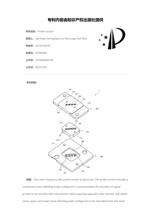
专利名称:Probe socket发明人:Jae-hwan Jeong,Geun-su Kim,Jung-chul Shin申请号:US15916479申请日:20180309公开号:US10884047B2公开日:20210105专利内容由知识产权出版社提供专利附图:摘要:The radio frequency (RF) probe socket is disclosed. The probe socket includes a conductive noise shielding body configured to accommodate the plurality of signalprobes to be parallel with one another while exposing opposite ends thereof, and shield noise; upper and lower noise shielding walls configured to be extended from the noiseshielding body to some areas between the exposed opposite ends of the plurality of signal probes; and upper and lower holding members configured to be arranged on top and bottom sides of the noise shielding body, support the exposed opposite ends of the plurality of signal probes, and comprise accommodating grooves accommodate the noise shielding walls, respectively. With this, the noise shielding wall extended from the shielding block makes a shield between the signal probe pins passing through the upper and lower holding member, thereby preventing crosstalk between the signal probe pins.申请人:LEENO INDUSTRIAL INC.地址:Busan KR国籍:KR代理机构:Park & Associates IP Law, P.C.更多信息请下载全文后查看。
Dixon Bayco API兼容5线光电pires监控系统安装说明说明书

Mounting InstructionsMonitorFloTech model FT103 API Compatible Onboard Monitor is typically mounted on the tank main frame rail, fitting storage box, or any flat surface in easy viewing area near the bottom loading connections. Use the monitor housing as a template to transfer, with a black marker, the four mounting holes to the mounting surface. Drill the holes through and mount the monitor using four 3/8 nuts and bolts. See Diagram F1.To protect the electronics, keep the monitor lid on the enclosure until you are ready to wire the monitor.SensorsFloTech model FT100 can be mounted in a 2”NPT female pipe coupling or through a 2 3/8” hole. When mounting in a 2 3/8” hole the gasket and lock nut provided are used to retain the probe holder in the tank shell or manhole. After the sensor is mounted remove the cap.Loosen the probe clamp screw and adjust the probe to the correct level point. This is typically 3% of compartment volume. It is not recommended cutting the standard 7” sensor to a shorter length. This will cause insufficient time to stop the flow of product within the load racks reaction time.The actual sensing point adjustment should be determined by the total response time required to prevent a tank overfill condition. The FloTech sensor reaction time is one half second. The loading rack will also have a reaction time.Once the probe is adjusted to the proper height, tighten the clamp screw.2 Rev: May 2003 5 WIRE OPTICSensor Wiring It is highly recommended to use FloTech FT400 jacketed 5-conductor cable when wiring a new system. FloTech cable is designed to be oil, UV, and abrasion resistant. We incorporate a noble tin plated stranded copper wire which resist corrosion. These features will provide years of reliable service. After all sensors are mounted in each compartment, align the conduit openings so they face the roll over rail. Thread in cable glands and pull a length of cable through the conduit openings between each sensor. Cut to length leaving approximately 8 inches extra length exiting the top of each probe holder. All sensor wires must enter or leave the probe holder through one of the 1/2NPT openings. Use FloTech FT402 ½ NPT cable glands to ensure a water tight seal. Unused conduit openings must have a ½ NPT pipe plug installed. Use pipe dope on all ½ NPT threads to ensure a water tight seal. Wire the sensor according to Diagram F2 below. Double check your wiring connection when complete. NOTE: It is highly recommended to use a small amount of Silicone RTV sealant in each crimp connection. Fill the FloTech butt end crimps with Silicone RTV sealant prior to inserting the wires then crimp. This will provide a watertight and vibration resistant connection. When wiring is complete, replace each sensor cap and O-ring. Do not pinch a sensor wire when installing the cap.5 WIRE OPTICRev: May 2003 3Monitor WiringTurn off or disconnect power to the trailer before wiring the monitor.Only use the conduit opening marked “POWER INPUT” on diagram F1 to wire 12VDC power to the monitor.After the monitor is bolted to the tank, remove the lid and pull cables from the sensors, sockets, and power into the enclosure. A ¼ amp fast blow fuse must be wiring in series with the 12VDC power input to TB1. Check that the positive 12vdc supply wire is connected to TB1 terminal marker HOT. This is the lower screw on TB1. Be careful that no stray wires are touching the metal barrier or ground terminal. NOTE: This FloTech Onboard Monitor will not work on POSTIVE GROUND electrical systems. Any attempt to wire the monitor to a positive ground system will damage the monitor.4 Rev: May 20035 WIRE OPTICAdditional NotesA. Electrical Apparatus connected to the Onboard Monitor should not use or generate more than 250 volts.B. Installation should be in accordance with NEC ANSI/NFPA 70 and ANSI/ISA RP12.6. In Canada the system should be installed in accordance with the Canadian Electrical Code.C. Maximum ambient temperature is 60°C / 140°F.D. Maximum cable capacitance of 10.1uF and inductance of 4.7mH must not be exceeded.E. Onboard monitor covered under this control diagram are FT103.F. Model FT103 Non –Incendive field wiring parameters (FMRC Only) for TB3 terminals BRN/BRN/BLK, ORN/RED/BLK, andRED/ORN/YEL/BLK are:Vmax. = 30VImax. = 250mAVmax. > Voc or Vt Ci=0UfImax > Isc or It Li=0mHCa>Ci+Ccable La>Li+LcableG. FloTech devices connected to TB2 is sensor FT101 and special length versions of same models with s suffix.Socket Mounting and WiringRemove the socket faceplate and set aside. The bag of hardware is needed to re-assemble the socket. Using the socket hole pattern mark drilling locations on the tank where sockets are to be mounted. Mount the sockets using 3/8" nut and bolts. Install black cable glands FloTech model FT402. Pull a length of FloTech cable FT400 from each socket to the corresponding monitor conduit opening. See Diagram F1. Socket wiring Diagram F3 show how to wire all available FloTech socket. Only follow the wiring instruction needed for the type of socket selected on your tank. Follow the wiring color code as this will make troubleshooting an easier task.Pipe plugs are required for all unused conduit openings in the monitor, sensor, and socket housings.5 WIRE OPTIC Rev: May 2003 5Control IndicatorsSix red LED indicators show when a sensor is wetted or failed. Each red LED is mark 6-1 for each of six possible compartments.Place one of the BLACK LED covers over the red LED compartments not used on your tank installation. EXAMPLE: If this installation is for a 4 compartment tank trailer then LEDs matching compartments 5 and 6 should be covered with a BLACK cover.The yellow LED shows when 12VDC power is connected to the monitor. The green LED indicated when all sensors are dry and the system is permissive.Dixon Bayco WarrantyFor complete warranty information, please refer to the latestDixon catalog.6 Rev: May 2003 5 WIRE OPTIC。
基于端口复用技术的木马研究

基于端⼝复⽤技术的⽊马研究—165—基于端⼝复⽤技术的⽊马研究罗改龙1,程胜利2(1. 江西蓝天学院计算机系,南昌 330098;2. 武汉理⼯⼤学计算机学院,武汉 430000)摘要:隐藏技术是⽊马的关键技术之⼀,其直接决定⽊马的⽣存能⼒。
针对⽬前⽊马在隐藏技术⽅⾯的普遍缺陷,提出了端⼝复⽤的概念,并在实验室研制出了⼀个具有⽆进程和端⼝复⽤特征的⽊马。
该⽊马通过利⽤Windows 的WinSock 2的新特性服务提供者技术,在操作系统中插⼊了⼀个分层式服务提供者,每当⽹络应⽤程序进⾏WinSock 2的调⽤时,⽊马将能获得系统控制权,并通过⼀个系统已经打开的合法端⼝与外界进⾏⽹络通信。
由于该⽊马不需要打开⼀个新的端⼝,因此具有更强的隐藏性。
关键词:⽊马;端⼝复⽤;服务提供者Research on Trojan Horse Based on Port Reuse TechnologyLUO Gai-long 1, CHENG Sheng-li 2(1. Computer Department, Jiangxi Bluesky University, Nanchang 330098; 2. Computer Department, Wuhan University of Technology, Wuhan 430000)【Abstract 】Concealment technology is critical to a Trojan Horse, which decides the survivability ability of the Trojan Horse. The concept of port reuse is brought forward for the common disfigurement of the Trojan Horse in concealment technology. And a Trojan Horse without process or port reuse is made in the lab. The Trojan Horse can insert a layered service provider in operating system by making use of new characteristics of WinSock 2 of Windows, thus it will get the control of the operating system and communicate with outside in an open legal port when network application program makes a call of WinSock 2. For the Trojan Horse which does not have to open a new port in comparison with traditional ones, its concealment ability is stronger.【Key words 】Trojan Horse; port reuse; service provider计算机⼯程Computer Engineering 第33卷第15期Vol.33 No.15 2007年8⽉August 2007·安全技术·⽂章编号:1000—3428(2007)15—0165—02⽂献标识码:A中图分类号:TP3931 概述⽊马是驻留在⽬标机器上的程序,该程序主要在⽬标机器上执⾏⼀些未经授权的操作,如窃取⼝令、银⾏帐号和密码以及控制⽬标计算机等,因此,⽊马程序普遍具有⾮法性。
uprobe_register 原理

uprobe_register 原理uprobe_register 是一个Linux 内核中的函数,用于注册一个uprobe(用户态探针)。
uprobe 是一种动态修改程序执行的机制,可以在程序运行时插入一段额外的代码,用于监控、调试或修改程序行为。
uprobe_register 函数的原理是在内核中创建一个 uprobe 结构体,并将其插入到内核的 uprobe 列表中。
当被监控的程序执行到被注册的函数时,内核会将控制权转交给注册的 uprobe,执行其中的代码,并在执行结束后将控制权还给程序。
uprobe_register 函数的使用需要提供以下参数:1. 被监控的函数地址:uprobe_register 需要知道被监控函数的地址,以便在程序执行到该函数时触发 uprobe。
2. uprobe 结构体:用于描述 uprobe 的行为。
这个结构体包含了一些回调函数,用于定义 uprobe 执行的代码逻辑。
当程序执行到被监控的函数时,内核会根据被监控函数的地址在uprobe 列表中查找是否有对应的 uprobe。
如果找到了匹配的uprobe,内核会执行该 uprobe 中定义的代码逻辑,并将控制权还给程序继续执行。
uprobe_register 函数的调用流程如下:1. 创建一个 uprobe 结构体,并将其初始化。
2. 将被监控函数的地址和uprobe 结构体作为参数,调用uprobe_register 函数。
3. uprobe_register 函数将 uprobe 结构体插入到内核的 uprobe 列表中。
4. 当程序执行到被监控的函数时,内核会触发相应的 uprobe,并执行其中的代码逻辑。
uprobe_register 函数的原理是基于内核中的 ftrace 框架,它通过在被监控函数的入口处插入一段跳转指令,将程序的执行流程转交给 uprobe。
uprobe_register 函数利用了内核中的动态修改指令的机制,实现了对程序行为的监控和修改。
电脑主板各部件图解
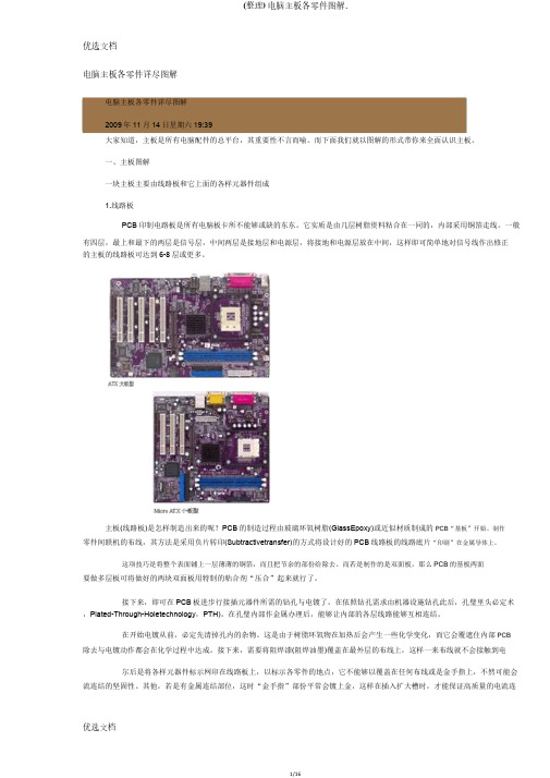
电脑主板各零件详尽图解电脑主板各零件详尽图解2009年11月14日星期六19:39大家知道,主板是所有电脑配件的总平台,其重要性不言而喻。
而下面我们就以图解的形式带你来全面认识主板。
一、主板图解一块主板主要由线路板和它上面的各样元器件组成1.线路板PCB印制电路板是所有电脑板卡所不能够或缺的东东。
它实质是由几层树脂资料粘合在一同的,内部采用铜箔走线。
一般有四层,最上和最下的两层是信号层,中间两层是接地层和电源层,将接地和电源层放在中间,这样即可简单地对信号线作出修正的主板的线路板可达到6-8层或更多。
主板(线路板)是怎样制造出来的呢?PCB的制造过程由玻璃环氧树脂(GlassEpoxy)或近似材质制成的PCB“基板”开始。
制作零件间联机的布线,其方法是采用负片转印(Subtractivetransfer)的方式将设计好的PCB线路板的线路底片“印刷”在金属导体上。
这项技巧是将整个表面铺上一层薄薄的铜箔,而且把节余的部份给除去。
而若是制作的是双面板,那么PCB的基板两面要做多层板可将做好的两块双面板用特制的粘合剂“压合”起来就行了。
接下来,即可在PCB板进步行接插元器件所需的钻孔与电镀了。
在依照钻孔需求由机器设施钻孔此后,孔璧里头必定术,Plated-Through-Holetechnology,PTH)。
在孔璧内部作金属办理后,能够让内部的各层线路能够互相连结。
在开始电镀从前,必定先清掉孔内的杂物。
这是由于树脂环氧物在加热后会产生一些化学变化,而它会覆遮住内部PCB除去与电镀动作都会在化学过程中达成。
接下来,需要将阻焊漆(阻焊油墨)覆盖在最外层的布线上,这样一来布线就不会接触到电尔后是将各样元器件标示网印在线路板上,以标示各零件的地点,它不能够以覆盖在任何布线或是金手指上,不然可能会流连结的坚固性。
其他,若是有金属连结部位,这时“金手指”部份平常会镀上金,这样在插入扩大槽时,才能保证高质量的电流连最后,就是测试了。
