isTurningRadioOffOnS1FailureEnabled未打开导致基站脱管后周围站出现大量切换失败
电脑启动应急按提示处理及解决办法
故障提示:Cache Memory Bad,Do Not enable Cache解决方法:主板高速缓存损坏导致,找售后解决故障提示:Keyboard Not Found解决方法:可能是键盘没有插牢所致,或者主板上的USB、PS2接口损坏导致,可以将键盘插牢或更换接口故障提示:Bad of Missing Command解决方法:损坏或者丢失,使用U盘到正常电脑拷贝一个然后复制到本机引导分区故障提示:开机主机不停地响,系统反复重启解决方法:一般是显卡或内存没有插牢所致,关闭电源后,打开机箱将其插牢故障提示:Disk I/O Error,Replace Disk and Enter解决方法:系统的启动文件丢失,根据提示的丢失文件,从正常的电脑拷贝一个,进入PE 系统,然后复制该文件到引导分区故障提示:CMOS Batter State Low解决方法:CMOS电池已经没电,更换电池即可故障提示:CMOS Checksum Errordefaults loaded解决方法:也有可能是电池没有电所致,但是更换后还出现这个问题,有可能是CMOS数据错误或主板电容问题,找售后故障提示:CMOS Time&Date Not Set解决方法:开机时按住DEL进入BIOS然后设置时间和日期故障提示:Boot.ini非法解决方法:Boot.ini文件中的代码被更改,可以将下面的代码保存到c:\boot.ini中[boot loader]timeout=10default=multi(0)disk(0)rdisk(0)partition(1)\WINDOWS[operating systems]multi(0)disk(0)rdisk(0)partition(1)\WINDOWS="Microsoft Windows XP Professional" /NOEXECUTE=OPTIN /FASTDETECT故障提示:找不到hal.dll解决方法:如果重新编辑过boot.ini仍然无效的话,可以从正常的电脑拷贝该文件,如果内存条损坏,也会出现该问题故障提示:Check Your System On C ,The Type of the File System is Fat32解决方法:有的时候是非正常的关机或重启导致的,一般下次正常操作就不会出现该问题。
CISCO 端口出现err-disabled 现象解决案例
CISCO 端口出现err-disabled 现象解决案例Cisco能智能判定端口故障,为了防止故障商品重量发包,并断开故障端口,这里交换机会为该端口打开err-disabled标签。
一,显示err-disabled 分类。
C3560-48-wx23#show errdisable recoveryErrDisable Reason Timer Status----------------- --------------udld Disabledbpduguard Disabledsecurity-violatio Disabledchannel-misconfig Disabledvmps Disabledpagp-flap Disableddtp-flap Disabledlink-flap Enabledl2ptguard Disabledpsecure-violation Disabledgbic-invalid Disableddhcp-rate-limit Disabledunicast-flood Disabledstorm-control Disabledarp-inspection Disabledloopback DisabledTimer interval: 300 seconds上面显示交换机会出那种类的err-disabled标签。
Disabled 表示不自己重端口, Enabled表示会自动重启端口, Timer interval表示打上err-disabled之后,多少称再重启故障端口。
二,显示交换机发生err-disabled的具体原因C3560-48-wx23#show interface status err-disablePort Name Status Re asonFa0/4 err-disabledlink-flap三,修改自动恢复(重启)端口条件C3560-48-wx23#conf terC3560-48-wx23(config)#errdisable recovery cause link-flap这上就是允许因为“link-flap”导致 err-disabled 端口自动恢复。
dell服务器系统提示错误解决的若干办法

原因
纠正措施
Alert! iDRAC6 not responding.Rebooting.
iDRAC6 未响应 BIOS 通信,一种原因是它未正常运行,另一种原因是它未完成初始化。系统将重新引导。
请等待系统重新引导。
Alert! iDRAC6 not responding.Power required may exceed PSU wattage.
不同级别的内存模块存在于无效的配置中。
请确保内存模块安装在有效的配置中。请参阅内存模块一般安装原则。
DIMM population violation: DIMM <x> Lockstep Pair DIMM <x&y> disabled. Please ensure each lockstep pair is installed correctly.
更换或重置内存模块。请参阅卸下内存模块和安装内存模块。
确保内存模块连接器干净并且在有效配置中安装支持的内存模块。请参阅内存模块一般安装原则。
DIMMs <x> disabled - MemBIST timeout
DIMMs <x> disabled - Rank not found
DIMMs <x> disabled - DIMM communication error
Keyboard stuck key failure
键盘电缆连接器连接不正确,或键盘出现故障。
请重置键盘电缆。如果问题仍然存在,请参阅USB 设备故障排除。
Keyboard fuse has failed
检测到键盘连接器电流过载。
请参阅获得帮助。
Local keyboard may not work because all user accessible USB ports are disabled. If operating locally, power cycle the system and enter system setup program to change settings.
交换机端口状态出现err-disabled的情况分析及解决方法
Cisco交换机端口出现“err-disabled”状态的情况分析1、引言通常情况下,如果交换机运转正常,其中端口一项显示为启用(enable)状态.但是如果交换机的软件(CISCO IOS/CatOS)检测到端口的一些错误,端口将随即被关闭.也就是说,当交换机的操作系统检测到交换机端口发生些错误事件的时候,交换机将自动关闭该端口.2、现象描述当端口处于err-disabled状态,将没有任何流量从该端口被转发出去,也将不接收任何进站流量.从交换机外观上看去,端口相对应的LED 状态灯也将由正常的绿色变为暗黄色(或者叫做橘黄色,官方给的说法是amber,琥珀色).同时使用查看端口状态的一些命令,比如show interfaces,也会看到端口是处于err-disabled状态的.还有种情况是,当交换机因一种错误因素导致端口被禁用(err- disabled),这种情况通常会看到类似如下日志信息:%SPANTREE-SP-2-BLOCK_BPDUGUARD:Received BPDU on port GigabitEthernet0/1 with BPDU Guard enabled. Disabling port. %PM-SP-4-ERR_DISABLE:bpduguard error detected on Gi0/1, putting Gi0/1 in err-disable stateerr-disabled的两个作用的:1.告诉管理员端口状态出错.2.消除因某个端口的错误导致所有端口,或者整个模块功能的出错.err-disabled状态的起因:该特性最初是用于处理特定的冲突形势,比如过分冲突(excessive collisison)和后期冲突(late collision).由于CSMA/CD机制的制定,当发生16次冲突后帧将被丢弃,此时发生excessive collision;而late collision是指在发送方发送了64个字节之后,正常的和合法的冲突就不可能发生了.理论上正常的网络传播一定会在此之前就完成了,但是如果线路过长的话会在前64个字节完成后发生冲突,后期冲突和发生在前64个字节的冲突最明显的区别是后者网卡会自动重新传输正常的冲突帧,但不会重传后期冲突的帧.后期冲突发生在时间超时和中继器的远端.一般而言,这样的冲突在本地网段会简单地判断为一个帧校验序列(FCS)错误.引起这种错误的可能原因有:1.线缆的不规范使用,比如超出了最大传输距离或者使用了错误的线缆类型.2.网卡的不正常工作(物理损坏或者驱动程序的错误).3.端口双工模式的错误配置,如双工不匹配.如下是端口处于err-disabled状态的几种原因:1.双工不匹配.2.端口信道的错误配置.3.违反BPDU守护(BPDU Guard)特性.4.单向链路检测(UDLD).5.检测到后期冲突.6.链路振荡.7.违反某些安全策略.8.端口聚合协议(PAgP)的振荡.9.层2隧道协议(L2TP)守护(L2TP Guard).侦听限速.3、处理过程可以使用show interfaces命令查看端口状态,如:switch#show interfaces gigabitethernet 0/1 statusPortNameStatus Vlan DuplexSpeed TypeGi0/1err-disabled 100 full 1000 1000BaseSX当交换机的某个端口处于err-disabled状态后,交换机将发送为什么这么做的日志信息到控制台端口.也可以使用show log查看系统日志,如: %SPANTREE-SP-2-BLOCK_BPDUGUARD:Received BPDU on port gigabitethernet 0/1 with BPDU Guard enabled. Disabling port.%PM-SP-4-ERR_DISABLE:bpduguard error detected on Gi 0/1, putting Gi0/1 in err-disable state%SPANTREE-2-CHNMISCFG: STP loop - channel 11/1-2 is disabled in vlan 1可以使用show interfaces status err-disabled命令查看处于err-disabled 状态的原因,如:switch #show interfaces status err-disabledPort Name Status Reason Err-disabled VlansFa0/1 err-disabled loopback当出现err-disabled状态后,首先要做的,是找出引起该状态的根源,然后重新启用该端口;如果顺序不一致,将导致该端口再次进入err-disabled状态.4、原因分析以比较常见的做为例子:1).以太网信道(EC)的错误配置:如果要让EC能够正常工作,参与到EC绑定的端口的配置,必须是一致的,比如处于同一VLAN,trunk模式相同,速率和双工模式都匹配等等.如果一端配置了EC,而另一端没有配置EC,STP将关闭配置了EC一方的参与到EC中的端口.并且当PAgP的模式是处于on模式的时候,交换机是不会向外发送PAgP信息去进行协商的(它认为对方是处于EC).这种情况下STP判定出现环路问题,因此将端口设置为err-disabled状态.如:%SPANTREE-2-CHNL_MISCFG: Detected loop due to etherchannel misconfigurationof Gi0/1如下,查看EC信息显示使用的信道组数量为0:SWITCH#show etherchannel summaryFlags: D - down P - in port-channelI - stand-alone s - suspendedH - Hot-standby (LACP only)R - Layer3 S - Layer2U - in use f - failed to allocate aggregatoru - unsuitable for bundlingNumber of channel-groups in use: 0Number of aggregators: 0EC没有正常工作是由于端口被设置为err-disabled状态:SWITCH#show interfaces gigabitethernet 0/1 statusPort Name Status Vlan Duplex Speed TypeGi0/1 err-disabled 100 full 1000 1000BaseSX为找出为何EC没有正常工作,根据错误信息暗示,STP检测到环路.之前提到过,这种情况的发生,是由于一方配置了EC,设置PAgP模式为on 模式,这种模式和desirable模式正好相反,而另一方没有配置EC.因此,为了解决这种问题的发生,将EC的PAgP模式设置为可以主动协商的desirable模式.,然后再重新启用该端口.如下:!interface gigabitethernet 0/1channel-group 1 mode desirable non-silent!2).双工模式不匹配:双工模式不匹配的问题比较常见,由于速率和双工模式自动协商的故障,常导致这种问题的发生.可以使用show interfaces命令查看双方端口的速率和双工模式.后期版本的CDP也能够在将端口处于err-disabled状态之前发出警告日志信息.另外, 网卡的不正常设置也将引起双工模式的不匹配.解决办法,如双方不能自动协商,使用duplex 命令(CISCO IOS和CatOS有所不同)修改双方双工模式使之一致.3).BPDU Guard:通常启用了快速端口(PortFast)特性的端口用于直接连接端工作站这种不会产生BPDU的末端设备.由于PortFast特性假定交换机的端口不会产生物理环路,因此,当在启用了PortFast和BPDU Guard特性的端口上收到BPDU后,该端口将进入err-disabled状态,用于避免潜在环路. 假如我们将两台6509交换机相连,在其中一台上启用PortFast特性并打开BPDU Guard特性:interface gigabitethernet 0/1spanning-tree bpduguard enablespanning-tree portfast enable此时将看到如下日志信息:%PM-SP-4-ERR_DISABLE: bpduguard error detected on Gi0/1, putting Gi0/1 inerr-disable state.验证:SWITCH#show interfaces gigabitethernet 0/1 statusPort NameStatus Vlan Duplex SpeedTypeGi0/1err-disabled 100full BaseSX像这种情况,不能启用PortFast特性,因此禁用该特性可以解决该问题.4).UDLD:UDLD 协议允许通过光纤或铜线相连的设备监控线缆的物理配置,并且可以检测是否存在单向链路.如果检测到有单向链路,UDLD将关闭相关端口并发出警告日志信息.单向链路可以引起一系列的问题,最常见的就是STP拓扑环路.注意,为了启用UDLD,双方必须都支持该协议,并且要单独在每个端口启用UDLD.如果你只在一方启用了UDLD,同样的会引起端口进入err-disabled状态,如:%PM-SP-4-ERR_DISABLE: udld error detected on Gi0/1, putting Gi0/1 inerr-disable state.5).链路振荡错误:链路振荡(flap)是指短时间内端口不停的处于up/down状态,如果端口在10秒内连续振荡5次,端口将被设置为err-disabled状态,如:%PM-4-ERR_DISABLE: link-flap error detected on Gi0/1, putting Gi0/1 inerr-disable state可以使用如下命令查看不同的振荡的值:SWITCH#show errdisable flap-valuesErrDisable Reason Flaps Time (sec)pagp-flap3 30dtp-flap3 30link-flap5 10引起链路震荡的常见因素,可能是物理层的问题,比如GBIC的硬件故障等等.因此解决这种问题通常先从物理层入手.6).回环(loopback)错误:当keepalive信息从交换机的出站端口被发送出去后,又从该接口收到该信息,就会发生回环错误.交换机默认情况下会从所有端口向外发送keepalive信息.但由于STP没能阻塞某些端口,导致这些信息可能会被转发回去形成逻辑环路.因此出现这种情况后,端口将进入err- disabled状态,如:%PM-4-ERR_DISABLE: loopback error detected on Gi0/1, putting Gi0/1 inerr-disable state从CISCO IOS 之后的版本,keepalive信息将不再从光纤和上行端口发送出去,因此解决这种问题的方案是升级CISCO IOS软件版本到或后续版本。
黑莓手机错误代码详解blackberry系统错误提示

黑莓手机错误代码详解blackberry系统错误提示黑莓手机错误代码详解 blackberry系统错误提示希望国内的黑莓用户对黑莓手机出错提示有个很好的认识,从而来解决问题。
101 Previous startup failed当jvm启动过程中,前一个启动的项目失败了,设备已经被重置。
这个错误表明jvm在启动时找到“启动进行中”这个标志位已经设置了,当前屏幕信息为:有意停止“系统继续重置”这个死循环,来纠正系统当前不正确的启动操作102 Invalid code in filesystem在文件系统中发现无效的代码。
手持设备的系统检查.cod文件的变动时,在一些.cod文件中检测到这个问题。
他肯可能是表明生成过程中发生了错误,即在cod文件中存在一个有问题的签名。
如果一些用户操作设备导致这个问题的发生,文件系统的代码被破坏,复位的周期将是连续循环的。
唯一的恢复方法是擦去设备并且恢复一个新的系统。
103 Cannot find starting address找不到启动的地址,用于启动系统的引导cod文件找不到。
这个错误表明一个用于引导系统的cod文件没有安装到设备上,或者格式不正确。
104 Uncaught:非预期:《java模块名》jvm诊断出一个非预期的java代码异常错误抛出,程序可以继续执行,或者手持设备可以用桌面管理器连是USB线安装一个程序调试器来查看这些错误信息。
事件日志里应该包含了异常错误的信息105 Example, DbRecSize( %d ) -> %d举例,DbRecSize( %d ) ->%d文件系统API已经为一种特定的操作返回一种错误状态码,他可能表明在jvm 上存在一个无效的或者错误的文件系统106 Graphics system error图形系统错误,在设备的图形系统里一个错误发生并被检测到107 operator new() called在jvm里,操作new()回调一个c++类,该函数代码没有被正确的从VMRamObject对象来继承,新操作符需要被正确的继承。
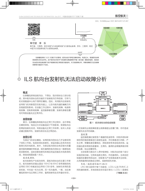
ILS航向台发射机无法启动故障分析
排故过程
设备硬件排查 首先考虑是否电源系统的问题,用万用表检测机柜下面 的可对电池充电的电源系统(BCPS)的三块电池,发现 AC/ DC 转换器的输出电压均为 54V,说明电源系统良好。再次 尝试对两部发射机进行开机, 均无法开启, 且现象一致, 考虑主、 备用发射机同时发生故障,并且故障现象相同的可能性不大, 所以两部发射机的硬件同时故障排除。对机柜面板各个按键进 行操作,均可操作,说明主控制单元以及本地控制及状态显示 单元(LCSU)良好。由此,可以判断航向台机柜硬件基本没 有问题,那么故障会不会是出现在软件上呢?
10 万~ 30 万◎
心不会去考虑获取此类政府资源。而依托单位为企业性质的 技术创新中心的依托单位主管领导往往没有意识到其职责范 围内有协助依托单位获取政府资源的内容,仅仅关注研发活 动,参加相关政府组织的政策培训的人员往往不是技术创新 中心的人员,导致企业不能及时掌握和有效理解科技优惠政 策,技术创新中心也难以发挥自身的优势和作用。部分技术 创新中心还没有形成主动了解政策、获取资源、借力发展自 我的意识。
监控器
监控器是通过接受各个通道的检波信号,对航向信标射 频信号的每项参数进行连续性监视,并对参数进行判断,产 生正常、预警或者告警响应,其检测信号来自检测天线。监 控器也是采用双机配套制,主用机、备用机会根据多数诊断 的结果,给出告警信号。 主控制单元相当于人得中枢神经,对航向台的各个部分 实施控制功能。它用来选择主用机、开启备用机。当来自控 制器的告警信号到达时,控制单元产生转换或者关台控制, 从而将备用机转换成主用机,或者将双机关掉。
指导的同时,应进一步规范管理和相关工作流程,通过规范管 理与主动服务,促进技术创新中心又快又好的发展。
各相关部门加强检查、监督、评估和交流工作
一次语音流量穿越飞塔Gate不通问题的解决过程

一次语音流量穿越飞塔Gate不通的解决过程V 1.0北京超圣信华科技有限公司2016年4月11日问题:一次语音穿越Gate不通的解决过程版本:V1.0日期:2016年4月11日作者:宋泽春摘要:一次语音穿越Gate不通的解决过程关键字:SIP、SDP、SDF、RTP文档记录文档说明本文档描述了一次语音流量穿越飞塔Gate不通的解决过程的说明。
目录文档记录 (3)文档说明 (3)第1章需求 (5)第2章SIP浅析 (5)第3章拓扑结构 (5)第4章配置部分 (6)4.1配置火墙地址 (6)4.2开启负载均衡功能及VOIP高级特性 (6)4.3配置虚拟服务器 (7)4.4配置真实服务器 (7)4.5监控检查 (8)4.6配置虚拟IP (9)4.7策略配置 (10)第5章分割点 (12)第6章遇到的问题 (12)6.1负载均衡回切慢问题 (12)6.2语音无法建立问题 (14)6.3语音IPPBX无法回切问题 (17)第1章需求内部安装两台IPPBX,外部IP分机呼入,通过Fortiner 200D可实现负载均衡功能。
当主设备故障后,呼叫会切换到备用设备。
需求:默认语音网关访问飞塔VIP流量分发到IPPBX A上当IPPBX A异常,语音网关访问飞塔的VIP的流量分发到IPPBX B上当IPPBX A恢复后,语音网关访问飞塔VIP的流量继续分发到IPPBX A上第2章 SIP浅析简单的说SIP有信令流(5060)和媒体流(两个人的通话)两部分组成,信令流主要用作从语音网关到IPPBX管理系统的注册,媒体流用来传输建立好通道的语音流量。
第3章拓扑结构拓扑结构如下:第4章配置部分欲完成上述需求,飞塔防火墙需要启用负载均衡功能。
即,两个IPPBX管理系统作为两台服务器看待,语音网关作为访问者看待,飞塔防火墙通过其负载均衡模块将两台IPPBX管理系统向语音网关发布。
4.1 配置火墙地址确定当前配置为:WAN口IP为192.168.120.44;LAN口IP为192.168.100.99确定内部IPPBX配置(OM50)IPPBX-A:SIP端口5060,RTP端口10010~10266;配置IP分机220,注册密码123321 IPPBX-B:SIP端口5060,RTP端口11010~11266;配置IP分机220,注册密码123321 NAT_IP:需要配置NAT_IP为192.168.120.44,以保证IPPBX信令携带的IP地址是防火墙的WAN口IP,从而可以建立正确的语音流。
Listen EVERYWHERE 故障排除指南说明书
Listen EVERYWHERE Troubleshooting GuideContentsOverview ------------------------------------------------------------------------------------------------------------------- 1 Unable to Perform a Successful Venue Scan -------------------------------------------------------------------- 1 Front Power LED is Solid ------------------------------------------------------------------------------------------- 2 Front Power LED is Blinking Steadily (1 Blink Per Second) ------------------------------------------------ 4 Front Power LED is Blinking Rapidly (2 Blinks Per Second) ----------------------------------------------- 4 Server is Unable to Connect to Cloud Services ----------------------------------------------------------------- 5 High Latency, Noise, Crackling, or Dropouts in Audio --------------------------------------------------------- 5 No Audio or Partial Audio --------------------------------------------------------------------------------------------- 7Overview:The purpose of this tech note is to provide a troubleshooting guide for the ListenEVERYWHERE (LE) server. Most of the issues outlined are usually encountered when initially installing the LE server or after altering a pre-existing installation of the LE server in asignificant way (i.e., installing into a different location, changing networking or audio equipment, etc.). There may be issues or resolutions that extend beyond this document. If so, please do not hesitate to contact Listen Technical Support using the contact information located at the end of this document.Unable to Perform a Successful Venue Scan:If you are reviewing this section, you are not able to connect to the Listen EVERYWHERE server through the Listen EVERYWHERE app using the Venue Scan option. The user will witness a 30-second countdown timer and/or an error message. To preface, theuser must be physically present in the venue location where ListenEVERYWHERE is installed and must be connected to the samenetwork. The server is not designed to stream over the internet ortraverse networks. The Venue Scan feature also requires theallowance of particular ports and services mentioned later in thissection. If this is not desired or possible in the venue, please consultthe Mobile App Connection Methods tech note for alternativeconnection methods.Note: The first time the app is opened on devices running iOS 14 or higher, you will see the prompt “Listen EVERYWHERE would like to find and connect to devices on your local network. This app will beable to discover and connect to devices on the networks you use”, press “OK”. This can be changed atany time in Settings > Privacy > Local Network on the iOS platform.Front Power LED is SolidThis section will provide solutions in a situation where a Venue Scan will fail while thefront power LED on the LE server is solid.•Enable Multicast UDP / Multicast DNS (mDNS) on the network. This is a common problem on guest networks or networks with high levels of security because thisfeature may be disabled. Multicast DNS (mDNS) is used in the discovery processfor the app and the server to connect via a network scan. This then allowsautomatic connection when the app is opened. To enable mDNS, perform thefollowing:o Add the following services to the allowed list in the Gateway/WAP mDNS settings: Array▪_ExXothermic._tcp▪_AsClient_ExXothermic._tcpo Open Port 5353.o Add the mDNS IP address to theallowed subnets list. 224.0.0.251 isthe most common mDNS IPaddress, but it could be any of the224.0.0.0/24 range.•Whitelist the LE server on the network. Onguest networks and VLANs, it’s possiblethat client isolation is enabled. Clientisolation prevents connected wirelessdevices from communicating with otherdevices on the network (such asiOS/Android devices communicating withthe LE server) and disables mDNS. Inconjunction with enabling mDNS on thenetwork (see previous bullet point), the IPaddress or MAC address must be added tothe allowed address list (Whitelist) for the GuestNetwork/VLAN in the Router and/or WAP configuration.•Expand the allocation of IP addresses. The network may be limited by the number of host devices that can acquire an IP address (i.e., connect to thenetwork). This will be evident when the LE server is successfully connected to the network but only some users cannot successfully connect to the network and therefore, are unable to successfully perform a Venue Scan in the LE app. In that case, the subnet mask may need to be expanded to include more hosts. A calculator can be found here. For networks with a single Listen EVERYWHERE server, it is recommended to set the subnet mask to at least 255.255.252.0/22 to accommodate the 1000 user specification of the server. This may vary based on the network infrastructure needs. Class B (default subnet mask of255.255.0.0) is best for medium to large venues.•Consider IP address lease time. Lease time refers to how long a device will reserve an IP address on a network before it is renewed and re-added to the IP address pool availability. Similar to expanding the IP address allocation, the IP address lease time may also be adjusted based on the needs of the venue. It’s recommended to place a Listen EVERYWHERE server on a network with a 24-hour lease time so that devices do not encounter any disruption whilestreaming audio through the Listen EVERYWHERE app. However, a venue may want to consider lowering the lease time in high traffic environments or forapplications that required a user to be connected for a predetermined finite amount of time (e.g., a guided tour).•Ensure that users are connected to the correct network and are not using mobile data. As mentioned previously, make sure that users are connected to the same network as the LE server. To help verify, it may be beneficial toperform a network scan from a mobile device using a network analyzer app.Usually, the LE server should appear with the Server ID (e.g., AEL6-XXXX-XXXX-XXX) as the name and “WIBRAIN” as the manufacturer. If using the LE server on a network without internet connection, some devices may have troubleconnecting. Below are a few tips to help connect to these networks: o When first connecting to the network, you may see a prompt to stay connected even if the network does not have internet. Select Yes orKeep Trying Wi-Fi. Do not manually switch to mobile or cellular data.o Forget the network and reconnect. This may elicit a prompt to stay connected even if the network does not have internet. Select Yes orKeep Trying Wi-Fi. Do not manually switch to mobile or cellular data.o Turn off Mobile / Cellular Data and connect to the network.o Turn on Airplane Mode and connect to the network.Front Power LED is Blinking Steadily (1 Blink Per Second)This section will provide solutions in a situation where a Venue Scan will fail while the front power LED on the LE server is blinking once per second.By default, the Listen EVERYWHERE server is designed to acquire an IP address automatically from a DHCP server. This is typically the router. While acquiring the IP address from the network, the user will see the power LED blink once per second for roughly 30 seconds. If the blinking pattern persists beyond that, an IP address isn’t properly being assigned to the server or the internal components are not functioning properly.•Verify that a DHCP server / router is properly setup and installed. Follow the steps provided by the manufacturer of the networking hardware to set up andprepare the network for use. Sometimes, these devices may fail over time.Performing a factory reset on the networking equipment and following thesetup procedures may resolve the issue.•Check the network cable and Ethernet port. The network cable may be faulty, disconnected, or connected into the wrong Ethernet port on the network switch or router. The Ethernet LAN port may also be faulty, disabled, or configuredincorrectly.•Check the Power supply. A faulty or incorrect power supply will cause internal components of the Listen EVERYWHERE server to function incorrectly. The LEserver uses a 5V / 6.0A / 30W power supply.Front Power LED is Blinking Rapidly (2 Blinks Per Second)This section will provide solutions in a situation where a Venue Scan will fail while the front power LED on the LE server is blinking twice per second.•Verify that the network settings placed on the Listen EVERYWHERE server are correct. Network settings can be adjusted on the LE server through the ServerAdmin interface. Some errors, such as IP address conflicts on the network, willoccur after the configuration is saved and the server is rebooted. When errorslike this are encountered, the front panel LED status will flash in panic mode (2blinks per second) indicating the server has an improper network configuration and cannot communicate on the network. When this happens, the server willrevert to a known working DHCP configuration after 5 minutes.Server is Unable to Connect to Cloud Services:•internet access.•Enable ports and services. This will likely be necessary if the network has a high level of security or firewall in place. Cloud Services communicates via HTTP with the LE server through * over port 1025, with updates communicating over port 80.Refer to Figure 1 on Page 2.High Latency, Noise, Crackling, or Dropouts in Audio:If you are reviewing this section, you are able to successfully connect to the Listen EVERYWHERE server through the Listen EVERYWHERE app. However, the latency of the audio stream through the app seems excessively high or the audio stream has excessive noise, crackling, or dropouts. These audio effects may be heard immediately, occasionally, or infrequently. An example can be heard here.The average latency on the Listen EVERYWHERE server is 60ms but can vary by network and device.•Upgrade the networking equipment. Older and/or low-cost networking equipment may result in unreliable and slower packet delivery, especially when many users areconnected to a single network. It is highly recommended to use high-end consumer-grade networking equipment or enterprise-grade networking equipment to improvepacket reliability and speed. More information and recommended networkingequipment can be found in our Wireless Access Point Optimization for ListenEVERYWHERE tech note.• Do not use a mesh network . A mesh network iscomprised of multiple nodes that communicatewith each other to provide wireless access to asingle network. These nodes may also be calledpoints or extenders. You may also think of thesenodes as being wirelessly daisy-chained to oneanother. Mesh networks have a high likelihood ofcausing excessive latency, dropouts, andunwanted noise because it extends the pathwayfrom the user device to the Listen EVERYWHEREserver. Refer to Figure 2 on the right.• Use an open network (no encryption). Usingencryption can lower the number of users thatcan connect to the WAP and add latency to theLE system. TKIP encryption should not be used.• Enable Quality of Service (QoS) for the LE serveron the network . By default, the LE server uses the 0xB8 Type of Service/Differentiated Services(ToS/DS) tag so that audio data can be prioritized over other data traffic on the network. This priority allows the latency and dropouts to be as low and infrequent as possible while travelling over the network. The QoS setting may still need to be enabled on the managed network, especially if there are many other connected devices or there are existing QoS prioritizations on other connected devices.• Ensure that there is adequate Wi-Fi coverage. If latency improves as a user movescloser to the wireless access point or when there are less users connected to thenetwork, the venue may need to consider adding additional wireless access points for adequate coverage and bandwidth allocation. Network speeds can also be tested using third-party apps. Refer to our Wireless Access Point Optimization for ListenEVERYWHERE tech note for more details.• Consider network frequency . Typically, users will receive better performance on the5GHz frequency versus a 2.4GHz frequency. The 2.4GHz frequency can usually beturned off through your network’s admin interface. However, 2.4GHz frequencies will work more efficiently as the user moves further away from the access point. Both may be considered depending on your wireless access point placement.• Check your mobile device. Some third-party, low-cost and/or older mobile devices maynot have high computing power or strong Wi-Fi antennas. Test with multiple mobiledevices to isolate the problem. If the problem exists on one or few devices, it may benecessary to use an alternate mobile device to stream audio.•Set a static channel on the wireless access point(s). Many WAPs can automatically change channels to try and find one with the least interference. This feature can cause audio dropouts each time the channel changes, as often as every 20 seconds. If it does not settle on a channel after 30-60 minutes, it may be best to choose a channelmanually.•Check your Bluetooth device (if applicable). Bluetooth speakers and headphones can potentially cause an additional 200-700ms in latency. The amount of latency can varybetween Bluetooth devices. Utilizing devices with Bluetooth 5.0 or higher and Bluetooth Low Energy (BLE) can help reduce latency. If using a hearing aid or cochlear implantwith Bluetooth technology, try toggling between listening modes to reduce latency.Bluetooth devices are also susceptible to interference from Wi-Fi signals. Try movingcloser to the wireless access point.•Be mindful of cable runs. Cable runs from the audio source to the Listen EVERYWHERE server should be balanced to avoid introducing interference or noise. If an unbalanced cable is used, you can reduce noise by improving cable shielding, avoiding long cableruns (usually over 15ft), and by avoiding objects that can be picked up by the groundwire.•Avoid ground loops. A ground loop is characterized by the introduction of a humming noise in the audio and can occur when multiple devices are interconnected through a shared ground reference. Grounding is needed for both power and audio connections, so it’s important to not allow these ground references to create a loop within the device setup. When it comes to Listen EVERYWHERE, it may occur when the source audio,other audio devices, and LE server are connected to the same ground reference,usually in the form of a shared power strip or electrical outlets with interconnectedground references. In order to combat a ground loop occurrence, the equipment’scircuitry will need to be separated or a ground loop isolator can be installed.No Audio or Partial Audio:If you are reviewing this section, you are able to successfully connect to the Listen EVERYWHERE server through the Listen EVERYWHERE app. However, no audio or partial audio is heard on the channel after channel selection within the app. The LE server contains green LEDs on the front of the unit that will illuminate when audio is present and at an adequate level. This may help determine if the issue is audio-based or network-based and can be troubleshot accordingly.•Correctly connect audio to the Listen EVERYWHERE server. If the server is set up for mono, connect to a single terminal block input, or connect to one vertical pair of redand white RCA connections (LW-100P only). If the server is set up for stereo, connect toa pair of terminal block inputs, or connect to one RCA input on the left and one RCAinput on the right (LW-100P only). The LW-150 Dante connection handles both mono and stereo with the same connection. Refer to Figure 3 below.•Verify that audio cables being used are working properly or have been properly assembled. This can be tested by using a different cable. If a custom-made cable is being used, some wiring diagrams are available on our Audio Input Connection for Listen EVERYWHERE tech note to ensure that it had been made properly. A multimeter may also be used to check for continuity between the two connectors of the cable. •Verify that headphones are working properly. This can be tested by using a different pair of headphones and/or confirming that the audio can be heard through thespeaker of the smartphone or tablet used for streaming.•Audio input should be line level. Mic level audio sources are not meant to be used on the Listen EVERYWHERE server. Doing so may result in low level audio and pitch where no audio or only partial audio may be heard.•Ensure that traffic is enabled on port 16384. The LE Server sends RTP packets via UDP to the app over a range of ports, including dynamic ephemeral ports. The mobile app listens via UDP over port 16384. If these ports are not enabled, no audio will stream through the app. See Figure 1 on Page 2. It also may be necessary to perform anetwork scan or capture (e.g., through Wireshark) to identify which ports the network is utilizing. See example below.•Do not attempt to stream audio across different networks. Attempting to stream across different networks will likely end up producing no audio within the Listen EVERYWHERE app.Should you have any further questions or concerns, please contact Listen Technologies’Technical Services team at 1-800-330-0891 or**********************for assistance.。
Indradrive 系列 故障代码
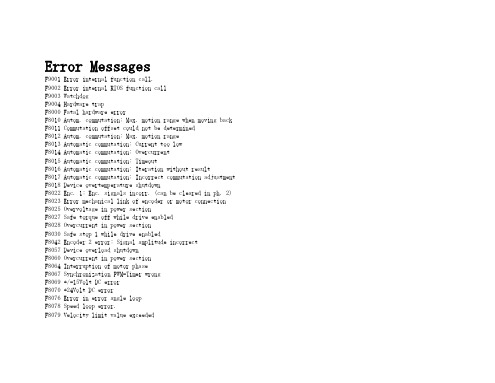
Error MessagesF9001 Error internal function call.F9002 Error internal RTOS function callF9003 WatchdogF9004 Hardware trapF8000 Fatal hardware errorF8010 Autom. commutation: Max. motion range when moving back F8011 Commutation offset could not be determinedF8012 Autom. commutation: Max. motion rangeF8013 Automatic commutation: Current too lowF8014 Automatic commutation: OvercurrentF8015 Automatic commutation: TimeoutF8016 Automatic commutation: Iteration without resultF8017 Automatic commutation: Incorrect commutation adjustment F8018 Device overtemperature shutdownF8022 Enc. 1: Enc. signals incorr. (can be cleared in ph. 2) F8023 Error mechanical link of encoder or motor connectionF8025 Overvoltage in power sectionF8027 Safe torque off while drive enabledF8028 Overcurrent in power sectionF8030 Safe stop 1 while drive enabledF8042 Encoder 2 error: Signal amplitude incorrectF8057 Device overload shutdownF8060 Overcurrent in power sectionF8064 Interruption of motor phaseF8067 Synchronization PWM-Timer wrongF8069 +/-15Volt DC errorF8070 +24Volt DC errorF8076 Error in error angle loopF8078 Speed loop error.F8079 Velocity limit value exceededF8091 Power section defectiveF8100 Error when initializing the parameter handlingF8102 Error when initializing power sectionF8118 Invalid power section/firmware combinationF8120 Invalid control section/firmware combinationF8122 Control section defectiveF8129 Incorrect optional module firmwareF8130 Firmware of option 2 of safety technology defectiveF8133 Error when checking interrupting circuitsF8134 SBS: Fatal errorF8135 SMD: Velocity exceededF8140 Fatal CCD error.F8201 Safety command for basic initialization incorrectF8203 Safety technology configuration parameter invalidF8813 Connection error mains chokeF8830 Power section errorF8838 Overcurrent external braking resistorF7010 Safely-limited increment exceededF7011 Safely-monitored position, exceeded in pos. DirectionF7012 Safely-monitored position, exceeded in neg. DirectionF7013 Safely-limited speed exceededF7020 Safe maximum speed exceededF7021 Safely-limited position exceededF7030 Position window Safe stop 2 exceededF7031 Incorrect direction of motionF7040 Validation error parameterized - effective thresholdF7041 Actual position value validation errorF7042 Validation error of safe operation modeF7043 Error of output stage interlockF7050 Time for stopping process exceeded8.3.15 F7051 Safely-monitored deceleration exceeded (159)8.4 Travel Range Errors (F6xxx) (161)8.4.1 Behavior in the Case of Travel Range Errors (161)8.4.2 F6010 PLC Runtime Error (162)8.4.3 F6024 Maximum braking time exceeded (163)8.4.4 F6028 Position limit value exceeded (overflow) (164)8.4.5 F6029 Positive position limit exceeded (164)8.4.6 F6030 Negative position limit exceeded (165)8.4.7 F6034 Emergency-Stop (166)8.4.8 F6042 Both travel range limit switches activated (167)8.4.9 F6043 Positive travel range limit switch activated (167)8.4.10 F6044 Negative travel range limit switch activated (168)8.4.11 F6140 CCD slave error (emergency halt) (169)8.5 Interface Errors (F4xxx) (169)8.5.1 Behavior in the Case of Interface Errors (169)8.5.2 F4001 Sync telegram failure (170)8.5.3 F4002 RTD telegram failure (171)8.5.4 F4003 Invalid communication phase shutdown (172)8.5.5 F4004 Error during phase progression (172)8.5.6 F4005 Error during phase regression (173)8.5.7 F4006 Phase switching without ready signal (173)8.5.8 F4009 Bus failure (173)8.5.9 F4012 Incorrect I/O length (175)8.5.10 F4016 PLC double real-time channel failure (176)8.5.11 F4017 S-III: Incorrect sequence during phase switch (176)8.5.12 F4034 Emergency-Stop (177)8.5.13 F4140 CCD communication error (178)8.6 Non-Fatal Safety Technology Errors (F3xxx) (178)8.6.1 Behavior in the Case of Non-Fatal Safety Technology Errors (178)8.6.2 F3111 Refer. missing when selecting safety related end pos (179)8.6.3 F3112 Safe reference missing (179)8.6.4 F3115 Brake check time interval exceeded (181)Troubleshooting Guide | Rexroth IndraDrive Electric Drivesand ControlsI Bosch Rexroth AG VII/XXIITable of ContentsPage8.6.5 F3116 Nominal load torque of holding system exceeded (182)8.6.6 F3117 Actual position values validation error (182)8.6.7 F3122 SBS: System error (183)8.6.8 F3123 SBS: Brake check missing (184)8.6.9 F3130 Error when checking input signals (185)8.6.10 F3131 Error when checking acknowledgment signal (185)8.6.11 F3132 Error when checking diagnostic output signal (186)8.6.12 F3133 Error when checking interrupting circuits (187)8.6.13 F3134 Dynamization time interval incorrect (188)8.6.14 F3135 Dynamization pulse width incorrect (189)8.6.15 F3140 Safety parameters validation error (192)8.6.16 F3141 Selection validation error (192)8.6.17 F3142 Activation time of enabling control exceeded (193)8.6.18 F3143 Safety command for clearing errors incorrect (194)8.6.19 F3144 Incorrect safety configuration (195)8.6.20 F3145 Error when unlocking the safety door (196)8.6.21 F3146 System error channel 2 (197)8.6.22 F3147 System error channel 1 (198)8.6.23 F3150 Safety command for system start incorrect (199)8.6.24 F3151 Safety command for system halt incorrect (200)8.6.25 F3152 Incorrect backup of safety technology data (201)8.6.26 F3160 Communication error of safe communication (202)8.7 Non-Fatal Errors (F2xxx) (202)8.7.1 Behavior in the Case of Non-Fatal Errors (202)8.7.2 F2002 Encoder assignment not allowed for synchronization (203)8.7.3 F2003 Motion step skipped (203)8.7.4 F2004 Error in MotionProfile (204)8.7.5 F2005 Cam table invalid (205)8.7.6 F2006 MMC was removed (206)8.7.7 F2007 Switching to non-initialized operation mode (206)8.7.8 F2008 RL The motor type has changed (207)8.7.9 F2009 PL Load parameter default values (208)8.7.10 F2010 Error when initializing digital I/O (-> S-0-0423) (209)8.7.11 F2011 PLC - Error no. 1 (210)8.7.12 F2012 PLC - Error no. 2 (210)8.7.13 F2013 PLC - Error no. 3 (211)8.7.14 F2014 PLC - Error no. 4 (211)8.7.15 F2018 Device overtemperature shutdown (211)8.7.16 F2019 Motor overtemperature shutdown (212)8.7.17 F2021 Motor temperature monitor defective (213)8.7.18 F2022 Device temperature monitor defective (214)8.7.19 F2025 Drive not ready for control (214)8.7.20 F2026 Undervoltage in power section (215)8.7.21 F2027 Excessive oscillation in DC bus (216)8.7.22 F2028 Excessive deviation (216)8.7.23 F2031 Encoder 1 error: Signal amplitude incorrect (217)VIII/XXII Bosch Rexroth AG | Electric Drivesand ControlsRexroth IndraDrive | Troubleshooting GuideTable of ContentsPage8.7.24 F2032 Validation error during commutation fine adjustment (217)8.7.25 F2033 External power supply X10 error (218)8.7.26 F2036 Excessive position feedback difference (219)8.7.27 F2037 Excessive position command difference (220)8.7.28 F2039 Maximum acceleration exceeded (220)8.7.29 F2040 Device overtemperature 2 shutdown (221)8.7.30 F2042 Encoder 2: Encoder signals incorrect (222)8.7.31 F2043 Measuring encoder: Encoder signals incorrect (222)8.7.32 F2044 External power supply X15 error (223)8.7.33 F2048 Low battery voltage (224)8.7.34 F2050 Overflow of target position preset memory (225)8.7.35 F2051 No sequential block in target position preset memory (225)8.7.36 F2053 Incr. encoder emulator: Pulse frequency too high (226)8.7.37 F2054 Incr. encoder emulator: Hardware error (226)8.7.38 F2055 External power supply dig. I/O error (227)8.7.39 F2057 Target position out of travel range (227)8.7.40 F2058 Internal overflow by positioning input (228)8.7.41 F2059 Incorrect command value direction when positioning (229)8.7.42 F2063 Internal overflow master axis generator (230)8.7.43 F2064 Incorrect cmd value direction master axis generator (230)8.7.44 F2067 Synchronization to master communication incorrect (231)8.7.45 F2068 Brake error (231)8.7.46 F2069 Error when releasing the motor holding brake (232)8.7.47 F2074 Actual pos. value 1 outside absolute encoder window (232)8.7.48 F2075 Actual pos. value 2 outside absolute encoder window (233)8.7.49 F2076 Actual pos. value 3 outside absolute encoder window (234)8.7.50 F2077 Current measurement trim wrong (235)8.7.51 F2086 Error supply module (236)8.7.52 F2087 Module group communication error (236)8.7.53 F2100 Incorrect access to command value memory (237)8.7.54 F2101 It was impossible to address MMC (237)8.7.55 F2102 It was impossible to address I2C memory (238)8.7.56 F2103 It was impossible to address EnDat memory (238)8.7.57 F2104 Commutation offset invalid (239)8.7.58 F2105 It was impossible to address Hiperface memory (239)8.7.59 F2110 Error in non-cyclical data communic. of power section (240)8.7.60 F2120 MMC: Defective or missing, replace (240)8.7.61 F2121 MMC: Incorrect data or file, create correctly (241)8.7.62 F2122 MMC: Incorrect IBF file, correct it (241)8.7.63 F2123 Retain data backup impossible (242)8.7.64 F2124 MMC: Saving too slowly, replace (243)8.7.65 F2130 Error comfort control panel (243)8.7.66 F2140 CCD slave error (243)8.7.67 F2150 MLD motion function block error (244)8.7.68 F2174 Loss of motor encoder reference (244)8.7.69 F2175 Loss of optional encoder reference (245)Troubleshooting Guide | Rexroth IndraDrive Electric Drivesand Controls| Bosch Rexroth AG IX/XXIITable of ContentsPage8.7.70 F2176 Loss of measuring encoder reference (246)8.7.71 F2177 Modulo limitation error of motor encoder (246)8.7.72 F2178 Modulo limitation error of optional encoder (247)8.7.73 F2179 Modulo limitation error of measuring encoder (247)8.7.74 F2190 Incorrect Ethernet configuration (248)8.7.75 F2260 Command current limit shutoff (249)8.7.76 F2270 Analog input 1 or 2, wire break (249)8.7.77 F2802 PLL is not synchronized (250)8.7.78 F2814 Undervoltage in mains (250)8.7.79 F2815 Overvoltage in mains (251)8.7.80 F2816 Softstart fault power supply unit (251)8.7.81 F2817 Overvoltage in power section (251)8.7.82 F2818 Phase failure (252)8.7.83 F2819 Mains failure (253)8.7.84 F2820 Braking resistor overload (253)8.7.85 F2821 Error in control of braking resistor (254)8.7.86 F2825 Switch-on threshold braking resistor too low (255)8.7.87 F2833 Ground fault in motor line (255)8.7.88 F2834 Contactor control error (256)8.7.89 F2835 Mains contactor wiring error (256)8.7.90 F2836 DC bus balancing monitor error (257)8.7.91 F2837 Contactor monitoring error (257)8.7.92 F2840 Error supply shutdown (257)8.7.93 F2860 Overcurrent in mains-side power section (258)8.7.94 F2890 Invalid device code (259)8.7.95 F2891 Incorrect interrupt timing (259)8.7.96 F2892 Hardware variant not supported (259)8.8 SERCOS Error Codes / Error Messages of Serial Communication (259)9 Warnings (Exxxx) (263)9.1 Fatal Warnings (E8xxx) (263)9.1.1 Behavior in the Case of Fatal Warnings (263)9.1.2 E8025 Overvoltage in power section (263)9.1.3 E8026 Undervoltage in power section (264)9.1.4 E8027 Safe torque off while drive enabled (265)9.1.5 E8028 Overcurrent in power section (265)9.1.6 E8029 Positive position limit exceeded (266)9.1.7 E8030 Negative position limit exceeded (267)9.1.8 E8034 Emergency-Stop (268)9.1.9 E8040 Torque/force actual value limit active (268)9.1.10 E8041 Current limit active (269)9.1.11 E8042 Both travel range limit switches activated (269)9.1.12 E8043 Positive travel range limit switch activated (270)9.1.13 E8044 Negative travel range limit switch activated (271)9.1.14 E8055 Motor overload, current limit active (271)9.1.15 E8057 Device overload, current limit active (272)X/XXII Bosch Rexroth AG | Electric Drivesand ControlsRexroth IndraDrive | Troubleshooting GuideTable of ContentsPage9.1.16 E8058 Drive system not ready for operation (273)9.1.17 E8260 Torque/force command value limit active (273)9.1.18 E8802 PLL is not synchronized (274)9.1.19 E8814 Undervoltage in mains (275)9.1.20 E8815 Overvoltage in mains (275)9.1.21 E8818 Phase failure (276)9.1.22 E8819 Mains failure (276)9.2 Warnings of Category E4xxx (277)9.2.1 E4001 Double MST failure shutdown (277)9.2.2 E4002 Double MDT failure shutdown (278)9.2.3 E4005 No command value input via master communication (279)9.2.4 E4007 SERCOS III: Consumer connection failed (280)9.2.5 E4008 Invalid addressing command value data container A (280)9.2.6 E4009 Invalid addressing actual value data container A (281)9.2.7 E4010 Slave not scanned or address 0 (281)9.2.8 E4012 Maximum number of CCD slaves exceeded (282)9.2.9 E4013 Incorrect CCD addressing (282)9.2.10 E4014 Incorrect phase switch of CCD slaves (283)9.3 Possible Warnings When Operating Safety Technology (E3xxx) (283)9.3.1 Behavior in Case a Safety Technology Warning Occurs (283)9.3.2 E3100 Error when checking input signals (284)9.3.3 E3101 Error when checking acknowledgment signal (284)9.3.4 E3102 Actual position values validation error (285)9.3.5 E3103 Dynamization failed (285)9.3.6 E3104 Safety parameters validation error (286)9.3.7 E3105 Validation error of safe operation mode (286)9.3.8 E3106 System error safety technology (287)9.3.9 E3107 Safe reference missing (287)9.3.10 E3108 Safely-monitored deceleration exceeded (288)9.3.11 E3110 Time interval of forced dynamization exceeded (289)9.3.12 E3115 Prewarning, end of brake check time interval (289)9.3.13 E3116 Nominal load torque of holding system reached (290)9.4 Non-Fatal Warnings (E2xxx) (290)9.4.1 Behavior in Case a Non-Fatal Warning Occurs (290)9.4.2 E2010 Position control with encoder 2 not possible (291)9.4.3 E2011 PLC - Warning no. 1 (291)9.4.4 E2012 PLC - Warning no. 2 (291)9.4.5 E2013 PLC - Warning no. 3 (292)9.4.6 E2014 PLC - Warning no. 4 (292)9.4.7 E2021 Motor temperature outside of measuring range (292)9.4.8 E2026 Undervoltage in power section (293)9.4.9 E2040 Device overtemperature 2 prewarning (294)9.4.10 E2047 Interpolation velocity = 0 (294)9.4.11 E2048 Interpolation acceleration = 0 (295)9.4.12 E2049 Positioning velocity >= limit value (296)9.4.13 E2050 Device overtemp. Prewarning (297)Troubleshooting Guide | Rexroth IndraDrive Electric Drivesand Controls| Bosch Rexroth AG XI/XXIITable of ContentsPage9.4.14 E2051 Motor overtemp. prewarning (298)9.4.15 E2053 Target position out of travel range (298)9.4.16 E2054 Not homed (300)9.4.17 E2055 Feedrate override S-0-0108 = 0 (300)9.4.18 E2056 Torque limit = 0 (301)9.4.19 E2058 Selected positioning block has not been programmed (302)9.4.20 E2059 Velocity command value limit active (302)9.4.21 E2061 Device overload prewarning (303)9.4.22 E2063 Velocity command value > limit value (304)9.4.23 E2064 Target position out of num. range (304)9.4.24 E2069 Holding brake torque too low (305)9.4.25 E2070 Acceleration limit active (306)9.4.26 E2074 Encoder 1: Encoder signals disturbed (306)9.4.27 E2075 Encoder 2: Encoder signals disturbed (307)9.4.28 E2076 Measuring encoder: Encoder signals disturbed (308)9.4.29 E2077 Absolute encoder monitoring, motor encoder (encoder alarm) (308)9.4.30 E2078 Absolute encoder monitoring, opt. encoder (encoder alarm) (309)9.4.31 E2079 Absolute enc. monitoring, measuring encoder (encoder alarm) (309)9.4.32 E2086 Prewarning supply module overload (310)9.4.33 E2092 Internal synchronization defective (310)9.4.34 E2100 Positioning velocity of master axis generator too high (311)9.4.35 E2101 Acceleration of master axis generator is zero (312)9.4.36 E2140 CCD error at node (312)9.4.37 E2270 Analog input 1 or 2, wire break (312)9.4.38 E2802 HW control of braking resistor (313)9.4.39 E2810 Drive system not ready for operation (314)9.4.40 E2814 Undervoltage in mains (314)9.4.41 E2816 Undervoltage in power section (314)9.4.42 E2818 Phase failure (315)9.4.43 E2819 Mains failure (315)9.4.44 E2820 Braking resistor overload prewarning (316)9.4.45 E2829 Not ready for power on (316)。
3GPP TS 36.331 V13.2.0 (2016-06)

3GPP TS 36.331 V13.2.0 (2016-06)Technical Specification3rd Generation Partnership Project;Technical Specification Group Radio Access Network;Evolved Universal Terrestrial Radio Access (E-UTRA);Radio Resource Control (RRC);Protocol specification(Release 13)The present document has been developed within the 3rd Generation Partnership Project (3GPP TM) and may be further elaborated for the purposes of 3GPP. The present document has not been subject to any approval process by the 3GPP Organizational Partners and shall not be implemented.This Specification is provided for future development work within 3GPP only. The Organizational Partners accept no liability for any use of this Specification. Specifications and reports for implementation of the 3GPP TM system should be obtained via the 3GPP Organizational Partners' Publications Offices.KeywordsUMTS, radio3GPPPostal address3GPP support office address650 Route des Lucioles - Sophia AntipolisValbonne - FRANCETel.: +33 4 92 94 42 00 Fax: +33 4 93 65 47 16InternetCopyright NotificationNo part may be reproduced except as authorized by written permission.The copyright and the foregoing restriction extend to reproduction in all media.© 2016, 3GPP Organizational Partners (ARIB, ATIS, CCSA, ETSI, TSDSI, TTA, TTC).All rights reserved.UMTS™ is a Trade Mark of ETSI registered for the benefit of its members3GPP™ is a Trade Mark of ETSI registered for the benefit of its Members and of the 3GPP Organizational PartnersLTE™ is a Trade Mark of ETSI currently being registered for the benefit of its Members and of the 3GPP Organizational Partners GSM® and the GSM logo are registered and owned by the GSM AssociationBluetooth® is a Trade Mark of the Bluetooth SIG registered for the benefit of its membersContentsForeword (18)1Scope (19)2References (19)3Definitions, symbols and abbreviations (22)3.1Definitions (22)3.2Abbreviations (24)4General (27)4.1Introduction (27)4.2Architecture (28)4.2.1UE states and state transitions including inter RAT (28)4.2.2Signalling radio bearers (29)4.3Services (30)4.3.1Services provided to upper layers (30)4.3.2Services expected from lower layers (30)4.4Functions (30)5Procedures (32)5.1General (32)5.1.1Introduction (32)5.1.2General requirements (32)5.2System information (33)5.2.1Introduction (33)5.2.1.1General (33)5.2.1.2Scheduling (34)5.2.1.2a Scheduling for NB-IoT (34)5.2.1.3System information validity and notification of changes (35)5.2.1.4Indication of ETWS notification (36)5.2.1.5Indication of CMAS notification (37)5.2.1.6Notification of EAB parameters change (37)5.2.1.7Access Barring parameters change in NB-IoT (37)5.2.2System information acquisition (38)5.2.2.1General (38)5.2.2.2Initiation (38)5.2.2.3System information required by the UE (38)5.2.2.4System information acquisition by the UE (39)5.2.2.5Essential system information missing (42)5.2.2.6Actions upon reception of the MasterInformationBlock message (42)5.2.2.7Actions upon reception of the SystemInformationBlockType1 message (42)5.2.2.8Actions upon reception of SystemInformation messages (44)5.2.2.9Actions upon reception of SystemInformationBlockType2 (44)5.2.2.10Actions upon reception of SystemInformationBlockType3 (45)5.2.2.11Actions upon reception of SystemInformationBlockType4 (45)5.2.2.12Actions upon reception of SystemInformationBlockType5 (45)5.2.2.13Actions upon reception of SystemInformationBlockType6 (45)5.2.2.14Actions upon reception of SystemInformationBlockType7 (45)5.2.2.15Actions upon reception of SystemInformationBlockType8 (45)5.2.2.16Actions upon reception of SystemInformationBlockType9 (46)5.2.2.17Actions upon reception of SystemInformationBlockType10 (46)5.2.2.18Actions upon reception of SystemInformationBlockType11 (46)5.2.2.19Actions upon reception of SystemInformationBlockType12 (47)5.2.2.20Actions upon reception of SystemInformationBlockType13 (48)5.2.2.21Actions upon reception of SystemInformationBlockType14 (48)5.2.2.22Actions upon reception of SystemInformationBlockType15 (48)5.2.2.23Actions upon reception of SystemInformationBlockType16 (48)5.2.2.24Actions upon reception of SystemInformationBlockType17 (48)5.2.2.25Actions upon reception of SystemInformationBlockType18 (48)5.2.2.26Actions upon reception of SystemInformationBlockType19 (49)5.2.3Acquisition of an SI message (49)5.2.3a Acquisition of an SI message by BL UE or UE in CE or a NB-IoT UE (50)5.3Connection control (50)5.3.1Introduction (50)5.3.1.1RRC connection control (50)5.3.1.2Security (52)5.3.1.2a RN security (53)5.3.1.3Connected mode mobility (53)5.3.1.4Connection control in NB-IoT (54)5.3.2Paging (55)5.3.2.1General (55)5.3.2.2Initiation (55)5.3.2.3Reception of the Paging message by the UE (55)5.3.3RRC connection establishment (56)5.3.3.1General (56)5.3.3.1a Conditions for establishing RRC Connection for sidelink communication/ discovery (58)5.3.3.2Initiation (59)5.3.3.3Actions related to transmission of RRCConnectionRequest message (63)5.3.3.3a Actions related to transmission of RRCConnectionResumeRequest message (64)5.3.3.4Reception of the RRCConnectionSetup by the UE (64)5.3.3.4a Reception of the RRCConnectionResume by the UE (66)5.3.3.5Cell re-selection while T300, T302, T303, T305, T306, or T308 is running (68)5.3.3.6T300 expiry (68)5.3.3.7T302, T303, T305, T306, or T308 expiry or stop (69)5.3.3.8Reception of the RRCConnectionReject by the UE (70)5.3.3.9Abortion of RRC connection establishment (71)5.3.3.10Handling of SSAC related parameters (71)5.3.3.11Access barring check (72)5.3.3.12EAB check (73)5.3.3.13Access barring check for ACDC (73)5.3.3.14Access Barring check for NB-IoT (74)5.3.4Initial security activation (75)5.3.4.1General (75)5.3.4.2Initiation (76)5.3.4.3Reception of the SecurityModeCommand by the UE (76)5.3.5RRC connection reconfiguration (77)5.3.5.1General (77)5.3.5.2Initiation (77)5.3.5.3Reception of an RRCConnectionReconfiguration not including the mobilityControlInfo by theUE (77)5.3.5.4Reception of an RRCConnectionReconfiguration including the mobilityControlInfo by the UE(handover) (79)5.3.5.5Reconfiguration failure (83)5.3.5.6T304 expiry (handover failure) (83)5.3.5.7Void (84)5.3.5.7a T307 expiry (SCG change failure) (84)5.3.5.8Radio Configuration involving full configuration option (84)5.3.6Counter check (86)5.3.6.1General (86)5.3.6.2Initiation (86)5.3.6.3Reception of the CounterCheck message by the UE (86)5.3.7RRC connection re-establishment (87)5.3.7.1General (87)5.3.7.2Initiation (87)5.3.7.3Actions following cell selection while T311 is running (88)5.3.7.4Actions related to transmission of RRCConnectionReestablishmentRequest message (89)5.3.7.5Reception of the RRCConnectionReestablishment by the UE (89)5.3.7.6T311 expiry (91)5.3.7.7T301 expiry or selected cell no longer suitable (91)5.3.7.8Reception of RRCConnectionReestablishmentReject by the UE (91)5.3.8RRC connection release (92)5.3.8.1General (92)5.3.8.2Initiation (92)5.3.8.3Reception of the RRCConnectionRelease by the UE (92)5.3.8.4T320 expiry (93)5.3.9RRC connection release requested by upper layers (93)5.3.9.1General (93)5.3.9.2Initiation (93)5.3.10Radio resource configuration (93)5.3.10.0General (93)5.3.10.1SRB addition/ modification (94)5.3.10.2DRB release (95)5.3.10.3DRB addition/ modification (95)5.3.10.3a1DC specific DRB addition or reconfiguration (96)5.3.10.3a2LWA specific DRB addition or reconfiguration (98)5.3.10.3a3LWIP specific DRB addition or reconfiguration (98)5.3.10.3a SCell release (99)5.3.10.3b SCell addition/ modification (99)5.3.10.3c PSCell addition or modification (99)5.3.10.4MAC main reconfiguration (99)5.3.10.5Semi-persistent scheduling reconfiguration (100)5.3.10.6Physical channel reconfiguration (100)5.3.10.7Radio Link Failure Timers and Constants reconfiguration (101)5.3.10.8Time domain measurement resource restriction for serving cell (101)5.3.10.9Other configuration (102)5.3.10.10SCG reconfiguration (103)5.3.10.11SCG dedicated resource configuration (104)5.3.10.12Reconfiguration SCG or split DRB by drb-ToAddModList (105)5.3.10.13Neighbour cell information reconfiguration (105)5.3.10.14Void (105)5.3.10.15Sidelink dedicated configuration (105)5.3.10.16T370 expiry (106)5.3.11Radio link failure related actions (107)5.3.11.1Detection of physical layer problems in RRC_CONNECTED (107)5.3.11.2Recovery of physical layer problems (107)5.3.11.3Detection of radio link failure (107)5.3.12UE actions upon leaving RRC_CONNECTED (109)5.3.13UE actions upon PUCCH/ SRS release request (110)5.3.14Proximity indication (110)5.3.14.1General (110)5.3.14.2Initiation (111)5.3.14.3Actions related to transmission of ProximityIndication message (111)5.3.15Void (111)5.4Inter-RAT mobility (111)5.4.1Introduction (111)5.4.2Handover to E-UTRA (112)5.4.2.1General (112)5.4.2.2Initiation (112)5.4.2.3Reception of the RRCConnectionReconfiguration by the UE (112)5.4.2.4Reconfiguration failure (114)5.4.2.5T304 expiry (handover to E-UTRA failure) (114)5.4.3Mobility from E-UTRA (114)5.4.3.1General (114)5.4.3.2Initiation (115)5.4.3.3Reception of the MobilityFromEUTRACommand by the UE (115)5.4.3.4Successful completion of the mobility from E-UTRA (116)5.4.3.5Mobility from E-UTRA failure (117)5.4.4Handover from E-UTRA preparation request (CDMA2000) (117)5.4.4.1General (117)5.4.4.2Initiation (118)5.4.4.3Reception of the HandoverFromEUTRAPreparationRequest by the UE (118)5.4.5UL handover preparation transfer (CDMA2000) (118)5.4.5.1General (118)5.4.5.2Initiation (118)5.4.5.3Actions related to transmission of the ULHandoverPreparationTransfer message (119)5.4.5.4Failure to deliver the ULHandoverPreparationTransfer message (119)5.4.6Inter-RAT cell change order to E-UTRAN (119)5.4.6.1General (119)5.4.6.2Initiation (119)5.4.6.3UE fails to complete an inter-RAT cell change order (119)5.5Measurements (120)5.5.1Introduction (120)5.5.2Measurement configuration (121)5.5.2.1General (121)5.5.2.2Measurement identity removal (122)5.5.2.2a Measurement identity autonomous removal (122)5.5.2.3Measurement identity addition/ modification (123)5.5.2.4Measurement object removal (124)5.5.2.5Measurement object addition/ modification (124)5.5.2.6Reporting configuration removal (126)5.5.2.7Reporting configuration addition/ modification (127)5.5.2.8Quantity configuration (127)5.5.2.9Measurement gap configuration (127)5.5.2.10Discovery signals measurement timing configuration (128)5.5.2.11RSSI measurement timing configuration (128)5.5.3Performing measurements (128)5.5.3.1General (128)5.5.3.2Layer 3 filtering (131)5.5.4Measurement report triggering (131)5.5.4.1General (131)5.5.4.2Event A1 (Serving becomes better than threshold) (135)5.5.4.3Event A2 (Serving becomes worse than threshold) (136)5.5.4.4Event A3 (Neighbour becomes offset better than PCell/ PSCell) (136)5.5.4.5Event A4 (Neighbour becomes better than threshold) (137)5.5.4.6Event A5 (PCell/ PSCell becomes worse than threshold1 and neighbour becomes better thanthreshold2) (138)5.5.4.6a Event A6 (Neighbour becomes offset better than SCell) (139)5.5.4.7Event B1 (Inter RAT neighbour becomes better than threshold) (139)5.5.4.8Event B2 (PCell becomes worse than threshold1 and inter RAT neighbour becomes better thanthreshold2) (140)5.5.4.9Event C1 (CSI-RS resource becomes better than threshold) (141)5.5.4.10Event C2 (CSI-RS resource becomes offset better than reference CSI-RS resource) (141)5.5.4.11Event W1 (WLAN becomes better than a threshold) (142)5.5.4.12Event W2 (All WLAN inside WLAN mobility set becomes worse than threshold1 and a WLANoutside WLAN mobility set becomes better than threshold2) (142)5.5.4.13Event W3 (All WLAN inside WLAN mobility set becomes worse than a threshold) (143)5.5.5Measurement reporting (144)5.5.6Measurement related actions (148)5.5.6.1Actions upon handover and re-establishment (148)5.5.6.2Speed dependant scaling of measurement related parameters (149)5.5.7Inter-frequency RSTD measurement indication (149)5.5.7.1General (149)5.5.7.2Initiation (150)5.5.7.3Actions related to transmission of InterFreqRSTDMeasurementIndication message (150)5.6Other (150)5.6.0General (150)5.6.1DL information transfer (151)5.6.1.1General (151)5.6.1.2Initiation (151)5.6.1.3Reception of the DLInformationTransfer by the UE (151)5.6.2UL information transfer (151)5.6.2.1General (151)5.6.2.2Initiation (151)5.6.2.3Actions related to transmission of ULInformationTransfer message (152)5.6.2.4Failure to deliver ULInformationTransfer message (152)5.6.3UE capability transfer (152)5.6.3.1General (152)5.6.3.2Initiation (153)5.6.3.3Reception of the UECapabilityEnquiry by the UE (153)5.6.4CSFB to 1x Parameter transfer (157)5.6.4.1General (157)5.6.4.2Initiation (157)5.6.4.3Actions related to transmission of CSFBParametersRequestCDMA2000 message (157)5.6.4.4Reception of the CSFBParametersResponseCDMA2000 message (157)5.6.5UE Information (158)5.6.5.1General (158)5.6.5.2Initiation (158)5.6.5.3Reception of the UEInformationRequest message (158)5.6.6 Logged Measurement Configuration (159)5.6.6.1General (159)5.6.6.2Initiation (160)5.6.6.3Reception of the LoggedMeasurementConfiguration by the UE (160)5.6.6.4T330 expiry (160)5.6.7 Release of Logged Measurement Configuration (160)5.6.7.1General (160)5.6.7.2Initiation (160)5.6.8 Measurements logging (161)5.6.8.1General (161)5.6.8.2Initiation (161)5.6.9In-device coexistence indication (163)5.6.9.1General (163)5.6.9.2Initiation (164)5.6.9.3Actions related to transmission of InDeviceCoexIndication message (164)5.6.10UE Assistance Information (165)5.6.10.1General (165)5.6.10.2Initiation (166)5.6.10.3Actions related to transmission of UEAssistanceInformation message (166)5.6.11 Mobility history information (166)5.6.11.1General (166)5.6.11.2Initiation (166)5.6.12RAN-assisted WLAN interworking (167)5.6.12.1General (167)5.6.12.2Dedicated WLAN offload configuration (167)5.6.12.3WLAN offload RAN evaluation (167)5.6.12.4T350 expiry or stop (167)5.6.12.5Cell selection/ re-selection while T350 is running (168)5.6.13SCG failure information (168)5.6.13.1General (168)5.6.13.2Initiation (168)5.6.13.3Actions related to transmission of SCGFailureInformation message (168)5.6.14LTE-WLAN Aggregation (169)5.6.14.1Introduction (169)5.6.14.2Reception of LWA configuration (169)5.6.14.3Release of LWA configuration (170)5.6.15WLAN connection management (170)5.6.15.1Introduction (170)5.6.15.2WLAN connection status reporting (170)5.6.15.2.1General (170)5.6.15.2.2Initiation (171)5.6.15.2.3Actions related to transmission of WLANConnectionStatusReport message (171)5.6.15.3T351 Expiry (WLAN connection attempt timeout) (171)5.6.15.4WLAN status monitoring (171)5.6.16RAN controlled LTE-WLAN interworking (172)5.6.16.1General (172)5.6.16.2WLAN traffic steering command (172)5.6.17LTE-WLAN aggregation with IPsec tunnel (173)5.6.17.1General (173)5.7Generic error handling (174)5.7.1General (174)5.7.2ASN.1 violation or encoding error (174)5.7.3Field set to a not comprehended value (174)5.7.4Mandatory field missing (174)5.7.5Not comprehended field (176)5.8MBMS (176)5.8.1Introduction (176)5.8.1.1General (176)5.8.1.2Scheduling (176)5.8.1.3MCCH information validity and notification of changes (176)5.8.2MCCH information acquisition (178)5.8.2.1General (178)5.8.2.2Initiation (178)5.8.2.3MCCH information acquisition by the UE (178)5.8.2.4Actions upon reception of the MBSFNAreaConfiguration message (178)5.8.2.5Actions upon reception of the MBMSCountingRequest message (179)5.8.3MBMS PTM radio bearer configuration (179)5.8.3.1General (179)5.8.3.2Initiation (179)5.8.3.3MRB establishment (179)5.8.3.4MRB release (179)5.8.4MBMS Counting Procedure (179)5.8.4.1General (179)5.8.4.2Initiation (180)5.8.4.3Reception of the MBMSCountingRequest message by the UE (180)5.8.5MBMS interest indication (181)5.8.5.1General (181)5.8.5.2Initiation (181)5.8.5.3Determine MBMS frequencies of interest (182)5.8.5.4Actions related to transmission of MBMSInterestIndication message (183)5.8a SC-PTM (183)5.8a.1Introduction (183)5.8a.1.1General (183)5.8a.1.2SC-MCCH scheduling (183)5.8a.1.3SC-MCCH information validity and notification of changes (183)5.8a.1.4Procedures (184)5.8a.2SC-MCCH information acquisition (184)5.8a.2.1General (184)5.8a.2.2Initiation (184)5.8a.2.3SC-MCCH information acquisition by the UE (184)5.8a.2.4Actions upon reception of the SCPTMConfiguration message (185)5.8a.3SC-PTM radio bearer configuration (185)5.8a.3.1General (185)5.8a.3.2Initiation (185)5.8a.3.3SC-MRB establishment (185)5.8a.3.4SC-MRB release (185)5.9RN procedures (186)5.9.1RN reconfiguration (186)5.9.1.1General (186)5.9.1.2Initiation (186)5.9.1.3Reception of the RNReconfiguration by the RN (186)5.10Sidelink (186)5.10.1Introduction (186)5.10.1a Conditions for sidelink communication operation (187)5.10.2Sidelink UE information (188)5.10.2.1General (188)5.10.2.2Initiation (189)5.10.2.3Actions related to transmission of SidelinkUEInformation message (193)5.10.3Sidelink communication monitoring (195)5.10.6Sidelink discovery announcement (198)5.10.6a Sidelink discovery announcement pool selection (201)5.10.6b Sidelink discovery announcement reference carrier selection (201)5.10.7Sidelink synchronisation information transmission (202)5.10.7.1General (202)5.10.7.2Initiation (203)5.10.7.3Transmission of SLSS (204)5.10.7.4Transmission of MasterInformationBlock-SL message (205)5.10.7.5Void (206)5.10.8Sidelink synchronisation reference (206)5.10.8.1General (206)5.10.8.2Selection and reselection of synchronisation reference UE (SyncRef UE) (206)5.10.9Sidelink common control information (207)5.10.9.1General (207)5.10.9.2Actions related to reception of MasterInformationBlock-SL message (207)5.10.10Sidelink relay UE operation (207)5.10.10.1General (207)5.10.10.2AS-conditions for relay related sidelink communication transmission by sidelink relay UE (207)5.10.10.3AS-conditions for relay PS related sidelink discovery transmission by sidelink relay UE (208)5.10.10.4Sidelink relay UE threshold conditions (208)5.10.11Sidelink remote UE operation (208)5.10.11.1General (208)5.10.11.2AS-conditions for relay related sidelink communication transmission by sidelink remote UE (208)5.10.11.3AS-conditions for relay PS related sidelink discovery transmission by sidelink remote UE (209)5.10.11.4Selection and reselection of sidelink relay UE (209)5.10.11.5Sidelink remote UE threshold conditions (210)6Protocol data units, formats and parameters (tabular & ASN.1) (210)6.1General (210)6.2RRC messages (212)6.2.1General message structure (212)–EUTRA-RRC-Definitions (212)–BCCH-BCH-Message (212)–BCCH-DL-SCH-Message (212)–BCCH-DL-SCH-Message-BR (213)–MCCH-Message (213)–PCCH-Message (213)–DL-CCCH-Message (214)–DL-DCCH-Message (214)–UL-CCCH-Message (214)–UL-DCCH-Message (215)–SC-MCCH-Message (215)6.2.2Message definitions (216)–CounterCheck (216)–CounterCheckResponse (217)–CSFBParametersRequestCDMA2000 (217)–CSFBParametersResponseCDMA2000 (218)–DLInformationTransfer (218)–HandoverFromEUTRAPreparationRequest (CDMA2000) (219)–InDeviceCoexIndication (220)–InterFreqRSTDMeasurementIndication (222)–LoggedMeasurementConfiguration (223)–MasterInformationBlock (225)–MBMSCountingRequest (226)–MBMSCountingResponse (226)–MBMSInterestIndication (227)–MBSFNAreaConfiguration (228)–MeasurementReport (228)–MobilityFromEUTRACommand (229)–Paging (232)–ProximityIndication (233)–RNReconfiguration (234)–RNReconfigurationComplete (234)–RRCConnectionReconfiguration (235)–RRCConnectionReconfigurationComplete (240)–RRCConnectionReestablishment (241)–RRCConnectionReestablishmentComplete (241)–RRCConnectionReestablishmentReject (242)–RRCConnectionReestablishmentRequest (243)–RRCConnectionReject (243)–RRCConnectionRelease (244)–RRCConnectionResume (248)–RRCConnectionResumeComplete (249)–RRCConnectionResumeRequest (250)–RRCConnectionRequest (250)–RRCConnectionSetup (251)–RRCConnectionSetupComplete (252)–SCGFailureInformation (253)–SCPTMConfiguration (254)–SecurityModeCommand (255)–SecurityModeComplete (255)–SecurityModeFailure (256)–SidelinkUEInformation (256)–SystemInformation (258)–SystemInformationBlockType1 (259)–UEAssistanceInformation (264)–UECapabilityEnquiry (265)–UECapabilityInformation (266)–UEInformationRequest (267)–UEInformationResponse (267)–ULHandoverPreparationTransfer (CDMA2000) (273)–ULInformationTransfer (274)–WLANConnectionStatusReport (274)6.3RRC information elements (275)6.3.1System information blocks (275)–SystemInformationBlockType2 (275)–SystemInformationBlockType3 (279)–SystemInformationBlockType4 (282)–SystemInformationBlockType5 (283)–SystemInformationBlockType6 (287)–SystemInformationBlockType7 (289)–SystemInformationBlockType8 (290)–SystemInformationBlockType9 (295)–SystemInformationBlockType10 (295)–SystemInformationBlockType11 (296)–SystemInformationBlockType12 (297)–SystemInformationBlockType13 (297)–SystemInformationBlockType14 (298)–SystemInformationBlockType15 (298)–SystemInformationBlockType16 (299)–SystemInformationBlockType17 (300)–SystemInformationBlockType18 (301)–SystemInformationBlockType19 (301)–SystemInformationBlockType20 (304)6.3.2Radio resource control information elements (304)–AntennaInfo (304)–AntennaInfoUL (306)–CQI-ReportConfig (307)–CQI-ReportPeriodicProcExtId (314)–CrossCarrierSchedulingConfig (314)–CSI-IM-Config (315)–CSI-IM-ConfigId (315)–CSI-RS-Config (317)–CSI-RS-ConfigEMIMO (318)–CSI-RS-ConfigNZP (319)–CSI-RS-ConfigNZPId (320)–CSI-RS-ConfigZP (321)–CSI-RS-ConfigZPId (321)–DMRS-Config (321)–DRB-Identity (322)–EPDCCH-Config (322)–EIMTA-MainConfig (324)–LogicalChannelConfig (325)–LWA-Configuration (326)–LWIP-Configuration (326)–RCLWI-Configuration (327)–MAC-MainConfig (327)–P-C-AndCBSR (332)–PDCCH-ConfigSCell (333)–PDCP-Config (334)–PDSCH-Config (337)–PDSCH-RE-MappingQCL-ConfigId (339)–PHICH-Config (339)–PhysicalConfigDedicated (339)–P-Max (344)–PRACH-Config (344)–PresenceAntennaPort1 (346)–PUCCH-Config (347)–PUSCH-Config (351)–RACH-ConfigCommon (355)–RACH-ConfigDedicated (357)–RadioResourceConfigCommon (358)–RadioResourceConfigDedicated (362)–RLC-Config (367)–RLF-TimersAndConstants (369)–RN-SubframeConfig (370)–SchedulingRequestConfig (371)–SoundingRS-UL-Config (372)–SPS-Config (375)–TDD-Config (376)–TimeAlignmentTimer (377)–TPC-PDCCH-Config (377)–TunnelConfigLWIP (378)–UplinkPowerControl (379)–WLAN-Id-List (382)–WLAN-MobilityConfig (382)6.3.3Security control information elements (382)–NextHopChainingCount (382)–SecurityAlgorithmConfig (383)–ShortMAC-I (383)6.3.4Mobility control information elements (383)–AdditionalSpectrumEmission (383)–ARFCN-ValueCDMA2000 (383)–ARFCN-ValueEUTRA (384)–ARFCN-ValueGERAN (384)–ARFCN-ValueUTRA (384)–BandclassCDMA2000 (384)–BandIndicatorGERAN (385)–CarrierFreqCDMA2000 (385)–CarrierFreqGERAN (385)–CellIndexList (387)–CellReselectionPriority (387)–CellSelectionInfoCE (387)–CellReselectionSubPriority (388)–CSFB-RegistrationParam1XRTT (388)–CellGlobalIdEUTRA (389)–CellGlobalIdUTRA (389)–CellGlobalIdGERAN (390)–CellGlobalIdCDMA2000 (390)–CellSelectionInfoNFreq (391)–CSG-Identity (391)–FreqBandIndicator (391)–MobilityControlInfo (391)–MobilityParametersCDMA2000 (1xRTT) (393)–MobilityStateParameters (394)–MultiBandInfoList (394)–NS-PmaxList (394)–PhysCellId (395)–PhysCellIdRange (395)–PhysCellIdRangeUTRA-FDDList (395)–PhysCellIdCDMA2000 (396)–PhysCellIdGERAN (396)–PhysCellIdUTRA-FDD (396)–PhysCellIdUTRA-TDD (396)–PLMN-Identity (397)–PLMN-IdentityList3 (397)–PreRegistrationInfoHRPD (397)–Q-QualMin (398)–Q-RxLevMin (398)–Q-OffsetRange (398)–Q-OffsetRangeInterRAT (399)–ReselectionThreshold (399)–ReselectionThresholdQ (399)–SCellIndex (399)–ServCellIndex (400)–SpeedStateScaleFactors (400)–SystemInfoListGERAN (400)–SystemTimeInfoCDMA2000 (401)–TrackingAreaCode (401)–T-Reselection (402)–T-ReselectionEUTRA-CE (402)6.3.5Measurement information elements (402)–AllowedMeasBandwidth (402)–CSI-RSRP-Range (402)–Hysteresis (402)–LocationInfo (403)–MBSFN-RSRQ-Range (403)–MeasConfig (404)–MeasDS-Config (405)–MeasGapConfig (406)–MeasId (407)–MeasIdToAddModList (407)–MeasObjectCDMA2000 (408)–MeasObjectEUTRA (408)–MeasObjectGERAN (412)–MeasObjectId (412)–MeasObjectToAddModList (412)–MeasObjectUTRA (413)–ReportConfigEUTRA (422)–ReportConfigId (425)–ReportConfigInterRAT (425)–ReportConfigToAddModList (428)–ReportInterval (429)–RSRP-Range (429)–RSRQ-Range (430)–RSRQ-Type (430)–RS-SINR-Range (430)–RSSI-Range-r13 (431)–TimeToTrigger (431)–UL-DelayConfig (431)–WLAN-CarrierInfo (431)–WLAN-RSSI-Range (432)–WLAN-Status (432)6.3.6Other information elements (433)–AbsoluteTimeInfo (433)–AreaConfiguration (433)–C-RNTI (433)–DedicatedInfoCDMA2000 (434)–DedicatedInfoNAS (434)–FilterCoefficient (434)–LoggingDuration (434)–LoggingInterval (435)–MeasSubframePattern (435)–MMEC (435)–NeighCellConfig (435)–OtherConfig (436)–RAND-CDMA2000 (1xRTT) (437)–RAT-Type (437)–ResumeIdentity (437)–RRC-TransactionIdentifier (438)–S-TMSI (438)–TraceReference (438)–UE-CapabilityRAT-ContainerList (438)–UE-EUTRA-Capability (439)–UE-RadioPagingInfo (469)–UE-TimersAndConstants (469)–VisitedCellInfoList (470)–WLAN-OffloadConfig (470)6.3.7MBMS information elements (472)–MBMS-NotificationConfig (472)–MBMS-ServiceList (473)–MBSFN-AreaId (473)–MBSFN-AreaInfoList (473)–MBSFN-SubframeConfig (474)–PMCH-InfoList (475)6.3.7a SC-PTM information elements (476)–SC-MTCH-InfoList (476)–SCPTM-NeighbourCellList (478)6.3.8Sidelink information elements (478)–SL-CommConfig (478)–SL-CommResourcePool (479)–SL-CP-Len (480)–SL-DiscConfig (481)–SL-DiscResourcePool (483)–SL-DiscTxPowerInfo (485)–SL-GapConfig (485)。
爱立信设备故障处理
移动通信 - 爱立信RBS2206基站 - 故障处理经验
爱立信基站设备的运作较为智能化,主要表现为CF对其他MO的监控和管理上,一般情况下,系统会自动对有故障的设备作出停闭并产生故障代码FAULT CODE。在处理RBS2000基站的无线设备故障时,可先查故障代码判断故障,如果观察到设备的红灯(FAULT)灯亮,则多数情况下更换对应的硬件就可以排除故障。
在第五天再次到永登基站检查,观察PCM状态半小时,确实还存在传输有闪断现象,此次处理的方法是:在没有120欧传输线备件更换的情况下,将OVP到2206机架顶的一段约10米的传输线剪断(此传输线为爱立信原装产品),保留5米,再重新焊接该传输头,该传输线是120欧的4芯双绞线,传输头是15针的公头,结果重做传输线后,无委第一小区的传输闪断现象没有再出现过。至于为什么将120欧的传输线剪短后会恢复正常,原因可能是剪短了传输线后减少了线路的损耗,使E1信号到达DXU后有足够高的强度,不过这只是一个应急的措施。
第二天下午再接到监控报煤炭公司一小区传输有闪断现象,此次带齐备件,将整台华为的METRO1000 SDH设备更换处理,同时更换了和传输连路相关的2M跳线,和OVP(事后发现此次更换的OVP也是配ROA 117 8494接口板)。但因为OVP到RBS2206的一段120欧传输线没有备件,所以没有更换。更换设备后观察PCM状态1小时,没有发现异常,又因电子公司办公室下班要我们离开,故离开基站。之后跟进基站正常运行了两天,但在差不多可以确定SDH传输设备有隐性故障的时候,基站再次出现故障。
后经查爱立信2206资料,早期安装的2206机架配有75欧转120欧的BNC适配器,但最近安装的2206设备没有此适配器,经询问工程安装部门,阻抗适配功能已经改由OVP里面的一块电路板来完成(型号ROA 117 8493),但电业公司基站的OVP没有阻抗适配功能,原因是工程建设期间,基站安装人员将OVP里的一块ROA 117 8493插错了,误装为没有阻抗适配功能的ROA 117 8494直连板。之后在别的站点找到ROA 117 8493板到电业公司基站更换后,该站点恢复正常运行
1PPC控制器故障代码查询重要

Rexroth IndraControl VCP 20Industrial Hydraulics Electric Drivesand ControlsLinear Motion andAssembly Technologies PneumaticsServiceAutomationMobileHydraulicsRexroth VisualMotion 10 Multi-Axis Machine Control R911306327 Edition 01Troubleshooting GuideAbout this Documentation Rexroth VisualMotion 10 Troubleshooting Guide DOK-VISMOT-VM*-10VRS**-WA01-EN-PRexroth VisualMotion 10Multi-Axis Machine ControlTroubleshooting Guide DOK-VISMOT-VM*-10VRS**-WA01-EN-P Document Number, 120-2300-B323-01/ENPart of Box Set, 20-10V-EN (MN R911306370)This documentation describes …•the use of VisualMotion Toolkit for assitance in diagnostics •the proper steps for indentifing diagnostic faults • and the suggested remedies for clearing faults Description ReleaseDateNotes DOK-VISMOT-VM*-10VRS**-WA01-EN-P 08/2004Initial release© 2004 Bosch Rexroth AGCopying this document, giving it to others and the use or communicationof the contents thereof without express authority, are forbidden. Offendersare liable for the payment of damages. All rights are reserved in the eventof the grant of a patent or the registration of a utility model or design(DIN 34-1).The specified data is for product description purposes only and may notbe deemed to be guaranteed unless expressly confirmed in the contract.All rights are reserved with respect to the content of this documentationand the availability of the product.Bosch Rexroth AGBgm.-Dr.-Nebel-Str. 2 • D-97816 Lohr a. MainTel.: +49 (0)93 52/40-0 • Fax: +49 (0)93 52/40-48 85 • Telex: 68 94 21Bosch Rexroth Corporation • Electric Drives and Controls5150 Prairie Stone Parkway • Hoffman Estates, IL 60192 • USATel.: 847-645-3600 • Fax: 847-645-6201/Dept. ESG4 (DPJ)This document has been printed on chlorine-free bleached paper.Title Type of DocumentationDocument TypecodeInternal File Reference Purpose of Documentation Record of Revisions Copyright Validity Published byNoteRexroth VisualMotion 10 Troubleshooting Guide Table of Contents I Table of Contents1VisualMotion Tools for Diagnosing1-1 The Diagnostics Menu.............................................................................................................1-1System Diagnostics.................................................................................................................1-1Tasks Diagnostics...................................................................................................................1-3Drive Overview….....................................................................................................................1-42Monitoring and Diagnostics2-12.1System Diagnostics - Codes and Message...................................................................................2-1Parameters..............................................................................................................................2-2DriveTop..................................................................................................................................2-32.2Control Startup Messages.............................................................................................................2-4PPC Boot-Up Sequence..........................................................................................................2-4Control Firmware Sequence....................................................................................................2-42.3Status Messages (001-199)...........................................................................................................2-5001 Initializing System.............................................................................................................2-5002 Parameter Mode...............................................................................................................2-5003 Initializing Drives...............................................................................................................2-5004 System is Ready...............................................................................................................2-5005 Manual Mode....................................................................................................................2-5006 Automatic Mode: ABCD....................................................................................................2-5007 Program Running: ABCD.................................................................................................2-6008 Single-Stepping: ABCD....................................................................................................2-6009 Select Parameter Mode to Continue................................................................................2-6010 Breakpoint Reached: ABCD.............................................................................................2-6018 Please cycle power to continue........................................................................................2-6019 Executing User Initialization Task....................................................................................2-62.4Warning Messages (201-399).......................................................................................................2-7201 Invalid jog type or axis selected........................................................................................2-7202 Drive %d is not ready.......................................................................................................2-7203 Power Fail detected..........................................................................................................2-7204 Sercos ring was disconnected..........................................................................................2-8205 Parameter transfer warning in Task %c...........................................................................2-8207 Axis %d position limit reached..........................................................................................2-8208 Lost Fieldbus Connection.................................................................................................2-9209 Fieldbus Mapping Timeout...............................................................................................2-9210 File System Defrag: %d completed................................................................................2-10211 Program- & Data memory cleared..................................................................................2-10212 Option Card PLS Warning, see ext. diag.......................................................................2-10213 Sercos cycle time changed.............................................................................................2-11214 PCI Bus Cyclic Mapping Timeout...................................................................................2-11 DOK-VISMOT-VM*-10VRS**-WA01-EN-PII Table of Contents Rexroth VisualMotion 10 Troubleshooting Guide215 RECO I/O Failure, see ext. diag.....................................................................................2-11216 Control PLS %d warning, see ext. diag..........................................................................2-12217 PCI Bus Communication, see ext. diag..........................................................................2-12218 PCI Bus Register Mapping Timeout...............................................................................2-13219 PCI Bus Lifecounter Timeout.........................................................................................2-13220 Excessive deviation in PMG%d, see ext. diag...............................................................2-13221 Excessive Master Position Slip Deviation......................................................................2-13222 ELS Config. Warning, see ext. diag...............................................................................2-14223 PCI Bus reset occurred, cyclic data are invalid..............................................................2-14225 System booted................................................................................................................2-14226 RS485 Serial Communication Error (port X1%d)...........................................................2-15227 Control Over-temperature Warning................................................................................2-15228 Control - SYSTEM WARNING.......................................................................................2-152.5Shutdown Messages (400 - 599).................................................................................................2-16400 EMERGENCY STOP......................................................................................................2-16401 Sercos Controller Error: %02d........................................................................................2-16402 Sercos Config. Error: see ext. diag................................................................................2-16403 System Error see ext. diag.............................................................................................2-17405 Phase %d: Drive did not respond...................................................................................2-17407 Drive %d Phase 3 Switch Error......................................................................................2-17409 Sercos Disconnect Error.................................................................................................2-18411 Drive %d Phase 4 Switch Error......................................................................................2-18412 No drives were found on ring..........................................................................................2-18414 Parameters were lost......................................................................................................2-19415 Drive %d was not found..................................................................................................2-19416 Invalid Instruction at %04x..............................................................................................2-19417 SYSTEM ERROR: pSOS #%04x...................................................................................2-19418 No program is active.......................................................................................................2-20419 Invalid Program File: code = %d....................................................................................2-20420 Drive %d Shutdown Error...............................................................................................2-20421 User Program Stack Overflow........................................................................................2-20422 Parameter transfer error in Task %c..............................................................................2-21423 Unimplemented Instruction.............................................................................................2-21425 Instruction error: see Task %c diag................................................................................2-21426 Drive %d is not ready.....................................................................................................2-22427 Calc: invalid table index %d............................................................................................2-22428 Calc: division by zero......................................................................................................2-22429 Calc: too many operands................................................................................................2-22430 Calc: invalid operator......................................................................................................2-23431 Calc error: see Task %c diag.........................................................................................2-23432 Calc: too many nested expressions...............................................................................2-23433 Setup instruction outside of a task.................................................................................2-23434 Axis %d configured more than once...............................................................................2-23435 Axis %d is not assigned to a task...................................................................................2-24436 General Compiler Error: %04x.......................................................................................2-24438 Invalid Axis Selected: %d...............................................................................................2-24DOK-VISMOT-VM*-10VRS**-WA01-EN-PRexroth VisualMotion 10 Troubleshooting Guide Table of Contents III439 Axis %d: Invalid Motion Type.........................................................................................2-24440 I/O Transfer Error: see task diag....................................................................................2-25450 Event %d: invalid event type..........................................................................................2-25451 Invalid event number ‘%d’..............................................................................................2-25452 More than %d event timers armed.................................................................................2-25453 Homing param. transfer error: %d..................................................................................2-25454 Axis %d homing not complete........................................................................................2-26459 Axis %d target position out of bounds............................................................................2-26460 Invalid program %d from binary inputs...........................................................................2-26463 Ratio command: invalid ratio..........................................................................................2-26464 Can't activate while program running.............................................................................2-27465 Drive %d config. error, see ext. diag..............................................................................2-27467 Invalid ELS Master Option..............................................................................................2-27468 ELS adjustment out of bounds.......................................................................................2-27470 Axis %d velocity > maximum..........................................................................................2-28474 Drive %d cyclic data size too large.................................................................................2-28477 Axis D: probe edge not configured.................................................................................2-28478 Calc: operand out of range.............................................................................................2-28483 Parameter Init. Error: see Task %c diag........................................................................2-29484 Control SYSTEM ERROR..............................................................................................2-29486 Sercos Device %d is not a drive.....................................................................................2-29487 CAM %d is invalid or not stored.....................................................................................2-29488 CAM Error: See Task %c diag........................................................................................2-30489 More than %d CAM axes selected.................................................................................2-30490 System Memory Allocation Error....................................................................................2-30492 Programs were lost, see ext. diag..................................................................................2-30496 Can't execute this instruction from an event..................................................................2-31497 Limit switch config. error, see ext. diag.........................................................................2-31498 Drive %d Shutdown Warning..........................................................................................2-32499 Axis number %d not supported in this version...............................................................2-32500 Axis %d is not referenced...............................................................................................2-32501 Drive %d comm. error, see ext. diag..............................................................................2-33502 ELS and cams not supported in this version..................................................................2-33504 Communication Timeout.................................................................................................2-33505 Axis %d is not configured...............................................................................................2-33508 User Watchdog Timeout.................................................................................................2-33509 Control System Timing Error (%d).................................................................................2-34515 PLC Communications Error............................................................................................2-34516 More than %d registration functions enabled.................................................................2-34519 Lost Fieldbus/PLC Connection.......................................................................................2-35520 Fieldbus Mapping Timeout.............................................................................................2-35521 Invalid Virtual Master ID: %d..........................................................................................2-36522 Invalid ELS Master ID: %d..............................................................................................2-36523 IFS status, facility = 0x%x..............................................................................................2-36524 Hardware Watchdog timeout..........................................................................................2-36525 I/O Configuration error, see ext. diag.............................................................................2-36 DOK-VISMOT-VM*-10VRS**-WA01-EN-PIV Table of Contents Rexroth VisualMotion 10 Troubleshooting Guide526 Sercos Multiplex Channel Config, see ext. diag.............................................................2-37527 Control Initialization Error, see ext. diag.........................................................................2-38528 System Event %d Occurred...........................................................................................2-38529 Invalid ELS Group ID: %d...............................................................................................2-38530 CAM %d is active, can't overwrite..................................................................................2-39531 Invalid variable for Fieldbus/PCI Bus Mapping...............................................................2-39532 Power fail brown out condition detected.........................................................................2-39533 Multiple instances of index CAM: %d found...................................................................2-39534 Hardware Version Not Supported..................................................................................2-40539 Invalid Parameter Number..............................................................................................2-40540 Option Card PLS error....................................................................................................2-40541 Link Ring Error, see ext. diag.........................................................................................2-41542 PLC Cyclic Mapping Timeout.........................................................................................2-42543 PCI Bus Runtime Error...................................................................................................2-42544 RECO I/O Failure, see ext. diag.....................................................................................2-42545 Invalid Coordinated Articulation Function ID: %d...........................................................2-43546 Multiple Instance of Coordinated Articulation Function with ID: %d...............................2-43547 Task %c Coordinated Articulation Error, see ext. diag...................................................2-43548 Invalid Kinematic Number: %d.......................................................................................2-43549 Fieldbus Initialization Error.............................................................................................2-43550 User Initialization Task Timeout.....................................................................................2-44551 Master Slip Config. Error, see ext. diag..........................................................................2-44552 Excessive Master Position Slip Deviation......................................................................2-44553 Invalid Parameter Detected, see C-0-2002....................................................................2-44554 Excessive Deviation in PMG%d, see ext. diag...............................................................2-45555 PCI Bus Register Mapping Timeout...............................................................................2-45556 PCI Bus Lifecounter Timeout.........................................................................................2-45557 PMG%d Maximum allowed deviation window is Zero....................................................2-45558 PMG%d Only 1 axis parameterized...............................................................................2-46559 PMG%d Number of offsets does not match number of Axis..........................................2-46560 PMG%d Max. allowed dev. window is larger than 25% of Modulo................................2-46561 PMG%d Offset is larger than Modulo.............................................................................2-46562 PMG%d Parameterized Axis is not in system................................................................2-46563 Invalid Task Specified, Must be A-D..............................................................................2-46564 PMG%d Invalid configuration, see ext. diag...................................................................2-46565 Axis %d: Configuration error, see ext. diag....................................................................2-47566 Filter sample rate and cutoff frequency mismatch.........................................................2-47567 ELS Config. Error, see ext. diag.....................................................................................2-47568 Axis %d: Assigned Task is Not Defined.........................................................................2-48570 ELS Max. Vel. Exceeded, see ext. diag.........................................................................2-48571 No Program Found.........................................................................................................2-49572 PCI Bus reset occurred, cyclic data is invalid.................................................................2-49573 CAM %d is being built....................................................................................................2-49575 ELS Master for ELS Group %d is invalid........................................................................2-49576 Event for input I%d is already armed, cannot arm again...............................................2-50577 Restored non volatile memory from compact flash........................................................2-50DOK-VISMOT-VM*-10VRS**-WA01-EN-PRexroth VisualMotion 10 Troubleshooting Guide Table of Contents V578 Virtual Master %d Exceeded Its Max. Vel., see ext. diag...............................................2-50579 Group %d Exceeded Its Jog Velocity, see ext. diag......................................................2-51580 pROBE Error Occurred in Task:0x%04X.......................................................................2-51581 Probe Function for Axis # is locked by the PLC.............................................................2-51582 Integrated PLC: PLC Stopped in Operation Mode.........................................................2-51583 Integrated PLC: Internal System Error...........................................................................2-51584 ELS System Master %d is invalid, see ext. diag............................................................2-51585 Drive %d separate deceleration not supported..............................................................2-52586 Master Encoder Card Error, see ext diag.......................................................................2-522.6Integrated PLC Status Messages................................................................................................2-536001 Integrated PLC: Running..............................................................................................2-536002 Integrated PLC: Stopped..............................................................................................2-536002 Integrated PLC: Stopped at Breakpoint........................................................................2-532.7Integrated PLC Error Codes........................................................................................................2-530016 Integrated PLC: Software Watchdog Error...................................................................2-530019 Integrated PLC: Program Checksum Error..................................................................2-530020 Integrated PLC: Fieldbus Master Error.........................................................................2-540021 Integrated PLC: I/O Update Error.................................................................................2-542000 Integrated PLC: Internal SIS System Error..................................................................2-542001 Integrated PLC: Internal Acyclic Access Error.............................................................2-542002 Integrated PLC: Internal Acyclic Memory Error............................................................2-542003 Integrated PLC: PLC Configuration Error.....................................................................2-552004 Integrated PLC: File Access Error................................................................................2-552005 Integrated PLC: Internal Fatal Task Error....................................................................2-556011 Integrated PLC: PLC Program Stopped in Operation Mode........................................2-556012 Integrated PLC: General Error.....................................................................................2-552.8Communication Error Codes and Messages...............................................................................2-56!01 Sercos Error Code # xxxx...............................................................................................2-56!02 Invalid Parameter Number..............................................................................................2-57!03 Data is Read Only...........................................................................................................2-57!04 Write Protected in this mode/phase...............................................................................2-57!05 Greater than maximum value.........................................................................................2-57!06 Less than minimum value...............................................................................................2-57!07 Data is Invalid.................................................................................................................2-57!08 Drive was not found........................................................................................................2-57!09 Drive not ready for communication.................................................................................2-57!10 Drive is not responding...................................................................................................2-57!11 Service channel is not open...........................................................................................2-57!12 Invalid Command Class..................................................................................................2-57!13 Checksum Error: xx (xx= checksum that control calculated).........................................2-58!14 Invalid Command Subclass............................................................................................2-58!15 Invalid Parameter Set.....................................................................................................2-58!16 List already in progress..................................................................................................2-58!17 Invalid Sequence Number..............................................................................................2-58!18 List has not started.........................................................................................................2-58!19 List is finished.................................................................................................................2-58 DOK-VISMOT-VM*-10VRS**-WA01-EN-P。
BIOS出错英文提示详解
BIOS出错英文提示详解Drive A error 驱动器A错误System halt 系统挂起Keyboard controller error 键盘控制器错误Keyboard error or no keyboard present 键盘错误或者键盘不存在BIOS ROM checksum error BIOS ROM校验错误Single hardisk cable fail 当硬盘使用Cable选项时硬盘安装位置不正确FDD Controller Failure BIOS 软盘控制器错误HDD Controller Failure BIOS 硬盘控制器错误Driver Error 驱动器错误Cache Memory Bad, Do not Enable Cache 高速缓存Cache损坏,不能使用Error: Unable to control A20 line 错误提示:不能使用A20地址控制线Memory write/Read failure 内存读写失败Memory allocation error 内存定位错误CMOS Battery state Low CMOS没电了Keyboard interface error 键盘接口错误Hard disk drive failure 加载硬盘失败Hard disk not present 硬盘不存在Floppy disk(s) fail (40) 软盘驱动器加载失败,一般是数据线插反,电源线没有插接,CMOS 内部软驱设置错误CMOS checksum error-efaults loaded. CMOS校验错误,装入缺省(默认)设置Detecting floppy drive A media... 检测软驱A的格式Drive media is : 1.44Mb1.2Mb 720Kb 360K 驱动器格式是1.44Mb、12Mb、720kb、360kb的一种DISK BOOT FAILURE, INSERT SYSTEM DISK AND PRESS ENTER 磁盘引导失败,插入系统盘后按任意键继续Invalid partition table 无效的分区表Error loading operating system 不能装入引导系统Missing operating system 系统引导文件丢失Invalid system disk 无效的系统盘Disk I/O error, Replace the disk and press any key. 磁盘I/O错误,替换磁盘后按任意键,当C 盘系统文件丢失或被破坏时出现。
HPProLiantDL580G7服务器-服务器的开机报错代码详解
HPProLiantDL580G7服务器-服务器的开机报错代码详解HP ProLiant DL580 G7 服务器- 服务器的开机报错代码详解背景介绍:经常在诊断服务器时候,由于没有任何外部警告灯的提示,所以无法锁定故障点,因此需要登录HP管理模块,进行日志信息的查看,里面会有一些错误代码。
问题本文主要为HP ProLiant DL580 G7服务器的开机报错代码详解。
解决方案100 系列1.101-I/O ROM Error蜂鸣声:无可能的原因:PCI、PCI-X 或PCI Express 设备上的选件ROM 已损坏。
措施:如果可以卸下设备,请将其卸下,然后检查消息是否消失。
更新发生故障的设备的选件ROM。
2.101-ROM Error蜂鸣声:一声长音,一声短音可能的原因:系统ROM 校验和。
措施:运行Insight Diagnostics,按照说明更换发生故障的组件。
3.101-Option ROM Checksum Error...蜂鸣声:一声长音,一声短音可能的原因:系统中的扩展卡无法正常工作。
措施:如果最近添加了新硬件,请将其卸下,然后检查问题是否仍然存在。
在卸下新硬件后,如果该消息消失,则说明扩展卡可能存在问题。
请查阅扩展卡文档,然后尝试重新安装该板卡。
4.102-System Board Failure蜂鸣声:无可能的原因:8237 DMA 控制器、8254 计时器和类似设备。
措施:更换主板。
运行服务器设置实用程序。
5.104-ASR Timer Failure蜂鸣声:无可能的原因:主板故障。
措施:运行Insight Diagnostics,按照说明更换发生故障的组件。
6.162-System Options Not Set蜂鸣声:两声长音可能的原因:配置不正确。
系统配置在上次引导后发生了变化(例如,添加了硬盘驱动器),或者发生了实时时钟断电情况。
如果板载电池无法正常工作,则会发生实时时钟断电情况。
交换机端口假死(err-disable)解决方法
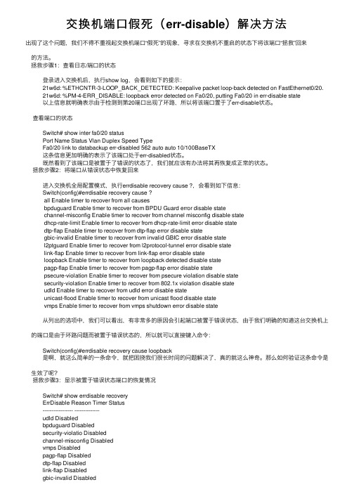
交换机端⼝假死(err-disable)解决⽅法出现了这个问题,我们不得不重视起交换机端⼝“假死”的现象,寻求在交换机不重启的状态下将该端⼝“拯救”回来 的⽅法。
拯救步骤1:查看⽇志/端⼝的状态 登录进⼊交换机后,执⾏show log,会看到如下的提⽰: 21w6d: %ETHCNTR-3-LOOP_BACK_DETECTED: Keepalive packet loop-back detected on FastEthernet0/20. 21w6d: %PM-4-ERR_DISABLE: loopback error detected on Fa0/20, putting Fa0/20 in err-disable state 以上信息就明确表⽰由于检测到第20端⼝出现了环路,所以将该端⼝置于了err-disable状态。
查看端⼝的状态 Switch# show inter fa0/20 status Port Name Status Vlan Duplex Speed Type Fa0/20 link to databackup err-disabled 562 auto auto 10/100BaseTX 这条信息更加明确的表⽰了该端⼝处于err-disabled状态。
既然看到了该端⼝是被置于了错误的状态了,我们就应该有办法将其再恢复成正常的状态。
拯救步骤2:将端⼝从错误状态中恢复回来 进⼊交换机全局配置模式,执⾏errdisable recovery cause ?,会看到如下信息: Switch(config)#errdisable recovery cause ? all Enable timer to recover from all causes bpduguard Enable timer to recover from BPDU Guard error disable state channel-misconfig Enable timer to recover from channel misconfig disable state dhcp-rate-limit Enable timer to recover from dhcp-rate-limit error disable state dtp-flap Enable timer to recover from dtp-flap error disable state gbic-invalid Enable timer to recover from invalid GBIC error disable state l2ptguard Enable timer to recover from l2protocol-tunnel error disable state link-flap Enable timer to recover from link-flap error disable state loopback Enable timer to recover from loopback detected disable state pagp-flap Enable timer to recover from pagp-flap error disable state psecure-violation Enable timer to recover from psecure violation disable state security-violation Enable timer to recover from 802.1x violation disable state udld Enable timer to recover from udld error disable state unicast-flood Enable timer to recover from unicast flood disable state vmps Enable timer to recover from vmps shutdown error disable state 从列出的选项中,我们可以看出,有⾮常多的原因会引起端⼝被置于错误状态,由于我们明确的知道这台交换机上 的端⼝是由于环路问题⽽被置于错误状态的,所以就可以直接键⼊命令: Switch(config)#errdisable recovery cause loopback 是啊,就这么简单的⼀条命令,就把困挠我们很长时间的问题解决了,真的就这么神奇。
解决oracle数据库监听器无法启动问题

解决oracle数据库监听器无法启动问题解决Oracle监听器服务不能启动的问题从客户端连接到服务器,出现了这个错误,ora12541-TNS : 没有监听器于是,在服务器中启动OracleOraHome92TNSListener服务,显示“在本地计算机无法启动OracleOraHome92TNSListener服务,错误3,系统找不到指定路径”。
然后执行:因为我的电脑数据监听程序没有问题,而且我过两天要出差去,刚好要演示系统,所以我的数据库一定不能有问题.这里就不将其更改给大家看了.用文字来表述吧LSNRCTL> status连接至(DESCRIPTION=(ADDRESS=(PROTOCOL=TCP)(HOST=robust)(PORT=1521)))TNS-01103: 地址的协议专用组件指定不正确TNS-12541: TNS:无监听器TNS-12560: TNS:协议适配器出现错误TNS-00511: 无监听器32-bit Windows Error: 61: Unknown errorLSNRCTL> start启动tnslsnr:请稍候...Failed to start service, error 3.TNS-12536: TNS:可能会阻碍*作TNS-12560: TNS:协议适配器出现错误TNS-00506: *作可能阻塞32-bit Windows Error: 997: Unknown errorLSNRCTL>三、在控制面板中启动服务,出现以下错误服务:在本地计算机无法启动OracleOraHome10gTNSListener 服务。
错误3:系统找不到指定的路径而且OracleOraHome1TNSListener服务的可执行文件的路径是空的。
四、进入注册表中修改ImagePath在运行处执行REGEDIT进入注册表到HKEY_LOCAL_MACHINE\SYSTEM\CurrentControlSet\Services\OracleOraHome10gTNSListener 发现ImagePath关键值没有了,增加他,选择可扩充字符串值,编辑字符串的数值数据为:d:\Oracle\Ora10g\BIN\TNSLSNR退出注册表。
解决重启系统或关机后再开机ansys10.0不能正常启动的方法
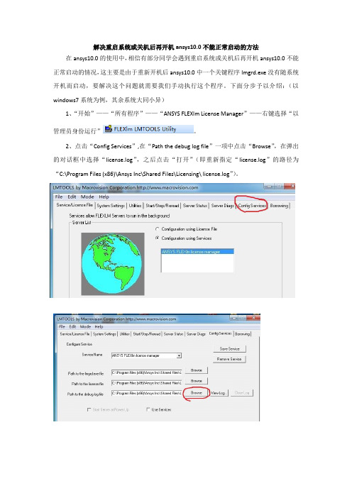
解决重启系统或关机后再开机ansys10.0不能正常启动的方法在ansys10.0的使用中,相信有部分同学会遇到重启系统或关机后再开机ansys10.0不能正常启动的情况,这主要是由于重新开机后ansys10.0中一个关键程序lmgrd.exe没有随系统开机而启动,要解决这个问题就需要我们手动执行这个程序。
下面分步予以介绍:(以windows7系统为例,其余系统大同小异)
1、“开始”——“所有程序”——“ANSYS FLEXlm License Manager”——右键选择“以管理员身份运行”。
2、点击“Config Services”,在“Path the debug log file”一项中点击“Browse”,在弹出的对话框中选择“license.log”,之后点击“打开”(即重新指定“license.log”的路径为“C:\Program Files (x86)\Ansys Inc\Shared Files\Licensing\ license.log”)。
4、点击“Save Service”,在弹出的对话框中选择“是”。
5、接下来点击“Start/Stop/Reread”,在弹出的对话框中按图示依次操作,直至出现“Server Start Successful”,即成功手动开启服务,ansys10.0使用恢复正常,以后重新开机重复1—5步操作即可。
友情提示:此方法为本人根据网上搜索总结得出,但似乎较麻烦,希望有更好解决办法的同学共享解决方法。
- 1、下载文档前请自行甄别文档内容的完整性,平台不提供额外的编辑、内容补充、找答案等附加服务。
- 2、"仅部分预览"的文档,不可在线预览部分如存在完整性等问题,可反馈申请退款(可完整预览的文档不适用该条件!)。
- 3、如文档侵犯您的权益,请联系客服反馈,我们会尽快为您处理(人工客服工作时间:9:00-18:30)。
YLCI684TL_0-室分基站TM3/7/8 自适应功能开启后
接入指标下降问题
YLCI684TL_0神木陕煤神南公司室分基站TM378 自适应功能开启后接入指标下降问题
法接入问题
【故障现象】:
从8月17 日开始,神木陕煤神南公司室分基站TDLTE 网络的RRC 建立成功率出现突降,从之前正常的约99%左右下降到80%左右。
现场拉网测试时发现占用室分基站时出现无法接入现象,RRC建立失败,此时无线环境良好,空口信令到RRCConnectionSetup 后无后续信令。
【原因分析】:
在17 日凌晨激活了一批参数修改WorkOrder,目的是统一现网参数设置,其中把
isInterTransmissionModeSwitchingEnabled 参数也进行了统一,即把全网小区,包括室分
小区的isInterTransmissionModeSwitchingEnabled 统一成TM378switchgenabled。
而室分
基站采用的是2 通道设备,是不支持TM7 和TM8 这两种传输模式的,特别是SISO 小区也不支持TM3,只支持TM1。
在ALU 的LPUG 中,对isInterTransmissionModeSwitchingEnabled 参数是如下描述的,其中注意事项是室分需要disableTM378 模式转换功能。
【解决方法】:
18 日点把所有室分基站的isInterTransmissionModeSwitchingEnabled 设置成
disable。
NPO 统计指标如下,可以看到在18 日点后指标恢复正常。
现场对室分基站进行参数调整验证,发现MIMO 的室分基站开启TM378 自适应功能后不会出现接入问题,而SISO 室分基站开启TM378 自适应后会出现接入问题,在关闭后正常。
【经验教训与总结】
对于isInterTransmissionModeSwitchingEnabled 参数一定要注意把室分基站设置成Disable,否则会出现无法接入问题。
后续建议SAM 里check Wo 执行时需要添加此过滤条。
