Q.763 - Formats and codes of the ISDN User Part of Signalling System No. 7
#光纤通信复习题英文

一 Make a choice 1) In graded-index optical fiber, the numerical aperture NA can be expressed as C.A. 21n n -B. ∆2aC. ∆2n 1D. 21n n a -2) In practical SMFs, the core diameter is just below the cutoff of the first higher-order mode; that is, for V slightly A.A. <2.4B. > 2.4C. =3D. =3.53) When the phase difference is an integral multiple of _2π_, the two modes will beat and the input polarization state will be reproduced.A. 2πB. πC. 1800D. π/24) It is well known that the total dispersion in the single-mode regime is composed of two components: C.A. mode-partition noise, inter- symbol InterferenceB. frequency chirp , modal dispersionC. material dispersion , waveguide dispersionD. modal dispersion , waveguide dispersion5) Which of the following codes cannot be transmitted in fibers B. A. CMI B. HDB3 C. 5B6B D. 8B1H6) Dispersion-shifted fiber (DSF) is a type of single-mode fiber designed to have zero dispersion near A nm. A. 1550 B. 850 C. 1310 D. 15107) To make sure that the APD photo detector works properly, a sufficiently D is applied across the p-n junction.A. high forward-bias voltageB. low forward-bias voltageC. low reverse-bias voltageD. high reverse-bias voltage8) A single mode fiber usually has a core diameter of A.A. 10mB. 62.5nmC. 125nmD. 50mm二Blank filling1) Each SDH frame comprising three areas: a section overhead area (SOH ), a pointer area, a payload area including the data to be transmitted.2) List three applications of FBG(fiber Bragg grating): filter 、Optical Add Drop Multiplexer(OADM) and dispersion compensator. 3) According to whether there is electric or magnetic field in the direction of propagation or not, transverse modes of light waves are classified into different types: TEM modes, TE modes, TM modes and hybrid modes.4) Transmission of information in an optical format is carried out not by frequency modulation of the carrier, but by varying the intensity of the optical power.5) Largely due to attenuation and dispersion, the optical signals undergo waveform distortion and decreased amplitude.6) Material dispersion occurs because the index of refraction varies as a function of the optical wavelength.7) ZDSF is a dispersion shifted single mode fiber that has the zero dispersion wavelength near the 1550 nm window, but outside the window actually used to transmit signals.8)A laser is constructed from three principal parts: a pump source, a gain medium, and an optical resonator.9)An optical fiber comprises at least two layers, a core and a cladding.10)Optical transmitter consists of optical source, a modulator and a channel coupler.11)Fiber refractive index profiles classify fibers as step-index fibers and graded-index fibers.12)BER (The bit error rate) performance and jitter are two important indicators in a opticaldigital communication system.13)LASER is a mechanism for emitting light within the electromagnetic radiation region of thespectrum, via the process of stimulated emission.14)There are two kinds of SOA:Fabry-Perot Amplifier (FPA) and Traveling-Wave Amplifier(TWA) .15)The principal noises associated with photo detectors that have no internal gain are quantumnoise, dark-current noise generated in the bulk material of the photodiode, and surface leakage current noise.16)In a step-index fiber, the refractive index of the core is uniform and undergoes an abruptchange at the core-cladding boundary. In graded-index fibers, the refractive index of the core varies gradually as a function of radial distance from the fiber center.17)If the input pulse excites both polarization components, it becomes broader as the twocomponents disperse along the fiber because of their different group velocities. This phenomenon is called the PMD.18)The most common semiconductor photo detector is the pin photodiode.19)The main cause of intrinsic absorption in the infrared region is the characteristic vibrationfrequency of atomic bonds.20)In SDH transmission structures, a TU (Tributary Unit) includes a low level VC and a TUPTR.21)Extrinsic absorption is caused by impurities introduced into the fiber material.22)Intramodal dispersion is a result of the group velocity being a function of the wavelength.23)The optical amplifiers is divided into 3 groups: semiconductor optical amplifier (SOA),optical fiber amplifier (OPA) and Raman amplifier (FRA).24)There are two kinds of directional couplers: a prism-fibre and a fibre-fibre lapped coupler.25)EDFA has three pumping structures: ①the forward pumping structure; ②the backwardpumping structure; ③ the double pumping structure.26) A laser consists of a gain medium inside a highly reflective optical cavity, as well as a meansto supply energy to the gain medium.27)Attenuation in an optical fiber is caused by absorption losses, scattering losses, and bendinglosses.28)STM-1 frames provide a transmission bit rate of 155 Mbit/s.29)From the point of view of the wave theory, light wave could be described as anelectromagnetic wave.30)Intermodal dispersion is a result of each mode having a different value of the group velocityat a single frequency.31) A typical optical digital communication system usually comprises three parts: transmitter,optical fiber channel, and receiver.32)The pin Photo detector structure consists of p and n regions separated by a very lightlyn-doped intrinsic (i) region.33)Please list three steps of SDH Multiplexing: mapping,aligning ,multiplexing.34)There are three variations of WDM that are commonly used: Broad WDM, Coarse WDM, and Dense WDM. 35)The STM-1 frame is the basic transmission format for SDH. The frame lasts for 125 microseconds; therefore there are 8000 frames per second. 36)In SDH frame structure, the SOH is made up of a regenerator section overhead (RSOH) and a multiplexing section overhead (MSOH). 37)The sensitivity of a photo detector in an optical fiber communication system is describable in terms of the minimum detectable optical power. 38)Please list three applications of EDFA in optical fiber communication system: as preamplifier of receiver 、as power amplifier of transmitter and as the optical repeater. 39) An optical isolator (optical diode), is an optical component which allows the transmission oflight in only one direction.三Interpretation of terms and phrases1) AON (all-optical network) 2) DBR (distributed Bragg reflector)3)FDDI (fiber distributed data interface) 4)HFC (hybrid fiber-coaxial)5)ISDN (integrated services digital network) 6)RA (raman amplifier)7)OC (optical carrier) 8)OTDM (optical time-division multiplexing)9)PON (passive optical network) 10)SCM (subcarrier multiplexing)11)SDH (synchronous digital hierarchy) 12)SPM (self-phase modulation)13)STS (synchronous transpor signal) 14)TW (traveling wave)15)WGA (waveguide-grating router) 16)IMD (intermodulation disortion)17)AWG (arrayed-waveguide grating) 18)AOTF (acousto-optic tunable filter)四 画图题1) Draw the element block of a Distributed forward Raman amplifier2) Draw an element diagram of a Double pump EDFA3) Draw a block diagram of a typical optical digital communication system and briefly describe the functions of each part.OutputInput EDF WDM IsolatorPump Laser Isolator Pump Laser WDMPump Laser outputfiber inputAn optical communication system consists of a transmitter, which encodes a message into an optical signal, a channel, which carries the signal to its destination, and a receiver, which reproduces the message from the received optical signal. The optical repeater is to extend the transmission distance of optical signal.4) Draw the element diagram of the application of optical amplifier.四 简答题1) Dispersion: Any phenomenon in which the velocity of propagation of any electromagnetic wave is wavelength dependent.2) Stimulated EmissionsIf a photon of energy hv 12 impinges on the system while the electron is still in its excited state, the electron is immediately stimulated to drop to the ground state and give off a photon of energy hv 12.3) There are 3 dispersion types in the optical fibers in general:1- Material Dispersion2- Waveguide Dispersion3- Polarization-Mode Dispersion4) Polarization mode dispersion (PMD) is due to slightly different velocity for each polarization mode because of the lack of perfectly symmetric & anisotropic of the fiber5) Laser is an optical oscillator. It comprises a resonant optical amplifier whose output is fed back into its input with matching phase. Any oscillator contains:1. An amplifier with a gain-saturated mechanism2. A feedback system3. A frequency selection mechanism4. An output coupling scheme Optical transmitter Repeater Opticalreceiverfiber fiber6) In thermal equilibrium the stimulated emission is essentially negligible, since the density of electrons in the excited state is very small, and optical emission is mainly because of the spontaneous emission. Stimulated emission will exceed absorption only if the population of the excited states is greater than that of the ground state. This condition is known as Population Inversion. Population inversion is achieved by various pumping techniques.7) Turn on DelayWhen the driving current suddenly jumps from low (I1 < Ith) to high (I2 > Ith) , (step input), there is a finite time before the laser will turn on8) The Quantum LimitFor an ideal photo-detector having unity quantum efficiency and producing no dark current, it is possible to find the minimum received optical power required for a specific BER performance in a digital system. This minimum received power level is known as the quantum limit.9) Gain flatness: The difference between the biggest gain and the smallest gain of the different frequency signal.10) The advantage of Raman amplifier: Simple fabricationLow noise, because amplifying action take place inside the ordinarily fiber.The wavelength can be selected in the low loss waveband.Very wide gain bandwidth.11) Micro bending Loss: microscopic bends of the fiber axis that can arise when the fibers are incorporated into cables. The power is dissipated through the micro bended fiber, because of the repetitive coupling of energy between guided modes & the leaky or radiation modes in the fiber.12) Gain saturation: when near saturation, the gain is nonlinear; saturation, the signal cannot be amplified.13) The disadvantage of Raman amplifier:Need large output power pump laser. As Raman Scattering, the energy is transferred from high frequency to low frequency. Cross talk will affect signal.14) The principal noises associated with photo detectors are:1- Quantum (Shot) noise: arises from statistical nature of the production and collection of photo-generated electrons upon optical illumination. It has been shown that the statistics follow a Poisson process.2- Dark current noise: is the current that continues to flow through the bias circuit in the absence of the light. This is the combination of bulk dark current, which is due to thermally generated e and h in the pn junction, and the surface dark current, due to surface defects, bias voltage and surface area.15) List the advantages of fiber-optic communications over other types of communication technologies.The advantage of optical fiber communication:1. Weight and Size2. Material cost (SiO2 is plentiful)3. Information Capacity4. No electromagnetic interference5. No electrical connection6. Distance between repeaters7. Better security8. Low crosstalk16) The fabrication of amplifierOptical isolator ,Optical multiplexer, EDF, Pump laser17) What are the advantages and disadvantages of SDH system as compared to PDH system? The main limitations of PDH are:Inability to identify individual channels in a higher-order bit stream;Insufficient capacity for network management;Most PDH network management is proprietary;There is no standardized definition of PDH bit rates greater than 140 Mbit/s; and,There are different hierarchies in use around the world. Specialized interface equipment is required to interwork the two hierarchies.18) List the types of fiber attenuation and dispersion.Absorbing\scattering and bending lossMaterial/ mode/ waveguide dispersion.19) The avalanche effect.The created carriers are accelerated by the high electric field, gaining enough energy to cause further impact ionization.20) Dynamic range:System dynamic range is the maximum optical power range to which any detector must be able to respond.21) Differentiate between step index and graded index optical fiber.Step index fiber has a core of one index of refraction; graded index fiber has a core in which the outside edge starts with a low index of refraction that gradually increases towards the center. 五 计算题1) Suppose two graded index fibers are misaligned with an axial offset of d=0.3a. Try to calculate the fraction of optical power coupled from the first fiber into the second fiber. (Parameter a is the core radius )The fraction of optical power coupled in the fiber :122222arccos()152262T P d d d d P a a a a π⎧⎫⎡⎤⎛⎫⎪⎪⎛⎫=---⎢⎥⎨⎬ ⎪ ⎪⎝⎭⎢⎥⎝⎭⎪⎪⎣⎦⎩⎭()()21220.320.15arccos(0.15)10.15532π⎧⎫⎛⎫⎪⎪⎡⎤=--- ⎪⎨⎬⎣⎦ ⎪⎪⎪⎝⎭⎩⎭0.748=Turn it into dB , obtain 10log 1.27T P dB P=- 1) A double-heterojunction InGaAsP LED emitting at a peak wavelength of 1310 nm has radiative and nonradiative recombination times of 30 and 100 ns, respectively. The drive current is 40 mA. Compute internal quantum efficiency and internal optical power. Then the internalquantum efficiency isthe internal power level is :2) A GaAs laser operating at800nm has a 500-µm length and a refractive index n=3.7.What are the frequency and wavelength spacing? From 2c Ln ν∆=,22Lnλλ∆= obtain: 86310812250010 3.7c GHz Ln ν-⨯∆===⨯⨯⨯,3) In a 100-ns pulse, 6×10⁶ photons at a wavelength of 1300nm fall on an In GaAs photo detector. On the average, 5.4×10⁶ electron-hole (e-h) pairs are generated.Please calculate the quantum efficiency.The quantum efficiencyNumber of e-h pairs generated= -----------------------------------------Number of incident photons=665.410610⨯⨯0.90= 4) Consider a graded-index optical fiber, core index n1=1.50 and the core cladding index difference Δ=0.01.Try to calculate:1. The cladding index n22. The numerical aperture NA解:已知:n 1 =1.50,∆=0.01,根据(1)77.0100/130/130/1111int =+=+=---nr r r τττηmW 92.21031.110602.1/103106256.604.077.0619834int int =⨯⨯⨯⨯⨯⋅⨯⨯⨯==---s m s J q Ihc P λη(2)由(1)式,可知2 n 12∆= n 12- n 22n 22= n 12(1-2∆)n 2= n 1∆-21将n 1、∆代入上式,可得n 2==1.5002.01-=1.5098.0⨯=1.50⨯0.98995=1.48491将n 1、∆代入(2)式,可得NA = n 1∆2=1.5002.0=1.50⨯0.14142=0.21213The numerical aperture NA isNA=∆21n =22.001.02560.1=⨯⨯The normalized frequency V=∆221λπn a =01.0231.15056.11416.3⨯⨯⨯=26.454>V C =2.4057) Consider a 30-km long optical fiber that has an attenuation of 0.8dB/km at 1300 nm. If 200µW of optical power is launched into the fiber, try to calculate the optical output power P out .First we turn the input signal power unit from mW into dBm63()20010()10log 10log 7.01110in in P W W P dBm dBm mW W --⎡⎤⨯⎡⎤===-⎢⎥⎢⎥⨯⎣⎦⎣⎦From ()10(0)l g ()P dB o km z P z α=, as z=30k, the output power is : ()()()10log 10log 11out in P W P W P dBm z out mW mW α⎡⎤⎡⎤==-⎢⎥⎢⎥⎣⎦⎣⎦7.0(0.8/)(30)31.0dBm dB km km dBm =--=- Also31.0/103(30)10(1)0.79100.79P km mW mW W μ--==⨯=8) A photodiode is constructed of GaAs, which has a band-gap energy of 1.43eV at 300K.What is the cutoff wavelength? The cutoff wavelength is ()()()()348196.62510310/8691.43 1.610/c g J s m s hc nm E eV J eV λ--⨯⋅⨯===⨯2) 一个折射率为3.6的GaAs 光源耦合进折射率为1.48的石英光纤中,如果光纤端面和光源在物理上紧密相接,于是分界面上发生菲涅尔反射:A GaAs optical source with a refractive index of 3.6 is coupled to a silica fiber that has a refractive index of 1.48 . If the fiber end and the source are in close physical contact , then , the Fresnel reflection at the interface is这相当于17.4%的发射功率反射回光源,与这一R 值相对应的耦合功率由下式给定:This value of R corresponds to a reflection of 17.4 percent of the emitted optical power back into the source . Given that由反射造成的功率损耗为:The power loss L in decibels is found from3) 有一个InGaAs 光电二极管,在100ns 内共入射了波长为1300 nm 的光子6×10⁶ 个,产生了 5.4×10⁶ 个电子空隙对,则其量子效率可以等于:In a 100-ns pulse, 6×10⁶ photons at a wavelength of 1300 nm fall on an InGaAs photodetector. On the average, 5.4x10⁶ electron-hole pairs are generated, quantum efficiency is .4) 能量为1.53 × 10⁻¹⁹ J 的光子入射到光电二极管上,此二极管的响应度为0.65 A/W ,如果入射光功率为10 mW ,则产生的光电流为:Photons of energy 1.53 × 10⁻¹⁹ J are incident on a photodiode which has a responsivity of 0.65 A/W. If the optical power level is 10 μW, the photocurrent is174.048.160.348.160.32211=⎪⎭⎫ ⎝⎛+-=⎪⎪⎭⎫ ⎝⎛+-=n n n n R ()em ittedcoupled P R P -=110log 10log(1)0.83dB coupled emitted P L R P ⎛⎫=-=--= ⎪⎝⎭%90106104.566=⨯⨯=ημA 5.6)μW 10()A/W 65.0(=⨯=ℜ=in p P I5) 如上图所示,波长范围为1300 nm - 1600 nm 的InGaAs pin ,量子效率约为90%,因此响应度为:As shown in above figure, for the wavelength range 1300 nm < λ < 1600 nm, the quantum efficiency for InGaAs is around 90%. So responsivity is当波长为1300 nm 时:Responsivity at 1300 nm is :6) 一种硅APD 在波长900 nm 时的量子效率为65%,假定0.5 mW 的光功率产生的倍增电流为10 mA ,试求倍增因子M 。
中国联通视频炫铃业务技术规范20081015

中国联通WCDMA数字蜂窝移动通信网视频炫铃业务技术要求China Unicom Digital Cellular Mobile Communication Network Specification for MRBT Service(V1.0)中国联合通信有限公司发布目次前言 (III)1 范围 (4)2 规范性引用文件 (4)3 缩略语 (5)4 业务概述 (6)4.1 业务描述 (6)4.2 业务使用方式 (6)4.3 业务开放范围 (7)5 系统体系结构(华为) (7)5.1概述 (7)5.2和核心网络的组网 (7)5.3系统外部组网 (8)5.3.1 各网元简述 (9)5.3.2 接口 (10)5.4系统总体结构 (11)5.4.1 各模块简述 (11)6 系统功能要求 (12)6.1业务管理功能 (12)6.1.1 业务受理功能 (12)6.1.2 业务基本功能 (14)6.2 业务统计功能 (16)6.3 SP管理 (17)7 业务流程 (17)7.1 基本流程 (17)7.2 无条件前转/关机前转呼叫的正常处理流程呼转 (20)7.3 网络决定忙前转/用户不可及前转的正常处理流程 (23)7.4 无应答前转/用户决定忙前转的正常处理流程 (26)7.5 异常情况的处理流程(不包括回落处理) (28)7.6 回落技术处理 (31)7.7 普通2G用户呼叫视频炫铃用户的呼叫处理 (34)7.8 跨运营商视频通话时的处理 (35)7.9 漫游情况下处理 (36)7.9.1 被叫视频炫铃用户漫游 (36)7.9.2 主叫用户漫游 (36)8 计费和结算 (36)8.1计费 (36)8.1.1 费用构成 (36)8.1.2 话单(参照其它已有增值业务系统规范的话单格式) (37)8.2结算 (37)9 视频铃音资源管理 (37)9.1 视频铃音格式(与视频电话的要求保持一致) (37)9.2 视频铃音与铃音盒编号.................................................................... 错误!未定义书签。
rfc2661.Layer Two Tunneling Protocol L2TP
Network Working Group W. Townsley Request for Comments: 2661 A. Valencia Category: Standards Track cisco Systems A. Rubens Ascend Communications G. Pall G. Zorn Microsoft Corporation B. Palter Redback Networks August 1999 Layer Two Tunneling Protocol "L2TP"Status of this MemoThis document specifies an Internet standards track protocol for the Internet community, and requests discussion and suggestions forimprovements. Please refer to the current edition of the "InternetOfficial Protocol Standards" (STD 1) for the standardization stateand status of this protocol. Distribution of this memo is unlimited.Copyright NoticeCopyright (C) The Internet Society (1999). All Rights Reserved.AbstractThis document describes the Layer Two Tunneling Protocol (L2TP). STD 51, RFC 1661 specifies multi-protocol access via PPP [RFC1661]. L2TP facilitates the tunneling of PPP packets across an interveningnetwork in a way that is as transparent as possible to both end-users and applications.Table of Contents1.0 Introduction (3)1.1 Specification of Requirements (4)1.2 Terminology (4)2.0 Topology (8)3.0 Protocol Overview (9)3.1 L2TP Header Format (9)3.2 Control Message Types (11)4.0 Control Message Attribute Value Pairs (12)4.1 AVP Format (13)4.2 Mandatory AVPs (14)4.3 Hiding of AVP Attribute Values (14)Townsley, et al. Standards Track [Page 1]4.4.1 AVPs Applicable To All Control Messages (17)4.4.2 Result and Error Codes (18)4.4.3 Control Connection Management AVPs (20)4.4.4 Call Management AVPs (27)4.4.5 Proxy LCP and Authentication AVPs (34)4.4.6 Call Status AVPs (39)5.0 Protocol Operation (41)5.1 Control Connection Establishment (41)5.1.1 Tunnel Authentication (42)5.2 Session Establishment (42)5.2.1 Incoming Call Establishment (42)5.2.2 Outgoing Call Establishment (43)5.3 Forwarding PPP Frames (43)5.4 Using Sequence Numbers on the Data Channel (44)5.5 Keepalive (Hello) (44)5.6 Session Teardown (45)5.7 Control Connection Teardown (45)5.8 Reliable Delivery of Control Messages (46)6.0 Control Connection Protocol Specification (48)6.1 Start-Control-Connection-Request (SCCRQ) (48)6.2 Start-Control-Connection-Reply (SCCRP) (48)6.3 Start-Control-Connection-Connected (SCCCN) (49)6.4 Stop-Control-Connection-Notification (StopCCN) (49)6.5 Hello (HELLO) (49)6.6 Incoming-Call-Request (ICRQ) (50)6.7 Incoming-Call-Reply (ICRP) (51)6.8 Incoming-Call-Connected (ICCN) (51)6.9 Outgoing-Call-Request (OCRQ) (52)6.10 Outgoing-Call-Reply (OCRP) (53)6.11 Outgoing-Call-Connected (OCCN) (53)6.12 Call-Disconnect-Notify (CDN) (53)6.13 WAN-Error-Notify (WEN) (54)6.14 Set-Link-Info (SLI) (54)7.0 Control Connection State Machines (54)7.1 Control Connection Protocol Operation (55)7.2 Control Connection States (56)7.2.1 Control Connection Establishment (56)7.3 Timing considerations (58)7.4 Incoming calls (58)7.4.1 LAC Incoming Call States (60)7.4.2 LNS Incoming Call States (62)7.5 Outgoing calls (63)7.5.1 LAC Outgoing Call States (64)7.5.2 LNS Outgoing Call States (66)7.6 Tunnel Disconnection (67)8.0 L2TP Over Specific Media (67)8.1 L2TP over UDP/IP (68)Townsley, et al. Standards Track [Page 2]9.0 Security Considerations (69)9.1 Tunnel Endpoint Security (70)9.2 Packet Level Security (70)9.3 End to End Security (70)9.4 L2TP and IPsec (71)9.5 Proxy PPP Authentication (71)10.0 IANA Considerations (71)10.1 AVP Attributes (71)10.2 Message Type AVP Values (72)10.3 Result Code AVP Values (72)10.3.1 Result Code Field Values (72)10.3.2 Error Code Field Values (72)10.4 Framing Capabilities & Bearer Capabilities (72)10.5 Proxy Authen Type AVP Values (72)10.6 AVP Header Bits (73)11.0 References (73)12.0 Acknowledgments (74)13.0 Authors’ Addresses (75)Appendix A: Control Channel Slow Start and CongestionAvoidance (76)Appendix B: Control Message Examples (77)Appendix C: Intellectual Property Notice (79)Full Copyright Statement (80)1.0 IntroductionPPP [RFC1661] defines an encapsulation mechanism for transportingmultiprotocol packets across layer 2 (L2) point-to-point links.Typically, a user obtains a L2 connection to a Network Access Server (NAS) using one of a number of techniques (e.g., dialup POTS, ISDN,ADSL, etc.) and then runs PPP over that connection. In such aconfiguration, the L2 termination point and PPP session endpointreside on the same physical device (i.e., the NAS).L2TP extends the PPP model by allowing the L2 and PPP endpoints toreside on different devices interconnected by a packet-switchednetwork. With L2TP, a user has an L2 connection to an accessconcentrator (e.g., modem bank, ADSL DSLAM, etc.), and theconcentrator then tunnels individual PPP frames to the NAS. Thisallows the actual processing of PPP packets to be divorced from thetermination of the L2 circuit.One obvious benefit of such a separation is that instead of requiring the L2 connection terminate at the NAS (which may require along-distance toll charge), the connection may terminate at a (local) circuit concentrator, which then extends the logical PPP session over Townsley, et al. Standards Track [Page 3]a shared infrastructure such as frame relay circuit or the Internet.From the user’s perspective, there is no functional difference between having the L2 circuit terminate in a NAS directly or using L2TP.L2TP may also solve the multilink hunt-group splitting problem.Multilink PPP [RFC1990] requires that all channels composing amultilink bundle be grouped at a single Network Access Server (NAS).Due to its ability to project a PPP session to a location other thanthe point at which it was physically received, L2TP can be used tomake all channels terminate at a single NAS. This allows multilinkoperation even when the calls are spread across distinct physicalNASs.This document defines the necessary control protocol for on-demandcreation of tunnels between two nodes and the accompanyingencapsulation for multiplexing multiple, tunneled PPP sessions.1.1 Specification of RequirementsThe key words "MUST", "MUST NOT", "REQUIRED", "SHALL", "SHALL NOT","SHOULD", "SHOULD NOT", "RECOMMENDED", "MAY", and "OPTIONAL" in thisdocument are to be interpreted as described in [RFC2119].1.2 TerminologyAnalog ChannelA circuit-switched communication path which is intended to carry3.1 kHz audio in each direction.Attribute Value Pair (AVP)The variable length concatenation of a unique Attribute(represented by an integer) and a Value containing the actualvalue identified by the attribute. Multiple AVPs make up ControlMessages which are used in the establishment, maintenance, andteardown of tunnels.CallA connection (or attempted connection) between a Remote System and LAC. For example, a telephone call through the PSTN. A Call(Incoming or Outgoing) which is successfully established between a Remote System and LAC results in a corresponding L2TP Sessionwithin a previously established Tunnel between the LAC and LNS.(See also: Session, Incoming Call, Outgoing Call).Townsley, et al. Standards Track [Page 4]Called NumberAn indication to the receiver of a call as to what telephonenumber the caller used to reach it.Calling NumberAn indication to the receiver of a call as to the telephone number of the caller.CHAPChallenge Handshake Authentication Protocol [RFC1994], a PPPcryptographic challenge/response authentication protocol in which the cleartext password is not passed over the line.Control ConnectionA control connection operates in-band over a tunnel to control the establishment, release, and maintenance of sessions and of thetunnel itself.Control MessagesControl messages are exchanged between LAC and LNS pairs,operating in-band within the tunnel protocol. Control messagesgovern aspects of the tunnel and sessions within the tunnel.Digital ChannelA circuit-switched communication path which is intended to carrydigital information in each direction.DSLAMDigital Subscriber Line (DSL) Access Module. A network device used in the deployment of DSL service. This is typically a concentrator of individual DSL lines located in a central office (CO) or local exchange.Incoming CallA Call received at an LAC to be tunneled to an LNS (see Call,Outgoing Call).Townsley, et al. Standards Track [Page 5]L2TP Access Concentrator (LAC)A node that acts as one side of an L2TP tunnel endpoint and is apeer to the L2TP Network Server (LNS). The LAC sits between anLNS and a remote system and forwards packets to and from each.Packets sent from the LAC to the LNS requires tunneling with theL2TP protocol as defined in this document. The connection fromthe LAC to the remote system is either local (see: Client LAC) or a PPP link.L2TP Network Server (LNS)A node that acts as one side of an L2TP tunnel endpoint and is apeer to the L2TP Access Concentrator (LAC). The LNS is thelogical termination point of a PPP session that is being tunneled from the remote system by the LAC.Management Domain (MD)A network or networks under the control of a singleadministration, policy or system. For example, an LNS’s Management Domain might be the corporate network it serves. An LAC’sManagement Domain might be the Internet Service Provider that owns and manages it.Network Access Server (NAS)A device providing local network access to users across a remoteaccess network such as the PSTN. An NAS may also serve as an LAC, LNS or both.Outgoing CallA Call placed by an LAC on behalf of an LNS (see Call, IncomingCall).PeerWhen used in context with L2TP, peer refers to either the LAC orLNS. An LAC’s Peer is an LNS and vice versa. When used in context with PPP, a peer is either side of the PPP connection.POTSPlain Old Telephone Service.Townsley, et al. Standards Track [Page 6]Remote SystemAn end-system or router attached to a remote access network (i.e.a PSTN), which is either the initiator or recipient of a call.Also referred to as a dial-up or virtual dial-up client.SessionL2TP is connection-oriented. The LNS and LAC maintain state foreach Call that is initiated or answered by an LAC. An L2TP Session is created between the LAC and LNS when an end-to-end PPPconnection is established between a Remote System and the LNS.Datagrams related to the PPP connection are sent over the Tunnelbetween the LAC and LNS. There is a one to one relationshipbetween established L2TP Sessions and their associated Calls. (See also: Call).TunnelA Tunnel exists between a LAC-LNS pair. The Tunnel consists of aControl Connection and zero or more L2TP Sessions. The Tunnelcarries encapsulated PPP datagrams and Control Messages betweenthe LAC and the LNS.Zero-Length Body (ZLB) MessageA control packet with only an L2TP header. ZLB messages are usedfor explicitly acknowledging packets on the reliable controlchannel.Townsley, et al. Standards Track [Page 7]2.0 TopologyThe following diagram depicts a typical L2TP scenario. The goal is to tunnel PPP frames between the Remote System or LAC Client and an LNS located at a Home LAN.[Home LAN][LAC Client]----------+ |____|_____ +--[Host]| | |[LAC]---------| Internet |-----[LNS]-----+| |__________| |_____|_____ :| || PSTN |[Remote]--| Cloud |[System] | | [Home LAN]|___________| || ______________ +---[Host]| | | |[LAC]-------| Frame Relay |---[LNS]-----+| or ATM Cloud | ||______________| :The Remote System initiates a PPP connection across the PSTN Cloud to an LAC. The LAC then tunnels the PPP connection across the Internet, Frame Relay, or ATM Cloud to an LNS whereby access to a Home LAN isobtained. The Remote System is provided addresses from the HOME LANvia PPP NCP negotiation. Authentication, Authorization and Accounting may be provided by the Home LAN’s Management Domain as if the userwere connected to a Network Access Server directly.A LAC Client (a Host which runs L2TP natively) may also participatein tunneling to the Home LAN without use of a separate LAC. In thiscase, the Host containing the LAC Client software already has aconnection to the public Internet. A "virtual" PPP connection is then created and the local L2TP LAC Client software creates a tunnel tothe LNS. As in the above case, Addressing, Authentication,Authorization and Accounting will be provided by the Home LAN’sManagement Domain.Townsley, et al. Standards Track [Page 8]3.0 Protocol OverviewL2TP utilizes two types of messages, control messages and datamessages. Control messages are used in the establishment, maintenance and clearing of tunnels and calls. Data messages are used toencapsulate PPP frames being carried over the tunnel. Controlmessages utilize a reliable Control Channel within L2TP to guarantee delivery (see section 5.1 for details). Data messages are notretransmitted when packet loss occurs.+-------------------+| PPP Frames |+-------------------+ +-----------------------+| L2TP Data Messages| | L2TP Control Messages |+-------------------+ +-----------------------+| L2TP Data Channel | | L2TP Control Channel || (unreliable) | | (reliable) |+------------------------------------------------+| Packet Transport (UDP, FR, ATM, etc.) |+------------------------------------------------+Figure 3.0 L2TP Protocol StructureFigure 3.0 depicts the relationship of PPP frames and ControlMessages over the L2TP Control and Data Channels. PPP Frames arepassed over an unreliable Data Channel encapsulated first by an L2TP header and then a Packet Transport such as UDP, Frame Relay, ATM,etc. Control messages are sent over a reliable L2TP Control Channelwhich transmits packets in-band over the same Packet Transport.Sequence numbers are required to be present in all control messagesand are used to provide reliable delivery on the Control Channel.Data Messages may use sequence numbers to reorder packets and detect lost packets.All values are placed into their respective fields and sent innetwork order (high order octets first).3.1 L2TP Header FormatL2TP packets for the control channel and data channel share a common header format. In each case where a field is optional, its space does not exist in the message if the field is marked not present. Notethat while optional on data messages, the Length, Ns, and Nr fieldsmarked as optional below, are required to be present on all controlmessages.Townsley, et al. Standards Track [Page 9]This header is formatted:0 1 2 30 1 2 3 4 5 6 7 8 9 0 1 2 3 4 5 6 7 8 9 0 1 2 3 4 5 6 7 8 9 0 1+-+-+-+-+-+-+-+-+-+-+-+-+-+-+-+-+-+-+-+-+-+-+-+-+-+-+-+-+-+-+-+-+|T|L|x|x|S|x|O|P|x|x|x|x| Ver | Length (opt) |+-+-+-+-+-+-+-+-+-+-+-+-+-+-+-+-+-+-+-+-+-+-+-+-+-+-+-+-+-+-+-+-+| Tunnel ID | Session ID |+-+-+-+-+-+-+-+-+-+-+-+-+-+-+-+-+-+-+-+-+-+-+-+-+-+-+-+-+-+-+-+-+| Ns (opt) | Nr (opt) |+-+-+-+-+-+-+-+-+-+-+-+-+-+-+-+-+-+-+-+-+-+-+-+-+-+-+-+-+-+-+-+-+| Offset Size (opt) | Offset pad... (opt)+-+-+-+-+-+-+-+-+-+-+-+-+-+-+-+-+-+-+-+-+-+-+-+-+-+-+-+-+-+-+-+-+Figure 3.1 L2TP Message HeaderThe Type (T) bit indicates the type of message. It is set to 0 for a data message and 1 for a control message.If the Length (L) bit is 1, the Length field is present. This bitMUST be set to 1 for control messages.The x bits are reserved for future extensions. All reserved bits MUST be set to 0 on outgoing messages and ignored on incoming messages.If the Sequence (S) bit is set to 1 the Ns and Nr fields are present. The S bit MUST be set to 1 for control messages.If the Offset (O) bit is 1, the Offset Size field is present. The Obit MUST be set to 0 (zero) for control messages.If the Priority (P) bit is 1, this data message should receivepreferential treatment in its local queuing and transmission. LCPecho requests used as a keepalive for the link, for instance, should generally be sent with this bit set to 1. Without it, a temporaryinterval of local congestion could result in interference withkeepalive messages and unnecessary loss of the link. This feature is only for use with data messages. The P bit MUST be set to 0 for allcontrol messages.Ver MUST be 2, indicating the version of the L2TP data message header described in this document. The value 1 is reserved to permitdetection of L2F [RFC2341] packets should they arrive intermixed with L2TP packets. Packets received with an unknown Ver field MUST bediscarded.The Length field indicates the total length of the message in octets. Townsley, et al. Standards Track [Page 10]Tunnel ID indicates the identifier for the control connection. L2TPtunnels are named by identifiers that have local significance only.That is, the same tunnel will be given different Tunnel IDs by eachend of the tunnel. Tunnel ID in each message is that of the intended recipient, not the sender. Tunnel IDs are selected and exchanged asAssigned Tunnel ID AVPs during the creation of a tunnel.Session ID indicates the identifier for a session within a tunnel.L2TP sessions are named by identifiers that have local significanceonly. That is, the same session will be given different Session IDsby each end of the session. Session ID in each message is that of the intended recipient, not the sender. Session IDs are selected andexchanged as Assigned Session ID AVPs during the creation of asession.Ns indicates the sequence number for this data or control message,beginning at zero and incrementing by one (modulo 2**16) for eachmessage sent. See Section 5.8 and 5.4 for more information on usingthis field.Nr indicates the sequence number expected in the next control message to be received. Thus, Nr is set to the Ns of the last in-ordermessage received plus one (modulo 2**16). In data messages, Nr isreserved and, if present (as indicated by the S-bit), MUST be ignored upon receipt. See section 5.8 for more information on using thisfield in control messages.The Offset Size field, if present, specifies the number of octetspast the L2TP header at which the payload data is expected to start. Actual data within the offset padding is undefined. If the offsetfield is present, the L2TP header ends after the last octet of theoffset padding.3.2 Control Message TypesThe Message Type AVP (see section 4.4.1) defines the specific type of control message being sent. Recall from section 3.1 that this is only for control messages, that is, messages with the T-bit set to 1. Townsley, et al. Standards Track [Page 11]This document defines the following control message types (seeSection 6.1 through 6.14 for details on the construction and use ofeach message):Control Connection Management0 (reserved)1 (SCCRQ) Start-Control-Connection-Request2 (SCCRP) Start-Control-Connection-Reply3 (SCCCN) Start-Control-Connection-Connected4 (StopCCN) Stop-Control-Connection-Notification5 (reserved)6 (HELLO) HelloCall Management7 (OCRQ) Outgoing-Call-Request8 (OCRP) Outgoing-Call-Reply9 (OCCN) Outgoing-Call-Connected10 (ICRQ) Incoming-Call-Request11 (ICRP) Incoming-Call-Reply12 (ICCN) Incoming-Call-Connected13 (reserved)14 (CDN) Call-Disconnect-NotifyError Reporting15 (WEN) WAN-Error-NotifyPPP Session Control16 (SLI) Set-Link-Info4.0 Control Message Attribute Value PairsTo maximize extensibility while still permitting interoperability, a uniform method for encoding message types and bodies is usedthroughout L2TP. This encoding will be termed AVP (Attribute-ValuePair) in the remainder of this document.Townsley, et al. Standards Track [Page 12]4.1 AVP FormatEach AVP is encoded as:0 1 2 30 1 2 3 4 5 6 7 8 9 0 1 2 3 4 5 6 7 8 9 0 1 2 3 4 5 6 7 8 9 0 1+-+-+-+-+-+-+-+-+-+-+-+-+-+-+-+-+-+-+-+-+-+-+-+-+-+-+-+-+-+-+-+-+|M|H| rsvd | Length | Vendor ID |+-+-+-+-+-+-+-+-+-+-+-+-+-+-+-+-+-+-+-+-+-+-+-+-+-+-+-+-+-+-+-+-+| Attribute Type | Attribute Value...+-+-+-+-+-+-+-+-+-+-+-+-+-+-+-+-+-+-+-+-+-+-+-+-+-+-+-+-+-+-+-+-+[until Length is reached]... |+-+-+-+-+-+-+-+-+-+-+-+-+-+-+-+-+-+-+-+-+-+-+-+-+-+-+-+-+-+-+-+-+The first six bits are a bit mask, describing the general attributes of the AVP.Two bits are defined in this document, the remaining are reserved for future extensions. Reserved bits MUST be set to 0. An AVP receivedwith a reserved bit set to 1 MUST be treated as an unrecognized AVP. Mandatory (M) bit: Controls the behavior required of animplementation which receives an AVP which it does not recognize. If the M bit is set on an unrecognized AVP within a message associatedwith a particular session, the session associated with this messageMUST be terminated. If the M bit is set on an unrecognized AVP within a message associated with the overall tunnel, the entire tunnel (and all sessions within) MUST be terminated. If the M bit is not set, an unrecognized AVP MUST be ignored. The control message must thencontinue to be processed as if the AVP had not been present.Hidden (H) bit: Identifies the hiding of data in the Attribute Value field of an AVP. This capability can be used to avoid the passing of sensitive data, such as user passwords, as cleartext in an AVP.Section 4.3 describes the procedure for performing AVP hiding.Length: Encodes the number of octets (including the Overall Lengthand bitmask fields) contained in this AVP. The Length may becalculated as 6 + the length of the Attribute Value field in octets. The field itself is 10 bits, permitting a maximum of 1023 octets ofdata in a single AVP. The minimum Length of an AVP is 6. If thelength is 6, then the Attribute Value field is absent.Vendor ID: The IANA assigned "SMI Network Management PrivateEnterprise Codes" [RFC1700] value. The value 0, corresponding toIETF adopted attribute values, is used for all AVPs defined withinthis document. Any vendor wishing to implement their own L2TPextensions can use their own Vendor ID along with private Attribute Townsley, et al. Standards Track [Page 13]values, guaranteeing that they will not collide with any othervendor’s extensions, nor with future IETF extensions. Note that there are 16 bits allocated for the Vendor ID, thus limiting this featureto the first 65,535 enterprises.Attribute Type: A 2 octet value with a unique interpretation acrossall AVPs defined under a given Vendor ID.Attribute Value: This is the actual value as indicated by the Vendor ID and Attribute Type. It follows immediately after the AttributeType field, and runs for the remaining octets indicated in the Length (i.e., Length minus 6 octets of header). This field is absent if the Length is 6.4.2 Mandatory AVPsReceipt of an unknown AVP that has the M-bit set is catastrophic tothe session or tunnel it is associated with. Thus, the M bit shouldonly be defined for AVPs which are absolutely crucial to properoperation of the session or tunnel. Further, in the case where theLAC or LNS receives an unknown AVP with the M-bit set and shuts down the session or tunnel accordingly, it is the full responsibility ofthe peer sending the Mandatory AVP to accept fault for causing annon-interoperable situation. Before defining an AVP with the M-bitset, particularly a vendor-specific AVP, be sure that this is theintended consequence.When an adequate alternative exists to use of the M-bit, it should be utilized. For example, rather than simply sending an AVP with the M- bit set to determine if a specific extension exists, availability may be identified by sending an AVP in a request message and expecting a corresponding AVP in a reply message.Use of the M-bit with new AVPs (those not defined in this document)MUST provide the ability to configure the associated feature off,such that the AVP is either not sent, or sent with the M-bit not set.4.3 Hiding of AVP Attribute ValuesThe H bit in the header of each AVP provides a mechanism to indicate to the receiving peer whether the contents of the AVP are hidden orpresent in cleartext. This feature can be used to hide sensitivecontrol message data such as user passwords or user IDs.The H bit MUST only be set if a shared secret exists between the LAC and LNS. The shared secret is the same secret that is used for tunnel authentication (see Section 5.1.1). If the H bit is set in any Townsley, et al. Standards Track [Page 14]AVP(s) in a given control message, a Random Vector AVP must also bepresent in the message and MUST precede the first AVP having an H bit of 1.Hiding an AVP value is done in several steps. The first step is totake the length and value fields of the original (cleartext) AVP and encode them into a Hidden AVP Subformat as follows:0 1 2 30 1 2 3 4 5 6 7 8 9 0 1 2 3 4 5 6 7 8 9 0 1 2 3 4 5 6 7 8 9 0 1+-+-+-+-+-+-+-+-+-+-+-+-+-+-+-+-+-+-+-+-+-+-+-+-+-+-+-+-+-+-+-+-+| Length of Original Value | Original Attribute Value ...+-+-+-+-+-+-+-+-+-+-+-+-+-+-+-+-+-+-+-+-+-+-+-+-+-+-+-+-+-+-+-+-+... | Padding ...+-+-+-+-+-+-+-+-+-+-+-+-+-+-+-+-+-+-+-+-+-+-+-+-+-+-+-+-+-+-+-+-+Length of Original Attribute Value: This is length of the OriginalAttribute Value to be obscured in octets. This is necessary todetermine the original length of the Attribute Value which is lostwhen the additional Padding is added.Original Attribute Value: Attribute Value that is to be obscured.Padding: Random additional octets used to obscure length of theAttribute Value that is being hidden.To mask the size of the data being hidden, the resulting subformatMAY be padded as shown above. Padding does NOT alter the value placed in the Length of Original Attribute Value field, but does alter thelength of the resultant AVP that is being created. For example, If an Attribute Value to be hidden is 4 octets in length, the unhidden AVP length would be 10 octets (6 + Attribute Value length). After hiding, the length of the AVP will become 6 + Attribute Value length + sizeof the Length of Original Attribute Value field + Padding. Thus, ifPadding is 12 octets, the AVP length will be 6 + 4 + 2 + 12 = 24octets.Next, An MD5 hash is performed on the concatenation of:+ the 2 octet Attribute number of the AVP+ the shared secret+ an arbitrary length random vectorThe value of the random vector used in this hash is passed in thevalue field of a Random Vector AVP. This Random Vector AVP must beplaced in the message by the sender before any hidden AVPs. The same random vector may be used for more than one hidden AVP in the same Townsley, et al. Standards Track [Page 15]message. If a different random vector is used for the hiding ofsubsequent AVPs then a new Random Vector AVP must be placed in thecommand message before the first AVP to which it applies.The MD5 hash value is then XORed with the first 16 octet (or less)segment of the Hidden AVP Subformat and placed in the Attribute Value field of the Hidden AVP. If the Hidden AVP Subformat is less than 16 octets, the Subformat is transformed as if the Attribute Value field had been padded to 16 octets before the XOR, but only the actualoctets present in the Subformat are modified, and the length of theAVP is not altered.If the Subformat is longer than 16 octets, a second one-way MD5 hash is calculated over a stream of octets consisting of the shared secret followed by the result of the first XOR. That hash is XORed with the second 16 octet (or less) segment of the Subformat and placed in the corresponding octets of the Value field of the Hidden AVP.If necessary, this operation is repeated, with the shared secret used along with each XOR result to generate the next hash to XOR the next segment of the value with.The hiding method was adapted from RFC 2138 [RFC2138] which was taken from the "Mixing in the Plaintext" section in the book "NetworkSecurity" by Kaufman, Perlman and Speciner [KPS]. A detailedexplanation of the method follows:Call the shared secret S, the Random Vector RV, and the AttributeValue AV. Break the value field into 16-octet chunks p1, p2, etc.with the last one padded at the end with random data to a 16-octetboundary. Call the ciphertext blocks c(1), c(2), etc. We will also define intermediate values b1, b2, etc.b1 = MD5(AV + S + RV) c(1) = p1 xor b1b2 = MD5(S + c(1)) c(2) = p2 xor b2. .. .. .bi = MD5(S + c(i-1)) c(i) = pi xor biThe String will contain c(1)+c(2)+...+c(i) where + denotesconcatenation.On receipt, the random vector is taken from the last Random VectorAVP encountered in the message prior to the AVP to be unhidden. The above process is then reversed to yield the original value.Townsley, et al. Standards Track [Page 16]。
无线网络优化中Disconnect Cause Codes原因
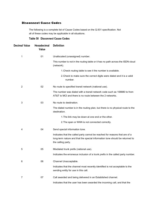
Disconnect Cause CodesThe following is a complete list of Cause Codes based on the Q.931 specification. Notall of these codes may be applicable in all situations.Table 50 Disconnect Cause Code sDecimal Value HexadecimalDefinitionValue1 01 Unallocated (unassigned) number.This number is not in the routing table or it has no path across the ISDN cloud(network).1. C heck routing table to see it the number is available.2. C heck to make sure the correct digits were dialed and it is a validnumber.2 02 No route to specified transit network (national use).The number was dialed with a transit network code such as 108880 to fromAT&T to MCI and there is no route between the 2 networks.3 03 No route to destination.The dialed number is in the routing plan, but there is no physical route to thedestination.1. T he link may be down at one end or the other.2. T he span or WAN is not connected correctly.4 04 Send special information tone.Indicates that the called party cannot be reached for reasons that are of along-term nature and that the special information tone should be returned tothe calling party.5 05 Misdialed trunk prefix (national use).Indicates the erroneous inclusion of a trunk prefix in the called party number.6 06 Channel Unacceptable.Indicates that the channel most recently identified is not acceptable to thesending entity for use in this call.7 07 Call awarded and being delivered in an Established channel.Indicates that the user has been awarded the incoming call, and that theincoming call is being connected to a channel already established to that userfor similar calls (e.g. packet-mode virtual calls).8 08 Pre-Emption.Indicates that the call is being pre-empted.0 09 Pre-Emption Circuit reserved for reuse.Indicates that the call is being cleared because one of the users involved inthe call has requested that the call be cleared.16 10 Normal Call Clearing.This is one of the most common cause codes and is received for manyreasons. It usually occurs because someone hung up the call at one side orthe other.17 11 User Busy.The number dialed is busy and cannot receive any more calls.18 12 No User Responding.The called party does not respond to the call, or does not wish to answer thecall.19 13 No Answer from User (User Alerted).The called party has been alerted to the incoming call, but does not respondwith a connect indication within a prescribed period of time.NoteThis cause is not necessarily generated by Q.931 procedures but may begenerated by internal network timers.20 14 Subscriber Absent.Used when a mobile station has logged off, radio contact is not obtained witha mobile station or if a personal telecommunications user is temporarily notaddressable at any user-network interface.21 15 Call Rejected.Indicates that the equipment sending this cause does not wish to accept thiscall, alth9ough it could have accepted the call because the equipmentsending this cause is neither busy nor incompatible. May also be generatedby the network, indicating that the call was cleared due to a supplementaryservice constraint.22 16 Number Changed.This is returned to a calling party when the called party number indicated bythe calling party is no longer assigned. The new called party number mayoptionally be included in the diagnostic field. If a network does not supportthis cause value, cause number 1 shall be used.26 1A Non-Selected User Clearing.Indicates that the user has not been awarded the incoming call.27 1B Destination Out-of-Order.This is a working number, but the span to the destination is not active or thereis a problem sending messages to this destination.28 1C Invalid Number Format (address incomplete).Indicates that the called party cannot be reached because the called partynumber is not in a valid format or is not complete. This can happen when youare calling out using a network type number (enterprise) when you should becalling out Unknown or National for the Type of Number (TON).29 1D Facility Rejected.This cause is returned when a supplementary service requested by the usercannot be provided by the network.30 1E Response to STATUS ENQUIRY.This cause is included in the STATUS message when the reason forgenerating the STATUS message was the prior receipt of a STATUSENQUIRY message.31 1F Normal, Unspecified.This is a very common cause code and happens when the network is notable to determine what to do with the call being made.34 22 No Circuit/Channel Available.There are no channels available to handle this call. This may happen if thedestination gateway is full with calls.38 26 Network Out-of-Order.Indicates that the network is not functioning correctly and that the condition islikely to last a relatively long period of time.39 27 Permanent Frame Mode Connection Out-of-Service.This cause is included in a STATUS message to indicate that a permanentlyestablished frame mode connection is out-of-service.40 28 Permanent Frame Mode Connection Operational.This cause is included in a STATUS message to indicate that a permanentlyestablished frame mode connection is operational and capable of carryinguser information.41 29 Temporary Failure.The call was disconnected due to a network failure. The network is notfunctioning correctly and that the condition is not likely to last a long period oftime; e.g., the user may wish to try another call attempt almost immediately.42 2A Switching Equipment Congestion.Indicates that the switching equipment generating this cause is experiencinga period of high traffic.43 2B Access Information Discarded.Indicates that the network could not deliver access information to the remoteuser as requested, i.e., user-to-user information, low layer compatibility, highlayer compatibility, or sub-address, as indicated in the diagnostic.44 2C Requested Circuit/Channel not Available.This cause is returned when the circuit or channel indicated by the requestingentity cannot be provided by the other side of the interface. This may happenwhen you get in a glare condition: Both sides are selected top-down orbottom-up channel hunting.47 2F Resource Unavailable, Unspecified.Used to report a resource unavailable event only when no other cause in theresource unavailable class applies.49 31 Quality of Service Not Available.Used to report that the requested Quality of Service, as defined inRecommendation X.213, cannot be provided (e.g., throughput or transit delaycannot be supported).50 32 Requested Facility Not Subscribed.This cause indicates that the user has requested a supplementary servicewhich is implemented by the equipment which generated this cause, but theuser is not authorized to use.53 35 Outgoing Calls Barred Within Closed User Group (CUG).Indicates that although the calling party is a member of the CUG for theoutgoing CUG call, outgoing calls are not allowed for this member of theCUG.55 37 Incoming Calls Barred within CUG.Indicates that although the called party is a member of the CUG for theincoming CUG call, incoming calls are not allowed to this member of theCUG.57 39 Bearer Capability Not Authorized.Indicates that the user has requested a bearer capability which isimplemented by the equipment that generated this cause but the user is notauthorized to use.58 3A Bearer Capability Not Presently Available.Indicates that the user has requested a bearer capability, which isimplemented by the equipment that generated this cause but which is notavailable at this time.62 3E Inconsistency in Designated Outgoing Access Information and SubscriberClass.This cause indicates that there is an inconsistency in the designated outgoingaccess information and subscriber class.63 3F Service or Option Not Available, Unspecified.Used to report a service or option not available event only when no othercause in the service or option not available class applies.65 41 Bearer Capability Not Implemented.Indicates that the equipment sending this cause does not support the bearercapability requested (i.e., requesting 64kb data when only speech issupported).66 42 Channel Type Not Implemented.Indicates that the equipment sending this cause does not support the channeltype requested.69 45 Requested Facility Not Implemented.Indicates that the equipment sending this cause does not support therequested supplementary service.70 46 Only Restricted Digital Information Bearer Capability is Available (nationaluse).Indicates that the calling party has requested an unrestricted (64kb) bearerservice but that the equipment sending this cause only supports the restrictedversion of the requested bearer capability.79 4F Service or Option Not Implemented, Unspecified.Used to report a service or option not implemented event only when no othercause in the service or option not implemented class applies.81 51 Invalid Call Reference Value.Indicates that the equipment sending this cause has received a message witha call reference that is not currently in use or assigned on the user-networkinterface. E.G. The call that is being reference by this value, does not exist onthis system.82 52 Identified Channel Does Not Exist.Indicates that the equipment sending this cause has received a request touse a channel not activated on the interface for a call.For example, if a user has subscribed to those channels on a PRI numberedfrom 1 to 12 and the user equipment or the network attempts to use channels13 through 23, this cause is generated.83 53 A Suspended Call Exists, but This Call Identity Does Not.Indicates that a call resume has been attempted with a call identity whichdiffers from that in use for any presently suspended calls(s).84 54 Call Identity in Use.Indicates that the network has received a call suspended request containinga call identity that is already in use for a suspended call within the domain ofinterfaces over which the call might be resumed.85 55 No Call Suspended.Indicates that the network has received a call resume request containing acall identity information element, which presently does not indicate anysuspended call within the domain of interfaces over which calls may beresumed.86 56 Call Having the Requested Call Identity Has Been Cleared.Indicates that the network has received a call resume request containing acall identity information element indicating a suspended call that has in themeantime been cleared while suspended.87 57 User Not Member of CUG.Indicates that the called user for the incoming CUG call is not a member ofthe specified CUG or that the calling user is an ordinary subscriber calling aCUG subscriber.88 58 Incompatible Destination.The number being dialed is not capable of the type of call.1. C alling a restricted line in unrestricted mode.2. C alling a POTS phone using unrestricted mode.Indicates that the equipment sending this cause has received a request toestablish a call which has low layer compatibility, high layer compatibility, orother compatibility attributes which cannot be accommodated.90 5A Non-Existent CUG.Indicates that the specified CUG does not exist.91 5B Invalid Transit Network Selection (national use).Indicates that a transit network identification was received which is of anincorrect format as defined in Annex C/Q.931.95 5F Invalid Message, Unspecified.Used to report an invalid message event only when no other cause in theinvalid message class applies.96 60 Mandatory Information Element is Missing.Indicates that the equipment sending this cause has received a messagewhich is missing an information element which must be present in themessage.97 61 Message Type Non-Existent or Not Implemented.Indicates that the equipment sending this cause has received a message witha message type it does not recognize either because this is a message notdefined or defined but not implemented by the equipment sending this cause.98 62 Message is Not Compatible with the Call State, or the Message Type isNon-Existent or Not Implemented.Indicates that the equipment sending this cause has received a messagesuch that the procedures do not indicate that this is a permissible message toreceive while in the call state, or a STATUS message was received indicatingan incompatible call state.99 63 An Information Element or Parameter Does Not Exist or is Not Implemented.Indicates that the equipment sending this cause has received a messagewhich includes information element(s)/parameter(s) not recognized becausethe information element identifier(s)/parameter name(s) are not defined orare defined but not implemented by the equipment sending the cause.100 64 Invalid Information Element Contents.The call has an information element that is not understood by the switchbeing called. This cause is usually followed by the information element that iscausing the problem.101 65 The Message is Not Compatible with the Call State.Indicates that a message has been received which is incompatible with thecurrent call state for this call.102 66 Recovery on Timer Expired.This occurs when ISDN messages dont arrive in specified time according tothe Q.931 specification.This cause is sometimes followed by the timer that has expired.103 67 Parameter Non-Existent or Not Implemented Passed On (national use).Indicates that the equipment sending this cause has received a messagewhich includes parameters not recognized because the parameters are notdefined or are defined but not implemented by the equipment sending thecause.110 6E Message with Unrecognized Parameter Discarded.Indicates that the equipment sending this cause has discarded a receivedmessage, which includes a parameter that is not recognized.111 6F Protocol Error, Unspecified.Used to report a protocol error event only when no other cause in the protocolerror class applies.127 7F Interworking, Unspecified.Indicates that there has been interworking with a network which does notprovide causes for actions it takes. Thus, the precise cause for a messagewhich is being sent cannot be ascertained.ISUP消息中rel原因值G3.1正常类别原因NO.1:未分配的(未确定的)号码"unassigned (unallocaled) number"该原因表示不能到达主叫用户所请求的终点,因为虽然号码格式有效,但该号码目前尚未分配(未确定)。
isdn_disc_code
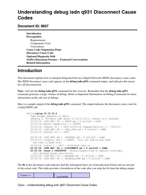
Understanding debug isdn q931 Disconnect Cause CodesDocument ID: 8607IntroductionPrerequisitesRequirementsComponents UsedConventionsCause Code Origination PointDisconnect Cause CodeOptional Diagnostic fieldNetPro Discussion Forums − Featured ConversationsRelated InformationIntroductionThis document explains how to interpret Integrated Services Digital Network (ISDN) disconnect cause codes. The ISDN disconnect cause code appears in the debug isdn q931 command output, and indicates the reason for call disconnection.Note: Activate the debug isdn q931 command for this exercise. Remember that the debug isdn q931 command generates a large volume of debugs. Refer to Important Information on Debug Commands for more information on the safe use of debugs.Here is a sample output of the debug isdn q931 command. The output indicates the disconnect cause code for a failed ISDN call:Calling#ping 10.10.10.2Type escape sequence to abort.Sending 5, 100−byte ICMP Echos to 10.10.10.2, timeout is 2 seconds:20:52:14: ISDN BR0: TX −> SETUP pd = 8 callref = 0x2E20:52:14: Bearer Capability i = 0x889020:52:14: Channel ID i = 0x83 20:52:14: Keypad Facility i = '5551111'20:52:15: ISDN BR0: RX <− CALL_PROC pd = 8 callref = 0xAE20:52:15: Channel ID i = 0x8920:52:16: ISDN BR0: RX <− PROGRESS pd = 8 callref = 0xAE20:52:16: Progress Ind i = 0x8A81 − Call not end−to−end ISDN,may have in−band info20:52:16: Signal i = 0x01 − Ring back tone on20:52:34: ISDN BR0: RX <− DISCONNECT pd = 8 callref = 0xAE20:52:34: Cause i =0x829F08 − Normal,unspecified or Special intercept, call blocked group restriction20:52:34: ISDN BR0: TX −> RELEASE pd = 8 callref = 0x2E20:52:34: ISDN BR0: RX <− RELEASE_COMP pd = 8 callref = 0xAEThe 0x in the disconnect code indicates that the subsequent bytes are in hexadecimal format and are not part of the actual code. This table provides a breakdown of the code after you strip the 0x from the debug output: Cause i =0x829F08Parsed HexBytes829F08Description Cause CodeOriginationPointDisconnectCause CodeOptionalDiagnosticfieldPrerequisitesRequirementsThere are no specific requirements for this document.Components UsedThis document is not restricted to specific software and hardware versions.The information in this document is based on the devices in a specific lab environment. All of the devices in this document started with a cleared (default) configuration. If your network is live, make sure that you understand the potential impact of any command.ConventionsFor more information on document conventions, refer to the Cisco Technical Tips Conventions.Cause Code Origination PointThe first byte (most significant) after 0x indicates the point in the circuit path where the disconnect cause code appears. Consider the sample output in the Introduction section. 82 indicates that the call disconnects from the local telco switch. Here is a list of cause code origination points that help you interpret where the call disconnects from:80 t he router•81 t he private network near the local user (possibly a local private branch exchange [PBX])•82 t he public network near the local user (local telco switch)•83 t he transit network (in the ISDN cloud)•84 t he public network near the remote user (remote telco switch)•85 t he private the network near the remote user (possibly a remote PBX)•87 t he international network•8A a network beyond the internetworking point•Disconnect Cause CodeThe next byte (9F in the sample output) that follows the cause code origination point byte is the Disconnect Cause Code. This byte helps you to troubleshoot the disconnection.Use this table to associate a Disconnect Cause Code (in Hex) and the Cause Description to determine the disconnect reason:Additional InformationHex CodeCause Description80NormalDisconnectThe call disconnects normally.81Unallocated orunassignednumberThe switch receives the ISDN numberin the correct format. However, thenumber does not belong to destinationequipment.82No route tospecifiednetworkThe ISDN exchange receives a requestto route the call through anunrecognized intermediate network.This cause indicates that theequipment receives a request to routethe call through a particular transitnetwork. However, the equipmentdoes not recognize the network.The equipment that sends this causedoes not recognize the transit networkdue to one of these reasons:The transit network does notexist.•The transit network exists, butdoes not serve the equipmentthat sends this cause.•This cause is supported on anetwork−dependent basis.83No route todestination The call routes through an intermediate network that does not serve the destination address.This cause indicates that the called user is not reachable. A user is not reachable when the network used to route the call does not serve the required destination.This cause is supported on a network−dependent basis.84Send specialinformation tone The remote number you dialed is not reachable.Check the number you dial. Verify if you need any prefixes to access the network. For example, you need to dial 9 for outbound calls through a PBX. Contact your telco/PBXadministrator for details.85Misdialled trunkprefix.The remote number you dialed is not reachable.Check the number you dial. Verify if you need any prefixes to access the network. For example, you need to dial 9 for outbound calls through a PBX. Contact your telco/PBX administrator for details.86Channelunacceptable The service quality of the specified channel is insufficient to accept the connection. The call attempt fails because the channel is unusable.If you use a PBX, check the configuration of the PBX. For a PRI, find out how many channels your telco provides.87Call awardedand delivered inestablishedchannelThe user assigns an incoming call thatconnects to an already established callchannel.This cause indicates that the userreceives an incoming call, whichconnects to a channel already in usefor similar calls (for example,packet−mode X.25 virtual calls).88Preemption Your call is blocked. Calls are sometimes blocked if another call has a higher priority than your call. This situation is common with voice calls. Wait and call again later.If you use a PBX (or the remote site to which you connect uses a PBX), check the configuration of the PBX. If the condition persists, contact your telco.89Preemption,circuit reservedfor re−useYour call is blocked. Calls aresometimes blocked if another call hasa higher priority than your call. Thissituation is common with voice calls.Wait and call again later.If either side uses a PBX, check theconfiguration of the PBX. If thecondition persists, contact your telco.90Normal call clearing Normal call clearing occurs. You do not need to perform any action.This cause indicates that the call disconnects because one of the users involved in the call has made a request to clear the call. Under normal situations, the network is not the source of this cause.If the call fails with this Disconnect Cause Code, the call most likely fails at a higher layer protocol such as PPP, authentication or idle timeout related issues. Verify the router configuration. Also, if you have requested a callback, the remote device disconnects the call, generates this code, and then calls you back.91User busy The called system acknowledges the connection request. However, the system cannot accept the call because all B−channels are in use. The user equipment is compatible with the call in this situation.Note: If you have multiple ISDN circuits, the telco can configure them in a "hunt−group", in which calls switch to the next available circuit.92No userresponse The connection fails because the destination does not respond to the call.This cause indicates that a user does not respond to a call establishment message within the prescribed period. The user must respond with either an alert or connect indication according to ITU−T Q.931, when either timer T303 or T310 expires.93No answer fromuser The destination responds to the connection request but fails to complete the connection within the prescribed time. This cause indicates that a user has provided an alert indication, but has not provided a connect indication within a prescribed period. Q.931 procedures do notnecessarily generate this cause. Internal network timers sometimes generate this cause.The problem is at the remote end of the connection.94Subscriberabsent The remote device you attempt to reach is unavailable and is disconnected from the ISDN network. Contact the person responsible for that device.95Call rejected The destination is able to accept the call but rejects the call for an unknown reason.This cause indicates that the equipment that sends this cause does not want to accept this call.Note: The equipment is able to accept the call because the equipment that sends this cause is neither busy nor incompatible. However, the equipment rejects the call.96Numberchanged The ISDN number used to set up the call does not belong to a system.A caller receives this cause when the called party number is no longer assigned. You can optionally include the new called party number in the diagnostic field. If a network does not support this capability, the caller receives cause No. 81, unassigned (unallocated) number.97Redirection tonew destination Your call is routed to a different ISDN number.Check the number you call. Also verify the PBX configuration (if you use PBX).99Exchangerouting error Your call cannot be successfully routed to the remote party.Check the number you call. Also verify the PBX configuration (if you use PBX).9ANon−selected user clearing The destination is able to accept the call. However, the destination rejects the call because the call is not assigned to a user.9B Destination outof order The destination is not reachable because of an interface malfunction. In addition, a signaling message cannot be delivered. This condition can be temporary. However, the condition can last for an extended period in some cases.This cause indicates that a signaling message could not be delivered to the remote user. For example, a physical layer or data link layer fails at the remote user end, and the user equipment is off−line (turned off).9C Invalid numberformat The connection fails because the destination address is in an unrecognizable format, or is incomplete.Verify whether the format of the number is correct. This includes any appropriate digits for a PBX, and long distance.9DFacility rejected The network cannot provide the facility that the user requests.9E Response toSTATUSENQUIRYThe status message appears in directresponse to the receipt of a statusinquiry message.9F Normal,unspecified This message reports the occurrence of a normal event when no standard cause applies. No action is required.A1Circuit out oforder The call cannot go through due to some problem in the ISDN network.A2No channelavailable The connection fails because no appropriate channel is available to take the call.A3Destinationunattainable The destination is not reachable through the Telco network. Contact the Telco.A4Out of order Some part of the network necessary toroute the call is out of order.The destination is not reachablebecause of a network malfunction.The condition can last for an extended period. An immediate attempt to reconnect will probably fail.If you use a long distance carrier, try to use a Presubscribed Inter−exchange Carrier (PIC). For example, you can use a 10−10−xyz carrier. A PIC enables you to verify whether the problem lies with the long distance carrier.A6Network out oforder The destination is not reachable because of a network malfunction. The condition can last for an extended period. An immediate attempt to reconnect will probably fail.If you use a long distance carrier, try to use a Presubscribed Inter−exchange Carrier (PIC). For example, you can use a 10−10−xyz carrier. A PIC enables you to verify whether the problem lies with the long distance carrier.A7Permanentframe modeconnection outof serviceThis message indicates that equipmentfailure probably terminates thepermanent connection.If the problem persists, contact yourtelcoA8Permanentframe modeconnectionoperationalThis message occurs when thepermanent connection is fullyoperational again after a termination.Equipment failure probablyterminated the connection previously.A9Temporaryfailure An error occurs because of a network malfunction. Contact the telco if the problem persists.AA SwitchingequipmentcongestionThe destination is not reachablebecause of a temporary overload onthe network switching equipment. Tryagain later.AB Accessinformationdiscarded The network cannot provide the access information that the user requests.This cause indicates that the network is unable to deliver access information to the remote user. For example,user−to−user information, low layer compatibility, high layer compatibility, or a sub−address as the diagnostic indicates.Note: You have the option to include the particular type of discarded access information in the diagnostic.AC Requestedchannel notavailableThe remote equipment cannot providethe channel that the user requests, dueto an unknown reason. This problemis usually temporary.AF Resourcesunavailable,unspecifiedThe channel or service that the userrequests is unavailable for anunknown reason. This problem isusually temporary.B1Quality ofservice (QoS)unavailableThe network cannot provide thequality of service that the userrequests. This issue can occur due to asubscription problem.This cause reports that the networkcannot provide the QoS as defined inRecommendation X.213. Forexample, this cause code appearswhen the network cannot supportthroughput or transit delay.B2Requestedfacility notsubscribedThe remote equipment supports thesupplementary service by subscriptiononly.This cause indicates that the networkcannot provide the supplementaryservice that the user requests. The userhas probably not completed thenecessary administrative arrangementswith the supporting networks.The ISDN network can also return thiscause code when a user makes a callattempt, but does not enter the SPIDs,or enters the SPIDs incorrectly.Ensure that your SPIDs are correct, orcontact your telco to verify yourSPIDs.Also verify the speed of the outgoingcall that the ISDN network supports(56k or 64k).B4Outgoing calls barred There is some restriction on outgoing calls. The ISDN network does not allow you to make outgoing calls.B5Outgoing callsbarred withinCUG1There is some restriction on outgoingcalls. The ISDN network does notallow you to make outgoing calls.B6Incoming callsbarred The ISDN network does not allow you to receive calls.Contact your telco.B7Incoming callsbarred withinCUG1The ISDN network does not allow youto receive calls.Contact your telco.B9Bearercapability notauthorizedA subscription problem usually causesthis issue.This cause indicates that the userrequests a bearer capability that theequipment implements, but the userdoes not have the authorization to usethe capability.BA Bearercapability notpresentlyavailableThe network normally provides thebearer capability that the userrequests. However, if the capability isunavailable currently, this causeappears. A temporary networkproblem or a subscription problem cancause this issue.If the incoming call is Analog(modem call), verify whether youhave an ISDN incomingvoice−modem under the PRI or BRIphysical interface.BF Service/optionnot available,unspecifiedThe network or remote equipmentcannot provide the service option thatthe user requests, due to anunspecified reason. A subscriptionproblem can cause this issue.C1Bearercapability notimplementedThe network cannot provide the bearercapability that the user requests.Contact the telco to troubleshootfurther.C2Channel typenot implemented The network or the destination equipment does not support the channel type that the user requests.C5Requestedfacility notimplementedThe remote equipment does notsupport the supplementary service thatthe user requests.C6Only restricteddigital infobearer capabilityavailableThe network cannot provideunrestricted digital information bearercapability.This cause indicates that a devicerequests an unrestricted bearer service.However, the equipment only supportsthe restricted version of the bearercapability.CF Service/optionnotimplemented,unspecifiedThe network or remote equipmentcannot provide the service option thatthe user requests, due to anunspecified reason. A subscriptionproblem can cause this issue.D1Invalid callreference value The remote equipment receives a call with a call reference that is not currently in use on the user−network interface.D2Identifiedchannel does notexistThe user requests the receivingequipment to use a channel that is notactivate on the interface for calls.This cause indicates that theequipment receives a request to use aninactive channel on the interface for acall. For example, if a user subscribesto those channels on a primary rateinterface numbered from 1 to 12 andthe user equipment or the networkattempts to assign a call to channels13 through 23, this cause codeappears.D3Suspended callexists, but call iddoes notThe network receives a call resumerequest. The call resume requestcontains a Call Identify (ID)information element that indicates thecall ID that represents a suspendedcall.This cause indicates that a userattempts to resume a call with a callID which differs from the ID in usefor any currently suspended call(s).D4Call id in use The network receives a call resumerequest. The call resume requestcontains a Call ID informationelement that indicates the resume request is for a suspended call.This cause indicates that the network receives a call suspend request. The call suspend request contains a call ID (including the null call ID). This ID is already in use for a suspended call within the domain of interfaces over which the call can be resumed.D5No callsuspended The network receives a call resume request when there is no suspended call pending. You can resolve this transient error through successive call retries.This cause code indicates that the network receives a call resume request. The call resume request contains a call ID information element that currently does not indicate any suspended call within the domain interfaces over which calls can be resumed.D6Call withrequested call idhas been clearedThis cause indicates that the networkreceives a call resume request. Thecall resume request contains a call IDinformation element that originallyindicated a suspended call. However,either a network timeout or a remoteuser clears the suspended call.D7User notmember ofCUG1Your call does not go through,probably due to one of these reasons:You dial an incorrect ISDNnumber.•You request a service that youare not authorized to use (youhave not subscribed to thisservice).•The remote device is notauthorized to use a servicethat you use.•Check the number you call. If theproblem persists, contact your telco.D8Incompatibledestination This cause indicates an attempt to connect to non−ISDN equipment. For example, an analog line.This cause indicates that the equipment receives a request to establish a call that has a low layer compatibility, high layer compatibility, or other compatibility attributes (for example, data rate) that the equipment cannot accommodate. This code often appears when the calling device dials the wrong number, and reaches a non−ISDN device. Therefore, ensure that you dial the correct number.This cause can also occur when a a data call is made to a voice number, or a voice call is made to a number that only supports data. If the number is correct, check whether the telco has configured their switch incorrectly.DA Non−existentCUG1Your call does not go through, probably due to one of these reasons: You dial an incorrect ISDNnumber.•You request a service that youare not authorized to use (youhave not subscribed to thisservice).•The remote device is notauthorized to use a servicethat you use.•Check the number you dial. If the problem persists, contact your telco.DB Invalid transitnetworkselectionThe device requests the ISDNexchange to route the call through anunrecognized intermediate network.This cause indicates that the ISDNexchange receives a transit networkidentification of an incorrect format.Annex C of ITU−T Q.931 providesthis definition.DF Invalid message,unspecified An invalid message appears with no standard cause. This problem usually occurs due to a D−channel error. If the error occurs systematically, report the error to your ISDN service provider.E0Mandatory IE missing The receiving equipment receives a message that does not include one of the mandatory information elements.This cause indicates that the equipment receives a message that does not contain an information element that is necessary for the equipment to process the message.This problem occurs due to aD−channel error. Ensure that you configure the switch type correctly. Upgrade your Cisco IOS® Software on the router to solve this issue. If the error occurs systematically, report the error to your ISDN service provider.E1Message typenot implemented The receiving equipment receives an unrecognized message, because either the message type is invalid, or the equipment does not support the message type. A problem with the remote configuration or with the local D−channel causes this issue.E2Message notcompatible withcall state or notimplementedThe remote equipment receives aninvalid message with no standardcause.This cause indicates that theequipment receives a message that isnot permissible in the call stateaccording to the procedures. Thiscause can also indicate that theequipment receives a STATUSmessage to indicate an incompatiblecall state.The issue occurs due to a D−channelerror. If the error recurs, report theerror to your ISDN service provider.E3IE notimplemented The remote equipment receives a message that includes information elements that the equipment cannot recognize.This cause indicates that the equipment receives a message that includes information elements that the device cannot recognize. This problem can occur when the equipment doesnot define or implement the information element identifier. However, the message does not need to contain the information element in order for the equipment to process the message.This issue occurs due to a D−channel error. If the error recurs, report the error to your ISDN service provider.E4The remote equipment receives a message that includes invalid information in the information element.This cause indicates that the equipment receives an information element that is implemented, but one or more of the fields in the information element are coded differently.This issue occurs due to a D−channel error.E5Message notcompatible withcall stateThe remote equipment receives anexpected message that does notcorrespond to the current state of theconnection.This issue occurs due to a D−channelerror.E6Recovery ontime expiry Your call does not go through, probably because an error occurs. For example, a state synchronization error. Wait and try again later. If the problem persists, contact your ISDN service provider.E7Parameter notimplemented Your call does not go through because the ISDN network does not support a service you need to use.Contact your ISDN service provider.EF Protocol error,unspecified This cause indicates an unspecified D−channel error with no other standard cause.FF Interworking,unspecified This cause indicates that an event occurs, but the network does not provide causes for the action. Theprecise problem is unknown.??Unknown CauseThe cause value is unknown.value1 CUG: Closed User Group is a facility in X.25 and ISDN networks that allows a called number to be available only to a limited number of other users (in a virtual private network). Contact your telco for more information.Optional Diagnostic fieldThe last two hexadecimal digits (08 in the example) are optional. You do not commonly use these digits for diagnostic purposes. However, you can sometimes use this byte to furnish additional information for the Disconnect Cause Code. The debug isdn q931 output can sometimes contain these digits.NetPro Discussion Forums − Featured ConversationsNetworking Professionals Connection is a forum for networking professionals to share questions, suggestions, and information about networking solutions, products, and technologies. The featured links are some of the most recent conversations available in this technology.NetPro Discussion Forums − Featured Conversations for AccessNetwork Infrastructure: Remote AccessRelated InformationUsing the show isdn status Command for BRI Troubleshooting••Troubleshooting ISDN BRI Layer 3 using the debug isdn q931 Command•ISDN Debug Command ReferenceISDN Switch Types, Codes, and Values••Dialup Technology: Troubleshooting Techniques•Dialup Technology: Overviews and Explanations•Mica Modem Disconnect Reasons•Technical Support & Documentation − Cisco SystemsAll contents are Copyright © 2006−2007 Cisco Systems, Inc. All rights reserved. Important Notices and Privacy Statement. Updated: Jul 09, 2007Document ID: 8607。
专业英语(电子与信息工程类)翻译
1.As data networks advanced…also grew more complex.由于数据网络从面向终端的系统向分组交换、计算机与计算机连接的方向发展, 执行网络功能所必需的协议也变得愈来愈复杂。
2.An additional bit called a parity bit…during transmission.在每个字符的后面有时还包括一个称为奇偶校验位的附加位, 它们测试数据位在传输过程中是否被意外改变。
3.As already stated, with…downlink(FDD paired bands).如前所述, 在非对称通信量应用中, TD-SCDMA利用可用频谱的效率比其他3G标准高, 因为它在只利用一个频带(TDD单一频带)而不是两个独立的频带(FDD成对频带)进行上行与下行通信。
4.Although often simpler to implement, …digital modulation.虽然光纤系统的模拟调制易于实现, 但其效率较低, 且要求在接收端有比数字调制高得多的信噪比。
5.At present, the bandwidth…electronics ()is possible.目前传输100km的几吉赫兹的调制信号和传输300km的几百兆赫兹的调制信号都是可能的, 因此光纤系统的可用带宽并没有得到充分利用。
6.Both TD-SCDMA deployments-TSD…unpaired bands awarded.TD-SCDMA的两种部署——TSM和TDDCLR的数据速率、频谱利用率、覆盖率、移动性和可靠性等性能是一样的, 并基本上为所有取得非成对TDD频段牌照的运营商所采用。
7.Crossbar sw itching was carried…selection for all calls.纵横制交换由一个称为标志器的特定电路控制, 标志器提供整个号码的公共控制并选择所有呼叫的路由。
0625_w02_qp_3

FOR EXAMINER’S USE
1 2 3 4 5 6 7 8 9 10 TOTAL
This question paper consists of 14 printed pages and 2 blank pages.
SP (NF/KS) S23400/3 © CIE 2002
[Turn over
density of rock = .............................. [2]
0625/3/O/N/02
5 3 A thermocouple is used to measure the temperature of the inner wall of a pottery kiln. (a) In the space below, draw a labelled diagram of a thermocouple that could be used for this purpose. [2]
Centre Number Candidate Name
w w w
Candidate Number
e tr .X
m
ap eP s er om .c
International General Certificate of Secondary Education CAMBRIDGE INTERNATIONAL EXAMINATIONS
(b) Describe how the volume of the rock could be found. .......................................................................................................................................... .......................................................................................................................................... ......................................................................................................................................[2] (c) The mass of the rock is 88 g and its volume is 24 cm3. Calculate the density of the rock.
海运术语

abbreviations0-93G3rd Generation Networks3PL3rd Party Logistics4PL4th Party Logistics4SC4-High Straddle Carrier5-S Seiri, Seiton, Seiso, Seiketsu, ShitsukeAABC ABC ClassificationAGVs Automated Guided VehiclesAI Artificial IntelligenceAMPS Administrative Monetary Penalty SystemAMS Automated Manifest SystemANERA Asia North America Eastbound Rate Agreement A.P.All purposesAPEC Asia-Pacific Economic CooperationAPI Application Programming InterfaceASME American Society of Mechanical Engineers ASN Advanced Shipping NoticeASP Active Sever PageAS/RS Automated Storage and Retrieval Systema.t.s.All time savedAWB Air WaybillBB2B Business to BusinessB2C Business to CustomerBAF Bunker Adjustment FactorB/B Break BulkBCC Blind Carbon CopyBCO Beneficial Cargo OwnerBIMCO The Baltic and International Maritime Council B/L Bill of LadingBPO Business Process OutsourcingBSC Balanced ScorecardBSP British Standard Pipe TreadCCAF Currency Adjustment FactorCBM Cubic MetreCBO Community Based OrganizationCC Carbon CopyCCR Commodity Classification RatesCDMA Code Division Multiple AddressCEP Courier, Express, ParcelCEPA Closer Economic Partnership Arrangement C&F Cost and FreightCF Collapsible Flat RackCFM Cubic Feet per MinuteCFR Cost and FreightCFS Container Freight StationCGI Common Gateway InterfaceCIF Cost, Insurance and FreightCILT The Chartered Institute of Logistics andTransportCIM The Chartered Institute of MarketingCIP Carriage and Insurance Paid ToCIS Commonwealth of Independent States CKD Completely Knocked DownCLM The Council of Logistics ManagementCLP Container Load PlanCNOOC China National Offshore Oil Corp.C/O Certificate of OriginCOA Contract of AffreightmentC.O.C.Carrier's Own ContainerC.O.D.Cash On DeliveryCOFC Container-on-flatcarCOGS Cost of Goods SoldCon-Ro Container-Roll ShipCOP Custom of the PortCOSCO China Ocean Shipping CompanyCOSL China Oilfield Services LimitedC/P Charter PartyCPFR Collaborative Planning Forecasting andReplenishmentCPT Carriage Paid ToCQD Customary Quick DispatchCRM Customer Relationship ManagementCRP Continuous Replenishment ProgramCSC International Convention for Safe ContainerCSF Critical Success FactorCSI Container Securtiy IntiativeCSP Commerce Service ProvidersCY Container YardDD/A Document Against Acceptance DAF Delivered at FrontierDC Distribution CentreD1/2D Demurrage Half DispatchDDC Destination Delivery ChargeDDF Documentation Fee – Destination DDP Delivered Duty PaidDDU Delivered Duty UnpaidDEQ Delivered Ex-QuayDES Delivered Ex-Shipd.f.Dead FreightDFZ Duty Free ZoneD.G.Dangerous GoodsDHC Handling Charge – Destination DNS Domain Name SystemD/O Delivery OrderD.O.P Dropping Outward PilotDOS Disk Operating SystemD/P Document Against PaymentDPA Transport Arbitrary – Destination DPP Damage Protection PlanD/R Dock ReceiptDRP Distribution Resources Planning DWCT Deadweight Cargo TonnageDWT Deadweight Tonnage (All Told)EECR Efficient Customer Response ECSI Export Cargo Shipping Instruction EDI Electronic Data InterchangeEH&S Environment Health & SafetyEIR Equipment Interchange Receipt E.I.U.Even If UsedE.&O.E.Errors and Omissions Excepted EOQ Economic Order QuantityEPQ Economic Production Quantity ERM Enterprise Resources Management ERP Enterprise Resources Planning ETA Estimated Time of ArrivalETD Estimated Time of DepartureETR Estimated Time of ReadinessETS Estimated Time of SailingEXW Ex-WorksFFAF Fuel Adjustment FactorFAK Freight All KindsFAQ Frequently Asked QuestionFAS Free Alongside ShipFB/L FIATA Combined Transport Bill of Lading FBO Faith Based OrganisationFCA Free CarrierFCL Full Container LoadFCR Forwarder's Cargo ReceiptFEFC Far East Freight ConferenceFEU Forty Feet Equivalent UnitF.H.E.X.Fridays and holidays excludedF.I.Free InFIATA International Federation of Forwarding Agent AssociationsFIBC Flexible Intermediate Bulk ContainerFIFO First-in, First-outF.I.O.Free In and OutFIOST Free In, Out, Stowed & TrimmedFIS Fixed-Interval SystemFMC Federal Maritime CommissionFMCG Fast Moving Consumer GoodsF.O.Free OutFOA Fire Defence Agency (Japanese)FOB Free On BoardF.O.R.Free On RailF.O.T.Free On TruckF.P.A.Free of Paticular AverageFQS Fixed-Quantity SystemFR Flat Rack ContainerFRC Fuel Recovery ChargeFSDC Full-Service Distribution CompanyFT Freight TonFTP File Transfer ProtocolFTZ Free Trade ZonesGGATT General Agreement on Tariffs and Trade GCC Gas Carrier CodeGCR General Cargo RatesGDP Gross Domestic ProductGIF Graphics Interchange FormatGMDSS Global Maritime Distree and Safety System GP General Purpose ContainerGPRS General Packet Radio ServiceGPS Global Positioning SystemGRI General Rate IncreaseGRT Gross Registered TonnageGSA General Sales AgentGSC Global Supply ChainGSM Global System for Mobile CommunicationsGVW Gross Vehicle WeightsGWT Gross WeightHHAFFA Hong Kong Association of Freight Forwarding and Logistics Ltd.HAWB House Air WaybillH.F.O.Heavy Fuel OilH/H Half Height ContainerHKIM Hong Kong Institute of MarketingHSCodesHarmonized System of CodesHTML Hypertext Mark-up LanguageHTTP Hypertext Transfer ProtocolII.A.Im AuftragIADA Intra Asia Discussion AgreementIAF Inflation Adjustment FactorI.A.RatesIndependent Action RatesIATA International Air Transport AssociationIBC Intermediate Bulk ContainerICAO International Civil Aviation OrganizationICC International Chamber of CommerceICD Inland Container DepotICP Internet Content ProviderICT Information and Communications TechnologyIEEE the Institute of Electronic and Electrical EngineeringIICL Institute of International Container Lessors IMDG International Maritime Dangerous Goods Code IMF International Monetary FundIMO International Maritime OrganizationIncotermsInternational Commercial TermsIP Internet ProtocolIPI Interior Point IntermodalIPO Initial Public OfferingIRA Informal Rate AgreementISAPI Internet Server Application ProgrammingInterfaceISDN Integrated Server Digital NetworkISO International Standard OrganizationISP Internet Service ProviderISPS International Ship and Port Facility Security ITF International Transport Workers' Federation IWL Institute Warranty LimitsJJIT Just In TimeKKbps Kilobits per secondKPI Key Performance IndicatorKSF Key Success FactorK/T Kilo TonsLLAN Local Area NetworkingLASH Ligther Aboard ShipLAYCAN Laydays/Cancelling (Dates)L/C Letter of CreditLCL Less than a Container LoadL/G Letter of GuaranteeL.I.Liner InwardLIFO Liner In Free OutLILO Last-In, Last-OutL.I.O.Liner In and OutL/L Loading ListL.L.M.C Limitation of Liability for Maritime Claims LMX Leader-Member ExchangeLNG Liquefied Natural GasL.O.A.Lenght OverallLo-Lo Lift-on Lift-off ShipLPG Liquefied Petroleum GasLSD Landing, Storage and DeliveryLT Lead TimeLTL Less-Than-TruckloadMMAWB Master Air WaybillMB MegabyteMBO Management By ObjectiveMbps Millions of Bits Per SecondMIS Management Information SystemMLB Mainland BridgeMLO Main Line OperatorsMMS Multimedia Messaging ServicesM/N Marks and NumbersMNC Multinational Corporationmol.More or LessMOLCHMore or Less in Character's OptionOPMOLOO More or Less in Owner's OptionMPEG Motion Picture Experts GroupMPS Master Production ScheduleMQC Minimum Quantity CommitmentM/R Mate RateMRP Material Requirements PlanningMRP II Manufacturing Resource PlanningM/S Motor ShipMSDS Material Safety Data SheetMT Metric TonMTO Multimode Transport OperatorNN/A Not Applicable/Not AvailableNAFTA North America Free Trade AgreementNAP Network Access PointNCV No Customs ValuationNEC Not Elsewhere ClassifiedNGO Non-Governmental OrganizationN.O.E.Not Otherwise EnumeratedNOI Not Otherwise IndexedNOIBN Not Otherwise Indexed by NameNOR Notice of ReadinessN.O.S.Not Otherwise SpecifiedNPO Non Profit OrganizationNRT Net Registered TonnageNVD No Value DeclaredNVOCC Non Vessel Operating Common Carrier NWT Net WeightOOCP Overland Common PointOD Organization DevelopmentODC Odd Dimension CargoesODF Documentaion Free - OriginOECD Organization for Economic Cooperation and DevelopmentOEM Original Equipment ManufacturerO/H Over HeightOHC Handling Charge - OriginOJT On-the-Job TrainingOMC Occupational Market ConditionOPM Other People's MoneyORC Origin Receiving ChargeO/S Open Side ContainerOS&D Over, Short and DamagedOSHA Occupational Safety & Health ActOT Open Top ContainerO/T Over TimeOTROff-the-Road TyresTyresO/W Over WidthOWS Overweight SurchargePP2P Path to ProfitP2P Peer-to-PeerPAI Peformance Appraisal InterviewPAQ Position Analysis QuestionairePCD Pitch Circle DiameterPCS Port Congestion SurchargePDA Personal Digital AssistantPDF Portable Document FormatPDPR Per Day Pro RataPENAVIChina Ocean Shipping CompanyCOP.F.T.Per Freight TonP. & I.Protection and Indemnity Club (Association) ClubPKI Public Key InfrastructurePOD Port of DischargePOL Port of LoadingPOP Point of PresencePOS Point of SaleP.P.Per ProeurationemPPP Point-to-Point ProtocolPRD Pearl River DeltaPS Port SurchargePSS Peak Season SurchargePSTN Public Switched Telephone NetworkPTO Please Turn OverleafPWS Personal Web ServerQQDII Qualified Domestic Institutional Investors QFII Qualified Foreign Institutional InvestorsQR Quick ResponseRRAM Random Access MemoryREIT Real Estate Investment TrustRF Reefer ContainerRFID Radio Frequency IdentificationRFP Request for ProposalRFQ Request for QuotationRFRC Rail Fuel Recovery ChargeRMB RenminbiRMG Rail Mounted GantryROA Return on AssetsR.O.B.Remaining on BoardROI Return on InvestmentRo-Ro Roll-on Roll-off ShipRRS Rate Restoration SurchargeR/T Revenue TonsR.T.W.Round the World ServiceRVNX Released Value Not ExceedingSS.A.Safe GroundSAN Storage Area NetworkS.B.Safe BerthSBT Segregated Ballast TankS/C Service ContractSCM Supply Chain ManagementSCQ Special Commodity QuotationSCR Specific Commodity RatesS.D.Single Deck ShipSED Shipper's Export DeclarationSER Carrier Security ChargeSET Secure Electronic TransactionS.G.Specific GravitySHEX Saturday and Holidays Excluded SHINC Saturday and Holidays Included SIM.SUSimilar SubstituteB.SKU Stock Keeping UnitSLA Services Level AgreementSME Small and Medium-size Enterprises SMS Short Message ServicesSMTP Simple Mail Transport Protocol SNMP Simple Network Management Protocol S/O Shipping OrderS.O.C.Shipper's Own ContainerS.P.Safe PortSPC Statistical Process ControlSPIM Single Period Inventory ModelsSQL Structure Query LanguageSS Safety StockS/S SteamshipS.S.H.E. X.Saturdays, Sundays and Holidays ExcludedS.S.H.I.N.C.Saturdays, Sundays and Holidays Included SSL Secure Socket LayerS.T.C.Said To ContainSTCC Standard Transportation Commodity CodeTTACA Transatlantic Conference AgreementTBN To Be NominatedTCP Transmission Control ProtocolTDW Total DeadweightTEU Twenty-foot Equivalent UnitT.H.C.Terminal Handling ChargeTMS Transportation Management SystemTOFC Trailer-On-FlatcarTPC Tones Per CentimeterTPD Tones Per DayTPI Tones Per InchTQC Total Quality ControlTQM Total Quality ManagementT.R.S.Terminal Receiving StationTSA Transpacific Stabilization AgreementTSR Trans Siberian RailwayTT Telegraphic TransferTVC Time Volume ContractTWRA Transpacific Westbound Rate AgreementUUBC Universal Bulk CarrierUCP Uniform Customs and Practice for Documentary CreditsUHF Ultra High frequencyULCC Ultra Large Crude CarrierULD Unit Load DeviceUNCTAD United Nations Conference of Trade andDevelopmentURL Uniform Resource LocatorUU Unless UsedVVAN Value-Added NetworksV.A.T.Value Added TaxVHF Very High Frequencyly (Used in Tariffs to Specify Commodities VLCC Very Large Crude CarrierVMI Vendor Managed InventoryVOC Vessel Operating CarrierV.O.W.Vehicle On WheelVPN Virtual Private NetworkV.S.A.Vessel Sharing AgreementVSL VesselWWAP Wireless Appreciation ProtocolWCS Wireless Communications ServiceWDEX Warehouse Withdrawal for Transportation Immediate ExportationWDT Warehouse Withdrawal for TransportationWDT&E Warehouse WithdrawalforTransportationExportationW.E.F.With Effect FromW.I.B.O. N.Whether In Berth Or NotW.I.F.P.O.N.Whether In Free Pratique Or NotWI-FI Wireless FidelityWIP Work in ProcessW.I.P.O.N.Whether In Port Or NotW/M Weight or MeasurementWMS Warehouse Management SystemWPA With Paticular AverageW.P.Weather PermittingW.R.War RisksWTO World Trade OrganizationW.T.S.Working Time SavedW.W.Warehouse WarrantWWD Weather Working DaysW.W.R.C.D.Whe n Wh ere Ready on Completion of Discharge WWW World Wide WebXXML Extensible Mark-up LanguageYYAS Yen Appreciate Surcharge第三代網路第三方物流第四方物流集裝箱高跨車吊具常組織、常整頓、常清潔、常規範、常自律ABC分類化自動導引車人工智能行政罰款制度海關自動艙單系統亞洲北美東向運協會全部裝卸時間亞太經濟合作組織程式設定介面機械工程師美洲協會事前出貨通知單動態伺服端網員自動化存儲和修復系統操作節省的全部時間空運提單企業與企業之間的交易企業與客戶之間的交易燃油附加費散件雜貨密件抄送貨物擁有者權益波羅的海國際海運公會海運提單企業外判程序平衡記分卡英國標準的管子踩踏幣值附加費立方米社區性組織抄送等價貨物運價分發(部門)若干位址編碼-更緊密經貿關系的安排成本和運費折疊式板架集裝箱每分鐘的立方尺成本和運費集裝箱貨物集散站共同閘道介面成本和運費兼付保險費英國特許物流運輸學會英國特許市務學會兼付指定運費及保險費獨立國家聯合體全拆裝物流管理學會集裝箱/裝載計劃表中國海洋石油總公司產地來源證包運合同船東提供集裝箱交貨付現集裝箱輸送銷貨成本集裝箱/滾裝兩用船港口慣例中國遠洋運輸公司中海油田服務股份有限公司租船合同(租約)預報和補充合作計劃兼付指定運費習慣快速裝運客戶關係管理連續補充庫存計劃對安全容器的國際規定-商業服務提供商集裝箱堆場承兌交單貨交邊境配送中心速遣費為滯期費的一半目的地提貨費目的地文件費貨交入口國家連稅貨交入口國家倉庫貨交指定港口倉庫貨交指定港口船上虧艙費貨交指定港口倉庫危險品貨物目的地操作費網絡領域名字系統出貨單引航員下船時磁盤作業系統付款交單目的地運輸附加費集裝箱損壤保險場站收據分發資源計劃淨載重吨位總載重吨位(量)有效回應顧客的準則-電子資訊傳遞職業環境健康安全集裝箱設備交接單即使使用錯誤和遺漏不在此限經濟訂購量經濟生產批量企業資源管理企業資源計劃預定扺港時間預定離港時間預計準備就緒時間到戶取貨燃料附加費同一費率常見問題船邊交貨國際運輸商協會聯運提單宗教組織貨交貨運商人整箱集裝貨運承運人領貨單遠東歐州運費公會40英呎標準雜裝箱計算單位星期五和節假日除外船方負責裝船費用國際運輸商協-貨物先進倉和先出倉的安排船方不負擔裝卸費船方不負責裝船卸船理艙及平艙費用定期訂貨方式美國聯邦海事委員會快速銷售消費品船方不負責卸船費用防禦代辦處離岸價格火車上交貨貨車上交貨-定量訂貨方式平板集裝箱恢復燃料費全方位物流服務公司運費吨檔案傳輸協定自由貿易區關與貿易總協定-普通貨物運價國民生產總值圖形學交換版式-多用途集裝箱全球衛星定位系統全部費率調高注冊(容積)總吨總推廣代理全球供應鏈全球系統之機動通信-毛重香港貨運物流業協會有限公司代理空運提單重油半高集裝箱香港市務學會-超文本記號超文本傳送-亞洲集裝箱運輸研討協定通貨膨脹調整系數獨立等級價格國際航空運輸協會中型液體集裝箱國際民用航空組織國際商會?陸集裝箱聯網內容供應商資訊和通訊技術電子和電的工程學院國際集裝箱出租商學會國際危險的商品代碼-國際海事組織國際貿易術語國際網路議定書經美國西岸入內陸運輸首次上市集資項目非正式運價協定國際網路伺服器應用式設計介面數位式多功能公眾通信網路國際標準化組織網絡供應商國際船舶與港口保安設施規則國際運輸工人聯合會(倫敦保險人)協會保証航行範圍運送及時千分之一秒關鍵績效指標成功因素公噸本區域網絡集裝箱子母船-信用證併箱散貨保函入口航線運費不包括卸貨費貨物後進倉和後出倉的安排船方負責裝卸費,但不包碼頭費裝貨清單海事索賠任限制領導-成員交換理論液化天然氣全長吊裝船液化石油汽卸貨、倉儲和送貨費訂貨到交貨的時間散貨拼車空運提單百萬位元目標管理數百萬位分之一秒管理資訊系統大陸橋運輸模式遠洋船公司多型通訊聯繫服務嘜頭-增减承租人有增選擇權船東有增選擇權活動圖片小組專家總生產日程表最小數量承諾-材料需要計劃-輪船材料安全資料表公吨聯運商不適用/無資料北美自由貿易協定網路途徑點無聲明價值-非政府組織除非另有列名--船舶準備就緒通知書除非另有指定非營利組織注冊(容積)淨吨不要求聲明價值無船舶公共承運商-內陸公共交貨點組織發展特殊尺寸貨物來源地文件費-原產商超出正常高度來源地操作費在職培訓-籌集資金始發港付加費開邊集裝箱超, 欠及破損 (指收貨與提單不一致的三種情況) -開頂集裝箱加班時間-超出正常闊度超重附加費對得益的路徑同儕網路運算---港口擠塞附加費電子手賬便攜式文件版式-中國外輸代理公司(外代)每運費吨船東保賠協會公開鑰匙基礎卸貨港裝貨港存在的點--點對點的草案泛珠三角州港口附加費季節附加費公開轉換電話網路請閱後頁私人伺服器國內機構投資者赴海外投資資格認定制度國外機構投資者到內地投資資格認定制度快速反應隨機途徑記憶(存儲器)領匯房地產投資信託基金冷藏集裝箱無線射頻識別技術書面建議要求書面報價要求軌道燃料恢復費用人民幣台軌道式龍門吊資產回報船上所有投資回報滾裝船比率修復附加費計費噸全球性服務-安全擱淺網路存儲安全泊位分隔壓載水艙貨量簽訂合同鏈鎖供給管理特種商品報價特種貨物運價單層甲板船-船東保安費用安全電子交易比重--相似替換船儲備保持的單位服務等級協議中、小型企業短訊服務簡單郵件運輸草案簡單網路管理草案裝船單付貨人所屬集箱安全港口統計製程管制單一週期的存貨模式架構疑問語安全庫存-星期六、日和節假日除外星期六、日和節假日包括在內付款加密法據報內裝-跨大西洋公會協定指定船舶傳輸控制草案總載重量20英呎標準集裝箱計算單位碼頭操作費運輸管理系統集裝箱車架輸送每厘米吃水吨數每天裝卸吨數每英寸吃水吨數全面品質控制全面品質管理碼頭收貨站跨太平洋穩定協議西伯利亞大鐵路電匯時間貨量合同泛太平洋西向運費協會通用散裝貨船跟單信用證統一慣例和實務特高頻50萬噸油輸成組器聯合國貿發會議網址-增值網增值稅甚高頻-20萬噸油輪供應商的存貨管理系統船舶承運商可駕駛的車輛虛疑網路船舶共用協議輪船無線應(運)用草案無線通信服務---自生效無論靠泊與否無論是否通過檢驗無線相容認證未完工的產品不論是否在港內重量/體積倉庫管理系統-天氣允許兵險-節省的裝卸時間--何時何處還船全球資訊網(發源地-歐洲量子物理實驗室)可延長的記號語言日圓調整費。
H3C ISDN命令
命令手册接入分册 ISDN 目录目录第1章 ISDN配置命令.............................................................................................................1-11.1 ISDN配置命令....................................................................................................................1-11.1.1 dialer isdn-leased (ISDN BRI interface view).....................................................1-11.1.2 display isdn active-channel.....................................................................................1-21.1.3 display isdn call-info................................................................................................1-31.1.4 display isdn call-record............................................................................................1-51.1.5 display isdn parameters..........................................................................................1-61.1.6 display isdn spid......................................................................................................1-81.1.7 isdn bch-local-manage............................................................................................1-91.1.8 isdn bch-select-way...............................................................................................1-101.1.9 isdn caller-number.................................................................................................1-111.1.10 isdn calling...........................................................................................................1-121.1.11 isdn check-called-number...................................................................................1-121.1.12 isdn check-time...................................................................................................1-131.1.13 isdn crlength........................................................................................................1-141.1.14 isdn ignore connect-ack......................................................................................1-151.1.15 isdn ignore hlc.....................................................................................................1-161.1.16 isdn ignore llc......................................................................................................1-171.1.17 isdn ignore sending-complete.............................................................................1-171.1.18 isdn l3-timer.........................................................................................................1-191.1.19 isdn link-mode.....................................................................................................1-201.1.20 isdn number-property..........................................................................................1-201.1.21 isdn overlap-sending...........................................................................................1-251.1.22 isdn pri-slipwnd-size............................................................................................1-261.1.23 isdn protocol-mode..............................................................................................1-271.1.24 isdn protocol-type................................................................................................1-281.1.25 isdn q921-permanent..........................................................................................1-291.1.26 isdn send-restart.................................................................................................1-291.1.27 isdn spid auto_trigger..........................................................................................1-301.1.28 isdn spid nit.........................................................................................................1-311.1.29 isdn spid timer.....................................................................................................1-321.1.30 isdn spid service..................................................................................................1-321.1.31 isdn spid resend..................................................................................................1-331.1.32 isdn spid1............................................................................................................1-341.1.33 isdn spid2............................................................................................................1-351.1.34 isdn statistics.......................................................................................................1-361.1.35 isdn two-tei..........................................................................................................1-371.1.36 isdn message-conversion progress-to-alerting enable.......................................1-381.1.37 permanent-active................................................................................................1-391.1.38 power-source.......................................................................................................1-401.1.39 shutdown.............................................................................................................1-41本文中标有“请以实际情况为准”的特性描述,表示各型号对于此特性的支持情况可能不同,本节将对此进行说明。
细说移动通信中的新技术(A new technology in mobile communicati
细说移动通信中的新技术(A new technology in mobilecommunication)As people's living space, activity space and participation areas continue to expand, the functional requirements of mobile phones, not only dialogue and communication, there are many other functions. Moreover, the existing communication system there exist many unsatisfactory places, such as system capacity, voice distortion, dropped on line, power radiation and slow data transmission, the existing communication technology alone is not enough to meet the new demands of communication people. So in this case, we must have new communication technology to ensure, so that a variety of emerging communication technology came into being, below is some of the 3G communications may be used in the new technology.1. Channel coding and decoding technologyThis technique may be used in the DS-CDMA communication standard, in which channel coding and decoding is mainly to reduce the signal transmission power and solve the inevitable fading problem of the signal in the wireless communication environment. The use of codec technology combined with interleaving can improve the BER performance, compared with no encoding, convolutional codes can improve the bit error rate is two orders of magnitude reached 10-3~10-4, and the DS-CDMA communication system using Turbo code error rate can be increased to 10-6. DS-CDMA candidate channel coding techniques include Reed-Solomon and Turbo codes, and Turbo codes can be used as 3G data encoding and decoding technology because the encoding and decoding performance can approach the Shannonlimit. Convolutional codes are mainly used for low data rate speech and signaling.2. Smart antenna technologyIn the development of mobile communication technology, smart antenna has become one of the most active fields. In recent years, almost all advanced mobile communication systems will use this technology. The advantage of smart antenna technology to mobile communication system is difficult to replace by any technology at present. Smart antenna technology has become one of the most attractive technologies in mobile communications. Smart antenna technology uses adaptive beamforming technology to improve the user's direction of arrival gain, while using the zero of the pattern to reduce the interference of high-power users on the space. Its main difficulties lie in the inconsistency of multi-channel and correction technology, the complexity of RAKE receiver combining baseband processing, and the inconsistency of the uplink and downlink direction of arrival caused by FDD technology.3, multi user detection technologyIn the third generation mobile communication system, WCDMA system is a typical example of application of multi user detection technology. As one of the key technologies in WCDMA system, multi user detection technology can make the system achieve good performance in high speed channel environment. Multiuser detection technology improves system performance and increases system capacity by removing cell interference. Multiuser detection technology can effectively mitigate thefar / near effects in DSSS WCDMA systems. The difficulty is the high complexity of baseband processing.4 、 soft handover technologyThe largest mobile phone users opinions on the network is often lost, now people not only during the call by its bitter, but some people worry that if the future network fax support, will not be dropped due to the problems of wireless fax into the water". This is because the mobile phone is switched more when the "hard switching", from a base station coverage area into another base station coverage area to break the original base station and the base station to contact, and then look for new entrants into the coverage area, which is commonly referred to as "first off", of course the off time difference of only a few hundred milliseconds, under normal circumstances, people can not feel, but once the mobile phone for entering the shield area or channel busy and unable to contact with a new base station, it will fall; CDMA technology is used in "soft switching", in the handover, mobile phone and continue to fall and the original base station the contact and contact with the new base station when the mobile phone has been confirmed and the new base station, the original base station and the link is broken, "and then off, dropping may be almost nothing.5, PHS TechnologyThe English name of PHS is Personal Handyphone System,Chinese meaning is personal mobile phone system, the network system is developed by the Japan Telegraph Company, it usesdigital transmission mode, combined with advanced radio access technology and intelligent digital network capabilities. PHS uses low power to transmit radio wave signals, so it covers a smaller area and is more suitable for urban areas, and relatively low rates. PHS provides complete communications services, the integrity of the data transmission ability to support wireless multimedia communication, secondly, PHS also offers a variety of Internet interface, such as: radio access, telephone lines, fiber optic cable, and because of its base design is very light, can support such as KTV. Street。
文书の07000

2INSTALLATION PROCEDURE2.1 Installation............................................................... 2-22.2 Uninstallation .......................................................... 2-72.3 Reinstallation .......................................................... 2-9Analytical Solution Data Management System (INSTALLATION)2Analytical Solution Data Management System (INSTALLATION)Analytical Solution Data Management System (INSTALLATION) 2-1INSTALLATION PROCEDUREThe installation, uninstallation, upgrade, and reinstallation procedures for the Analytical Solution Data ManagementSystem are different. For each procedure, refer to the following appropriate chapters:● For new installationRefer to the following:Chapter 2. 2.1 InstallationChapter 3. 3.1 Preparation Required for Setup3.2 New SetupChapter 4. Database SettingsChapter 5. 5.1 Installation Qualification (IQ)● For uninstallationRefer to the following:Chapter 2. 2.2 Uninstallation● For troubleshootingRefer to the following:Chapter 2. 2.3 ReinstallationChapter 3. 3.1 Preparation Required for Setup3.3 Setup for Upgrade2-2 Analytical Solution Data Management System (INSTALLATION)I N S T A L L A T I O N P R O C E D U R E2.1 InstallationNOTICE: The customer must not attempt installation,uninstallation, or upgrade of the software. To insure safe and correct use of the instrument, itsinstallation must be carried out by, or under the supervision of, service personnel qualified by our authorized service agent or us.To install the Analytical Solution Data Management System, start Windows ® and log on to it using an administrator account. If Windows ® cannot start up normally or the login fails, refer to the user guide supplied with Windows ®.Install the Analytical Solution Data Management System as follows:(1) Close all the running applications and insert the installation CD into the CD drive.(2) In Windows ® Explorer, double-click the installer for theappropriate language version of theAnalytical Solution Data Management System under the CD drive.➢ ASDAMSInstaller_ EN.exe(3) If vcredist_x86.exe, the package required for the IQ tool, has not been installed, you are prompted to install the package. Click [Install].➢ If the package is already installed, skip to step (8)2.1 InstallationAnalytical Solution Data Management System (INSTALLATION) 2-3INSTALLATION PROCEDURE(4) The [User AccountControl] screen may appear.In such a case, click [Yes] to [Do you want to allow this app to make changes to your device?].(5) When the MicrosoftVisual C++ 2010 x86 Redistributable Setup screen appears, select the [I have read and accept the license terms.] check box and click [Install].(6) The packageinstallation starts.(7) When the installationis complete, the [Installation Is Complete] screen appears. Click [Finish].(8) A setup screenappears. Click [Next].Click [Ignore] button if the screen of "Files in Use" show during the setup.2-4 Analytical Solution Data Management System (INSTALLATION)I N S T A L L A T I O N P R O C E D U R E(9) The [SelectInstallation Folder] screen appears. Click [Disk Cost].(10) The disk spacescreen appears. Check [Available] (free space) and [Required](required space). Make sure that the disk has enough space and click [OK].The [Select Installation Folder] screen appears again. Proceed to the next step without changing the default setting (Folder: C:\ASDAMS).Select [Everyone] for whom the system is installed, and click [Next].☝The software must be installed in C: drive.☝1.5 TB or more of free space for ChromAssist and ASDAMS(Server PC or Stand-alone PC) and 500 GB of free space for ChromAssist and ASDAMS (Client PC).☝If the disk space is not enough, stop the installation. Deleteunnecessary files to make enough space and retry installation.☝The user cannot specify files to install because they are automatically imported when the installer iscreated.Analytical Solution Data Management System (INSTALLATION) 2-5INSTALLATION PROCEDURE(11) The [ConfirmInstallation] screen appears. Click [Next].(12) The [User AccountControl] screen may appear.In such a case, click [Yes] to [Do you want to allow this app from anunknown publisher to make changes to your device?].(13) The installationstarts.(14) When theinstallation is complete, the [InstallationComplete] screen appears. Click [Close].☞ If the installation cannot becomplete, refer to Troubleshooting.2-6Analytical Solution Data Management System (INSTALLATION)I N S T A L L A T I O N P R O C E D U R E(15) Right-click the[Start] button and click [Task Manager] from the displayed menu.(16) The [Task Manager]screen appears. Click [More details] to display [Services].(17) The [Services] list is displayed. Check [ASDAMSService].(18) [ASDAMSService] isincluded in [Services], the installation is complete.Proceed to Chapter 3, "Setting Each User Environment".[END]Analytical Solution Data Management System (INSTALLATION) 2-7INSTALLATION PROCEDURETo remove the Analytical Solution Data Management System installed on the Server and Client PC, perform uninstallation. To uninstall the Analytical Solution Data Management System, start Windows ® and log on to it using an administrator account. If Windows ® cannot start up normally or the login fails, refer to the user guide supplied with Windows ®.Uninstall the Analytical Solution Data Management System using the Windows ® function as follows:Make sure that Analytical Solution Data Management System is closed before uninstallation.(1) Right-click the [Start]button and click [Apps & features]from the displayedmenu.(2) The [Apps &features] screenappears. Click theAnalytical Solution Data Management System first and then [Uninstall].(3) A confirmationmessage appears.Click [Uninstall].(4) The [User AccountControl] screen may appear. In such a case, click [Yes] to [Do you want to allow this app from anunknown publisher to make changes to your device?].2-8 Analytical Solution Data Management System (INSTALLATION)I N S T A L L A T I O N P R O C E D U R E(5) When the screen toselect whether to continue the uninstallation appears, select[Automatically close applications and attempt to restart them after setup is complete.] and click [OK].(6) The uninstallationstarts.(7) Right-click the [Start]button and click [Apps and features] from the displayed menu.(8) If the AnalyticalSolution DataManagement System is not found in [Apps and features], the uninstallation is complete.[END]☞ If the uninstallation cannotbe complete, refer to Troubleshooting.☝Even after uninstallation, files, such as log files, other than extracted files are not deleted.If they are unnecessary, delete them manually. When continuing the upgrade process, do not delete the remaining files.☝When the setup hasalready been performed, the Date and Time will be set as follows:Server: Client :Server PCThe settings will remain even if uninstallation is performed.Manually change them if necessary. For how to change the settings, refer to the user guideaccompanying Windows ®pursuant to the environment.INSTALLATION PROCEDURE 2.3 ReinstallationTo repair the Analytical Solution Data Management Systeminstalled on the Server and Client PC, perform reinstallation. Toreinstall the Analytical Solution Data Management System,start Windows® and log on to it using an administrator account.If Windows® cannot start up normally or the login fails, refer tothe user guide supplied with Windows®.Reinstall the Analytical Solution Data Management System asfollows:(1) Close all the runningapplications andinsert the installationCD into the CD drive.(2) In Windows®Explorer, double-clickthe installer for theappropriate languageversion of theAnalytical SolutionData ManagementSystem under the CDdrive.➢ASDAMSInstaller_EN.exe(3) Select [RepairAnalytical InformationManagementSystem] and click[Finish].(4) The [User AccountControl] screen mayappear.In such a case, click[Yes] to [Do you wantto allow this app froman unknown publisherto make changes toyour device?].☝If you have an old versionof the Analytical SolutionData Management Systeminstalled, uninstall the oldversion before installing thenew version.2.3 ReinstallationAnalytical Solution Data Management System (INSTALLATION)2-92-10 Analytical Solution Data Management System (INSTALLATION)I N S T A L L A T I O N P R O C E D U R E(5) The screen to selectwhether to continue the reinstallation appears. Click [Continue].(6) The reinstallationstarts.(7) When thereinstallation is complete, a dialog box appears. Click [Close].(8) The screenprompting you to restart the PC appears. Close all the other applications and click [Yes].(9) The PC is restarted.(10) Click [More details]in [Task Manager] to display [Services]. If [ASDAMSService] is included in [Services], the installation is complete.Proceed to Chapter 3, "Setting Each User Environment". For a client PC, perform the settings in Chapter 4.3.2 too.[END]☞ If the reinstallation cannotbe complete, refer to Troubleshooting.If you do not restart the PC immediately, click [No].。
Q.713 信令连接控制部分格式和编码
Signalling connection control part formats and codes
ITU-T Recommendation Q.713
(Formerly CCITT Recommendation)
ITU-T Q-SERIES RECOMMENDATIONS SWITCHING AND SIGNALLING SIGNALLING IN THE INTERNATIONAL MANUAL SERVICE INTERNATIONAL AUTOMATIC AND SEMI-AUTOMATIC WORKING FUNCTIONS AND INFORMATION FLOWS FOR SERVICES IN THE ISDN CLAUSES APPLICABLE TO ITU-T STANDARD SYSTEMS SPECIFICATIONS OF SIGNALLING SYSTEMS No. 4 AND No. 5 SPECIFICATIONS OF SIGNALLING SYSTEM No. 6 SPECIFICATIONS OF SIGNALLING SYSTEM R1 SPECIFICATIONS OF SIGNALLING SYSTEM R2 DIGITAL EXCHANGES INTERWORKING OF SIGNALLING SYSTEMS SPECIFICATIONS OF SIGNALLING SYSTEM No. 7 General Message transfer part (MTP) Signalling connection control part (SCCP) Telephone user part (TUP) ISDN supplementary services Data user part Signalling System No. 7 management ISDN user part Transaction capabilities application part Test specification Q3 INTERFACE DIGITAL SUBSCRIBER SIGNALLING SYSTEM No. 1 PUBLIC LAND MOBILE NETWORK INTERWORKING WITH SATELLITE MOBILE SYSTEMS INTELLIGENT NETWORK SIGNALLING REQUIREMENTS AND PROTOCOLS FOR IMT-2000 SPECIFICATIONS OF SIGNALLING RELATED TO BEARER INDEPENDENT CALL CONTROL (BICC) BROADBAND ISDN
移动通讯词汇中英对照
移动通讯词汇中英对照小编为大家整理了移动通讯词汇中英对照,希望对你有帮助哦!移动通讯词汇中英对照一:压电效应 piezoelectric effect压控震荡器 voltage controlled oscillator (VCO)压控振荡器输入控制电压 VCO input control voltage压扩单边带调幅companding single sideband/amplitude modulation (CSSB/AM)压扩器 compander压缩器 compressor亚毫米波长 submillimeter wavelength延迟拨号信号 delay-dialing signal延迟角 delay angle延伸系统 stretch system严重故障 major fault盐雾试验 salt fog test验收试验 acceptance test扬声电话机 loudspeaking telephone set扬声器额定阻抗 rated impedance of loudspeaker扬声器功率 power of loudspeaker样值 sample遥测 telemetry, telemetering遥控 telecontrol遥信 telecommand遥导 teleguidance遥警 remote alarm野战通信系统 tactical communication system业务的非透明支持 non-transparent support of services业务协调 service interworking业务连线阻抗 service connection impedance业务轮廓 service profile业务轮廓管理 service profile management业务区 service area业务提供 provision业务信道 traffic channel业余业务 amateur service一次群(基群),数字群 primary block (digroup)一阶锁相环 first-order phase-locked loop一致性规范 conformity specification移带倒频 band-shift inversion移动台标志号码 mobile identification (MIN)移动地球站 mobile (satellite) earth station移动电台 mobile station移动设备 mobile equipment移动台被呼 mobile terminated (MT)移动台国际ISDN号码mobile station international ISDN number (MSISDN)移动台划分 mobile allocation (MA)移动台接入寻找 mobile access hunting (MAH)移动台漫游号码 mobile station roaming number (MSRN)移动台始呼 mobile originated (MO)移动台特性 mobile station feature移动通信系统 mobile communication system移动无线局 mobile switching center (MSC)移动业务 mobile service移动应用部 mobile application part (MAP)移动用户 mobile subscriber移动用户电话码 directory number (DN)移动终端 mobile termination (MT)已调波 modulated wave异步的 heterochronous异步通信 asynchronous communication异步网 nonsynchronized network“异或非”门 exclusive-NOR gate“异或”门 exclusive-OR gate抑躁输入信号电平 noise-quieting input-signal level抑制器,抑制部件 suppressor, suppression component抑制载波单边带发射 suppressed carrier SSB emission译码约束长度 decoding constraint length音节表 syllable chart音节清晰度 syllable articulation音节压扩 syllable companding音量控制 volume control音频保护比 AF protection ratio音频放大器 audio frequency amplifier音载负载 audio frequency load移动通讯词汇中英对照二:散射发射 spurious emission散射输出功率 spurious output power散射响应抗扰性 spurious response immunity散射响应频率 spurious response frequency散射窄带(射频)分量spurious narrow-bandwidth (RF) components再定时 retiming再起动规程 restart procedure再生 regeneration再生器 regeneration再生中继器 regenerative repeater再生中继站 regenerative relay station再现性 reproducibility在线测试 on-line testing载波 carrier载波电话 carrier telephone载波电话增音机 carrier telephone repeater载波电话终端机 carrier telephone terminal载波跌落 carrier drop载波功率 carrier power载波恢复 carrier recovery, carrier reinsertion载波检测多址 carrier sense multiple access (CSMA) 载波降低度 carrier reduction载波频率偏置 carrier frequency offset载波抑制度 carrier suppression载干比 carrier-to-interference ratio载体设备 vehicle equipment载躁比 carrier to noise ratio早期故障期 early fault period躁声带宽 noise bandwidth躁声功率 noise power躁声温度 noise temperature躁声系数 noise factor, noise figure躁声抑制 noise suppression增量调制 delta modulation (DM)增量调制编码 delta modulation code增强型定位报告系统 EPLRS增益控制 gain control增值业务 value added service窄带发射 narrowband emission窄带干扰 narrowband disturbance窄带器件 narrowband device占机信号 seizing signal占机证实信号 seizing-acknowledgement signal占空建立呼叫 on-air-call-set-up占线前标 seizure precursor占线测试 engaged test占用带宽 occupied bandwidth战略密码体制 strategic cipher system战术电台 tactical radio战术密码体制 tactical cipher system战术通信电子对抗系统tactical communication electronic warfare system折叠单极天线 folded monopole antenna折叠偶极天线 folded dipole antenna折射指数 refractive index折线编码律 segmented encoding law帧 frame帧定位 frame alignment帧定位时隙 frame alignment time slot帧定位信号 frame alignment signal帧定位恢复时间 frame alignment recovery time帧号码 frame number (FN)帧失位时间 out-of-frame alignment time帧同步码 frame synchronization code真迹电报 telewriting真空电子器件 vacuum electron device真空电容器 vacuum capacitor阵列天线 array antenna振荡 oscillation振荡器 oscillator振动试验 vibration test振幅键控 amplitude shift keying (ASK)振幅压扩单边带 amplitude companded SSB (ACSB)振铃音 ringing tone振鸣 howling整流 rectification正/零/负码速调整 positive/ zero/ negative justification正常检查 normal inspection正常充电 normal charging正常突发 normal burst正反码 positive and inverse code正交部分响应键控 quadrature partial response keying (QPRK) 正交调幅 quadrature amplitude modulation (QAM)正交调幅器 quadrature modulator正交调频 quadrature frequency hopping正交相干解调器 quadrature coherent demodulator正码速调整(正脉冲塞入) positive justification (positive pulse stuffing)正态分布 normal distribution正向话终信号 clear-forward signal支线 branch feeder直达线路 direct route直接波 direct wave直接长途拨号网 direct distance dial network直接分配 direct distribution直接呼叫 direct call直接检测 direct detection直接接入 direct access直接耦合放大器 direct-coupled amplifier直接调频 direct frequency modulation直接序列扩频 direct sequence spread spectrum (DS)直流/直流变换器 DC/DC converter直流放大器 DC amplifier直同连接延时 through-connection delay指配频带 assigned band指配频率 assigned frequency移动通讯词汇中英对照三:抗扰试验电平 immunity test level抗扰性电平 immunity level抗扰性限值 immunity limit抗扰性余量 immunity margin抗躁声送话器 antinoise microphone可编程终端 programmable terminal可变电容器微音效应 microphone effect of variable capacitor 可变分频器 variable division frequency divider可擦可编程只读存储器erasable programmable read only memory (EPROM)可达性 accessibility可服务性 serviceability可焊性 solderability可焊性试验 solderability test可见弧 visible arc可接收质量水平 acceptable quality level可靠性 reliability可靠性测试 reliability testing可靠性分配 reliability allocation可靠性和维修性保证 reliability and maintainability assurance 可靠性设计 reliability design可靠性预计 reliability prediction可靠性增长 reliability growth可拓展性 expansibility可视电话 television telephone可视电话机 television telephone set可适应性 adaptability可调数位时隙(可塞入数位时隙) adjustable digit time slot (stuffable digit time slot)可听声 audible sound可维修性 maintainability可信度 certainty factor可移植性 portability可用场强 usable field strength可用功率通量密度 usable power flux density (Pu)可用时间 available time可用性 availability可预置分频器分频比 prescalar divider division ratio可重用性 reusability客观评价 objective evaluation空分 space division空分多址 space division multiple address (SDMA)空间分集 space diversity空间激光通信 laser space communication空间探测器 space probe空间无线电通信 space radiocommunication空间系统 space system空间站(电台) space station空深网 deep space network (DSN)空闲信道 idle channel空闲信道检测 idle channel detection空中交通管制 air traffic control (ATC)控位卫星 station-keeping satellite控制台 console控制系统 control system控制系统的程序 program of control system控制系统误差 control system error控制信道 control channel (CCH)控制信号 control signal口令 password块结束符 end of block (EOB)块校验规程 block check procedure快捕带 fast pull-in range快闪要求 flash request宽带发射 broadband emission宽带干扰 broadband disturbance宽带器件 broadband device宽带射频功率放大器wideband radio frequency power amplifier宽带数据峰值频偏 wideband data peak frequency deviation 宽频段电台 wide band station扩频 spread spectrum扩展频谱通信 spread spectrum communication扩展器 expandor扩展耗损 spreading loss扩展卷积码 diffuse convolutional codes。
ISDN-Q931_Disconnect_Cause_Code_List
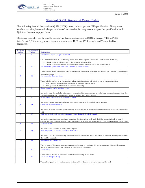
14 Christopher WayEatontown, New Jersey 077241.732.460.90001.732.544.9119 (fax)June 1, 2002Standard Q.931 Disconnect Cause CodesThe following lists all the standard Q.931 (ISDN) cause codes as per the ITU specification. Many other vendors have implemented a larger number of cause codes, but they do not map to the specification and Quintum does not support them.The cause codes list can be used to decode the disconnect reasons in ISDN messages (PBX or PSTN interfaces), Q.931 messages used to communicate over IP, Tenor CDR records and Tenor/Radius messages.Decimal Value HexadecimalValue Definition1 01 Unallocated (unassigned) number.This number is not in the routing table or it has no path across the ISDN cloud (network).1. Check routing table to see it the number is available.2. Check to make sure the correct digits were dialed and it is a valid number.2 02 No route to specified transit network (national use).The number was dialed with a transit network code such as 108880 to from AT&T to MCI and there isno route across.3 03 No route to destination.The dialed number is in the routing plan, but there is no physical route to the destination.1. The PRI D-Channel may be down at one end or the other.2. The span or WAN is not connected correctly.4 04 Send special information tone.Indicates that the called party cannot be reached for reasons that are of a long term nature and that thespecial information tone should be returned to the calling party.5 05 Misdialed trunk prefix (national use).Indicates the erroneous inclusion of a trunk prefix in the called party number.6 06 Channel Unacceptable.Indicates that the channel most recently identified is not acceptable to the sending entity for use in thiscall.7 07 Call awarded and being delivered in an Established channel.Indicates that the user has been awarded the incoming call, and that the incoming call is beingconnected to a channel already established to that user for similar calls (e.g. packet-mode virtual calls).8 08 Pre-Emption.Indicates that the call is being pre-empted.0 09 Pre-Emption – Circuit reserved for reuse.Indicates that the call is being cleared because one of the users involved in the call has requested thatthe call be cleared.16 10 Normal Call Clearing.This is one of the most common cause codes and is received for many reasons. It usually occursbecause someone hung up the call at one side or the other.17 11 User Busy.The number dialed is busy and cannot receive any more calls.18 12 No User Responding.The called party does not respond to the call, or does not wish to answer the call.19 13 No Answer from User (User Alerted).The called party has been alerted to the incoming call, but does not respond with a connect indicationwithin a prescribed period of time.NOTE: This cause is not necessarily generated by Q.931 procedures but may be generated by internalnetwork timers.20 14 Subscriber Absent.Used when a mobile station has logged off, radio contact is not obtained with a mobile station or if apersonal telecommunications user is temporarily not addressable at any user-network interface.21 15 Call Rejected.Indicates that the equipment sending this cause does not wish to accept this call, alth9ough it couldhave accepted the call because the equipment sending this cause is neither busy nor incompatible.May also be generated by the network, indicating that the call was cleared due to a supplementaryservice constraint.22 16 Number Changed.This is returned to a calling party when the called party number indicated by the calling party is nolonger assigned. The new called party number may optionally be included in the diagnostic field. If anetwork does not support this cause value, cause number 1 shall be used.26 1A Non-Selected User Clearing.Indicates that the user has not been awarded the incoming call.27 1B Destination Out-of-Order.This is a working number, but the span to the destination is not active or there is a problem sendingmessages to this destination.28 1C Invalid Number Format (address incomplete).Indicates that the called party cannot be reached because the called party number is not in a validformat or is not complete. This can happen when you are calling out using a network type number(enterprise) when you should be calling out Unknown or National for the Type of Number (TON).29 1D Facility Rejected.This cause is returned when a supplementary service requested by the user cannot be provided by thenetwork.30 1E Response to STATUS ENQUIRY.This cause is included in the STATUS message when the reason for generating the STATUS messagewas the prior receipt of a STATUS ENQUIRY message.31 1F Normal, Unspecified.This is a very common cause code and happens when the network is not able to determine what to dowith the call being made.34 22 No Circuit/Channel Available.There are no B-Channels available to handle the selected call.38 26 Network Out-of-Order.Indicates that the network is not functioning correctly and that the condition is likely to last a relativelylong period of time.39 27 Permanent Frame Mode Connection Out-of-Service.This cause is included in a STATUS message to indicate that a permanently established frame modeconnection is out-of-service.40 28 Permanent Frame Mode Connection Operational.This cause is included in a STATUS message to indicate that a permanently established frame modeconnection is operational and capable of carrying user information.41 29 Temporary Failure.The call was disconnected due to a network failure.The network is not functioning correctly and that the condition is not likely to last a long period of time;e.g. the user may wish to try another call attempt almost immediately.42 2A Switching Equipment Congestion.Indicates that the switching equipment generating this cause is experiencing a period of high traffic.43 2B Access Information Discarded.Indicates that the network could not deliver access information to the remote user as requested, i.e.user-to-user information, low layer compatibility, high layer compatibility, or sub-address, as indicatedin the diagnostic.44 2C Requested Circuit/Channel not Available.This cause is returned when the circuit or channel indicated by the requesting entity cannot be providedby the other side of the interface.This may happen when you get in a glare condition: Both sides are selected top-down or bottom-upchannel hunting.47 2F Resource Unavailable, Unspecified.Used to report a resource unavailable event only when no other cause in the resource unavailable classapplies.49 31 Quality of Service Not Available.Used to report that the requested Quality of Service, as defined in Recommendation X.213, cannot beprovided (e.g. throughput or transit delay cannot be supported).50 32 Requested Facility Not Subscribed.This cause indicates that the user has requested a supplementary service which is implemented by theequipment which generated this cause, but the user is not authorized to use.53 35 Outgoing Calls Barred Within Closed User Group (CUG).Indicates that although the calling party is a member of the CUG for the outgoing CUG call, outgoingcalls are not allowed for this member of the CUG.55 37 Incoming Calls Barred within CUG.Indicates that although the called party is a member of the CUG for the incoming CUG call, incomingcalls are not allowed to this member of the CUG.57 39 Bearer Capability Not Authorized.Indicates that the user has requested a bearer capability which is implemented by the equipment, whichgenerated this cause but the user is not authorized to use.58 3A Bearer Capability Not Presently Available.Indicates that the user has requested a bearer capability, which is implemented by the equipment whichgenerated this cause but which is not available at this time.62 3E Inconsistency in Designated Outgoing Access Information and Subscriber Class.This cause indicates that there is an inconsistency in the designated outgoing access information andsubscriber class.63 3F Service or Option Not Available, Unspecified.Used to report a service or option not available event only when no other cause in the serive or optionnot available class applies.65 41 Bearer Capability Not Implemented.Indicates that the equipment sending this cause does not support the bearer capability requested (i.e.requesting 64kb data when only speech is supported).66 42 Channel Type Not Implemented.Indicates that the equipment sending this cause does not support the channel type requested.69 45 Requested Facility Not Implemented.Indicates that the equipment sending this cause does not support the requested supplementary service.70 46 Only Restricted Digital Information Bearer Capability is Available (national use).Indicates that the calling party has requested an unrestricted (64kb) bearer service but that theequipment sending this cause only supports the restricted version of the requested bearer capability.79 4F Service or Option Not Implemented, Unspecified.Used to report a service or option not implemented event only when no other cause in the service oroption not implemented class applies.81 51 Invalid Call Reference Value.Indicates that the equipment sending this cause has received a message with a call reference which isnot currently in use or assigned on the user-network interface. E.G. The call that is being reference bythis value, does not exist on this system.82 52 Identified Channel Does Not Exist.Indicates that the equipment sending this cause has received a request to use a channel not activated onthe interface for a call.For example, if a user has subscribed to those channels on a PRI numbered from 1 to 12 and the userequipment or the network attempts to use channels 13 through 23, this cause is generated.83 53 A Suspended Call Exists, but This Call Identity Does Not.Indicates that a call resume has been attempted with a call identity which differs from that in use forany presently suspended calls(s).84 54 Call Identity in Use.Indicates that the network has received a call suspended request containing a call identity which isalready in use for a suspended call within the domain of interfaces over which the call might beresumed.85 55 No Call Suspended.Indicates that the network has received a call resume request containing a call identity informationelement, which presently does not indicate any suspended call within the domain of interfaces overwhich calls may be resumed.86 56 Call Having the Requested Call Identity Has Been Cleared.Indicates that the network has received a call resume request containing a call identity informationelement indicating a suspended call that has in the meantime been cleared while suspended.87 57 User Not Member of CUG.Indicates that the called user for the incoming CUG call is not a member of the specified CUG or thatthe calling user is an ordinary subscriber calling a CUG subscriber.88 58 Incompatible Destination.The number being dialed is not capable of the type of call.1. Calling a restricted line in unrestricted mode.2. Calling a pots phone using unrestricted mode.Indicates that the equipment sending this cause has received a request to establish a call which has lowlayer compatibility, high layer compatibility, or other compatibility attributes which cannot beaccommodated.90 5A Non-Existent CUG.Indicates that the specified CUG does not exist.91 5B Invalid Transit Network Selection (national use).Indicates that a transit network identification was received which is of an incorrect format as defined inAnnex C/Q.931.95 5F Invalid Message, Unspecified.Used to report an invalid message event only when no other cause in the invalid message class applies.96 60 Mandatory Information Element is Missing.Indicates that the equipment sending this cause has received a message which is missing aninformation element which must be present in the message.97 61 Message Type Non-Existent or Not Implemented.Indicates that the equipment sending this cause has received a message with a message type it does notrecognize either because this is a message not defined or defined but not implemented by theequipment sending this cause.98 62 Message is Not Compatible with the Call State, or the Message Type is Non-Existent or NotImplemented.Indicates that the equipment sending this cause has received a message such that the procedures do notindicate that this is a permissible message to receive while in the call state, or a STATUS message wasreceived indicating an incompatible call state.99 63 An Information Element or Parameter Does Not Exist or is Not Implemented.Indicates that the equipment sending this cause has received a message which includes informationelement(s)/parameter(s) not recognized because the information element identifier(s)/parametername(s) are not defined or are defined but not implemented by the equipment sending the cause. 100 64 Invalid Information Element Contents.The call has an information element that is not understood by the switch being called. This cause isusually followed by the information element that is causing the problem.101 65 The Message is Not Compatible with the Call State.Indicates that a message has been received which is incompatible with the current call state for this call. 102 66 Recovery on Timer Expired.This occurs when ISDN messages don’t arrive in specified time according to the Q.931 specification.This cause is sometimes followed by the timer that has expired.103 67 Parameter Non-Existent or Not Implemented – Passed On (national use).Indicates that the equipment sending this cause has received a message which includes parameters notrecognized because the parameters are not defined or are defined but not implemented by theequipment sending the cause.110 6E Message with Unrecognized Parameter Discarded.Indicates that the equipment sending this cause has discarded a received message, which includes aparameter that is not recognized.111 6F Protocol Error, Unspecified.Used to report a protocol error event only when no other cause in the protocol error class applies. 127 7F Interworking, Unspecified.Indicates that there has been interworking with a network which does not provide causes for actions ittakes. Thus, the precise cause for a message which is being sent cannot be ascertained.。
视频会议标准

• 图像更新请求
– 是编码器对下帧图像进行编码. 命令通过 C&I BAS codes (见 H.221).
复用 - H.221
• 定义帧结构:
– 复用多种业务(Audio, Video, Data) – 对多个 64 kbps信道进行同步操作,并复用到更 高速率 – 端到端信令
H.221 帧结构
• H.323 –在IP网络上进行多媒体会议的 ITU建议 • 在H.320基础上建立, 并且包括了部分H.320协议
H.320
H.323
Audio Video Data Control
G.711, G.722, G.728 G.711, G.722, G.728, G.723 H.261, H.263 H.261, H.263 LSD, HSD, T.120 [LSD, HSD], T.120 H.242, H.243, H.230 H.225, H.245
H.221 帧结构实例
• G.711/G.722 & H.26x at 128Kbps Bonding
Bit Number 1 2 3 4 5 6 7 8 FAS BAS 56Kbps 1 8 9 16 70.4Kbps 1 2 3 4 5 6 7 8
Frame of 80 octets 64Kbps Channels
H.225
H.245
T.124 T.122 T.125 T.123 RTP
RTCP
TCP
UDP
IP
H.323 协议 (TCP/IP)
• TCP/IP – 包括
– TCP - Transmission Control Protocol
• • • • • • • • 面向连接 (需要确认) 可靠的, 数据流传输业务 错误检查/更正 …..会产生时延...
Q.850到SIP 的代码转换表
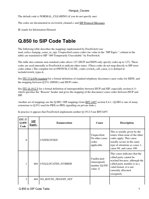
The default code is NORMAL_CLEARING (if you do not specify one)The codes are documented in src/switch_channel.c and SIP Protocol MessagesIE stands for Information ElementQ.850 to SIP Code TableThe following table describes the mappings implemented by FreeSwitch (seemod_sofia.c:hangup_cause_to_sip). Unspecified causes codes (no value in the "SIP Equiv." column in the table) are translated to SIP "480 Temporarily Unavailable" by FreeSwitch.The table also contains non-standard codes above 127 (ISUP and ISDN only specify codes up to 127). These codes are used internally to FreeSwitch to indicate other states. (These codes do not map directly to SIP error codes either.) The complete list of SWITCH_CAUSE_ codes (switch_call_cause_t) is defined ininclude/switch_types.h.See ITU-T Q.850 standard for a formal definition of standard telephony disconnect cause codes for ISDN, and the mapping between Q.931 (DSSS1) and ISUP codes.See ITU Q.1912.5 for a formal definition of interoperability between ISUP and SIP, especially section 6.11 which specifies the "Reason" header and gives the mapping of the disconnect cause codes between ISUP and SIP.Another set of mappings are the Q.SIG / SIP mappings from RFC 4497 section 8.4.1. (Q.SIG is one of many extensions to Q.931 used for PBX-to-PBX signalling on private links.)In practice it appears that FreeSwitch implements neither Q.1912.5 nor RFC4497.No route to specified transit network (national use) [Q.850]This cause indicates that the equipment sending this cause has received a request to route the call through a particular transit network, which it does not recognize. The equipment sending this cause does not recognize the transit network either because the transit network does not exist or because that particular transit network, while it does exist, does not serve the equipment which is sending this cause.3404NO_ROUTE_DESTINATION No route todestination[Q.850]This cause indicates that thecalled party cannot bereached because the networkthrough which the call hasbeen routed does not servethe destination desired. Thiscause is supported on anetwork dependent basis.6CHANNEL_UNACCEPTABLE channelunacceptable[Q.850]This cause indicates that thechannel most recentlyidentified is not acceptable tothe sending entity for use inthis call.7CALL_AWARDED_DELIVERED call awarded,being deliveredin anestablishedchannel[Q.850]This cause indicates that theuser has been awarded theincoming call, and that theincoming call is beingconnected to a channelalready established to thatuser for similar calls (e.g.packet-mode x.25 virtualcalls).16NORMAL_CLEARING normal callclearing[Q.850]This cause indicates that thecall is being cleared becauseone of the users involved inthe call has requested that thecall be cleared. Under normalsituations, the source of thiscause is not the network.17486USER_BUSY user busy[Q.850]This cause is used to indicate that the called party is unable to accept another call becausethe user busy condition has been encountered. This cause value may be generated by the called user or by the network. In the case of user determined user busy it is noted that the user equipment is compatible with the call.18408NO_USER_RESPONSE no userresponding[Q.850]This cause is used when acalled party does not respondto a call establishmentmessage with either analerting or connect indicationwithin the prescribed periodof time allocated.19480NO_ANSWER no answer fromuser (useralerted)[Q.850]This cause is used when thecalled party has been alertedbut does not respond with aconnect indication within aprescribed period of time.Note - This cause is notnecessarily generated byQ.931 procedures but may begenerated by internal networktimers.20480SUBSCRIBER_ABSENT subscriberabsent [Q.850]This cause value is usedwhen a mobile station haslogged off, radio contact isnot obtained with a mobilestation or if a personaltelecommunication user istemporarily not addressableat any user-network interface.Sofia SIP will normally raiseUSER_NOT_REGISTEREDin such situations.21603CALL_REJECTED call rejected[Q.850]This cause indicates that the equipment sending this cause does not wish to accept this call, although it could have accepted the call because the equipment sending this cause is neither busy nor incompatible. The network may also generate this cause, indicating that the call was cleared due to asupplementary service constraint. The diagnostic field may contain additional information about the supplementary service and reason for rejection.22410NUMBER_CHANGED numberchanged[Q.850]This cause is returned to acalling party when the calledparty number indicated by thecalling party is no longerassigned, The new calledparty number may optionallybe included in the diagnosticfield. If a network does notsupport this cause, cause no:1, unallocated (unassigned)number shall be used.23410REDIRECTION_TO_NEW_DESTINATION This cause is used by a general ISUP protocol mechanism that can be invoked by an exchange that decides that the call should be set-up to a different called number. Such an exchange can invoke a redirection mechanism, by use of this cause value, to request a preceding exchange involved in the call to route the call to the new number.25483EXCHANGE_ROUTING_ERROR This cause indicates that the destination indicated by the user cannot be reached, because an intermediate exchange has released the call due to reaching a limit in executing the hop counter procedure. This cause is generated by an intermediate node, which when decrementing the hop counter value, gives the result 0.27502DESTINATION_OUT_OF_ORDER destination outof order[Q.850]This cause indicates that the destination indicated by the user cannot be reached because the interface to the destination is not functioningcorrectly. The term "not functioning correctly" indicates that a signal message was unable to be delivered to the remote party;e.g. a physical layer or data link layer failure at the remote party, or user equipment off-line.28484INVALID_NUMBER_FORMAT invalid numberformat (addressincomplete)[Q.850]This cause indicates that thecalled party cannot bereached because the calledparty number is not in a validformat or is not complete.29501FACILITY_REJECTED facilitiesrejected[Q.850]This cause is returned when asupplementary servicerequested by the user cannotbe provide by the network.30RESPONSE_TO_STATUS_ENQUIRY response toSTATUSINQUIRY[Q.850]This cause is included in theSTATUS message when thereason for generating theSTATUS message was theprior receipt of a STATUSINQUIRY.31480NORMAL_UNSPECIFIED normal,unspecified[Q.850]This cause is used to report anormal event only when noother cause in the normalclass applies.34503NORMAL_CIRCUIT_CONGESTION nocircuit/channelavailable[Q.850]This cause indicates that thereis no appropriatecircuit/channel presentlyavailable to handle the call.38503NETWORK_OUT_OF_ORDER network out oforder [Q.850]This cause indicates that thenetwork is not functioningcorrectly and that thecondition is likely to last arelatively long period of timee.g. immediatelyre-attempting the call is notlikely to be successful.41503NORMAL_TEMPORARY_FAILURE temporaryfailure [Q.850]This cause indicates that the network is not functioning correctly and that the condition is not likely to last a long period of time; e.g. the user may wish to try anothercall attempt almost immediately.42503SWITCH_CONGESTION switchingequipmentcongestion[Q.850]This cause indicates that theswitching equipmentgenerating this cause isexperiencing a period of hightraffic.43ACCESS_INFO_DISCARDED accessinformationdiscarded[Q.850]This cause indicates that thenetwork could not deliveraccess information to theremote user as requested, i.e.user-to-user information, lowlayer compatibility, highlayer compatibility orsub-address as indicated inthe diagnostic. It is noted thatthe particular type of accessinformation discarded isoptionally included in thediagnostic.44503REQUESTED_CHAN_UNAVAIL requestedcircuit/channelnot available[Q.850]This cause is returned whenthe other side of the interfacecannot provide the circuit orchannel indicated by therequesting entity.45PRE_EMPTED47resourceunavailable,unspecified[Q.850]This cause is used to report aresource unavailable eventonly when no other cause inthe resource unavailable classapplies.50FACILITY_NOT_SUBSCRIBED requestedfacility notsubscribed[Q.850This cause indicates that theuser has requested asupplementary service, whichis available, but the user isnot authorized to use.52403OUTGOING_CALL_BARRED outgoing callsbarredThis cause indicates thatalthough the calling party is amember of the CUG for theoutgoing CUG call, outgoingcalls are not allowed for thismember of the CUG.54403INCOMING_CALL_BARRED incoming callsbarred This cause indicates that although the called party is a member of the CUG for theincoming CUG call, incoming calls are not allowed to this member of the CUG.57403BEARERCAPABILITY_NOTAUTH bearercapability notauthorized[Q.850]This cause indicates that theuser has requested a bearercapability that isimplemented by theequipment which generatedthis cause but the user is notauthorized to use.58503BEARERCAPABILITY_NOTAVAIL bearercapability notpresentlyavailable[Q.850]This cause indicates that theuser has requested a bearercapability which isimplemented by theequipment which generatedthis cause but which is notavailable at this time.63SERVICE_UNAVAILABLE service oroption notavailable,unspecified[Q.850]This cause is used to report aservice or option notavailable event only when noother cause in the service oroption not available classapplies.65488BEARERCAPABILITY_NOTIMPL bearercapability notimplemented[Q.850]This cause indicates that theequipment sending this causedoes not support the bearercapability requested.66CHAN_NOT_IMPLEMENTED channel typenotimplemented[Q.850]This cause indicates that theequipment sending this causedoes not support the channeltype requested69501FACILITY_NOT_IMPLEMENTED requestedfacility notimplemented[Q.850]This cause indicates that theequipment sending this causedoes not support therequested supplementaryservices.79501SERVICE_NOT_IMPLEMENTED service oroption notimplemented,unspecified[Q.850]This cause is used to report aservice or option notimplemented event onlywhen no other cause in theservice or option notimplemented class applies.81INVALID_CALL_REFERENCE invalid callreference value This cause indicates that the equipment sending this causecall reference which is not currently in use on the user-network interface.88488INCOMPATIBLE_DESTINATION incompatibledestination[Q.850]This cause indicates that theequipment sending this causehas received a request toestablish a call which has lowlayer compatibility, highlayer compatibility or othercompatibility attributes (e.g.data rate) which cannot beaccommodated.95INVALID_MSG_UNSPECIFIED invalidmessage,unspecified[Q.850]This cause is used to reportan invalid message event onlywhen no other cause in theinvalid message class applies.96MANDATORY_IE_MISSING mandatoryinformationelement ismissing[Q.850]This cause indicates that theequipment sending this causehas received a message whichis missing an informationelement which must bepresent in the message beforethat message can beprocessed.97MESSAGE_TYPE_NONEXIST message typenon-existent ornotimplemented[Q.850]This cause indicates that theequipment sending this causehas received a message with amessage type it does notrecognize either because thisis a message not defined ofdefined but not implementedby the equipment sending thiscause.98WRONG_MESSAGE message notcompatiblewith call stateor messagetypenon-existent ornotimplemented.[Q.850]This cause indicates that theequipment sending this causehas received a message suchthat the procedures do notindicate that this is apermissible message toreceive while in the call state,or a STATUS message wasreceived indicating anincompatible call state.99IE_NONEXIST Informationelement /This cause indicates that the equipment sending this causenon-existent or not implemented [Q.850]includes information element(s)/parameter(s) not recognized because the informationelement(s)/parameter name(s) are not defined or are defined but not implemented by the equipment sending the cause. This cause indicates that the informationelement(s)/parameter(s) were discarded. However, the information element is not required to be present in the message in order for the equipment sending the cause to process the message.100INVALID_IE_CONTENTS Invalidinformationelementcontents[Q.850]This cause indicates that theequipment sending this causehas received and informationelement which it hasimplemented; however, oneor more fields in the I.E. arecoded in such a way whichhas not been implemented bythe equipment sending thiscause.101WRONG_CALL_STATE message notcompatiblewith call state[Q.850]This cause indicates that amessage has been receivedwhich is incompatible withthe call state.102504RECOVERY_ON_TIMER_EXPIRE recovery ontimer expiry[Q.850]This cause indicates that aprocedure has been initiatedby the expiration of a timer inassociation with errorhandling procedures. This isoften associated with NATproblems. Ensure that "NATMapping Enable" is turned onin your ATA. If it is not NATrelated it can sometimes beprovider related, make sure toensure another outboundprovider does not solve theproblem.103MANDATORY_IE_LENGTH_ERROR parameter This cause indicates that thenon-existent or not implemented -passed on (national use) [Q.850]equipment sending this cause has received a message which includes parameters not recognized because the parameters are not defined or are defined but not implemented by the equipment sending this cause. The cause indicates that the parameter(s) were ignored. In addition, if the equipment sending this cause is an intermediate point, then this cause indicates that the parameter(s) were passed unchanged.111PROTOCOL_ERROR protocol error,unspecified[Q.850]This cause is used to report aprotocol error event onlywhen no other cause in theprotocol error class applies.127INTERWORKING Interworking,unspecified[Q.850]This cause indicates that aninterworking call (usually acall to SW56 service) hasended.487487ORIGINATOR_CANCEL 500CRASH501SYSTEM_SHUTDOWN 502LOSE_RACE503MANAGER_REQUEST This cause is used when you send an api command to make it hangup. For example uuid_kill <uuid>600BLIND_TRANSFER601ATTENDED_TRANSFER 602ALLOTTED_TIMEOUT 603USER_CHALLENGE 604MEDIA_TIMEOUT605PICKED_OFF This cause means the call was picked up by intercepting it from another extension (i.e. dialing **ext_number from another extension).606USER_NOT_REGISTERED 607PROGRESS_TIMEOUTSIP to Q.850 Code TableThese mappings are taken from RFC 4497 section 8.4.4.See alsoredirect• respond• Hangup_CausesSee also 11。
- 1、下载文档前请自行甄别文档内容的完整性,平台不提供额外的编辑、内容补充、找答案等附加服务。
- 2、"仅部分预览"的文档,不可在线预览部分如存在完整性等问题,可反馈申请退款(可完整预览的文档不适用该条件!)。
- 3、如文档侵犯您的权益,请联系客服反馈,我们会尽快为您处理(人工客服工作时间:9:00-18:30)。
The format of and the codes used in the service information octet are described in 14.2/Q.704. The service indicator for the ISDN User Part is coded 0101.
Recommendation Q.763 (03/93)
1
1.2 Circuit identification code The format of the circuit identification code (CIC) is shown in Figure 2.
8
7
6
5
4
3
2
1
Circuit identification code (least significant bits)
INTERNATIONAL TELECOMMUNICATION UNION
ITU-T
TELECOMMUNICATION STANDARDIZATION SECTOR OF ITU
Q.763
(03/93)
SPECIFICATIONS OF SIGNALLING SYSTEM No. 7
FORMATS AND CODES OF THE ISDN USER PART OF SIGNALLING SYSTEM No. 7
ITU-T Recommendation Q.763
(Previously “CCITT Recommendation”)
FOREWORD
The ITU Telecommunication Standardization Sector (ITU-T) is a permanent organ of the International Telecommunication Union. The ITU-T is responsible for studying technical, operating and tariff questions and issuing Recommendations on them with a view to standardizing telecommunications on a worldwide basis. The World Telecommunication Standardization Conference (WTSC), which meets every four years, established the topics for study by the ITU-T Study Groups which, in their turn, produce Recommendations on these topics. ITU-T Recommendation Q.763 was revised prepared by the ITU-T Study Group XI (1988-1993) and was approved by the WTSC (Helsinki, March 1-12, 1993).
The signalling information field of each message signal unit containing an ISDN User Part message consists of an integral number of octets and encompasses the following parts (see Figure 1):
ITU 1994
All rights reserved. No part of this publication may be reproduced or utilized in any form or by any means, electronic or mechanical, including photocopying and microfilm, without permission in writing from the ITU.
NOTE – The SLS bits are set to the four least significant bits of the CIC.
_______________
1) The symbol @ in this Recommendation means for national use only.
Optional part
FIGURE 1/Q.763 ISDN User Part message parts
1.1 Routing label
The format and codes used for the routing label are described in 2.2/Q.704. For each individual circuit connection, the same routing label must be used for each message that is transmitted for that connection.
2
In this Recommendation, the expression “Administration” is used for conciseness to indicate both a
telecommunication administration and a recognized operating agency.
___________________
NOTES
1
As a consequence of a reform process within the International Telecommunication Union (ITU), the CCITT
ceased to exist as of 28 February 1993. In its place, the ITU Telecommunication Standardization Sector (ITU-T) was
Spare
CIC most significant bits
FIGURE 2/Q.763 Circuit identification field
NOTE – The service information octet, the routing label and circuit identification code are not included in the SCCP user data parameter transferred between the ISDN User Part and signalling connection control part.
A description of the various message parts is given in the following subclauses.
Routing label Circuit identification code
Message type code Mandatory fixed part Mandatory variable part
created as of 1 March 1993. Similarly, in this reform process, the CCIR and the IFRB have been replaced by the
Radiocommunication Sector.
In order not to delay publication of this Recommendation, no change has been made in the text to references containing the acronyms “CCITT, CCIR or IFRB” or their associated entities such as Plenary Assembly, Secretariat, etc. Future editions of this Recommendation will contain the proper terminology related to the new ITU structure.
Page 1 6 8 60 71 81
Recommendation Q.763 (03/93)
i
Recommendation Q.763
Recommendation Q.763 (03/93)
FORMATS AND CODES1) OF THE ISDN USER PART OF SIGNALLING SYSTEM No. 7
Recommendation Q.763 (03/93)
CONTENTS
1 General ........................................................................................................................................................... 2 Parameter formats and codes.......................................................................................................................... 3 ISDN User Part parameters ............................................................................................................................ 4 ISDN user part messages and codes............................................................................................................... Annex A – Interpretation of spare codes ................................................................................................................. Annex B – General description of component encoding rules ................................................................................