emerson ETC-08-NT 温控器
温控器使用指南

温控器使用指南温控器是一种用于控制温度的设备,广泛应用于家庭和办公环境中。
本文将为您提供温控器的使用指南,帮助您更好地了解和操作这一设备。
一、温控器的基本原理温控器通过感知环境温度,并根据预设的温度范围来控制相关设备的运行,以维持室内温度在一个舒适的范围内。
温控器通常由温度传感器、控制器和输出设备组成。
二、温控器的安装1. 选择合适的位置:温控器应安装在室内温度变化较为均匀的位置,避免阳光直射或靠近热源。
2. 固定安装:使用螺丝或胶水将温控器固定在墙壁或合适的位置上,确保其稳定可靠。
3. 连接电源:将温控器与电源连接,确保电源稳定可靠,并遵循电器安全操作规范。
三、温控器的设置1. 了解温控器的功能:不同型号的温控器具有不同的功能,您需要仔细阅读使用手册,了解温控器的各项功能和操作方法。
2. 设置温度范围:根据个人需求,通过温控器的设置功能,设定室内温度的上限和下限,确保温度在舒适范围内波动。
3. 设置时间表:一些高级温控器具有时间表功能,您可以根据每天不同的时间段,设置不同的温度要求,以提高能源利用效率。
四、温控器的使用1. 启动和关闭:按下温控器上的开关按钮,可启动或关闭温控器。
在不需要控制温度时,建议关闭温控器以节省能源。
2. 调节温度:根据个人需求,通过温控器上的调节按钮,调整设定温度。
温控器将根据设定值自动控制相关设备的运行。
3. 定期维护:定期清洁温控器表面,避免灰尘或其他污物影响其正常运行。
如发现异常情况,及时联系专业人员进行维修或更换。
五、温控器的注意事项1. 避免过度调节温度:频繁调节温度可能会增加能源消耗,建议根据实际需要设定合理的温度范围,避免过度使用。
2. 注意安全:使用温控器时,务必注意电器安全,避免触摸电器内部零部件或将液体溅入温控器内部。
3. 定期检查:定期检查温控器的工作状态,确保其正常运行。
如发现异常情况,应及时处理或联系专业人员进行维修。
六、温控器的优势1. 节约能源:通过合理控制温度,温控器可以帮助节约能源,并减少能源浪费。
温控器设置方法
温控器设置方法温控器是一种非常实用的家用电器,它可以帮助我们在家中保持舒适的温度。
正确地设置温控器不仅可以提高生活质量,还可以节约能源。
接下来,我将向大家介绍温控器的设置方法。
首先,我们需要了解温控器的基本功能和操作按钮。
通常,温控器上会有温度调节按钮、模式选择按钮、定时开关按钮等。
在进行设置之前,我们需要确保温控器已经连接到电源并处于工作状态。
接着,我们可以根据实际需要选择合适的模式。
通常,温控器会有制冷模式和制热模式。
在夏季需要降温时,我们可以选择制冷模式;而在冬季需要加热时,则可以选择制热模式。
有些温控器还会有除湿模式和送风模式,根据实际需求选择合适的模式。
调节温度也是设置温控器的重要步骤。
根据个人的喜好和室内的实际情况,我们可以通过温度调节按钮将温度设置为最舒适的状态。
一般来说,夏季的室内温度应该控制在25摄氏度左右,而冬季的室内温度则应该控制在18摄氏度左右。
除了模式和温度的设置,定时开关功能也是温控器的一大特点。
通过定时开关按钮,我们可以设置温控器的开关机时间,这样可以在不使用空调或暖气时自动关闭,节约能源的同时也能保持舒适的室内环境。
最后,我们需要注意保持温控器的清洁和维护。
定期清洁温控器的表面和通风口,确保其正常运行。
在使用过程中,如果发现温控器出现故障或异常情况,应该及时联系专业人士进行维修和保养。
总的来说,正确地设置温控器可以帮助我们更好地享受舒适的室内环境,同时也可以节约能源。
通过选择合适的模式、调节合适的温度、使用定时开关功能以及定期维护,我们可以更好地利用温控器,提高生活质量。
希望以上介绍对大家有所帮助,谢谢阅读!。
温控器说明书
温控器说明书温控器说明书1. 简介温控器是一种用于控制温度的设备,能够自动感知环境温度,并根据设定的温度范围进行自动调节。
本说明书将介绍温控器的基本功能、特点以及使用方法。
2. 功能特点- 温度感知:温控器能够准确感知环境温度,并将温度数据实时反馈给用户。
- 温度调节:用户可以通过温控器设定温度范围,温控器会根据设定值进行自动调节。
- 显示屏:温控器配备了一个清晰的显示屏,用于显示当前温度和设定的温度范围。
- 定时功能:温控器支持定时功能,用户可以预先设置温度调节时间,方便根据需求灵活调整。
3. 使用方法3.1 查看当前温度步骤:1. 打开温控器电源。
2. 查看温控器显示屏上方的当前温度数字。
3.2 设定温度范围步骤:1. 按下温控器上的设定按钮,进入温度设定模式。
2. 在显示屏上使用调节按钮,设定所需的最低和最高温度。
3. 确认设置后,按下设定按钮以保存设定值。
3.3 手动调节温度步骤:1. 按下温控器上的调节按钮,进入手动调节模式。
2. 使用调节按钮,逐步调整温度。
3. 调整完成后,等待温控器自动稳定温度。
3.4 使用定时功能步骤:1. 按下温控器上的定时按钮,进入定时设定模式。
2. 使用调节按钮,设定所需的定时时间。
3. 确认设置后,按下定时按钮以启动定时功能。
4. 安全注意事项为了确保安全使用温控器,请注意以下事项:- 请确保在使用温控器时,电源连接良好,没有松动或损坏的情况。
- 请勿将水或其他液体溅入温控器内部,以免引发短路或其他安全问题。
- 请勿在温控器上放置易燃物品或其他有潜在危险的物品。
- 请定期检查温控器的电源线是否损坏,及时更换以避免意外发生。
5. 常见问题解答5.1 温控器显示屏不亮或显示异常怎么办?- 请检查温控器的电源是否已连接,以及电源线是否损坏。
- 如以上情况均无问题,请联系售后服务中心进行维修。
5.2 温控器无法自动调节温度怎么办?- 请检查温控器的温度传感器是否正常工作。
上海美娅比热流道 美娅比温度控制器 TC 系列 说明书
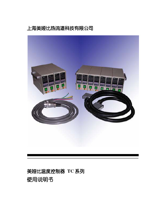
上海美娅比热流道科技有限公司目 录操作注意事项 (1)1. 产品介绍 (2)2. 产品型号及相关部件名称2.1 TC系列温控器规格 (3)2.2 相关部件名称规格 (4)3. 温控器面板按键及功能介绍3.1 前面板 (5)3.2 后面板 (6)4. 使用操作4.1基本操作方法 (7)4.2 参数说明及出厂设定值 (10)5. 常见异常现象的处理方法 (14)附录1. 接线盒的接线示意图(日本Fisa使用例) (15)2. 温控器内部接线图 (18)1)本产品没有防水功能,不能受水、油等溶剂的浸淋,避免放在灰尘大、有湿气的环境中。
2)本产品用于注塑模具的温度调控,禁止使用于其它用途和设备。
3)移动温控器和温控器使用完毕后,应关闭电源开关。
4)必须正确连接地线。
5)拆装模具上的接插件时,应关闭电源开关。
接插件的孔内不许用螺丝刀等金属件插入,以免触电及发生火灾。
6)请使用产品参数中指定规格的保险丝。
7)无控制对象时不要启动自整定功能。
8)禁止私自对本产品进行拆装和改造。
1.产品介绍TC系列温控器是专为热流道系统设计和使用的智能化高精度温度控制器,它能将热流道系统的温度自动控制在最佳注塑条件。
由于采用了微控制器,所以能对不同的热流道系统自动设定最佳控制参数,控温精确,稳定性好,还具有自动报警功能。
操作简单便捷。
采用独立回路,每个控温单元可单独进行参数设置和控温。
PID自整定,对不同的热流道系统自动设定最佳控制参数。
具有温度上限和下限报警功能。
美娅比温控器采用的是模块化结构,具有完全互换性,安装使用灵活。
每一路控温单元除了对外的接口,完全是独立的,所以用户若要增加控温点数,只需购买相应的控温单元拼装上去,再适当的调换接线座即可。
两段温度设定延时控制功能。
在多点热流道系统中,对于容易高温分解、碳化的塑料,由于加热速度的不同,会对其质量产生一定影响。
为了保证加热速度均衡,该温控器增加了两段温度延时控制功能。
其工作原理是:负载加热到过渡温度后会在该温度保持一段时间,然后再升温至最终所需的使用控制温度。
温控仪说明书
:加热器断线报警(CTL-6*3
D:
范围内报警
S
:加热器断线报警(CTL-12*3
E:
附待机上限偏差报警
R
:控制环断线报警*4
F:
附待机下限偏差报警
V
:上限设定值报警
G;
附待机上下限偏差报警
W
:下限设定值报警
⑦第一报警(ALM1,⑧第二报警(ALM2 *2
H:上限输入值报警
⑨通信功能(仅限CD系列)
设定模式 参数设定模式
4工程师参数设定模式
第4篇通讯篇(仅限CD系列表)
第5篇其它
第
1.型号定义
请参照下列代码表确认产品是否与您指定的型号一致。
CD/CH□01/02□ □ □-□ □*□ □-□ □
① ② ③ ④ ⑤ ⑥ ⑦ ⑧ ⑨ ⑩
①规格尺寸 详见第1篇节
②控制类型
F:PID动作及自动演算(逆动作)
⑺本系列仪器无电源开关和保险丝,如需可加装。
保险丝型号:延时保险
⑻当为电流输入时,必须在输入端子间接入250Q(土%±10ppm或
更大)的电阻,由客户自己解决。
⑼不要过分旋紧端子螺钉。请使用合适的端子螺丝接线片(螺丝型号M3X6建议
力矩[])。
4.规格
输入
种类:
a)热电偶:
K,J,R, S, B, E,T,N, U, L,PLH,W5Re/W26Re
•空调的直吹。
•室内使用,勿置于阳光直射下。
•热辐射积累之处。
3.
端子构成
接线注意事项
⑴热电偶输入,应使用对应的补偿导线。
⑵热电阻输入,应使用低电阻且无差别的3根导线。
⑶输入信号线应远离仪器电源线,动力电源线和负荷线以避免产生杂讯干扰。
温控器设置方法

温控器设置方法温控器是一种用来控制温度的设备,广泛应用于家庭、办公室、工厂等各种场所。
正确的设置温控器可以帮助我们更好地调节环境温度,提高生活和工作的舒适度。
下面将介绍温控器的设置方法,希望能对大家有所帮助。
首先,我们需要了解温控器的基本功能和操作界面。
通常,温控器的操作界面包括温度调节按钮、模式选择按钮、定时器、显示屏等。
在开始设置之前,确保温控器已经连接好电源并处于工作状态。
接着,我们可以按照以下步骤进行温控器的设置:1. 温度调节,通过温度调节按钮,我们可以设置温控器所控制的环境温度。
一般来说,温控器的温度调节范围为5℃-35℃,根据实际需求进行调节。
调节时,可以通过温度显示屏实时查看当前设定的温度值。
2. 模式选择,大多数温控器具有多种工作模式,如制冷模式、制热模式、除湿模式、自动模式等。
根据实际需要,选择相应的工作模式。
比如,在夏季可以选择制冷模式,而在冬季则选择制热模式。
3. 定时设置,温控器通常还配有定时开关功能,可以根据个人作息习惯和节能需求,在一定时间段内自动开启或关闭。
通过定时器按钮,设置好开关机的时间和温度,让温控器更加智能化和节能。
4. 温度校准,有些温控器还提供温度校准功能,可以根据实际环境温度对温控器进行校准,确保温度显示的准确性。
5. 其他功能设置,根据温控器的具体型号和功能,还可以进行一些其他功能的设置,比如风速调节、节能模式、温度单位切换等。
在设置完成后,我们需要留意温控器的工作状态,确保它按照我们的设置进行正常工作。
同时,定期清洁和维护温控器,保持其良好的工作状态,延长使用寿命。
总的来说,温控器的设置方法并不复杂,只要掌握了基本操作,就能轻松完成设置。
正确的设置温控器可以为我们的生活和工作带来更多的舒适和便利。
希望以上介绍能帮助大家更好地使用温控器,享受舒适的温度调节体验。
施耐德1 8 din微处理器温控器es ed系列-sw版本3.00-说明书
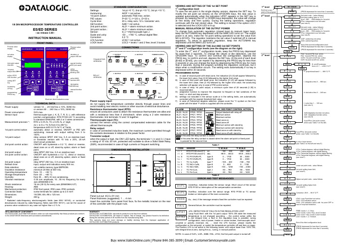
1/8 DIN MICROPROCESSOR TEMPERATURE CONTROLLERES/ED SERIES- sw release 3.00 -INSTRUCTION MANUALFRONT PANELElectronic block extraction screwTE CHNICAL DATAPower supply: version 12 … 24 Vdc/Vac ± 10%, 50/60 Hz;or version 80 … 240 Vac ± 10%, 50/60 Hz.Power consumption: 5VA max.Sensor input: thermocouple type J, K, E, T, R, S, L; with referencejunction compensation; RTD Pt100 Ω/0 °C accordingto standard DIN43760; with 2 or 3 wires connection. Measurement precision *: RTD ± 0.3% fs, TC ± 0.4% fs, ±1 digit;(tc-r, tc-S ± 1% fs from 0 to 200°C)temperature drift 0.01% fs/°C of Tamb.1st point control action: automatic direct or reverse, ON/OFF or PID withautotuning; manual with output setting from 0 to100%.1st point output: relay version SPDT 250 Vac, 5 A on resistive load;or transistor version with 15 Vdc ± 20%, 20 mAshort-circuit protected.2nd point control action: ON/OFF with hysteresis ± 0.2 °C, direct or reverse,dead zone on or off, stand-by option; alarm or fixedpoint.2nd point output: relay SPDT 250 Vac, 5 A on resistive load.3rd point control action: ON/OFF with hysteresis ± 0.2 °C, direct or reverse,dead zone on or off, stand-by option; alarm or fixedpoint.3rd point output: relay SPST 250 Vac, 5 A on resistive load.Refresh time: input, output and indication every 500 ms.Data retention: non volatile memory type EEPROM.Insulation resistance: minimum 20 MΩ at 500 Vdc.Operating temperature: from -10 … +55 °C.Storage temperature: from -20 … +65 °C.Humidity: from 35 … 85% rH non condensing.Vibration resistance: 0.35 mm amplitude, 10…55 Hz frequency for everyaxis(EN60068-2-6)Shock resistance: 18 ms (30 G) for every axis (EN60068-2-27) Housing:ABSMechanical protection: IP50 front panel, IP20 case, IP00 contacts Connection leads: screw terminals for cables up to 2.5 mm². Dimensions: 1/8 DIN; 48 x 96 x 125 mmWeight:400g.*Radiated radio-frequency electromagnetic fields (see ENV 50140), or conducted disturbances induced by radio-frequency fields (see ENV 50141), can be the cause of process value variations in any case not higher than ± 2 % fs.STANDARD CONFIGURATIONSettings: 1st pt.=0 °C; 2nd pt.=10 °C; 3rd pt.=10 °C.Autotuning: AtOF = not active.1st point action: automatic Pidd max. action.PID values: P=20 °C; I=120 s.; D=30 s.Cycle time: 20 s. relay vers.;12 s. transistor vers.Adt function: Adt0 = not active.2nd point action.: AL21 = alarm minimum action.3rd point action.: AL31 = alarm minimum action.Sensor: tc-J = thermocouple type J.Scale and unity: -50 ... +760 °C, without digital filter.Correction:0.0°CLFA function: LFA0 = not active.LOCK level: LOC3 = levels 1 and 2 free, level 3 locked.CONNECTIONSdo not supply the temperature controller directly through power lines andavoid installing near electric motors or other sources of electrical disturbance.Resistance thermometer input (RTD):ensure all conductors used to attach the resistance thermometer are alike andwith a resistance less than 4 ohms/each; when using a 2 wire resistancethermometer, link terminals 13 and 14 together.Thermocouple input (TC):connect the sensor using the correct compensated extension cable for theutilized thermocouple.Relay output:in case of connected inductive loads, the maximum current permitted throughthe contacts decreases in relation to the power factor.Transistor output:when the output is high, the ON1 LED lights, the terminals 1 (+) and 3 (-) havea rating of 15 Vdc 20 mA, protected and suitable to drive a Solid State Relay(SSR), recommended in case of high currents or frequent switching.Panel cut-out: 45.5 x 91 mmPanel thickness (suggested): 1 … 4 mmInsert the controller from panel front face, fix the metallic bracket on the rearof the controller with the proper nuts.VIEWING AND SETTING OF THE 1st SET POINT1st configuration levelTo view the set point in the single display version, depress the SET key. Tomodify the set point act directly on the UP/DOWN keys, the new value isupdated automatically when the indication UPDT appears or the SET key ispressed. By keeping the UP or DOWN keys depressed, the value will changeat first slowly and then quickly. During the setting operations, regulationcontinues with the last stored value. The setting is locked if the option LOC1is selected and the LOCK LED is lit up.MANUAL REGULATION OF THE OUTPUT POWERTo change from automatic regulation (closed loop) to manual (open loop),keep the AUTO/MAN key depressed until the MAN LED turns on. The outputpower is at zero, make the 1st point setting operations to set the value fromM0 to M100%. The regulator maintains the set value if switched off in manualregulation. To return to automatic regulation, keep the AUTO/MAN keydepressed until the MAN LED turns off.VIEWING AND SETTING OF THE 2nd AND 3rd SET POINTS2nd and 3rd configuration levels (see the diagram on the right)To enter the 2nd and 3rd configuration levels, keep the PROG key depressedfor more than 2 seconds. To change the values or the selections, use theUP/DOWN keys. To confirm and continue the configuration, depress thePROG key; to confirm and exit, depress the SET key. At the end of each level[End2] or [End3], you can repeat it by depressing the PROG key for less than2 seconds or you can change the level by depressing the PROG key for morethan 2 seconds. During the program scrolling the regulation continues, but itstops when a modification occurs. The setting exits automatically if no key isdepressed within 30 seconds.PROGRAMMING NOTESA)in case of second point with dead zone, the indication [2 LO] will appear followed bythe lower limit value, then [2 HI] followed by the higher limit value.B)in case of third point with dead zone, the indication [3 LO] will appear followed bythe lower limit value, then [3 HI] followed by the higher limit value; the autotuningselection will appear only in case of PID control action.C)in case of relay 1st point output, a minimum cycle time of 20 seconds [t 20] isrecommended.D)adaptative function to improve the response to frequent or fast variations of theload, i.e. start and stop process.E)settings not included in the sensor scale or in the setting limits, are automaticallycorrected with the nearest threshold limit value.F)in case of Fahrenheit degrees selection, please cover the °C symbol on the frontpanel with the label °F which is supplied with the controller.Table 1CODE SENSOR °C SCALE °F SCALEr t l RTD Pt100 ohm/0°C int. -150 ... 450 -200 (850)r t d RTD Pt100 ohm/0°C dec. -99.9 ... 450.0 -99.9 ... 850.0t c S TC Pt10%Rh-Pt, type S 0 ... 1700 30 (3000)t c r TC Pt13%Rh-Pt, type R 0 ... 1700 30 (3000)t c t TC Cu-CuNi, type T -100 ... 400 -150 (750)t c E TC NiCr-CuNi, type E 0 ... 600 0 (1100)t c C TC NiCr-NiAl, type K -100 ... 1250 -150 (2300)t c J TC Fe-Cuni, type J -50 ... 760 -50 (1400)t c L TC Fe-Cuni, type L -50 ... 760 -50 (1400)Table 2ERROR AND TEST MESSAGGESUnderflow, indication below the sensor range. Short circuit of the sensorRTD Pt100 or interruption of the compensation connection.Overflow, indication over the sensor range. RTD Pt100 or TC sensorbroken or interruption of the main connection.Au...-test, if the message remains fixed the controller must be repaired.General failure; the controller must be repaired.LFA: DETECTION OF FAULTS IN THE REGULATION LOOPLoop Fault Alert: with the 1st point output 100% ON state the measuredtemperature is not changed according ... the control action within thes...red integral time; a fault in the regulation loop is possible: wrongconfiguration, lack of power, heater or cooler broken, thermocouple short-circuited or polarity reversed, etc. ... reset the LFA function, please modify theconfiguration or the set-point, or switch the temperature controller off and then on again.The function LFA is not active in the following cases: with output lower than 100% ON,with integral time at zero, during the au...tuning, in manual position.NOTE: In case of OvFL, UnFL, 8888, FAIL, LFA2, the first point output is turned off.DECLARATION OF CONFORMITYWe DATALOGIC AUTOMATION declare under our sole responsibility that these products are conform to the 2004/108/CE Directives and successive amendments. WARRANTYDATALOGIC AUTOMATION warrants its products to be free from defects.DATALOGIC AUTOMATION will repair or replace, free of charge, any product found to be defectiveduring the warranty period of 36 months from the manufacturing date.This warranty does not cover damage or liability deriving from the improper application ofDATALOGIC AUTOMATION products.U n F LO v F L8 8 8 8F A I LL F A 1L F A 2Buy:|Phone844-385-3099|Email:*************************。
艾默生精密空调维护手册v12

艾默生精密空调维护手册v12 XXX精密空调维护手册H52主办2016年4月21日订定目录第一章概述1.1简介本手册旨在为用户提供Emerson精密空调的维护指南。
1.2主要部件1.2.1室内机室内机是Emerson精密空调系统的核心部件。
它包含压缩机、蒸发器、冷凝器和膨胀阀等重要组件。
1.2.2控制器控制器是Emerson精密空调系统的关键部件。
它可以监测和控制室内温度、湿度和空气质量等参数,确保系统正常运行。
第二章各个功能模块介绍2.1制冷系统制冷系统是Emerson精密空调系统的核心部件。
它可以通过压缩、冷凝、蒸发和膨胀等过程将热量从室内移出,使室内温度保持稳定。
为了确保制冷系统正常运行,用户需要定期清洗和更换过滤器、检查制冷剂压力和泄漏等问题。
删除明显有问题的段落)改写后的第一章概述:XXX精密空调维护手册旨在为用户提供维护指南,确保系统正常运行。
室内机是系统的核心部件,包含压缩机、蒸发器、冷凝器和膨胀阀等重要组件。
控制器是关键部件,可以监测和控制室内温度、湿度和空气质量等参数。
改写后的第二章各个功能模块介绍:制冷系统是Emerson精密空调系统的核心部件,通过压缩、冷凝、蒸发和膨胀等过程将热量从室内移出,使室内温度保持稳定。
为确保制冷系统正常运行,用户需要定期清洗和更换过滤器、检查制冷剂压力和泄漏等问题。
2.1.1 压缩机压缩机是空调系统中最重要的组件之一。
其主要功能是将低压低温的气体压缩成高压高温的气体,使其能够在冷凝器中释放热量。
2.1.2 冷凝器冷凝器是将压缩机压缩出的高温高压气体冷却成高压液体的重要组件。
其主要原理是通过散热器来散热,使气体冷却并凝结成液体。
2.1.3 膨胀阀膨胀阀是空调系统中的一个重要组件,其主要功能是控制制冷剂的流量和压力。
它可以通过自动调节制冷剂的流量来维持系统的稳定性。
2.1.4 蒸发器蒸发器是空调系统中的一个重要组件,其主要功能是将低压低温液体制冷剂蒸发成低温低压气体,吸收空气中的热量,从而实现制冷效果。
PID温控器使用说明书
使用说明书U-HSX1300-MICN2 1.产品介绍傻瓜式模糊PID温控器/调节仪采用模糊PID算式,无需人工整定参数,控温精度基本达±0.5℃,无超调、欠调,性价比高。
傻瓜式操作,7款外型尺寸,支持33种信号输入功能,可与各类传感器、变送器配合使用,实现对温度、压力、液位、容量、力等物理量的测量显示,并配合各种执行器对电加热设备和电磁、电动阀进行PID调节和控制、报警控制、数据采集等功能。
适用于工业炉,电炉,烘箱,试验设备,制鞋机械,注塑机械,包装机械,食品机械,印刷机械等行业。
支持2路报警功能,支持1路控制输出或支持采用标准MODBUS RTU协议的RS485通讯接口,1路DC24V配电输出。
输入端、输出端、电源端光电隔离。
100-240VAC/DC或12-36V DC开关电源供电,标准卡入式安装,工作环境温度在0-50℃,且相对湿度5-85%RH无凝结。
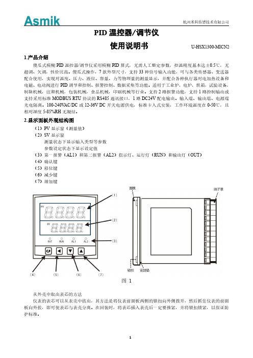
2.显示面板外观结构图(1)PV显示窗(测量值)(2)SV显示窗测量状态下显示输入类型等参数参数设定状态下显示设定值(3)第一报警(AL1)和第二报警(AL2)指示灯、运行灯(RUN)和输出灯(OUT)(4)确认键(5)移位键(6)减少键(7)增加键图1从外壳中取出表芯的方法仪表的表芯可以从表壳中拔出,其方法是将仪表前面板两侧的锁扣向外侧拨开,然后抓住仪表的前面板向外拔,即可使表芯与表壳分离。
在回装时,将表芯插入表壳后一定要推紧,并将锁扣锁紧,以保证防护标准。
外形尺寸开孔尺寸外形尺寸开孔尺寸160*80mm(横式)152*76mm48*96mm(竖式)45*92mm 80*160mm(竖式)76*152mm72*72mm(方式)68*68mm 96*96mm(方式)92*92mm48*48mm(方式)45*45mm 96*48mm(横式)92*45mm3.接线图2规格尺寸为A、B、C、D、E型接线图注:横竖式仪表后盖接线端子方向不一样,见示意图3图3图4规格尺寸为F型接线图图5规格尺寸为H型接线图注1:上述接线图中在同一组端子标有不同功能的,只能选择其中一种功能。
ETC-08-NT 温控器速查手册
资料版本:V1.0 归档时间:2008-03-06 BOM 编号:31011620ETC-08-NT 温控器速查手册提示:在开始使用之前,请仔细阅读操作指示、注意事项,以减少意外的发生。
负责产品安装、操作的人员必须经严格培训,遵守相关行业的安全规范,严格遵守本手册提供的相关设备注意事项和特殊安全指示,按正确的操作方法进行设备的各项操作。
型号说明如下图所示。
输出方式。
R:表示继电器输出T:表示晶体管输出输入方式。
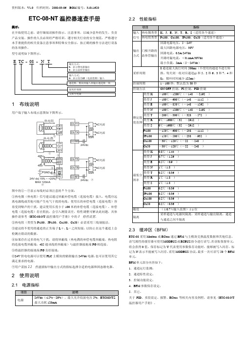
N:表示没有CT(电流检测)输入通道数,模块的输入和输出通道数一致温度控制器艾默生电器E TC -08-N T1 布线说明用户端子输入布线示意图如下图所示。
电源⑥电源电源电源图中的①~⑦表示布线时必须注意的7个方面:①热电偶(热电阻)信号建议通过屏蔽补偿电缆(连接电缆)接入。
电缆应远离电源线或其他可能产生电气干扰的电线。
使用长的补偿电缆(连接电缆)容易受到噪声的干扰,建议使用长度小于100米的补偿电缆(连接电缆)。
补偿电缆(连接电缆)存在阻抗,会引入测量误差,特性调整可解决此问题,具体操作请参考《ETC-08-NT 温控器用户手册》中的3 特性设置。
②热电阻(类型为Pt100、JPt100、Cu100、Cu50)必需采用三线制接法。
③建议将不使用的通道的正负端子L +、L -之间短接,以防止在这个通道上会检测出错误的数据。
④如果存在过多的电气干扰,请将屏蔽线(热电偶的补偿电缆屏蔽端,热电阻的连接电缆屏蔽端,485通讯线的屏蔽端)与温控器接地端PG 相连接。
⑤将温控器的接地端PG 良好接地。
⑥24V 供电电源可以使用PLC 主模块的辅助输出24Vdc 电源,也可以使用其它满足要求的电源。
⑦用户需按2.2 性能指标中输出方式的指标选择合适的电源和固态继电器。
2 使用说明2.1 电源指标项目 说明电源 24Vdc (-15%~20%),最大允许纹波电压5%,ETC08NTZ最大功耗120mA2.2 性能指标项目 指标热电偶类型K 、J 、E 、N 、T 、R 、S (适用各个通道) 输入信号热电阻类型Pt100、Cu100,JPt100,Cu50(适用各个通道) 输出方式门极开路的晶体管输出回路电源电压:5~24V最大回路电源电压:30V 回路电流:0.3A/24Vdc 开路时漏电流:<0.1mA/30Vdc 最小负载:5mA (5~24Vdc )采样周期 8通道最大执行时间500ms (不使用的通道不进行转换,每关闭一组对应通道(1和5、2和6、3和7、4和8),循环时间减少125ms ) 控制周期1~100秒,默认值为30秒控制方法 ON/OFF 控制,PI 控制,PID 控制类型K -100℃~1200℃(-148℉~2192℉) 类型J -100℃~600℃(-148℉~1112℉) 类型E -100℃~850℃(-148℉~1562℉) 类型N-100℃~1200℃(-148℉~2192℉) 类型T-200℃~300℃(-328℉~572℉)类型R 0℃~1600℃(32℉~2912℉) 类型S 0℃~1600℃(32℉~2912℉) Pt100 -150℃~600℃(-238℉~1112℉) JPt100 -150℃~500℃(-238℉~932℉) Cu100 -30℃~120℃(-22℉~248℉) 额定温度范围Cu50-30℃~120℃(-22℉~248℉)类型K 0.8℃(1.44℉)类型J 0.7℃(1.26℉) 类型E 0.5℃(0.9℉) 类型N 1℃(1.8℉)类型T 0.2℃(0.36℉) 类型R 1℃(1.8℉) 类型S 1℃(1.8℉) Pt100 0.2℃(0.36℉) JPt100 0.2℃(0.36℉) Cu100 0.2℃(0.36℉) 最低分辨率Cu50 0.2℃(0.36℉)精度 (±0.7%输入范围)±1位隔离 采样通道与电源间隔离,采样通道与输出隔离,通道与通道之间不隔离2.3 缓冲区(BFM )ETC-08采用Modbus 或ECbus 通过BFM 与主模块交换温度数据和其他信息。
温控器设置方法

温控器设置方法温控器是一种用于控制温度的设备,广泛应用于家庭、工业和商业环境中。
正确设置温控器不仅可以提高生活和工作的舒适度,还可以节约能源。
下面将介绍温控器的设置方法,帮助您正确、方便地使用温控器。
首先,确保您已经阅读了温控器的用户手册。
不同品牌和型号的温控器可能有不同的设置方法和功能,因此在进行设置之前,了解用户手册中的相关信息是非常重要的。
接下来,找到温控器上的“设置”按钮。
通常情况下,温控器会有一个“设置”按钮,通过按压或长按这个按钮,可以进入温控器的设置界面。
在设置界面中,您可以看到各种设置选项,比如温度调节、定时开关机、制冷/制热模式等。
根据您的实际需求,逐一设置这些选项。
首先,设置温度。
根据当前环境温度和您的舒适需求,调节温控器上的温度设置按钮。
通常情况下,温控器会有上下箭头按钮,通过按压这些按钮,可以调节设定的温度值。
其次,设置定时开关机。
如果您希望在特定的时间段内自动开启或关闭温控器,可以在设置界面中找到定时开关机选项,然后设置开启和关闭的时间。
再次,根据实际需要选择制冷或制热模式。
如果您需要降低室内温度,选择制冷模式;如果您需要提高室内温度,选择制热模式。
最后,保存设置。
在完成所有设置后,按照用户手册的指引,保存您的设置。
通常情况下,您可以通过按压“确认”或“保存”按钮来保存设置。
除了基本的温度、定时和模式设置外,一些高级温控器还可能具有更多的功能,比如节能模式、智能控制、远程控制等。
如果您的温控器具有这些功能,可以根据需要进行相应的设置。
总之,正确设置温控器可以提高生活和工作的舒适度,同时也有助于节约能源。
通过阅读用户手册,找到设置按钮,逐一设置温度、定时、模式等选项,并保存设置,您就可以轻松地使用温控器了。
希望以上介绍的温控器设置方法对您有所帮助。
温控器使用说明书
规格说明:◆面板尺寸:75×35(单位:mm) ◆建议安装孔尺寸:71×30(单位:mm) ◆外壳:阻燃ABS 塑料◆防护等级:IP45 ◆使用环境:◇工作环境温度:-10℃~+60℃;◇工作环境相对湿度:20%~85%(不凝露)。
◆主要功能及电参数:◇电源电压:12VAC/VDC;◇电源功耗:≤5W;◇温度测量范围:-40℃~+50℃;◇测量精度:±l℃;◇分辩率:1℃;◇开机延时保护时间:0~9min ◇高低温报警设置范围:O℃~20℃并可以取消;◇温度校正范围:-5℃~+5℃;◇除霜周期:0~99h;◇除霜时间:0~99min ◇压缩机输出接点:10A 240VAC;除霜输出接点:10A 240VAC;◇传感器:NTC 103AT。
参数设定操作:◆修改参数值操作:◇按住[Set]键3S 进入参数项选择模式,设置指示灯亮;LED 显示某一参数项;◇按[▲]或[▼]键选择参数项(F1�6�7�6�7F7),按[▲]增加,按[▼]减少,再按[Set]键显示相应参数项的参数值;◇按住[Set]键不松手,同时再按一下[▲]键或[▼]键改变参数值,如连续按[▲]或[▼]键不放,参数值自动快速增大或减小;松开[Set]键,单按[▲]或[▼]键选择下一个参数项,按住[Set]键不松手,同时再按一下[▲]键或[▼] 键改变参数值,重复以上步骤进行所有参数值的设定;◇所有参数设定完毕,按一下[Rst]键保存所有设定值,返回温度测量状态设置指示灯灭。
若30S 后无键操作,机器自动存储设定值并返回温度测量状态,设置指示灯灭。
若在参数设定完成后30S 内未按[Rst]键保存就断电,机器仍按原来的参数值运行。
◆查看参数值操作:◇按一下[▲]键,显示已设定上限值2S,返回当前温度显示状态;◇按一下[▼]键,显示已设定下限值2S,返回当前温度显示状态;◇按一下[Set]键,显示已设定除霜间隔、最大除霜时间各2S,返回当前温度显示状态。
温控器使用说明.

温控器使⽤说明.温控显⽰器使⽤说明书⽬录⼀、概述⼆、技术指标三、功能与型号分类四、产品功能说明五、⾯板六、⼯作状态及按键功能七、操作流程⼋、电脑通讯功能九、电流输出功能⼗、现场故障处理⼩常识⼗⼀、传感器总成⼗⼆、电⽓接线图⼗三、安装⼗四、服务⼀、概述HY-BWDK330A系列⼲式变压器电脑温控箱是我公司为⼲式电⼒变压器可靠运⾏⽽设计的最新⼀代多功能智能温度控制箱。
它采⽤美国最先进RISC单⽚计算机和⾼分辨率A/D转换器,并结合I2C总线调整与存储技术,利⽤预埋在⼲式变压器三相绕组中三只⾼线性精度的Pt100铂热敏电阻来检测及显⽰变压器绕组的温升,具有相应的超⾼温报警及超⾼温跳闸控制输出功能,能够⾃动启动冷却风机对变压器绕组进⾏强迫风冷,提⾼变压器的负载容量,保证变压器安全运⾏。
依据JB/T7631-94《变压器⽤电阻温度计》标准设计⽣产。
主要设计特点有:★采⽤新型软硬件抗⼲扰设计,对电快速瞬变、共模与串模、空间磁场及空间射频⼲扰均具有极强的抑制能⼒,并满⾜国际标准(IEC61000)电磁兼容性各项指标。
具有定时检测与校正功能,可随时排除随机⼲扰,并采⽤精密低温系数元器件,可有效抑制零点漂移和温度漂移。
★选⽤功能强⼤的WATCHDOG和上掉电检测模块的RISC单⽚机,可避免温控箱进⼊死循环,使得温控箱在各种条件下均能正常⼯作⽽不需另设复位键。
★综合应⽤单⽚机技术,能有效地判断传感器开路等故障信号,保证了变压器在停、送电情况下,温控箱不会误发出报警或跳闸等信号。
★采⽤了I2C总线调整与存储技术,实现断电数据保存。
温控箱内不⽤电位器调校温度精度⽽采⽤先进的I2C总线调整技术,彻底解决了因使⽤电位器⽽可能产⽣的漂移及接触不良等缺点,使温控箱长期可靠运⾏。
★为⽤户设计出“模拟输出状态检测”功能,⼈性化的设计⼤⼤地⽅便了⽤户在使⽤前对温控箱的检测与调试。
★风机激励(定时启停)功能,定时对风机进⾏检测保护。
★独⽴的4~20mA模拟⼯业标准电流输出功能,满⾜⽤户在远端对变压器温升的监测。
TC-8 温控模块,TC-8温控仪编程手册,8路温控模块编程手册
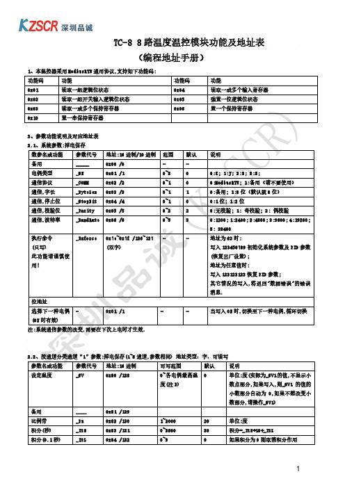
小数部分自动为 0,如果不想改变小
数部分,请操作_SV1)
备用
____
0x81 /129
比例带
_Pu
0x82 /130
1~2000
20
单位:度
积分(秒)
_ItH
0x83 /131
0~3600
30
积分=_ItH*10+_ItL
积分(0.1 秒)
_ItL
0x84 /132
0~9
0
如果积分为 0 则取消积分作用
16 位
通道 2(0.1 度)
0x811 /2065
同上
通道 3(0.1 度)
0x812 /2066
同上
通道 4(0.1 度)
0x813 /2067
同上
通道 5(0.1 度)
0x814 /2068
同上
通道 6(0.1 度)
0x815 /2069
同上
通道 7(0.1 度)
0x816 /2070
同上
通道 8(0.1 度)
通道 7
0x806 /2054
通道 8
0x807 /2055
冷端
0x808 /2056
说明 16 位 同上 同上 同上 同上 同上 同上 同上 同上
2.4.2、通道温度值:(单位 0.1 度,只读),数据类型:有符号字
通道
地址:16 进制 /10 进制
说明
通道 1(0.1 度)
0x810 /2064
_AL1
0x89 /137 0x109 /265 0x189 /393 0x209 /521 0x289 /649 0x309 /777 0x389 /905 0x409 /1033
温控器的设置方法

温控器的设置方法
温控器是一种非常常见的家用电器,它可以帮助我们在家中实
现温度的控制,让我们的生活更加舒适。
然而,对于一些新手来说,温控器的设置可能会有些困难。
不过,只要按照正确的步骤进行操作,其实并不复杂。
接下来,我将为大家介绍温控器的设置方法。
首先,我们需要确保温控器的电源已经连接好,并且温控器的
屏幕已经亮起。
接着,我们可以按照以下步骤进行设置。
1. 语言选择,首先,温控器的屏幕上会显示语言选择的界面,
我们可以根据自己的需要选择合适的语言,然后按确认键进行确认。
2. 时间设置,接下来,屏幕上会显示时间设置的界面,我们可
以根据当前的时间进行调整,一般来说,温控器会有24小时制和
12小时制两种选择,我们可以根据自己的习惯进行设置,然后按确
认键进行确认。
3. 温度设置,在时间设置完成后,屏幕上会显示温度设置的界面,我们可以根据需要将制热温度和制冷温度进行调整,一般来说,制热温度会设置为比较高的温度,而制冷温度会设置为比较低的温
度,然后按确认键进行确认。
4. 工作模式选择,最后,屏幕上会显示工作模式选择的界面,我们可以根据需要选择自动模式、制冷模式或制热模式,然后按确认键进行确认。
通过以上几个步骤的设置,我们就可以完成温控器的设置。
需要注意的是,不同品牌、不同型号的温控器可能会有一些细微的差异,因此在进行设置时,最好还是参考一下对应的使用说明书,以确保设置的准确性。
总的来说,温控器的设置并不复杂,只要按照正确的步骤进行操作,就可以轻松完成。
希望以上介绍对大家有所帮助,祝大家生活愉快!。
温控器使用说明书
一周编程电子智能室内温控器LOGIC 578001使用指南引言感谢您选择了我们的产品及对我们的信任与支持。
本装置是电子式定时恒温器,可设置一星期为周期的运行程序。
通过该装置,可对安装环境内的温度进行十分精确的调节控制,满足用户对创造一个舒适生活环境的要求。
符合标准:符合欧盟法令:EN 60730-1 标准及其修订内容欧盟B.T.73/23/EEC号法令EN 60730-2-7 标准欧盟 E.M.C.89/336/EEC号法令及93/68/EEC修改法令EN 60730-2-9 标准产品规格:电源:二节LR6型1.5V碱性电池温度调节范围:10至35℃显示屏显示之环境温度:0至40℃(分辩率0.1℃)温度修正频率:每分钟一次微分:0.2至0.4K探针传感器:NTC3%保护等级:IP20绝缘等级:热梯度:1K/15分输出:转换继电器触点容量:8(2.5)A250V~作用类型:1BU绝缘条件:正常环境最大工作温度:50℃储存温度:0-60℃防冻温度:6℃恒定运行程序:以一星期为周期设置软件等级:A液晶显示屏夏季/冬季(采暖/空调)切换程序设置中的最小增减允许时间:1小时安装:壁式安装安装及连接:安全预防措施在进行定时恒温器的连接之前,请确认受其控制的设备系统(采暖锅炉、泵和空调系统等)电源已断开,并需检查这些设备的使用电压是否与定时恒温器底座上表明的电压相符(最大250V~).(图4)安装位置定时恒温器须安装在远离热源(暖气装置、阳光、厨房)和门窗之处,安装高度离地面约1.5米。
(图5)安装见图6-7-8电气连接将受定时恒温器控制的设备系统电线与定时恒温器的1号及2号接线柱连接见接线图10所示U=受定时恒温器控制的设备1=共用接线柱2=常开接线柱3=常闭接线柱重要事项:请务必严格遵照相关现行法律的规定及安全规范安装定时恒温器。
电池更换:当在显示屏上闪烁显示“”标志时,定时恒温器还可正常工作约一个月左右,然后将会停止工作并固定显示“”。
恒温控制器用户指南说明书

Step 30. Select the Deadband Value Submenu Press d . The display will show 020.0, otherwisepress b or c.Press d to store and advance to next menu item.Step 31. Enter the Alarm 2 MenuThe display will show ALR2the top menu for Alarm 2.Repeat steps from 29 and 30 to set for Alarm 2 the same conditions as for Alarm 1.Step 32. Configuration of Display Color Selection Press a until the COLR Display Color Selection Menu appears on the Display. Configure COLR as N.CLR /GRN (green), 1.CLR / RED (red), 2.CLR /AMBR (amber). Please refer to the operator’s manual if needed.For color change on Setpoints refer to Owners Manual Section 2.Step 33. Run a TestPress a until reset the controller and return to RUN Mode to display 075.0(Ambient Temperature). Now you are ready to observe temperature as it rises 10°F higher thandisplayed. Touch the tip of the Thermocouple to raise the temperature above the Alarm 2 High value 082.0, and AL2will turn on, and Display Color will change from Green to Amber. Continue touching the tip to raise the temperature above the Alarm 1 High value 087.0and Display Color will change from Amber to Red. Annunciator “1” is turning on and off displaying output 1.Step 11. Enter to the Thermocouple Type Input Submenu Press d to display flashing, previously selected Thermocouple type.Step 12. Scroll through available selection of TC types Press b to sequence thru flashing Thermocouple types,(select k -for type "K" CHROMEGA ®/ALOMEGA ®)J K T E N DIN J R S B C - TC types J k t E N dN J R S b C - DisplayStep 13. Store TC typeAfter you have selected the Thermocouple type press d to store your selection, the instrument automatically advances to the next menu item.Step 14. Enter to Reading Configuration MenuThe display shows RDG Reading Configuration, which is the top menu for 4 submenus: Decimal Point, Degree Units,Filter Constant and Input/Reading Submenus.Step 15. Enter to Decimal Point Submenu Press d to show DEC Decimal Point.Step 16. Display the Decimal Point positionPress d again to display the flashing Decimal Point position.Step 17. Select the Decimal Point position Press b to select FFF.F Decimal Point position.Step 18. Store selected Decimal Point positionBy pressing d momentarily the Decimal Point position will be stored and the instrument will go to the next menu item.Step 19. Enter to Temperature Unit Submenu Display shows TEMP Temperature Unit.Step 20. Display available Temperature Units Press d to display the flashing Degree °F or °C .Step 21. Scroll through Temperature Units selection Press b to select °F Degree.Step 22. Store the Temperature UnitPress d to display momentarily that the Degree Unit has been stored and the instrument will go automatically to the next menu item.Step 23. Enter the Filter Constant Submenu Display shows FLTR Filter Constant Submenu.Step 24. Display the Filter Constant Value Submenu Press d to display the flashing, previously selected Filter Constant.Step 25. Scroll through available Filter Constants Press b to sequence thru Filter Constants 0001, 0002,0004, 0008, 0016, 0032, 0064and 0128.Step 26. Store the Filter ConstantPress d momentarily to store 0004Filter Constant and the instrument will automatically go to the next menu item.Step 27. Enter Alarm 1 MenuPress a until the ALR1Alarm 1 Menu appears on the Display. In the following steps we are going to DisableLatch, Active Above, Deadband 020.0, and above Setpoint 1Value will activate Alarm 1.Step 28. Select Latch Type SubmenuPress d to display flashing DSBL / ENBL .If flashing DSBL is displayed, press a , if ENBL is displayed, press b until DSBL is displayed, then press d to store and go to the next menu item.Step 29. Select the Above Type of Active Submenu Press d . If flashing ABoV Above is displayed, press a ,otherwise press b until ABoV is displayed. Press d to store and advance to next menu item.MQS3716-SM/0305WARNING:These products are not designed for use in, and should not be used for, patient-connected applications.It is the policy of OMEGA to comply with all worldwide safety and EMC/EMI regulations that apply. OMEGA is constantly pursuing certification of its products to the European New Approach Directives. OMEGA will add the mark to every appropriate device upon certification.The information contained in this document is believed to be correct, but OMEGA Engineering, Inc. accepts no liability for any errors it contains, and reserves the right to alter specifications without notice.TRADEMARK NOTICE:®,®,, andare Trademarks ofOMEGA ENGINEERING, INC.®SPECIFICATIONAccuracy:+0.5°C temp;0.03% rdg. process typical Resolution:1°/0.1°; 10 µV process Temperature Stability:0.04°C/°C RTD;0.05°C/°C TC @ 25°C (77°F); 50 ppm/°C process Display:4-digit, 7-segment LED, 57.2 mm (2.25") with red, green, and amber programmable colors for process variable, set point and temperature units.Input Types:Thermocouple, RTD, Analog Voltage and Current TC: (ITS 90)J, K, T, E, R, S, B, C, N, L RTD: (ITS 68)100/500/1000 ohm Pt sensor2-, 3-, or 4-wire; 0.00385 or 0.00392 curve Voltage:0 to 100 mV, 0 to 1 V, 0 to 10 Vdc Current:0 to 20 mA (4 to 20 mA)Output 1†:Relay 250 Vac @ 3 A Resistive Load,SSR, Pulse, Analog Voltage and Current Output 2†:Relay 250 Vac @ 3 A Resistive Load,SSR, Pulse†Only for AlarmsOptions:Communication RS-232 / RS-485 or Excitation:24 Vdc Power:100-240 Vac ±10%,50-60 Hz, 22.5 W Dimensions:289 L x 137 W x 73 D mm(11.75” L x 5.375” W x 2.875” D)Panel Cutout:279.4 L x 116.8 W mm (11.00” L x 4.60” W)Weight:1,360 g (3 lbs)Approvals:per EN 61010-1:2001iLD24 Big Displayhis Quick Start Reference provides information on setting up your instrument for basic operation. The latest complete Communication and Operational Manual as well as free Software and ActiveX Controls are available at or on the CD-ROM enclosed with your shipment .SAFETY CONSIDERATIONThe instrument is a panel mount device protected in accordance with EN 61010-1:2001, electrical safetyrequirements for electrical equipment for measurement, control and laboratory.Remember that the unit has no power-on switch. Building installation should include a switch or circuit-breaker that must be compliant to IEC 947-1 and 947-3.SAFETY:•Do not exceed voltage rating on the label located on the back of the instrument housing.•Always disconnect power before changing signal and power connections.•Do not use this instrument on a work bench without its case for safety reasons.•Do not operate this instrument in flammable or explosive atmospheres.EMC:•Whenever EMC is an issue, always use shielded cables. •Never run signal and power wires in the same conduit.•Use signal wire connections with twisted-pair cables.•Install Ferrite Bead(s) on signal wire close to the instrument if EMC problems persist.。
EMERSON EATC08RE1 空调遥控器说明书

Manuals+— User Manuals Simplified.EMERSON EATC08RE1 Air Conditioner Remote Controller Illustration User ManualHome » Emerson » EMERSON EATC08RE1 Air Conditioner Remote Controller Illustration User Manual EMERSON EATC08RE1 Air Conditioner Remote Controller Illustration User ManualWARNINGLocation of the remote controller.Use the remote controller within a distance of 5 meters from the appliance, pointing it towards the receiver.Reception is confirmed by a beepCAUTIONSStep 2: Install battery inside the remote controller, the positive (+) side up.Step 3: Install the battery cover, make sure the battery cover groove is aligned with the “unlock” sign. Insert a coin vertically in the groove and press it gently, then counter clockwise rotation of 45 degrees, make sure the groove is aligned with the “lock” sign as shown below.WARNING1. Battery must be disposed of properly. Do not short circuit or dispose of in the fire.2. Keep batteries out of the reach of children.3. Caution for ingestion.4. Non-rechargeable batteries are not to be recharged.5. Exhausted batteries are to be removed from the product.Remote Controller SpecificationsModel RG15A(B)/E RG15A3(B)/E RG15A4(B)/E, RG15A5(B)/E Rated Voltage 3.0V( Lithium battery CR2025)Lowest Voltage of CPU Emitting Signal 2.4VSignal Receiving Range5mEnvironment-5 C~60 C(23 F~140 F)NOTE:RG15A5(B)/E RG15A3(B)/EFunction buttonsOperation starts when this button is pressed and stops when the button is pressed again.NOTE: If the unit has ENERGY SAVER function, it will initiate automatically the Energy Saver function under C ool, Dry, and Auto(only Au to-Cooling and Auto-Fan) modes.Push this button to decrease the indoor temperature settingPush this button to activate the Auto Start or Auto Stop program.Push this button, the system will automatically shift to COOL operation with auto fan speed, the setting temperature is O O 26 C/80 F. And the timer setting program will be cancelled.(on some models)Press this button to select the desired operation mode.Push this button to increase the temperature setting.Used to select the desired fan speed.Press this button to activate the Sleep mode. This function is available on COOL, HEAT or AUTO mode only and maintain the most comfortable temperature for you and save energy. For the detail, see sleep operation in USER S MANUAL.Press this button to activate the Energy saving mode. Press it again to stop the function.(on some models)How to use the buttonsAuto operationEnsure the unit is plugged in and power is available.1. Press the ON/OFF button to start the air conditioner.2. Press the MODE button to select Auto.3. Press the TEMP UP/DOWN button to set the desired temperatureNOTE1. In the Auto mode, the air conditioner can logically choose the mode of Cooling, Fan, Heating and by sensingthe difference between the actual ambient room temperature and the set temperature on the remote controller.2. In the Auto mode, you can not switch the fan speed. It has already been automatically controlled.3. If the Auto mode is not comfortable for you , the desired mode can be selected manually.Cooling /Heating/ operationEnsure the unit is plugged in and power is available.1. Press the ON/OFF button to start the air conditioner.2. Press the MODE button to select Cool, Heat (cooling&heating models only) or mode.3. Press the TEMP UP/DOWN button to set the desired temperature.4. Press the FAN button to select the fan speed.NOTEIn the Fan mode, you are not able to control the room temperature either. In this case, only step 1, 2 and 4 may be performed.Dehumidifying operationEnsure the unit is plugged in and power is available.1. Press the ON/OFF button to start the air conditioner.2. Press the MODE button to select Dry.3. Press the TEMP UP/DOWN button to set the desired temperatureNOTEIn the Dehumidifying mode, you can not switch the fan speed. It has already been automatically controlled. Timer operationPress the TIMER button can initiate the Auto-start and Auto-stop setting program of the unit.To set the Auto-start/stop time.1. Press the TIMER button, when the TIMER ON indicator displayed on the LED window of the air conditioner, itindicates the Auto Start setting program is initiated. When the TIMER OFF indicator displayed on the LED window of the air conditioner, it indicates the Auto Stop setting program is initiated.2. Press or hold the Up( ) or Down( ) to hange the Auto time. The control will count down the time remaining untilstart/stop.3. The selected time will register in 5 seconds and the air conditioner will automatically revert back to display theprevious temper- ature setting.4. Turning the unit ON or OFF at any time will cancel the Auto Start/stop function.NOTE: To cancel the TIMER setting, push the TIMER button and press or hold the Up ( ) or Down( ) until 0 hour is displayed on the LCD window of the air conditioner.COMBINED TIMER(Setting both ON and OFF timers simultaneously)AUTO STOP AUTO START(On Stop Start operation)This feature is useful when you want to stop the air conditioner after you go to bed, and start it again in themorning when you wake up or whenyou return home.Example:To stop the air conditioner 2 hours after setting and start it again 10 hours after setting.1. Press the TIMER button until the TIMER OFF indicator is displayed on the LED display of the air conditioner.2. Use the UP/DOWN button to display “2.0” on the LED display of the air conditioner.3. Press the TIMER button again to display the TIMER ON on the LED display of the unit.4. Use the UP/DOWN button to display “10” on the LED display of the unit.5. Wait for 5 seconds until the previous display revert back to the LED window.AUTO START ATUO STOP (Off Start Stop operation)This feature is useful when you want to start the air conditioner before you wake up and stop it after you leave the house.Example:To start the air conditioner 5 hours after setting,and stop it 8 hours after setting.1. Press the TIMER button until the TIMER ON indicator is displayed on the LED display of the air conditioner.2. Use the UP/DOWN button to display “5.0” on the LED display of the air conditioner.3. Press the TIMER button again to display the TIMER OFF on the LED display of the unit.4. Use the UP/DOWN button to display “8.0” on the LED display of the unit.5. Wait for 5 seconds until the previous display revert back to the LED window.Energy saver operationNOTE:Buttons design is based on typical model and might be slightly different from the actual one you purchased, the actual shape shall prevail.All the functions described are accomplished by the unit, if the unit has no this feature, there is nocorresponding operation happened when press the relative button on the remote controller.When there are wide differences between Remote controller Illustration and USERS MANUAL on function description, the description on USERS MANUAL shall prevail.Increase the separation between the equipment and receiver.Connect the equipment into an outlet on a circuit different from that to which the receiver is connected.Consult the dealer or an experienced radio/TV technician for help. Changes or modifications not approved by the party responsible for compliance could void suers authority to operate the equipment.Documents / ResourcesEMERSON EATC08RE1 Air Conditioner Remote Controller Illustration [pdf] User ManualEATC08RE1 Air Conditioner Remote Controller Illustration, EATC08RE1, Air Conditioner Remote Controller Illustration, Conditioner Remote Controller Illustration, Remote Controller Illustration, Controller IllustrationReferencesSearch - Manuals+,。
1NT系列电子温控器产品说明书

16.2
1NT01L-8399
190.0
5.0
374.0
9.0
168.0
9.0
334.4
16.2
1NT01L-8400
200.0
5.0
392.0
9.0
178.0
9.0
352.4
16.2
B
2
1
"CLOSE ON RISE" ACTUATION TEMPERATURES AND TOLERANCES
TRIP TEMPERATURE
REV.
A2 1NT01X-VERT1 C
SCALE 1:2 SOLIDWORKS SHEET 2 OF 2
4
3
2
1
D
APPLICATION WITH RESPECT TO TEMPERATURE SETTINGS, MECHANICAL CYCLE LIFE, ELECTRICAL LOADING AND ENVIRONMENTAL CONDITIONS. THESE DEVICES ARE NOT
INTENDED FOR USE IN APPLICATIONS WHERE EXPOSURE TO CONDENSED OR DRIPPING
15.0
3.0
59.0
5.4
-5.0
4.5
23.0
8.1
1NT01L-83942Leabharlann .03.068.0
5.4
0
4.5
32.0
8.1
1NT01L-8395
25.0
3.0
77.0
5.4
5.0
4.5
41.0
蒂仕特温控器工作原理
蒂仕特温控器工作原理蒂仕特温控器是一种用于调节室内温度的设备,它通过监测环境温度并控制加热或制冷设备的工作来实现温度的调节。
其工作原理基于温度传感器、控制器和执行机构的协同工作。
蒂仕特温控器中的温度传感器是实现温度检测的关键部件。
它能够感知周围环境的温度,并将温度信号转化为电信号传递给控制器。
温度传感器通常采用热敏电阻、热敏电偶或半导体材料等元件,通过测量物体或空气的热量变化来获取温度信息。
接下来,控制器是蒂仕特温控器的核心部件,它根据温度传感器传来的信号进行分析和判断,并根据预设的温度设定值来控制加热或制冷设备的工作。
控制器内部通常包含微处理器、逻辑电路和存储器等组件,可以实现温度数据的处理、逻辑判断和控制命令的输出。
执行机构是根据控制器的指令来调节室内温度的关键组成部分。
执行机构通常包括加热器和制冷器等设备,它们通过电磁阀门或电动阀门的控制,将热能或冷能引入室内,从而调节室内温度。
执行机构的工作状态由控制器根据温度传感器的反馈信号实时调整,以保持室内温度在预设范围内。
蒂仕特温控器的工作原理可以简单总结为以下几个步骤:首先,温度传感器实时监测环境温度,并将温度信号传递给控制器;其次,控制器根据温度信号和预设的温度设定值进行比较和判断,然后输出控制命令;最后,执行机构根据控制命令调节加热或制冷设备的工作状态,以控制室内温度达到预设值。
蒂仕特温控器的工作原理简单而有效,可以广泛应用于家庭、办公室、工厂等各种场所。
它能够实时监测和调节室内温度,提供舒适的室内环境。
同时,蒂仕特温控器还具有节能的特点,可以根据实际需要合理调节加热或制冷设备的使用,减少能源消耗,降低能源成本。
蒂仕特温控器通过温度传感器、控制器和执行机构的协同工作,实现了对室内温度的精确控制。
它的工作原理简单而有效,可以提供舒适的室内环境,并具有节能的特点。
蒂仕特温控器的应用范围广泛,对提高生活和工作的舒适度、降低能源消耗都起到了重要作用。
- 1、下载文档前请自行甄别文档内容的完整性,平台不提供额外的编辑、内容补充、找答案等附加服务。
- 2、"仅部分预览"的文档,不可在线预览部分如存在完整性等问题,可反馈申请退款(可完整预览的文档不适用该条件!)。
- 3、如文档侵犯您的权益,请联系客服反馈,我们会尽快为您处理(人工客服工作时间:9:00-18:30)。
提示
在开始使用之前,请仔细阅读操作指示和注意事项,以减少意外的发生。负责产品安装、操作的人员必须经严格培 训,遵守相关行业的安全规范,严格遵守本手册提供的相关设备注意事项和特殊安全指示,按正确的操作方法进行 设备的各 08 - N T
输出方式。 R:表示继电器输出 T:表示晶体管输出
ETC-08-NT 温控器 用户手册
资料版本 归档时间 BOM 编号
V1.0 2008-05-16 31011647
艾默生网络能源有限公司为客户提供全方位的技术支持,用户可与就近的艾默生网络能源有限公司办事处 或客户服务中心联系,也可直接与公司总部联系。
艾默生网络能源有限公司 版权所有,保留一切权利。内容如有改动,恕不另行通知。
艾默生网络能源有限公司 地址:深圳市南山区科技工业园科发路一号 邮编:518057 公司网址: 客户服务热线:400-887-6510 客户服务投诉热线:0755-86010800 E-mail:info@
输入方式。 N:表示没有CT(电流检测)输入
通道数,模块的输入和输出通道数一致
温度控制器 艾默生
目录
第一章 产品介绍 ................................................................................................................................................................. 1
2.2 连线.......................................................................................................................................................................................13 2.2.1 布线注意事项...........................................................................................................................................................13 2.2.2 布线说明...................................................................................................................................................................13 2.2.3 电缆规格...................................................................................................................................................................14 2.2.4 连接电源线...............................................................................................................................................................14 2.2.5 连接输入/输出信号线..............................................................................................................................................15 2.2.6 连接通讯线...............................................................................................................................................................15
1.4.1 电源指标.....................................................................................................................................................................3 1.4.2 性能指标.....................................................................................................................................................................3 1.5 缓冲区(BFM)说明.............................................................................................................................................................4 1.5.1 通道运行监测.............................................................................................................................................................4 1.5.2 通道特性设定.............................................................................................................................................................5 1.5.3 控制功能设定.............................................................................................................................................................6 1.5.4 多段功能设定.............................................................................................................................................................8 1.5.5 报警功能设定.............................................................................................................................................................9 1.5.6 BFM 参数保存设定 ..................................................................................................................................................10 1.5.7 其它 ..........................................................................................................................................................................10 1.6 附件清单...............................................................................................................................................................................11 第二章 安装接线 ............................................................................................................................................................... 12
2.1 机械安装...............................................................................................................................................................................12 2.1.1 安装位置要求...........................................................................................................................................................12 2.1.2 安装步骤...................................................................................................................................................................12