Instruction for Modeltest
Instruction Manual for Self-Contained, AC-Operated

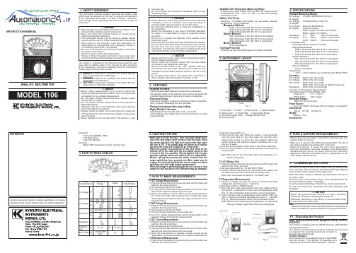
Instruction ManualSelf-Contained, AC-Operated Sensors•Featuring EZ-BEAM ® technology, the specially designed optics and electronics provide reliable sensing without the need for adjustments •30 mm plastic threaded barrel sensor in opposed, retroreflective, or fixed-field sensing modes•Completely epoxy-encapsulated to provide superior durability, even in harsh sensing environments rated to IP69K•Innovative dual-indicator system takes the guesswork out of sensor performance monitoring•20 V ac to 250 V ac (3-wire hookup); SPST solid-state switch output,maximum load 300 mAWARNING: Not To Be Used for Personnel ProtectionNever use this device as a sensing device for personnel protection. Doing so could lead to serious injury or death. This device does not include the self-checking redundant circuitry necessary to allow its use in personnel safety applications. A sensor failure or malfunction can cause either an energized or de-energized sensor output condition.ModelsFixed-Field Mode OverviewS30 Sensor self-contained fixed-field sensors are small, powerful, infrared diffuse mode sensors with far-limit cutoff (a type of background suppression). Their high excess gain and fixed-field technology allow detection of objects of low reflectivity, while ignoring background surfaces.The cutoff distance is fixed. Backgrounds and background objects must always be placed beyond the cutoff distance.•9 m (30 ft) cable: add suffix "W/30" (for example, S303E W/30).•4-pin Micro-style QD models: add suffix "Q1" (for example, S303EQ1). A model with a QD connector requires a mating cable.S30 Sensors AC-Voltage SeriesOriginal Document121519 Rev. A30 December 2015121519Fixed-Field Sensing – Theory of OperationThe S30FF compares the reflections of its emitted light beam (E) from an object back to the sensor’s two differently aimed detectors, R1 and R2. See Figure 1 on page 2. If the near detector's (R1) light signal is stronger than the far detector's (R2) light signal (see object A in the Figure below, closer than the cutoff distance), the sensor responds to the object. If the far detector's (R2) light signal is stronger than the near detector's (R1) light signal (see object B in the Figure below,beyond the cutoff distance), the sensor ignores the object.The cutoff distance for model S30FF sensors is fixed at 200, 400, or 600 millimeters (7.9 in, 16.7 in, or 23.6 in). Objects lying beyond the cutoff distance are usually ignored, even if they are highly reflective. However, under certain conditions,it is possible to falsely detect a background object (see Background Reflectivity and Placement on page 2).or Cutoff Near Detector FarDetectorEmitter Object is sensed if amount of light at R1 is greater than the amount of light at R2Figure 1. Fixed-Field Concept Figure 2. Fixed-Field Sensing AxisIn the drawings and information provided in this document, the letters E, R1, and R2 identify how the sensor’s three optical elements (Emitter “E”, Near Detector “R1”, and Far Detector “R2”) line up across the face of the sensor. Thelocation of these elements defines the sensing axis, see Figure 2 on page 2. The sensing axis becomes important in certain situations, such as those illustrated in Figure 5 on page 3 and Figure 6 on page 3.Device SetupSensing ReliabilityFor highest sensitivity, position the target object for sensing at or near the point of maximum excess gain. Maximum excess gain for all models occurs at a lens-to-object distance of about 40 mm (1.5 in). Sensing at or near this distance makes the maximum use of each sensor’s available sensing power. The background must be placed beyond the cutoff distance. Note that the reflectivity of the background surface also may affect the cutoff distance. Following these guidelines will improve sensing reliability.Background Reflectivity and PlacementAvoid mirror-like backgrounds that produce specular reflections. A false sensor response occurs if a background surface reflects the sensor’s light more to the near detector (R1) than to the far detector (R2). The result is a false ON condition (Figure 3 on page 3). To correct this problem, use a diffusely reflective (matte) background, or angle either the sensor or the background (in any plane) so the background does not reflect light back to the sensor (Figure 4 on page 3).Position the background as far beyond the cutoff distance as possible.An object beyond the cutoff distance, either stationary (and when positioned as shown in Figure 5 on page 3), ormoving past the face of the sensor in a direction perpendicular to the sensing axis, may cause unwanted triggering of the sensor if more light is reflected to the near detector than to the far detector. The problem is easily remedied by rotating the sensor 90° (Figure 6 on page 3). The object then reflects the R1 and R2 fields equally, resulting in no false triggering. A better solution, if possible, may be to reposition the object or the sensor. - Tel: +1-763-544-3164P/N 121519 Rev. ACutoff Highly Reflective BackgroundFigure 3. Reflective Background - ProblemR1 = Near Detector R2 = Far Detector E = EmitterCutoff DistanceFigure 4. Reflective Background - SolutionR1 = Near Detector R2 = Far Detector E = EmitterCutoff Reflective BackgroundorMoving ObjectA reflective background object in this position or moving across the sensor face in this axis and direction may cause false sensor response.Figure 5. Object Beyond Cutoff - ProblemE = EmitterR1 = Near Detector R2 = Far DetectorCutoff A reflective background object in this position or moving across thesensor face in this axis will be ignored.Figure 6. Object Beyond Cutoff - SolutionColor SensitivityThe effects of object reflectivity on cutoff distance, though small, may be important for some applications. It is expected that at any given cutoff setting, the actual cutoff distance for lower reflectance targets is slightly shorter than for higher reflectance targets. This behavior is known as color sensitivity.For example, an excess gain of 1 for an object that reflects 1/10 as much light as the 90% white card is represented by the horizontal graph line at excess gain = 10. An object of this reflectivity results in a far limit cutoff of approximately 190mm (7.5 in) for the 200 mm (8 in) cutoff model, for example; 190 mm represents the cutoff for this sensor and target.These excess gain curves were generated using a white test card of 90% reflectance. Objects with reflectivity of less than 90% reflect less light back to the sensor, and thus require proportionately more excess gain in order to be sensed with the same reliability as more reflective objects. When sensing an object of very low reflectivity, it may be especially important to sense it at or near the distance of maximum excess gain.P/N 121519 Rev. A - Tel: +1-763-544-31643SpecificationsSupply Voltage and Current20 av V to 250 V ac (50 Hz to 60 Hz)Average current: 20 mA Peak current:200 mA at 20 V ac 500 mA at 120 V ac 750 mA at 250 V acSupply Protection CircuitryProtected against transient voltagesOutput ConfigurationSPST solid-state ac switch; three-wire hookup; light operate or dark operate, depending on modelLight Operate: Output conducts when sensor sees its own (or the emitter’s) modulated lightDark Operate: Output conducts when the sensor sees darkRequired Overcurrent ProtectionWARNING: Electrical connections must be made by qualified personnel in accordance with local and national electrical codes and regulations.Overcurrent protection is required to be provided by end product application per the supplied table.Overcurrent protection may be provided with external fusing or via Current Limiting, Class 2 Power Supply.Supply wiring leads < 24 AWG shall not be spliced.For additional product support, go to .Output Rating300 mA maximum (continuous)Fixed-Field models: derate 5 mA/°C above +50° C (+122° F)Inrush capability: 1 amp for 20 ms, non-repetitive OFF-state leakage current: < 100 mAON-state saturation voltage: 3 V at 300 mA ac; 2 V at 15 mA ac Output Protection CircuitryProtected against false pulse on power-up Output ResponseTime Opposed mode: 16 ms ON, 8 ms OFF Other models: 16 ms ON and OFFNOTE: 100 ms delay on power-up; outputs do not conduct during this time.RepeatabilityOpposed mode: 2 ms Other models: 4 msRepeatability and response are independent of signal strength IndicatorsTwo LEDs (Green and Yellow)Green ON steady: power to sensor is ON Yellow ON steady: sensor sees lightYellow flashing: excess gain marginal (1 to 1.5 times) in light condition ConstructionPBT polyester housing; polycarbonate (opposed-mode) or acrylic lens Environmental RatingLeakproof design rated NEMA 6P, DIN 40050 (IEC IP69K)Connections2 m (6.5 ft) attached cable, or 4-pin Micro-style quick-disconnect fitting Operating ConditionsTemperature: −40 °C to +70 °C (−40 °F to +158 °F)Humidity: 90% at +50 °C maximum relative humidity (non-condensing)Vibration and Mechanical ShockAll models meet Mil. Std. 202F requirements. Method 201A (Vibration;frequency 10 Hz to 60 Hz, max., double amplitude 0.06 inchacceleration 10G). Method 213B conditions H&I. (Shock: 75G with unit operating; 100G for non-operation)CertificationsPerformance CurvesTable 1: Opposed Mode Sensors - Tel: +1-763-544-3164P/N 121519 Rev. ATable 2: Polarized Retro Mode Sensors2Table 3: Fixed-Field Mode Sensors Excess Gain33Performance based on use of a 90% reflectance white test card. Focus and spot sizes are typical.P/N 121519 Rev. A - Tel: +1-763-544-31645DimensionsCabled ModelsYellow LEDQD ModelsWiring DiagramsCabled Emittersbn bu20-250V acQD Emitters (4-pin Micro-Style)All Other Cabled ModelsAll Other QD Models (4-pin Micro-Style)CordsetsAll measurements are listed in millimeters (inches), unless noted otherwise. - Tel: +1-763-544-3164P/N 121519 Rev. ABanner Engineering Corp. Limited WarrantyBanner Engineering Corp. warrants its products to be free from defects in material and workmanship for one year following the date of shipment. Banner Engineering Corp. will repair or replace, free of charge, any product of its manufacture which, at the time it is returned to the factory, is found to have been defective during the warranty period. This warranty does not cover damage or liability for misuse, abuse, or the improper application or installation of the Banner product.THIS LIMITED WARRANTY IS EXCLUSIVE AND IN LIEU OF ALL OTHER WARRANTIES WHETHER EXPRESS OR IMPLIED (INCLUDING, WITHOUT LIMITATION, ANY WARRANTY OF MERCHANTABILITY OR FITNESS FOR A PARTICULAR PURPOSE), AND WHETHER ARISING UNDER COURSE OF PERFORMANCE, COURSE OF DEALING OR TRADE USAGE.This Warranty is exclusive and limited to repair or, at the discretion of Banner Engineering Corp., replacement. IN NO EVENT SHALL BANNER ENGINEERING CORP. BE LIABLE TO BUYER OR ANY OTHER PERSON OR ENTITY FOR ANY EXTRA COSTS, EXPENSES, LOSSES, LOSS OF PROFITS, OR ANY INCIDENTAL, CONSEQUENTIAL OR SPECIAL DAMAGES RESULTING FROM ANY PRODUCT DEFECT OR FROM THE USE OR INABILITY TO USE THE PRODUCT, WHETHER ARISING IN CONTRACT OR WARRANTY, STATUTE, TORT, STRICT LIABILITY, NEGLIGENCE, OR OTHERWISE.Banner Engineering Corp. reserves the right to change, modify or improve the design of the product without assuming any obligations or liabilities relating to any product previously manufactured by Banner Engineering Corp. - Tel: +1-763-544-3164。
数字万用表使用说明书
manual before starting using the instrument. • Save and keep the manual handy to enable quick
(4 ranges) Terminal Voltage:
# CAUTION is reserved for conditions and actions that can cause injury or instrument damage.
# DANGER • Never make measurement on a circuit in which the
# DANGER is reserved for conditions and actions that are likely to cause serious or fatal injury.
# WARNING is reserved for conditions and actions that can cause serious or fatal injury.
The symbol # indicated on the instrument means that the user must refer to related parts in the manual for safe operation of the instrument. Be sure to carefully read the instructions following each symbol in the manual.
4. SPECIFICATIONS
ECE 21

E/ECE/324 )Rev.1/Add.20/Rev.2/Amend.2E/ECE/TRANS/505 )March 25, 2003STATUS OF UNITED NATIONS REGULATIONECE 21UNIFORM PROVISIONS CONCERNING THE APPROVAL OF:VEHICLES WITH REGARD TO THEIR INTERIOR FITTINGSIncorporating:Supplement 2 to the 01 series of amendments Date of Entry into Force: 18.01.98 Corr. 1 to the 01 series of amendments Date of Entry into Force: 08.03.00 Supplement 3 to the 01 series of amendments Date of Entry into Force: 31.01.03E/ECE/324 )Rev.1/Add.20/Rev.2/Amend.2E/ECE/TRANS/505 )March 25, 2003UNITED NATIONSAGREEMENTCONCERNING THE ADOPTION OF UNIFORM TECHNICAL PRESCRIPTIONS FOR WHEELED VEHICLES, EQUIPMENT AND PARTS WHICH CAN BE FITTED AND/OR BE USED ON WHEELED VEHICLES AND THE CONDITIONS FOR RECIPROCAL RECOGNITION OFAPPROVALS GRANTED ON THE BASIS OF THESE PRESCRIPTIONS (*)(Revision 2, including the amendments which entered into force on October 16, 1995)Addendum 20: Regulation No. 21Revision 2 — Amendment 2Supplement 3 to the 01 series of amendments - Date of entry into force: January 31, 2003UNIFORM PROVISIONS CONCERNING THE APPROVAL OF VEHICLES WITH REGARDTO THEIR INTERIOR FITTINGS(*)Former title of the Agreement:Agreement Concerning the Adoption of Uniform Conditions of Approval and Reciprocal Recognition of Approval for Motor Vehicle Equipment and Parts, done at Geneva on March 20, 1958.REGULATION No. 21UNIFORM PROVISIONS CONCERNING THE APPROVAL OF VEHICLES WITH REGARDTO THEIR INTERIOR FITTINGSCONTENTSREGULATION1. Scope2. Definitions3. Application for approval4. Approval5. Requirements6. Modifications and extension of approval of the vehicle type7. Conformity of production8. Penalties for non-conformity of production9. Production definitely discontinued10. Names and addresses of technical services responsible for conducting approval tests, and ofadministrative departmentsANNEXESAnnex 1 Determination of the Head-impact ZoneAnnex 2 Communication concerning the approval or extension or refusal or withdrawal of approval or production definitely discontinued of a vehicle type with regard to its interior fittings,pursuant to Regulation No. 21Annex 3 Arrangements of the approval marksAnnex 4 Procedure for testing energy-dissipating materialsAnnex 5 Procedure for determining the "H" point and the actual torso angle for seating positions in motor vehiclesAnnex 6 Method of measuring projectionsAnnex 7 Apparatus and procedure for application of Paragraph 5.2.1. of this regulationAnnex 8 Determination of a dynamically determined head impact zoneAnnex 9 Typical position of cylindrical test rod in the opening roof and window openingsAnnex 10 Explanatory notesREGULATION No. 21UNIFORM PROVISIONS CONCERNING THE APPROVAL OF VEHICLES WITH REGARDTO THEIR INTERIOR FITTINGS1. SCOPEThis Regulation applies to the interior fittings of vehicles of Category M1 with regard to:1.1the interior parts of the passenger compartment other than the rear-view mirror or mirrors; 1.2the arrangement of the controls;or opening roof, androof1.3 the1.4the seat-back and the rear parts of seats.1.5.power-operation of windows, roof panels and partition systems.2. DEFINITIONSFor the purpose of this Regulation,2.1"approval of a vehicle" means the approval of a vehicle type with regard to its interiorfittings;2.2."vehicle type" with regard to the interior fittings of the passenger compartment meansvehicles of Category M1 which do not differ in such essential respects as:2.2.1.the lines and constituent materials of the bodywork of the passenger compartment;2.2.2.the arrangement of the controls;2.2.3.the performance of the protective system, if the reference zone within the head impact zonedetermined according to Annex 8 (dynamic evaluation) is chosen by the applicant.2.2.3.1. Vehicles that differ only in the performance of the protective system(s) belong to the samevehicle type if they offer an equal or better protection for the occupants compared with thesystem or vehicle submitted to the technical service responsible for conducting the approvaltests.2.3."reference zone"is the head-impact zone as defined in Annex 1 to this Regulation, or atthe choice of the manufacturer, according to Annex 8, excluding the following areas: (seeAnnex 10, explanatory notes, Paragraphs 2.3. and 2.3.1.)2.3.1.the area bounded by the forward horizontal projection of a circle circumscribing the outerlimits of the steering control, increased by a peripheral band 127 mm in width; this area isbounded below by the horizontal plane tangential to the lower edge of the steering controlwhen the latter is in the position for driving straight ahead; (see Annex 10, explanatorynotes, Paragraphs 2.3. and 2.3.1.)2.3.2.the part of the surface of the instrument panel comprised between the edge of the areaspecified in Paragraph 2.3.1. above and the nearest inner side-wall of the vehicle; this partof the surface is bounded below by the horizontal plane tangential to the lower edge of thesteering control and; (see Annex 10, explanatory notes, Paragraphs 2.3. and 2.3.1.)2.3.3.the windscreen side pillars; (see Annex 10, explanatory notes, Paragraphs 2.3. and 2.3.1.) 2.4."level of the instrument panel" means the line defined by the points of contact of verticaltangents to the instrument panel; (see Annex 10, explanatory notes, Paragraph 2.4.)2.5."roof" means the upper part of the vehicle extending from the upper edge of thewindscreen to the upper edge of the rear window and bounded at the sides by the upperframework of the side-walls; (see Annex 10, explanatory notes, Paragraph 2.5.)2.6."belt line" means the line constituted by the transparent lower contour of the side windowsof the vehicle;2.7."convertible car" means a vehicle where, in certain configurations, there is no rigid part ofthe vehicle body above the belt line with the exception of the front roof supports and/or theroll-over bars and/or the seat belt anchorage points; (see Annex 10, explanatory notes,Paragraphs 2.5. and 2.7.)2.8."vehicle with opening roof" means a vehicle of which only the roof or part of it can befolded back or be opened, or may slide, leaving the existing structural elements of thevehicle above the belt line; (see Annex 10, explanatory notes, Paragraph 2.5.)2.9."folding (tip-up) seat" means an auxiliary seat intended for occasional use and which isnormally folded out of the way.system" means interior fittings and devices intended to restrain the occupants.2.10. "protective2.11. "type of a protective system" means a category of protective devices which do not differin such essential respects as:technology;2.11.1. their2.11.2. theirgeometry;2.11.3.their constituent materials.2.12. "power-operatedwindows" means windows which are closed by power supply of the vehicle.systems" means movable panels in the vehicle roof whichroof-panel2.13. "power-operatedare closed by power supply of the vehicle by either a sliding and/or tilting motion, and whichdo not include convertible top systems.systems" means systems which divide a passenger carpartition2.14. "power-operatedcompartment into at least two sections and which are closed using the power supply of thevehicle.2.15. "opening" is the maximum unobstructed aperture between the upper edge or leading edge,depending on the closing direction, of a power-operated window or partition or roof paneland the vehicle structure which forms the boundary of the window, partition or roof panel,when viewed from the interior of the vehicle or, in the case of partition system, from the rearpart of the passenger compartment.To measure an opening, a cylindrical test rod shall (without exerting force) be placedthrough it normally perpendicular to the edge of the window, roof panel or partition andperpendicular to the closing direction as shown in Figure 1 of Annex 9, from the interiorthrough to the exterior of the vehicle or, as applicable, from the rear part of the passengercompartment.2.16. "key"2.16.1."ignition key" means the device that operates the electric power supply necessary tooperate the engine or motor of the vehicle. This definition does not preclude a nonmechanical device.2.16.2."power key" means the device which allows power to be supplied to the power systems ofthe vehicle. This key may also be the ignition key. This definition does not preclude a nonmechanical device.2.17. "airbag" means a device installed to supplement safety belts and restraint systems inpower driven vehicles, i.e. systems which in the event of a severe impact affecting thevehicle automatically deploy a flexible structure intended to limit, by compression of the gascontained within it, the severity of the contacts of one or more parts of an occupant of thevehicle with the interior of the passenger compartment.2.18. A "sharp edge" is an edge of a rigid material having a radius of curvature of less than2.5 mm except in the case of projections of less than3.2 mm, measured from the panelaccording to the procedure described in Paragraph 1 of Annex 6. In this case, the minimumradius of curvature shall not apply provided the height of the projection is not more than halfits width and its edges are blunted (see Annex 10, explanatory notes, Paragraph 2.18.)3. APPLICATION FOR APPROVAL3.1.The application for approval of a vehicle type with regard to its interior fittings shall besubmitted by the vehicle manufacturer or by his duly accredited representative.3.2.It shall be accompanied by the undermentioned documents in triplicate and the followingparticulars:a detailed description of the vehicle type with regard to the items mentioned inParagraph 2.2. above, accompanied by a photograph or an exploded view of the passengercompartment. The numbers and/or symbols identifying the vehicle type shall be specified. 3.3.The following shall be submitted to the technical service responsible for conducting theapproval tests:3.3.1.at the manufacturer's discretion, either a vehicle representative of the vehicle type to beapproved or the part or parts of the vehicle regarded as essential for the checks and testsprescribed by this Regulation;3.3.2.at the request of the aforesaid technical service, certain components and certain samples ofthe materials used.4. APPROVAL4.1.If the vehicle type submitted for approval pursuant to this Regulation meets therequirements of Paragraph 5. below, approval of that vehicle type shall be granted.4.2.An approval number shall be assigned to each type approved. Its first two digits (at present01 corresponding to the 01 series of amendments which entered into force onApril 26, 1986) shall indicate the series of amendment incorporating the most recent majortechnical amendments made to the Regulation at the time of issue of the approval. Thesame Contracting Party may not assign the same number to another vehicle type.4.3.Notice of approval or of extension or refusal or of withdrawal of approval or productiondefinitely discontinued of a vehicle type pursuant to this Regulation shall be communicatedto the Parties to the Agreement which apply this Regulation by means of a form conformingto the model in Annex 2 to this Regulation.4.4.There shall be affixed, conspicuously and in a readily accessible place specified on theapproval form, to every vehicle conforming to a vehicle type approved under this Regulation,an international approval mark consisting of:4.4.1. a circle surrounding the Letter "E" followed by the distinguishing number of the countrywhich has granted approval; (1)4.4.2.the number of this Regulation, followed by the Letter "R", a dash and the approval numberto the right of the circle prescribed in Paragraph 4.4.1. above.4.5.If the vehicle conforms to a vehicle type approved, under one or more other Regulationsannexed to the Agreement, in the country which has granted approval under thisRegulation, the symbol prescribed in Paragraph 4.4.1. need not be repeated; in such acase, the regulation and approval numbers and the additional symbols of all the Regulationsunder which approval has been granted in the country which has granted approval underthis Regulation shall be placed in vertical columns to the right of the symbol prescribed inParagraph 4.4.1. above.4.6.The approval mark shall be clearly legible and be indelible.4.7.The approval mark shall be placed close to or on the vehicle data plate affixed by themanufacturer.4.8.Annex 3 to this Regulation gives examples of arrangement of the approval marks.5. REQUIREMENTS5.1.Forward interior parts of the passenger compartment above the level of the instrument panelin front of the front seat "H" points, excluding the side doors.5.1.1.The reference zone defined in Paragraph 2.3. above shall not contain any dangerousroughness or sharp edges likely to increase the risk of serious injury to the occupants. If thehead impact area is determined according to Annex 1, the parts referred to in Paragraphs5.1.2. to 5.1.6. below shall be deemed satisfactory if they comply with the requirements ofthose paragraphs. If the head impact area is determined according to Annex 8, therequirements of Paragraph 5.1.7. shall apply (see Annex 10, explanatory notes,Paragraph 5.1.1.)(1)1 for Germany,2 for France,3 for Italy,4 for the Netherlands,5 for Sweden,6 for Belgium,7 for Hungary,8 for the CzechRepublic, 9 for Spain, 10 for Yugoslavia, 11 for the United Kingdom, 12 for Austria, 13 for Luxembourg, 14 for Switzerland,15 (vacant), 16 for Norway, 17 for Finland, 18 for Denmark, 19 for Romania, 20 for Poland, 21 for Portugal, 22 for theRussian Federation, 23 for Greece, 24 for Ireland, 25 for Croatia, 26 for Slovenia, 27 for Slovakia, 28 for Belarus, 29 for Estonia, 30 (vacant), 31 for Bosnia and Herzegovina, 32 for Latvia, 33 (vacant), 34 for Bulgaria, 35-36 (vacant), and 37 for Turkey, 38-39 (vacant), 40 for The former Yugoslav Republic of Macedonia, 41 (vacant), 42 for the European Community (Approvals are granted by its Member States using their respective ECE symbol), 43 for Japan, 44 (vacant), 45 for Australia and 46 for Ukraine. Subsequent numbers shall be assigned to other countries in the chronological order in which they ratify or accede to the Agreement concerning the Adoption of Uniform Technical Prescriptions for Wheeled Vehicles, Equipment and Parts which can be Fitted and/or be Used on Wheeled Vehicles and the Conditions for Reciprocal Recognition of Approvals Granted on the Basis of these Prescriptions, and the numbers thus assigned shall be communicated by the Secretary-General of the United Nations to the Contracting Parties to the Agreement5.1.2.Vehicle parts within the reference zone with the exception of those which are not part of theinstrument panel and which are placed at less than 10 cm from glazed surfaces shall beenergy-dissipating, as prescribed in Annex 4 to this Regulation. Those parts within thereference zone which satisfy both of the following conditions shall also be excluded fromconsideration if: (see Annex 10, explanatory notes, Paragraph 5.1.2.)5.1.2.1. during a test in accordance with the requirements of Annex 4 of this Regulation, thependulum makes contact with parts outside the reference zone; and5.1.2.2. parts to be tested are placed less than 10 cm away from the parts contacted outside thereference zone, this distance being measured on the surface of the reference zone;any metal support fittings shall have no protruding edges.5.1.3.The lower edge of the instrument panel shall, unless it meets the requirements ofParagraph 5.1.2. above, be rounded to a radius of curvature of not less than 19 mm. (seeAnnex 10, explanatory notes, Paragraph 5.1.3.)5.1.4.Switches, pull-knobs and the like, made of rigid material which, measured in accordancewith the method prescribed in Annex 6, project from 3.2 mm to 9.5 mm from the panel shallhave a cross sectional area of not less than 2 cm2, measured 2.5 mm from the pointprojecting furthest and shall have rounded edges with a radius of curvature of not less than2.5 mm. (see Annex 10, explanatory notes, Paragraph 5.1.4.)5.1.5.If these components project more than 9.5 mm from the surface of the instrument panel,they shall be so designed and constructed as to be able, under the effect of a longitudinalhorizontal force of 37.8 daN delivered by a flat-ended ram of not more than 50 mmdiameter, either to retract into the surface of the panel until they do not project by more than9.5 mm or to become detached; in the latter case, no dangerous projections of more than9.5 mm shall remain; a cross-section of not more than 6.5 mm from the point of maximumprojection shall be not less than 6.5 cm2 in area. (see Annex 10, explanatory notes,Paragraph 5.1.5.)5.1.6.In the case of a projection comprising a component made of non-rigid material of less than50 shore A hardness mounted on a rigid support, the requirements of Paragraphs 5.1.4. and5.1.5. shall apply only to the rigid support or it shall be demonstrated by sufficient testsaccording to the procedure described in Annex 4 that the soft material of less than 50 shoreA hardness will not be cut so as to contact the support during the specified impact test. Inthat case the radius requirements shall not apply (see Annex 10, explanatory notes,Paragraph 5.1.6.).5.1.7.The following Paragraphs shall apply:5.1.7.1. If the protective system of the vehicle type cannot prevent head contacts of the occupantsdefined in Paragraph 1.2.1. of Annex 8 with the instrument panel, and a dynamic referencezone according to Annex 8 is determined, the requirements of Paragraphs 5.1.2. to 5.1.6.are applicable only to the parts located in that zone.Parts in other areas of the dashboard above the level of the instrument panel, if contactableby a 165 mm diameter sphere, shall be at least blunted.5.1.7.2. If the protective system of the vehicle type is able to prevent head contacts of the occupantsdefined in Paragraph 1.2.1. of Annex 8 with the instrument panel and therefore no referencezone can be determined, the requirements of Paragraphs 5.1.2. to 5.1.6. are not applicableto this vehicle type.Parts of the dashboard above the level of the instrument panel, if contactable by a 165 mmdiameter sphere, shall be at least blunted.5.2.Forward interior parts of the passenger compartment below the level of the instrument paneland in front of the front seat "H" points, excluding the side doors and the pedals5.2.1.Except for the pedals and their fixtures and those components that cannot be contacted bythe device described in Annex 7 to this Regulation and used in accordance with theprocedure described therein, components covered by Paragraph 5.2., such as switches, theignition key, etc. shall comply with the requirements of Paragraphs 5.1.4. to 5.1.6.5.2.2.The handbrake control, if mounted on or under the instrument panel, shall be so placed thatwhen it is in the position of rest there is no possibility of the occupants of the vehicle strikingagainst it in the event of a frontal impact. If this condition is not met, the surface of thecontrol shall satisfy the requirements of Paragraph 5.3.2.3. below. (see Annex 10,explanatory notes, Paragraph 5.2.2.)5.2.3.Shelves and other similar items shall be so designed and constructed that the supports inno case have protruding edges, and they shall meet one or other of the following conditions:(see Annex 10, explanatory notes, Paragraph 5.2.3.)5.2.3.1. The part facing into the vehicle shall present a surface not less than 25 mm high with edgesrounded to a radius of curvature of not less than 3.2 mm. This surface shall consist of or becovered with an energy-dissipating material, as defined in Annex 4 of this Regulation, andshall be tested in accordance therewith, the impact being applied in a horizontal longitudinaldirection. (see Annex 10, explanatory notes, Paragraph 5.2.3.1.)5.2.3.2. Shelves and other similar items shall, under the effect of a forward-acting horizontallongitudinal force of 37.8 daN exerted by a cylinder of 110 mm diameter with its axis vertical,become detached, break up, be substantially distorted or retract without producingdangerous features on the rim of the shelf. The force must be directed at the strongest partof the shelves or other similar items. (see Annex 10, explanatory notes, Paragraph 5.2.3.2.) 5.2.4.If the items in question contain a part made of material less than 50 shore A hardness whenfitted to a rigid support, the above requirements, except for the requirements covered byAnnex 4 relating to energy-absorption, shall apply only to the rigid support or it can bedemonstrated by sufficient tests according to the procedure described in Annex 4 that thesoft material of less than 50 shore A hardness will not be cut so as to contact the supportduring the specified impact test. In that case the radius requirements shall not apply.5.3.Other interior fittings in the passenger compartment in front of the transverse plane passingthrough the torso reference line of the manikin placed on the rearmost seats (see Annex 10,explanatory notes, Paragraph 5.3.)5.3.1. ScopeThe requirements of Paragraph 5.3.2. below apply to control handles, levers and knobs andto any other protruding objects not referred to in Paragraphs 5.1. and 5.2. above. (See alsoParagraph 5. 3. 2. 2.)5.3.2. RequirementsIf the items referred to in Paragraph 5.3.1. above are so placed that occupants of the vehiclecan contact them, they shall meet the requirements of Paragraphs 5.3.2.1. to 5.3.4. If theycan be contacted by a 165 mm diameter sphere and are above the lowest "H" point (seeAnnex 5 of this Regulation) of the front seats and forward of the transverse plane of thetorso reference line of the manikin on the rearmost seat, and outside the zones defined inParagraphs 2.3.1. and 2.3.2., these requirements shall be considered to have beenfulfilled if: (see Annex 10, explanatory notes, Paragraph 5.3.2.)terminates in rounded edges, the radii of curvature being not less than 3.2 mm;5.3.2.1. theirsurface(see Annex 10, explanatory notes, Paragraph 5.3.2.1.)5.3.2.2. control levers and knobs shall be so designed and constructed that, under the effect of aforward acting longitudinal horizontal force of 37.8 daN either the projection in its mostunfavourable position is reduced to not more than 25 mm from the surface of the panel orthe said fittings become detached or bent; in the two latter cases no dangerous projectionsshall remain. Window winders may, however, project 35 mm from the surface of the panel;(see Annex 10, explanatory notes, Paragraph 5.3.2.2.)5.3.2.3. the handbrake control, when in the released position, and the gear lever, when in anyforward gear position, have, except when placed in the zones defined in Paragraphs 2.3.1.and 2.3.2. and in the zones below the horizontal plane passing through the "H" point of thefront seats, a surface area of not less than 6.5 cm2 measured at a cross-section normal tothe longitudinal horizontal direction up to a distance of 6.5 mm from the part projectingfurthest, the radius of curvature being not less than 3.2 mm. (see Annex 10, explanatorynotes, Paragraph 5.3.2.3.)5.3.3The requirements in Paragraph 5.3.2.3. shall not apply to a floor-mounted handbrakecontrol; for such controls, if the height of any part in the released position is above ahorizontal plane passing through the lowest "H" point of the front seats (see Annex 5 of thisRegulation) the control shall have a cross sectional area of at least 6.5 cm2 measured in ahorizontal plane not more than 6.5 mm from the furthest projecting part (measured in thevertical direction). The radius of curvature shall not be less than 3.2 mm.5.3.4.The other elements of the vehicle's equipment not covered by the above paragraph, such asseat slide rails, devices for regulating the horizontal or vertical part of the seat, devices forrolling up safety belts, etc. are not subject to any regulation if they are situated below ahorizontal line passing through the "H" point of each seat even though the occupant is likelyto come into contact with such elements. (see Annex 10, explanatory notes,Paragraph 5.3.4.)5.3.4.1. Components mounted on the roof, but which are not part of the roof structure, such as grabhandles, lamps and sun visors, etc. shall have a radius of curvature not less than3.2 mm. In addition, the width of the projecting parts shall not be less than the amount oftheir downward projection; alternatively, these projecting parts shall pass theenergy-dissipating test in accordance with the requirements of Annex 4. (see Annex 10,explanatory notes, Paragraph 5.3.4.1.)5.3.5.If the parts considered above comprise a component made of material of less than50 shore A hardness, mounted on a rigid support, the above requirements shall apply onlyto the rigid support or it can be demonstrated by sufficient tests according to the proceduredescribed in Annex 4 that the soft material of less than 50 shore A hardness will not be cutso as to contact the support during the specified impact test. In that case the radiusrequirements shall not apply.5.3.6.In addition, power operated windows and partition systems and their controls shall meet therequirements of Paragraph 5.8. below.5.4. Roof (see Annex 10, explanatory notes, Paragraph 5.4.)5.4.1. Scope5.4.1.1. The requirements of Paragraph 5.4.2. below apply to the inner face of the roof.5.4.1.2. However, they do not apply to such parts of the roof as cannot be touched by a sphere165 mm in diameter.5.4.2. Requirements5.4.2.1. That part of the inner face of the roof which is situated above or forward of the occupantsshall exhibit no dangerous roughness at sharp edges, directed rearwards ordownwards. The width of the projecting parts shall not be less than the amount of theirdownward projection and the edges shall have a radius of curvature of not less than5 mm. In particular, the rigid roof sticks or ribs, with the exception of the header rail of theglazed surfaces and door frames, shall not project downwards more than 19 mm. (seeAnnex 10, explanatory notes, Paragraph 5.4.2.1.)5.4.2.2. If the roof sticks or ribs do not meet the requirements of Paragraph 5.4.2.1. they shall passthe energy-dissipating test in accordance with the requirement of Annex 4 to thisRegulation.5.4.2.3. The metal wires which stretch the lining of the roof and the frames of the sun visors shallhave a maximum diameter of 5 mm or be able to absorb the energy, as prescribed inAnnex 4 to this Regulation. Non-rigid attachment elements of the frames of the sun visorsshall meet the requirements of Paragraph 5.3.4.1. above.。
Model-Test-1知识讲解

M o d e l-T e s t-1News Report OneThe United States central bank has raised an important interest rateby one-fourth of 1 percent. The federal funds rate, a rate paid by banksfor short-team loans, is now one-half of 1 percent.Janet Yellen, the first woman to lead the Federal Reserve System, spoke after the announcement. The decision was based on a few factors. Yellen said Economic growth is expected to continue in the U.S. Another reason to increase interest rates, Yellen noted, was the low official rate of inflation . The central bank has said its target inflation rate is 2 percent. It says that rate would help support employment and keep prices stable. However, inflation currently is not at the target rate, but below 1 percent. The federal reserve chief also said the strong labor market providedanother reason to raise rates. The U.S. Economy is adding about 20000jobs each month.1.What is the news report mainly about?2 . What do we learn about the target inflation rate set by the central bank? News Report TwoThe campaign group Amnesty International says it has evidencesthat Russian air strikes in Syria since September have killed hundreds of civilians, causing widespread to basic facilities. Amnesty suggests the strikes are in violations of international humanitarian law and accuses Russia of attempting a cover-up. After interviewing witnesses, doctorsand human rights groups, Amnesty reports that homes and hospitals were hit as well as a market and a Muslim building. In most cases, the location and timing of the attacks correspond with Russian defense ministry reports on air strikes though it says it was targeting so-called IS. Militants. Despite dropping thousands of bombs in Syria, Russian officials have never acknowledged causing any civilian casualties there. There were proud of their effective pinpoints strikes against terrorists and had dismissed previous claims to the country as part of an anti-Russian information war by the west3.What did Amnesty International say about the Russian air strikes?4.What was Russia’s reaction towards civilian casualties?News Report ThreeRoad traffic crashes kill 1.25 million people each year worldwide. But the Word Health Organization (WHO) say they are preventable.The report surveyed 180 countries, and it shows the number of annual deaths from traffic crashes is stabilizing. [5]And that is good news the number of motor vehicles grows worldwide.But the data also show that road crashes are the No.1 cause of death among young people aged 15 to 29. Young adults around the world are the worst driving risks. Even in the U.S., drivers aged 15 to 24 accountfor about 30 percent of all driving-related accidents.The WHO report also finds a big gap in road safety and deaths between poor and rich countries. Poor countries have only 54 percent of world’s vehicles. But those countries have some of the worse safety statistics in the report.‘‘Africa has only two percent of the word’s vehicles, but has the highest death rat e on the road. ’’ That is what Etienne Krug, the head of theWHO Department of Non-communicable Diseases, says. Sweden, the Netherlands and the United kingdom are leaders in preventing traffic deaths. The highest death rates are in Africa and the Middle East.5.Why is the survey result good news?6.What does the survey report show?7.What do we learn about the road crashes in poor countries?Conversation OneW: Hi, Mr. Johnson. When do you usually get up?M:I usually get up about five ,and then go for jog before breakfast, We usually have breakfast at around 6:30. Then I have time to read the papers. W: Which paper do you read?M: Well, the Financial Times, the Times and the Independent. I don’t exactly read them from cover to cover.W: I see.M: After reading. I have for the office. I’m usually behind my desk by 7:30. The first job of the day is the post. My secretary sorts out those letters which need immediate attention. Then at about 9:00, I have a daily meeting with my deputy. We run through the agenda for the day.W: What’s a typical day like?M: Well, there’s no such things as a typical day, but I have regular morning meetings with my Finance and Sales Directors. Of course, I travel a lot , then I keep up-to-date by telephone.W: What about lunch?M: I try to have lunch in the company canteen as often as possible. Of course, sometimes I have lunch out with some customers.W: What about the afternoons?M: I often go down to our plant and see how things are going. We have weekly management committee meetings on Friday afternoon. Then there are monthly board meetings, usually the first Monday of the month.W: When do you finish work?M: At about seven. If there is nothing evening, I’ll go home. More often than not, there’s a dinner engagement.W: All right, thank you for accepting my interview, Mr. Johnson.8.What does Mr. Johnson usually do before breakfast?9.What is Mr. Johnson’s first job in his office?10.W hat is Mr. Johnson’s typical day like?11.W hat does Mr. Johnson do on Friday afternoon/Conversation TwoW: Hello?M: Hi, Jessica?W: Oh, hi, Mike. What’s up?M: [12]Sorry to call you so lat but I’m having trouble with the math assignment.W: Don’t worry, it’s not that bad. But I do have to say that I haven’t worked this hard on an assignment all term. I’ve already spent more than two hours on it and I’m still not halfway through it.M: Well, that’s still farther than I’ve gotten. I have no idea even where to start. I was thinking about calling Professor Johnson.W: Now? [13]But the assignment’s due tomorrow.He’ll wonder why you waited until now to ask for help.M: This always happens. I mean, when I first got the assignment, [14]I thought it looked OK and I figured I could do it in two hours. But now, it turn s out I can’t even figure out how to get started.W: Oh… well, [15]do you want to come over? I could show you what I’ve worked out so far, and then we could work on the rest together.M: Are you sure? I hate to interrupt you. I don’t want to hold you back.W: It’s OK, I’m sick of working on it alone. And anyway, if I’m thinking out loud, it’ll probably help clarify the most difficult parts for me, too. Headed for another bad grade.W: No problem.M: See you in a few minutes.W: Okay. Bye.12 Why does the man call the woman?13 When will the speakers have to hand in the assignment?14 What do we know about the man?15 How does the woman respond to the man’s problem?Passage OneSome kinds of mental skills naturally decrease as people get older. [16]Yet research seems to show that some training can improve such skills. A recently published study also appears to demonstrate that the good effect of training can last for many years after that training has ended.[17]Researchers at Johns Hopkins University in Maryland wanted to learn how long memory and thinking skills would last in older people who trained to keep them. The people were part of the ten-year research project. They were taught methods meant to improve their memory, thinking and ability to perform everyday tasks.More than 2,800 volunteered for the study. Most studied when they were than 70 years old. The volunteers took one of several short training classes meant to help them keep their mental abilities. One class trained participants in skills including how to remember word lists. Another group trained in reasoning.[18]A third group received help with speed-of-processing-speed of receiving and understanding information . A fourth group-the control group did not get any training.Earlier results had established that the training helped the participants for up to five years .Now, lead study writer George Rebok says, [19] the research showed most of the training remained effective a full ten years later. Professor Rebok and his team found that the people trained in reasoning and speed-of-processing did better on tests than the control group. [19]They are wondering whether those effects which endured over time would still be there ten years following the training, and in fast, that’s exactly what they found.16. What can improve mental skills according to the research?17. What was the purpose of Johns Hopkins University’s research?18. What does the term speed-of-processing refer to?19. What do we learn about the effects of most training?Passage TwoSingapore has topped 131 cities globally to beco me the world’s most expensive city to live this year, ac-cording to the Economist Intelligence Unit. [20]The city’s strong currency combined with the high cost of running a car and soaring utility bills contributed to Singapore topping the list. It is also the most expensive place in the world to buy clothes.[21]Singapore replaces Tokyo, which topped the list last year. Other cities making up the top five most expensive cities to live in are Paris, Oslo, Zurich and Sydney, with Tokyo falling to sixth place. The EIU’s Worldwide Cost of Living Survey is a relocation tool that uses New York City as a base. It looks at more than 400 individual prices. The editor of the report Jon Copestake said , improving sentiment in structurally expensive European cities combined with the continued rise of Asian cities means that that these two regions continue to supply most of the world’s most expensive cities. But Asian cities also continue to make up many of the world’s cheapest, especially in the Indian areas.[22]Most Asian cities that top the list are there for mainly higher costs of groceries. Tokyo is still at the top of the list for everyday food items.20.What contributed to Singapore being one of the world’s most expensive cities to live in?21.What city topped the list last year?22.What is the main reason that most Asian cities top the list? Passage Three[23]According to new research by British scientists, teens who don’t smoke, drink only moderately or not at all, and who don’t eat much junk food tend to be happier than other teens. The study looked at 40,000 British households and came up with some interesting findings. For example, kids who never drank alcohol were up to six times more likely to report higher on happiness than kids who drank. And teens who smoked were five times less likely to rate high on happiness charts compared to kids who don’t smoke. Same goes for diet and physical activity. The more fruits and vegetables kids ate, and the more hours they spent playing sports, the happier they were.Now, of course this doesn’t mean that not smoking or drinking, and playing sports guarantees happiness. [24]It could be that kids who have happy characters tend to be more active and less inclined to drink or smoke. And it could equally be the case that kids who are unhappy are more likely to drink and smoke and eat junk food, instead of the other way around.[25]Other studies have shown that exercise is a proven way to fend off and treat anxiety and depression. Future studies may support the notion that other healthful behaviors, including keeping away from smoking, drinking, and eating too much junk, can ward off sadness and boost happiness, too.23. Who are more likely to be happier according to the study?精品文档24. What can we infer from the research?25. What is a proven way to get rid of anxiety?收集于网络,如有侵权请联系管理员删除。
产品说明书:FCC规则部分15的合规设备
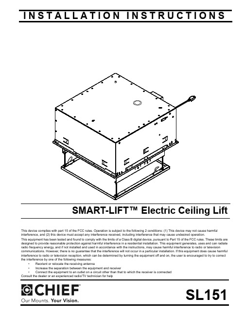
I N S T A L L A T I O N I N S T R U C T I O N SThis device complies with part 15 of the FCC rules. Operation is subject to the following 2 conditions: (1) This device may not cause harmful interference, and (2) this device must accept any interference received, including interference that may cause undesired operation.This equipment has been tested and found to comply with the limits of a Class B digital device, pursuant to Part 15 of the FCC rules. These limits are designed to provide reasonable protection against harmful interference in a residential installation. This equipment generates, uses and can radiate radio frequency energy, and if not installed and used in accordance with the instructions, may cause harmful interference to radio or televisioncommunications. However, there is no guarantee that the interference will not occur in a particular installation. If this equipment does cause harmful interference to radio or television reception, which can be determined by turning the equipment off and on, the user is encouraged to try to correct the interference by one of the following measures:•Reorient or relocate the receiving antenna •Increase the separation between the equipment and receiver •Connect the equipment to an outlet on a circuit other than that to which the receiver is connected Consult the dealer or an experienced radio/TV technician for helpSL151SMART-LIFT™ Electric Ceiling LiftSL151Installation Instructions2DISCLAIMERMilestone AV Technologies, and its affiliated corporations and subsidiaries (collectively, "Milestone"), intend to make thismanual accurate and complete. However, Milestone makes no claim that the information contained herein covers all details,conditions or variations, nor does it provide for every possible contingency in connection with the installation or use of this product. The information contained in this document is subject to change without notice or obligation of any kind. Milestone makes no representation of warranty, expressed or implied,regarding the information contained herein. Milestone assumes no responsibility for accuracy, completeness or sufficiency of the information contained in this document.Chief® is a registered trademark of Milestone AV Technologies.All rights reserved.IMPORTANT SAFETY INSTRUCTIONSWARNING alerts you to the possibility ofserious injury or death if you do not follow the instructions.CAUTIONalerts you to the possibility ofdamage or destruction of equipment if you do not follow thecorresponding instructions.WARNING :FAILURE TO READ ANDFOLLOW THE FOLLOWING INSTRUCTIONS CAN RESULT IN SERIOUS PERSONAL INJURY , DAMAGE TO EQUIPMENTOR VOIDING OF FACTORY WARRANTY . It is the installer’sresponsibility to make sure all components are properly assembled and installed using the instructions provided.IMPORTANT ! :Model SL151 is suitable for use in OtherEnvironmental Air Space in Accordance with Section 300.22(C)of the National Electrical Code.When using an electrical mounting system, basic precautionsshould always be followed, including the following:READ ALL INSTRUCTIONS BEFORE USING THISPRODUCTDANGER:TO REDUCE THE RISK OFELECTRIC SHOCK:1.Always turn off power at source before cleaning.WARNING:TO REDUCE THE RISK OFBURNS, FIRE, ELECTRIC SHOCK, OR INJURY TO PERSONS:•Always turn off power at source before putting on or taking off parts.•Use this mounting system only for its intended use as described in these instructions. Do NOT useattachments not recommended by the manufacturer.•Never operate this mounting system if it has a damaged test cord or test plug. If it is not working properly during testing, return the mounting system to a service center for examination and repair.•Keep the test power cord away from heated surfaces.•Never operate the mounting system with the airopenings blocked. Keep the air openings free of lint,hair, and the like.•Never drop or insert any object into any opening.•Do not use outdoors unless marked for outdoor use.•Route cords and cables as shown in the installation instructions.•To disconnect, turn all controls to the off position, then turn off power at source.WARNING :RISK OF ELECTRIC SHOCK!Connect this mounting system to a properly grounded outlet only. See Grounding Instructions.CAUTION:Changes or modifications to thisunit not expressly approved by the manufacturer can void the units FCC compliance rating and make the unit illegal to operate.WARNING :Failure to provide adequatestructural strength for this component can result in serious personal injury or damage to equipment! It is the installer’s responsibility to make sure the structure to which thiscomponent is attached can support five times the combined weight of all equipment. Reinforce the structure as required before installing the component.WARNING :Exceeding the weight capacitycan result in serious personal injury or damage to equipment! It is the installer’s responsibility to make sure the weight of all components attached to the SL151 does not exceed 35 lbs (15.9 kg).WARNING :RISK OF INJURY! Do not placevideo equipment such as televisions or computer monitors on the ceiling panel of the SL151.NOTE:This system has no user serviceable parts.--SAVE THESE INSTRUCTIONS--Installation Instructions SL1513TOOLS REQUIRED FOR INSTALLATIONPARTSLEGENDTighten FastenerApretar elemento de fijación Befestigungsteil festziehen Apertar fixador Serrare il fissaggio Bevestiging vastdraaien Serrez les fixations Loosen FastenerAflojar elemento de fijación Befestigungsteil lösen Desapertar fixador Allentare il fissaggio Bevestiging losdraaien Desserrez les fixationsPhillips Screwdriver Marcar con lápiz Stiftmarkierung Marcar com lápis Segno a matita Potloodmerkteken Marquage au crayon Adjust Ajustar Einstellen Ajustar Regolare Afstellen AjusterSL151Installation Instructions4DIMENSIONSTABLE OF CONTENTSDisclaimer.....................................................2Tools Required For Installation.................... 3Parts..............................................................3Legend..........................................................3Dimensions...................................................4Installation Requirements..............................5Power Requirements.....................................5Pre-test Lift Before Installation.......................5Power Requirements And Wiring...................5Grounding Instructions.................................. 6Removing Ceiling Panel................................ 6Installing in Ceiling.........................................6-Installing In A Suspended Ceiling...............6-Installing In A Wood Framework (Joists)....7Installing Projector On SL151 (7)Adjustments...................................................7Connecting Control Wiring.............................8Connecting To Power Supply.........................8Wiring Options............................................... 9Re-Attaching Ceiling Panel............................9Table 1: Wiring Table...................................10Table 2: Internal Terminal Descriptions........11Internal/External Wiring TerminalDescriptions (12)Installation Instructions SL1515Figure 25.Place the jumper wire (H) on the external wiring terminal contacts labeled 2and 5, and wire the push button assembly (D) to contacts 1 (red) and 6 (black). (See Figure 3).Figure 36.Plug in the SL151 test cord. (See Figure 2)NOTE:(See Figure 2) for location of external wiring terminal.(See Figure 4) for location of internal wiring terminal.Figure 4Power Requirements and WiringThe SL151 requires 120VAC, 60 Hz and 12 amps power to operate.IMPORTANT ! :This product must be grounded. If it shouldmalfunction or break down, grounding provides a path of least resistance for electric current to reduce the risk of electric shock.Grounding InstructionsThis product is equipped with a test cord having an equipment-grounding conductor and a grounding plug. The plug must be plugged into an appropriate outlet that is properly installed and grounded in accordance with all local codes and ordinances.Wire push button assembly (D) (1-red,6-black)[Some parts not shown for clarity]Internalwiring terminalSL151Installation Instructions6WARNING:RISK OF ELECTROCUTION! All electricalwiring required for installation should be installed by aqualified electrician.WARNING:PINCH HAZARD! FINGERS OR HANDSBETWEEN MOVING PARTS CAN LEAD TO SEVERE PERSONAL INJURY! Keep fingers and hands away from mount when operating.7.Press the push button to test the SL151 while it is still in the pre-test position.•Press when the lift is at its extended position and it willretract.•Press when the lift is at its retracted position and it willextend.•Press while the lift is moving and it will stop.•Leave SL151 in the open position.Removing Ceiling Panel1.Remove and save screws attaching guide wires to ceiling panel. (See Figure 5)Figure 52.Lift up on each corner of ceiling panel to remove pan from clips. (See Figure 6) and (See Figure 7)Figure 6Figure 7INSTALLING IN CEILINGWARNING:IMPROPER INSTALLATION CAN LEAD TOLIFT FALLING CAUSING SEVERE PERSONAL INJURY ORDAMAGE TO EQUIPMENT! It is the installers responsibility to make certain the structure to which the lift is beingmounted is capable of supporting five times the weight of the lift and all attached equipment. Reinforce the structure as required before installing the lift.NOTE:The following instructions assume a suitable mountingstructure and surface exists prior to installation and all power and signal wires and cables have been properly installed.Installing in a Suspended CeilingNOTE:The SL151 may be suspended from three 3/8 in.diameter x 8 in. length (minimum) Grade 2 or better threaded rods (not provided) which are secured to a 1-5/8" x 1-5/8" 12ga metal framing channel (spanning a maximum of 5 feet--not provided) by Grade 2 or better 3/8" channel nuts (not provided).1.Turn SL151 over and place onto threaded rods, inserting the rods into the three slots on top of the SL151 housing.(See Figure 8)2.Secure the threaded rods to the SL151 with Grade 2 or better 3/8 in. jam nuts (not provided) and washers (one of each on inside and one of each on outside-not provided).Figure 8Guide Wire(one on each side)Remove Screw (one on each side)Ceiling PanelGuide WireCeiling PanelClipCeiling Panel RemovedCAUTION:Avoid stressing or bending the lift during installation.e the provided push button (D) to operate the SL151 upand down, ensuring that all clearances are adequate. Installing Projector on SL151NOTE:bracket (a Listed accessory).1.Attach the SLB bracket to the projector following theinstructions included with the bracket.2.Attach the bracket with the projector to the SL151, adjustingleft or right by using the various attachment points in theSL151. (See Figure 10)•Adjust one or the other side of the bracket backward or forward by loosening two screws on each side. (SeeFigure 12)•Adjust bracket as required.•Tighten screws. (See Figure 12)78Unplug the SL151’s test cord (used for testing).Remove the jumper wire and supplied push button wiring (previously installed in the section) from the external terminal block. (See Figure 3)Connect control wiring following instructions included withthe controller and information in Table 1: Wiring Table NOTE:Any knockouts removed in the SL151 must bereplaced with a supplied rubber grommet (G).Feed the video and/or communications cables through theknockout in the rear or top of the lift and connect it to the projector.Ensure there is enough slack in the cables to allow forup and down movement of the lift.Secure cables as necessary using supplied mounting pads (E) and cable ties (B).CAUTION:KEEP SL151 OPEN WHILE PROJECTOR ISRUNNING OR IN COOLING MODE! Premature bulb failure or damage to electrical components may occur if lift closes.NOTE:If SL151 is cycled up and down repeatedly the motor’sthermal overload protection will stop operation.Operation will resume when the thermal overload resets (usually within 3 to 5 minutes).Connecting to Power SupplyIMPORTANT ! :This product must be connected to agrounded metal, permanent wiring system, or an equipment-grounding conductor must be run with the circuit conductors and connected to the equipment-grounding terminal or lead on the product.1.Disconnect and remove power inlet from interior junctionbox.2.Hardwire unit to a 120V 60Hz 12-amp power source.NOTE:This unit was designed to have conduit run directly intothe back of the interior junction box.WARNING:performed by a licensed electricianfollowing all local codes and ordinances.WARNING:DISCONNECT AND TERMINATE POWER LEADS PROPERLY MAY RESULT IN PERSONAL INJURY OR EQUIPMENT DAMAGE!! Licensed electrician must disconnect and terminate the leads to the power cord receptacle, and must hard wire the SL151 to a 12-amp power source.CAUTION:not lined up properly with rectangular holes.Figure 142.Carefully insert clips into rectangular holes in ceiling panel.3.Reattach guide wires (two places) to ceiling panel, usingscrews removed earlier. (See Figure 15)9SL151Installation Instructions10Table 1: WIRING TABLEFigure 16NOTE:The numbers listed in the SL151 Internal and SL151 External columns refer to the corresponding numbers located whereindicated in the wiring pictures. (See Figure 16)EXTERNAL WIRINGINTERNAL WIRINGTable 2: INTERNALTERMINAL DESCRIPTIONS1112Figure 17131415Chief Manufacturing, a products division of Milestone AV Technologies8820-000041 Rev022010 Milestone AV Technologies, a Duchossois Group Company04/10USA/International A8401 Eagle Creek Parkway, Savage, MN 55378P800.582.6480 / 952.894.6280F877.894.6918 / 952.894.6918Europe A Fellenoord 130 5611 ZB EINDHOVEN, The NetherlandsP+31 (0)40 2668620F+31 (0)40 2668615Asia Pacific A Office No. 1 on 12/F, Shatin Galleria18-24 Shan Mei StreetFotan, Shatin, Hong KongP852 2145 4099F852 2145 4477。
功能测试 英文
功能测试英文Function TestFunction testing is an essential part of the software testing process. It involves testing the functions or features of a software application to ensure that they meet the requirements and work as intended. In this article, we will discuss the importance of function testing and the steps involved in conducting it.The purpose of function testing is to verify that all the functions or features of a software application are working correctly. It ensures that the software application meets the specified functional requirements and performs as expected. This type of testing is crucial for identifying any defects or issues in the software, which can be fixed before the application is released to the end users.The first step in function testing is to identify the functions or features that need to be tested. This can be done by reviewing the functional requirements document and understanding the expected behavior of the software application. The functions or features can include user actions, such as clicking a button or entering data, as well as system actions, such as data processing or error handling.Once the functions or features have been identified, test cases need to be created to validate their correctness. A test case is a detailed description of the steps to be executed and the expected results. It should cover all possible scenarios and edge cases to ensure comprehensive testing. The test cases should be designed to test the normal behavior of the functions or features, as well as any error conditions or exceptions that may occur.Next, the test cases need to be executed to validate the functions or features. This can be done manually or using automated testing tools. Manual testing involves following the steps of the test cases and verifying the results. Automated testing, on the other hand, involves writing scripts or using test automation tools to automate the execution of the test cases. This can save time and effort, especially when there are a large number of test cases to be executed.During the execution of the test cases, any defects or issues that are identified should be logged in a defect tracking system. This allows the development team to prioritize and fix the issues. The test cases should be executed multiple times to ensure that the functions or features work consistently and reliably.Once all the test cases have been executed and the functions or features have been validated, a test summary report should be prepared. This report includes information about the test objectives, the test environment, the test results, and any issues or defects identified. It provides a clear overview of the function testing process and the status of the software application.In conclusion, function testing is a critical part of the software testing process. It ensures that all the functions or features of a software application work correctly and meet the specified requirements. By conducting comprehensive function testing, any defects or issues can be identified and fixed before the application is released to the end users.。
基于模型的混合动力电动汽车系统的设计.

2008-01-0085Model-Based Design for Hybrid Electric Vehicle SystemsSaurabh Mahapatra, Tom Egel, Raahul Hassan, Rohit Shenoy, Michael Carone Copyright © 2008 The MathWorks, Inc.ABSTRACTIn this paper, we show how Model-Based Design can be applied in the development of a hybrid electric vehicle system. The paper explains how Model-Based Design begins with defining the design requirements that can be traced throughout the development process. This leads to the development of component models of the physical system, such as the power distribution system and mechanical driveline. We also show the development of an energy management strategy for several modes of operation including the full electric, hybrid, and combustion engine modes. Finally, we show how an integrated environment facilitates the combination of various subsystems and enables engineers to verify that overall performance meets the desired requirements. 1. INTRODUCTIONIn recent years, research in hybrid electric vehicle (HEV) development has focused on various aspects of design, such as component architecture, engine efficiency, reduced fuel emissions, materials for lighter components, power electronics, efficient motors, and high-power density batteries. Increasing fuel economy and minimizing the harmful effects of the automobile on the environment have been the primary motivations driving innovation in these areas.Governmental regulation around the world has become more stringent, requiring lower emissions for automobiles (particularly U.S. EPA Tier 2 Bin 5, followed by Euro 5). Engineers now must create designs that meet those requirements without incurring significant increases in cost. According to the 2007 SAE’s DuPont Engineering survey, automotive engineers feel that cost reduction and fuel efficiency pressures dominate their work life [1] and will continue to play an important role in their future development work.In this paper, we explore key aspects of hybrid electric vehicle design and outline how Model-Based Design can offer an efficient solution to some of the key issues. Due to the limited scope of the paper, we do not expect to solve the problem in totality or offer an optimal design solution. Instead, we offer examples that will illustrateThe MathWorks, Inc.the potential benefits of using Model-Based Design in the engineering workflow. Traditionally, Model-Based Design has been used primarily for controller development.One of the goals of this paper is to show how Model-Based Design can be used throughout the entire system design process.In section 2, we offer a short primer on HEVs and the various aspects of the design. Section 3 is devoted to Model-Based Design and the applicability of the approach to HEV development. Sections 4, 5, and 6 will focus on examples of using Model-Based Design in a typical HEV design.2. HYBRID ELECTRIC VEHICLE DESIGNCONCEPTA block diagram of one possible hybrid electric vehicle architecture is shown in Figure1. The arrows represent possible power flows. Designs can also include a generator that is placed between the power splitter and the battery allowing excess energy to flow back into thebattery.Figure 1: The main components of a hybrid electric vehicle.Conceptually, the hybrid electric vehicle has characteristics of both the electric vehicle and the ICE (Internal Combustion Engine) vehicle. At low speeds, it operates as an electric vehicle with the battery supplying the drive power. At higher speeds, the engine and the battery work together to meet the drive power demand. The sharing and the distribution of power between thesetwo sources are key determinants of fuel efficiency. Note that there are many other possible designs given the many ways that power sources can work together to meet total demand.DESIGN CONSIDERATIONSThe key issues in HEV design [2] are typical of classical engineering problems that involve multilayer, multidomain complexity with tradeoffs. Here, we discuss briefly the key aspects of the component design: very similar to those of a traditional ICE. Engines used in an HEV are typically smaller than that of a conventional vehicle of the same size and the size selected will depend on the total power needs of the vehicle.design are capacity, discharge characteristics and safety. Traditionally, a higher capacity is associated with increase in size and weight. Discharge characteristics determine the dynamic response of electrical components to extract or supply energy to the battery. motors, AC induction motors, or Permanent Magnet Synchronous Motors (PMSM). Each motor has advantages and disadvantages that determine its suitability for a particular application. In this list, the PMSM has the highest power density and the DC motor has the lowest. [3].splitter that allows power flows from the two power sources to the driveshaft. The engine is typically connected to the sun gear while the motor is connected to the ring gear.aerodynamic drag interactions with weight and gradability factors accounted for in the equations.process of the hybrid powertrain is to study the maximum torque demand of the vehicle as a function of the vehicle speed. A typical graph is shown in Figure 2. Ratings of the motor and the engine are determined iteratively to satisfy performance criteria and constraints. The acceleration capabilities are determined by the peak power output of the motor while the engine delivers the power for cruising at rated velocity, assuming that the battery energy is limited. Power sources are coupled to supply power by the power-splitter, and the gear ratio of the power-splitter is determined in tandem. The next steps include developing efficient management strategies for these power sources to optimize fuel economy and designing the controllers. The final steps focus on optimizing the performance of this system under a variety of operating conditions.Figure 2: Maximum torque demand as a function of vehicle tire speed.3. MODEL-BASED DESIGN OF AN HEVMOTIVATIONIn this section, we outline some of the challenges associated with HEV design and explain the motivation for using Model-Based Design as a viable approach for solving this problem.of an HEV design problem is reflected in the large number of variables involved and the complex nonlinear relationships between them. Analytical solutions to this problem require advanced modeling capabilities and robust computational methods.set of requirements to meet the vehicle performance and functionality goals. Requirements refinement proceeds iteratively and depends on implementation costs and equipment availability.conceptualize the operation of the system’s various components and understand the complex interactions between them. This often requires experimentation with various system topologies. For example, studies may include comparing a series configuration with a parallel configuration. Because the goal is a better understanding of the overallsystem behavior, the models must include the appropriate level of detail. system level to a more detailed implementation, engineers elaborate the subsystem models to realize the complete detailed system model. This can be accomplished by replacing each initial model of a component with the detailed model and observing the effects on performance. Completing this process andrealizing a detailed model of the system requires robust algorithms for solving complex mathematics in a timely fashion.and mechanical components. Typically these components are designed by domain specialists. To speed development, these engineers need to effectively communicate and exchange design ideas with a minimum of ambiguity.typical HEV design is to increase the fuel efficiency of the vehicle while maintaining performance demands. Intuitively, one can look at this problem as finding the optimal use of the power sources as a function of the vehicle internal states, inputs, and outputs satisfying various constraints. This translates to the requirement for switching between various operational “power modes” of the vehicle as a func tion of the states, inputs, and measured outputs [4]. In a true environment for Model-Based Design the power management algorithms co-exist with the physical system models.complexity of the various subsystems, HEV controller design is typically a complex task. A variety of control algorithms specific to each subsystem may be required. For example, the controller that manages the frequency of the input voltage to the synchronous motor will be different from the simple control used for torque control of the same motor. Typically, this will manifest itself as a multistage, multiloop control problem. Successful implementation of the controllers requires deployment of these algorithms on processors that are integrated while interfacing with the physical plant. testing ensures that it continues to meet requirements. Detection of errors early in the process helps reduce costs associated with faulty designs. As design errors trickle down the various workflow stages the costs associated with correcting them increase rapidly[5]. The ability to continually verify and validate that requirements are being satisfied isa key aspect of Model-Based Design.A software development environment for Model-Based Design must be able to address the aforementioned challenges. Additionally, a single integrated environment facilitates model sharing between team members. The ability to create models at various levels of abstraction is needed to optimize the simulation time. A mechanism for accelerating the simulation as the complexity increases will also be important. PROCESS OF MODEL-BASED DESIGNModel-Based Design can be thought of as a process of continually elaborating simulation models in order to verify the system performance. The overall goal is to ensure first pass success when building the physicalprototype. Figure 3 shows the key elements of Model-Based Design.The system model forms the “executable specification” that is used to communicate the desired system performance. This model is handed over to the various specialists who use simulation to design and further elaborate the subsystem models. These specialists refine the requirements further by adding details or modifying them. The detailed models are then integrated back into the system level realization piece by piece and verified through simulation. This goes on iteratively until a convergence to an optimal design that best meets the requirements results. During Model-Based Design, C-code generation becomes an essential tool for verifying the system model. The control algorithm model can be automatically converted to code and quickly deployed to the target processor for immediate testing. Code can also be generated for the physical system to accelerate the simulation and/or to test the controller with Hardwarein the Loop simulation.Figure 3: The key elements of Model-Based Design.4. SYSTEM LEVEL MODELING OF AN HEVIn the first stage of the HEV design, the system-level description of the system is realized. Experimentation enables the system designer to explore innovative solutions in the design space resulting in optimal architectures. Our approach has been inspired by an earlier SAE paper [6]. REQUIREMENTSIn the initial stages of the project, it is not uncommon for the specifications of subsystem components to shift. The requirements are in a preliminary form, and are based on previous designs, if available, or best engineering judgment. Requirements are refined when each of the component models is delivered to component designers for additional refinement. There are, however, certain requirements that the system architect understands fully, and can lock down. As the project moves from requirements gathering to specification, the concepts of the system architects can be included in the model. Collaboration between architects and designers leads to a much better and more complete specification. The system can be expressed as a series of separate models that are to be aggregated into an overall system model for testing. Breaking down the model into components facilitates component-based development and allows several teams to work on individual components in parallel. This kind of concurrent development was facilitated by the parallel configuration we chose for our example, in which the electrical and mechanical power sources supply power in parallel. The broad design goals were:Improve fuel efficiency to consume less than 6.5liters per 100 km (L/100 km) for the driver input profile shown in Figure 4.Cover a quarter mile in 25 seconds from rest. Attain a top speed of 193 kph.Figure 4: Driver input profile as outlined in the requirements document.These and other such requirements are typically captured in a requirements document that engineers can associate with the design models. This provides the ability to trace the requirements throughout the model, a key component of Model-Based Design. VEHICLE DYNAMICSModeling the vehicle dynamics can be a challenging task. When creating any simulation model it is important to consider only the effects that are needed to solve the problem at hand. Superfluous details in a model will only slow down the simulation while providing little or noadditional benefit. Because we are primarily interested in the drive cycle performance, we will limit our vehicle model to longitudinal dynamics only. For example, the vehicle was initially modeled as a simple inertial load on a rotating shaft connected to the drive train. ENGINEA complete engine model with a full combustion cycle is also too detailed for this application. Instead, we need a simpler model that provides the torque output for a given throttle command. Using Simulink® and SimDriveLine™, we modeled a 57kW engine with maximum power delivery at 523 radians per second, as shown in Figure5.Figure 5: Engine modeled using blocks from the SimDriveline™ library. SYNCHRONOUS MOTOR/GENERATORThe synchronous motor and generator present an interesting example of electromechanical system modeling. Standard techniques for modeling synchronous machines typically require complex analysis of equations involving electrical and mechanical domains. Because the input source to this machine drive is a DC battery and the output is AC, this would require the creation of complex machine drive and controller designs – often a significant challenge at this stage.An averaged model that mathematically relates the control voltage input with the output torque and resulting speed is a useful alternative. This simplification allows us to focus on the overall behavior of this subsystem without having to worry about the inner workings. Furthermore, we can eliminate the machine drive by simply feeding the DC voltage directly to this subsystem. With this averaged model, we only need a simple Proportional-Integral (PI) controller to ensure effective torque control. TheMotor/Generator subsystem design will be explored in more detail in the next section. POWER-SPLITTERThe power-splitter component is modeled as a simple planetary gear, as shown in Figure 6. With these building blocks, more complex gear topologies can easily be constructed and tested within the overall system model.Figure 6: Power-splitter modeled as a planetary gear with connections.POWER MANAGEMENTThe power management subsystem plays a critical role in fuel efficiency.The subsystem has three main components:• Mode logic that manages the various operatingmodes of the vehicle.• An energy computation block that computes theenergy required to be delivered by the engine, the motor, or both in response to gas pedal input at any given speed.• An engine controller that ensures the engine is theprimary source of power and provides most of the torque. The motor and generator controllers provide torque and speed control.MODE LOGICFor efficient power management, an understanding of the economics of managing the power flow in the system is required. For example, during deceleration, the kinetic energy of the wheels can be partially converted to electrical energy and stored in the batteries. This implies that the system must be able to operate in different modes to allow the most efficient use of the power sources.We used the conceptual framework shown in Figure 7 to visualize the various power management modes.Algorithm design starts with a broad understanding of the various possible operating modes of the system. In our example, we identified four modes—low speed/start, acceleration, cruising, and braking modes. For each of these modes, we determined which of the power sources should be on and which should be off.The conceptual framework of the mode logic is easily implemented as statechart. Statecharts enable the algorithm designer to communicate the logic in an intuitive, readable form.Figure 7: Mode logic conceptualized for the hybrid vehicle.The Stateflow® chart shown in Figure 8 is a realization of the conceptual framework shown in Figure 7. While very similar to the conceptual framework, the Stateflow chart has two notable differences. The “acceleration” and “cruise” states have been grouped to form the “normal” superstate, and the “low speed/start” and “normal” states have been grouped together to form the “motion” superstate. This grou ping helps organize the mode logic into a hierarchical structure that is simpler to visualize and debug.Figure 8: Mode logic modeled with Stateflow®. SYSTEM REALIZATIONAfter the HEV components have been designed, they can be assembled to form the parallel hybrid system shown in Figure9.Figure 9: System-level model of the parallel HEV.This system model can then be simulated to determine if the vehicle meets the desired performance criteria over different drive cycles. As an example, for the input to the system shown in Figure 4, the corresponding speed and the liters per 100 km (L/100 km) outputs are shown in Figure 10. Once the baseline system performance has been evaluated using the system model, we begin the process of model elaboration. In this process, we add more details to the subsystems models to make them more closely represent the actual implementation. During this process, design alternatives can be explored and decisions made based on the analysis results. This is a highly iterative process that is accelerated using Model-Based Design.5. MODEL ELABORATIONIn the model elaboration stage, the subsystem components undergo elaboration in parallel with requirements refinement.A subsystem block is an executable specification because it can be used to verify that the detailed model meets the original set of requirements.As an example, we show how the generator machine drive undergoes requirements refinement and model elaboration. We assume that the engineer responsible for themachine drive design will carry out the model elaboration of the plant and the associated controller.REQUIREMENTS REFINEMENTThe machine drive is an aggregated model of the machine and the power electronics drive. In the system level modeling phase, the key specification is the torque-speed relationship and the power loss. This information was sufficient to define an abstract model to meet the high-level conceptual requirements.Figure 10: Output speed and L/100 km metric for the averaged model.As additional design details are specified, the model must become more detailed to satisfy the subsystem requirements. For example, the generator model will need parameters such as the machine circuit equivalent values for resistance and inductance. Engineers can use this specification as the starting point towards the construction of an electric machine customized for this HEV application.In the case of the generator drive, as the machine model is elaborated from an averaged model to a full three phase synchronous machine implementation, the controller must also be elaborated. PLANT ELABORATIONThe machine model for the synchronous generator is elaborated using SimPowerSystems™ blocks that represent detailed models of power system components and drives. For this model, the electrical and mechanical parts of the machine are each represented by a second-order state-space model. Additionally, the internal flux distribution can be either sinusoidal or trapezoidal. This level of modeling detail is needed to make design decisions as the elaboration process progresses.Figure 11: Detailed PMSM model parameters.The details of this model are captured in the model parameters shown in Figure 11, which specify the effects of internal electrical and magnetic structures.CONTROL ELABORATIONThe controller used in the averaged model of the AC machine drive is a simple PI controller. In model elaboration of the synchronous machine plant, a DC battery source supplies energy to the AC synchronous machine via an inverter circuit that converts DC to AC. These changes in plant model structure and detail require appropriate changes to the controller model to handle different control inputs and implement a new strategy. For example, the power flow to the synchronous machine is controlled by the switching control of the three phase inverter circuit. This added complexity was not present in the initial model of the machine drive because we focused on its behavior rather than its structure. We implemented a sophisticated control strategy, shown in Figure 12, that included cascaded speed and vector controllers [7]. The controllers were developed using Simulink® Control Design™ to satisfy stability and performance requirements.VERIFICATION AND VALIDATIONAt every step of the model elaboration process, the model is verified and validated. Figure 13 shows the averaged and detailed models as they are tested in parallel.Figure 12: Controller elaboration as we move from averaged (top) to detailed (below) model.The test case is a 110 radians per second step input to the machine. The response, shown in Figure 14, reveals comparable performance of both models. This serves as a visual validation that the detailed model is performing as desired. More elaborate testing schemes and formal methods can be devised with test case generation and error detection using assertion blocks from Simulink® Verification and Validation™ [8].Figure 13: Testing of the averaged and the detailed models for speed control with a 1000 rpm step input.SYSTEM INTEGRATIONAfter the component model elaboration and testing is complete, the subsystem containing the averaged model is replaced with the detailed model and the overall system is simulated again.Figure 14: Comparison between the averaged andthe detailed models of the machine drive. This integration will proceed, one component at a time, until the overall system level model contains all the detailed models for each component. This ensures each component is tested and verified in the system model. A single modeling environment for multidomain modeling facilitates the integration. In our example, we used Simulink for this purpose. In Figure 15, we compare the results of the averaged and the detailed models for the driver input profile shown in Figure 4. The detailed model shows deterioration in the speed and L/100 km performance metrics, which can be attributed to the additional detail incorporated into the model.4. CONTROLLER DEPLOYMENTThe electronic control unit (ECU) layout, deployment, and implementation are challenging problems that require innovative thinking. Typically, this requires exploration of the design space to optimize various criteria.Once the design of the system controllers is complete, ECU layout strategy must be considered. In a typical vehicle, we would likely keep some of the controllers inside a centralized ECU, while distributing the others throughout the car.One potential layout would implement the controller for the synchronous motor on a dedicated floating point microcontroller situated closer to the machine, instead of incorporating the controller as part of the centralized ECU. Such a strategy would allow for faster response times from the motor controller for efficient control. If a mix of centralized and distributed controller architecture is under consideration, then the extra layer of complexity introduced by the communication networkshould be accounted for in the modeling.Figure 15: Speed and L/100 km metric comparisons for averaged and detailed models for the HEV. Cost and performance considerations will drive design decisions regarding the selection of floating point or fixed point implementation of each controller. For example, one may consider implementing the controller for the synchronous generator on a fixed-point processor to lower the cost of the overall architecture.6. SIMULATION PERFORMANCEThe final system-level model of the HEV will contain detailed lower-level models of the various components. As model complexity increases, it will take longer to simulate the model in the software environment. This behavior is expected because the model contains more variables, equations, and added components which incur an additional computational cost. Intuitively, this can be visualized as an inverse relationship between simulation performance and complexity of the model as shown in Figure 16.Running the simulations in a high-performance computing environment can offset the increase in simulation times that comes with increased complexity. . With the advent of faster, multicore processors, it is possible to run large simulations without having to investin supercomputer technology.Figure 16: Simulation performance deteriorates with increasing model complexity. We used Simulink simulation modes that employ code generation technology [9] to accelerate the simulation of our model. The improvements in the simulation performance are shown in Figure 17.Figure 17: Comparison of Simulink® simulation modes for the detailed HEV model.CONCLUSIONIn this paper, we first described a typical HEV design and gave an overview of the key challenges. We discussed how the multidomain complications arise from the complex interaction between various mechanical and electrical components—engine, battery, electric machines, controllers, and vehicle mechanics. This complexity, combined with the large number of subsystem parameters, makes HEV design a formidable engineering problem.We chose Model-Based Design as a viable approach for solving the problem because of its numerous advantages, including the use of a single environment for managing multidomain complexity, the facilitation of iterative modeling, and design elaboration. Continuous validation and verification of requirements throughout the design process reduced errors and development time.Our first step in the development process was the realization of a system-level model of the entire HEV. The subsystem components were averaged models, which underwent model elaboration with requirements refinement and modifications in parallel. We showed how statecharts can be used to visualize the operating modes of the vehicle. After each component model was elaborated, we integrated it into the system-level model, compared simulation results of the averaged and detailed models, and noted the effect of model elaboration on the outputs. When simulation times grew long as we moved towards a fully detailed model, we introduced techniques to alleviate this issue. ACKNOWLEDGMENTSThe authors would like to acknowledge the following fellow MathWorks staff who contributed towards the development of the HEV models used in this paper and the writing of this paper. In alphabetical order—Bill Chou, Craig Buhr, Jason Ghidella, Jeff Wendlandt, Jon Friedman, Rebecca Porter, Rick Hyde, and Steve Miller. REFERENCES1. L. Brooke, “Cost remains the boss”, AutomotiveEngineering International, April 2007, SAE International.2. Iqbal Husain, “Electric and Hybrid Vehicles—DesignFundamentals”, 1st E dition, © 2003 CRC Press.3. S J. Chapman, “Electric Machinery Fundamentals”,4th Edition, © 2004 McGraw-Hill Inc.4. Han, Zhang, Yuan, Zhu, Guangyu, Tian andQuanshi, Chen, “Optimal energy management strategy for hybrid electric vehicles”, SAE Paper 2004-01-0576. 5. P. F. Smith, S. Prabhu, and J. Friedman, “Best。
ABB EXCOUNT-I User's Guide

EXCOUNT-I User´s guide2 EXCOUNT-I — User´s Guide | ABB Surge ArrestersSafety informationLegal disclaimerAny responsibility or liability for loss or damage in connection with the use of this product and the accompanying documentation is disclaimed. The information in this document is furnished forinformational use only, is subject to change without notice, may contain errors or inaccuracies, and represents no commitment whatsoever.WARNING!Changes or modifications not expressly approved by the party responsible for compliance could void the user’s authority to operate the ser radiation — avoid direct eye exposure.Class II laser product.Safety instructionsDo not connect the sensor to voltage sources other than a 9-volt Lithium battery with a capacity of minimum 1200mAh. Ensure that the battery is connected correctly.WARNING!All work related to the fitting, mounting, assembly or handling of EXCOUNT-I and the surge arresters should be done with disconnected and earthed conductors. Follow all regulations and rules stated by international or national safety regulations.Normally, the EXCOUNT-I and the surge arresters operate at a high voltage. Therefore theymust be installed in such a way that only qualified personnel has access to them.Table of contentsSection Subject Page Safety information2Table of contents31Introduction41Components guide52Before installation63Using the EXCOUNT-I74Installation95Technical data12ABB Surge Arresters | EXCOUNT-I — User´s Guide 34 EXCOUNT-I — User´s Guide | ABB Surge ArrestersEXCOUNT-I is a surge counter with basic leakage current measurement function. The counter provides a number of unique features such as short-circuit safety and a well-proven electronic display which is easy to read, even in direct sunlight. EXCOUNT-I is specially designed for use with all makes and types of gapless arresters and in diverse environments.This user´s guide covers ABB´s four different models of surge counter EXCOUNT-I. Please follow the instruction for your model.ModelSurge Counting Leakage current measurementAuxiliary contactLaser pointer included1HSA440000-C Yes 1HSA440000-E Yes Yes1HSA440000-J Yes Yes Yes 1HSA440000-LYesYesYes YesKey to the symbolsThis symbol is a visual notice to avoid mistakes which can result in damage of the material and/or no function of the surge arrester monitor EXCOUNT-I.Read the text carefully and if you don’t understand do not proceed.Serious material damage, severe personal injury and/or death can be the result of not following the information given beside this symbol. Read the text carefully and if you don’t understand do not proceed.1. IntroductionABB Surge Arresters | EXCOUNT-I — User´s Guide 51. Components guideFigure 1.1 EXCOUNT-IFigure 1.2 Laser pointer 1HSA440000-J and 1HSA440000-L1Connection from the arrester earth terminal 5Activation diode, total leakage curent measurement 2Connection to earth 6Indication diode 3Solar panel7Laser beam direction 4Display surge counting/leakage current8Button to start the laser beamLaser radiation —avoid direct eye exposure.Class II laser product.2. Before installation2.1 Inspection upon arrivalUpon arrival it is important that the cases are inspected and the contents checked against the packing list which is attached to each case. Any shortage or damage should be reported immediately to the insurance and/or ABB representative and not later than 30 days from the arrival of the goods. ABB cannot take responsibility for shortages or damages not reported within this time period.Verify that the following items are present together with this manual:-EXCOUNT-I-Laser pointer with three batteries (only for 1HSA440 000-J and 1HSA440 000-L)If the contents are to be stored for a long period of time prior to use, they should be kept dry and indoors.2.2 Tools for assemblySpecial instruments or tools are not required for installation of the EXCOUNT-I.2.3 Insert the 9V battery in the EXCOUNT-IFor indoor use a 9V battery should be installed since the power from the solar cells may be too low.To install the battery, open the battery cover using a Philips screwdriver to loosen the two screws. Insert the battery ensuring correct polarity,then replace the battery cover and firmly tighten the screws.The EXCOUNT-I shall be installed in such a way, that the battery cover can be opened.2.4 Insert the batteries in the laser pointer (optional)The laser pointer delivered together with EXCOUNT-I is used for triggering the total leakage current measurement, before using it you’ll need to install all three batteries placed inside the laser pointer box.2.5 Note the counter numberRead and note the counter number before operation of the sensor.6 EXCOUNT-I — User´s Guide | ABB Surge Arresters3. Using the EXCOUNT-I 3.1 Design featuresAs with all surge counters from ABB, EXCOUNT-I does not negatively affect the residual voltage of the arrester thanks to the use of a single turn primary. EXCOUNT-I is housed in a sealed, weather-proof case, suitable for outdoor use and proven to match the short-circuit capability of the arresters. EX-COUNT-I has been designed for highest personal safety and has been successfully short-circuit tested at 65 kA.EXCOUNT-I requires no external power supply as it incorporates its own internal power source in the form of a high-efficiency capacitor charged by solar cells.The electronic display is of Cholesteric Liquid Crystal Display type. This ensures highest readability, even in direct sunlight. The display is Bi-stable, which means that power is only required during refresh of the display.3.2 Surge registrationEXCOUNT-I registers the surge each time the arrester has discharged a current over 10 A. The accumulated number of surges is continuously shown on the electronic display.3.2.1 Auxiliary contact (optional)EXCOUNT-I with auxiliary contact for remote indication (surge count) can be connected to local recording equipment, eg SCADA, provided the connections made are compatible with the below criteria.Version 1HSA440000-E and 1HSA440000-L has a passive normally-open auxiliary contact for remote indication of surge counting. The contact will be closed for approximately 100ms when EXCOUNT-I indicates an impulse count. Connection to the auxiliary contact is made via the 2-wire cable broughtto the outside of the counter. The auxiliary contact is equipped with overvoltage protection. However, when wired for remote indication additional overvoltage protection at the remote end is strongly recom-mended.The auxiliary contact may be fed by either AC or DC source. Maximum voltage shall not exceed values given in the table below.Source Max Voltage Max CurrentAC250 Vrms 1 ArmsDC250 V 1 AABB Surge Arresters | EXCOUNT-I — User´s Guide 73. Using the EXCOUNT-I3.3 Leakage current measurement (optional) The measurement is initiated by triggering a light sensitive diode using the laser pointer. This will initiate EXCOUNT-Ito start measuring the total leakage current for several cycles and shortly thereafter display the average value (in milliamperes). The counter will then automatically return to its normal state after 30 seconds and display number of impulses.When triggering total leakage current measurement with the laser pointer it is recommended that one is standing in front of the surge monitor at a distance no further than 3m, see Figure 3.4.Figure 3.4In addition, an auxiliary relay of suitable type must be connected separately to the EXCOUNT-I auxiliary contact as in the figure 3.3. This auxiliary relay is not included with EXCOUNT-I, as standard. ABB recommended relays listed in the table below should be used to guarantee correct functionality.equipmentFigure 3.3Recommended Auxiliary RelaysVoltage source Relay typeAC / 250 V CR-M 230 AC 2DC / 250 V CR-M 220 DC 2Other voltages: Details upon request8 EXCOUNT-I — User´s Guide | ABB Surge ArrestersABB Surge Arresters | EXCOUNT-I — User´s Guide 94. InstallationSafety informationSerious material damage, severe personal injury and/or death can be the result of not follow-ing this instruction. Therefore, the personnel responsible for the installation of the equipment should read and follow this instruction carefully.Handling and maintenance of all the sensors described in this instruction must be done by personnel trained for this type of work.WARNING!All work related to the installation of EXCOUNT-I and the surge arresters should be made with de-energized and earthed conductors. Follow all regulations and rules stated by international or national safety regulations.Normally, the EXCOUNT-I and the surge arresters operate at a high voltage. Therefore the sensor must be installed in such a way that only qualified personnel has access to it.Battery replacementIf battery is needed, eg. for indoor use, the EXCOUNT-I should be installed in such a way, that the battery cover can be opened.4.1 Installation on structureFor the size of the drilling plan, please refer to dimensions of the EXCOUNT-I in section 5, technical data.If the included M10 bolt does not fit, another bolt with M10 thread can be used. Tightening torque for M10 is 49 Nm.Figure 4.110 EXCOUNT-I — User´s Guide | ABB Surge Arresters4.2 Connection of conductorsThese bolts, nuts and washers are not included. Recommended bolt size M12, use washers, see Figure 4.2.Tightening torque for M12 is 84 NmLength of the conductorsThe length of the conductor between the arrester and the surge counter is to be minimum 0,5m when a clip-on CT is to be used for control measurements of leakage current. The maximum length shall not exceed 3 m in the case of the insulating base and conductor having a LIWV of 15 kV. Longer lengths up to 10m could be used with an insulating base having suitably higher LIWV. The insulated base and conductor shall then be insulated for 5xL kV (LIWV), where L is the conductor length in meters as shown in Figure 4.3.The conductor from the earth terminal of the counter to connection with the grounded support stand (point A in Figure 4.3) on to which the counter is attached (or similar support) shall not exceed 0,5m. For example, Length B as shown in Figure 4.3. The earth conductor may be extended from the con-nection point at the support to any “earth point” if the support itself, due to local requirements, is not considered as sufficiently grounded. However, a flashover of the arrester base may occur if the total length (L+B in Figure 4.3) results in the LIWV as described above being exceeded and the counter maybe damaged if the length B exceeds 0.5m.Connection from the arrester earth terminalConnection to earth4. InstallationFigure 4.2ABB Surge Arresters |EXCOUNT-I — User´s Guide 11Standard ABB insulated base Maximum length L*)1HSA430 000-A, -B 101HSA430 000-C, -D 101HSA430 000-H, -J 101HSA430 000-P3*) On the condition the connecting conductor has at least LIWV = 5xL kV4. InstallationFigure 4.35. Technical dataGeneralClimatic conditions Sealed water-tight design, IP67Short-circuit capability65 kA according to IEC 60099-4Power supply Built-in solar cellsBattery, alternative for indoor use9-volt Lithium battery with a capacity of minimum1200mAh.Surge registration10 AMinimum counting threshold(8/20 microseconds)Surge counting memory capacity999999 registrations (wrap around)Time resolution < 0.5 sLeakage current measurementMeasuring range of total leakage current0.1 — 50 mA peakMeasuring frequency range48 — 62 HzLaser pointerBattery type LR44-L 1.5 V type AlkalineLaser pointer wavelength630 — 680 nm12 EXCOUNT-I — User´s Guide | ABB Surge Arresters5. Technical data EXCOUNT-I versionsEXCOUNT-I can be supplied with an output connection (auxiliary contact) for interfacing to external signalling equipment. A version with only surge counting function are also available.Model SurgeCountingLeakagecurrentmeasurementAuxiliary contact Laser pointerincluded1HSA440000-C Yes1HSA440000-E Yes Yes1HSA440000-J Yes Yes Yes1HSA440000-L Yes Yes Yes YesABB Surge Arresters | EXCOUNT-I — User´s Guide 135. Technical dataPosition of auxiliary contactThe length of the cable is about 50 cm.Figure 5.11HSA440000-E and 1HSA440000L 14 EXCOUNT-I — User´s Guide | ABB Surge Arresters5. Technical dataDimensionsFigure 5.2ABB Surge Arresters | EXCOUNT-I — User´s Guide 15ABB ABHigh Voltage Products Surge ArrestersSE-771 80 Ludvika, Sweden Phone: +46 (0)240 78 20 00 Fax: +46 (0)240 179 83E-Mail: ********************.com /arrestersonline©Copyright 2011 ABB All rights reservedNOTE! ABB AB is working continuously to improve the products. We therefore re-serve the right to change designs, dimen-sions and data without prior notice.Contact usD o c u m e n t 1 H S A 801 080-30e nE X C O U N T -I U s e r ´s G u i d e , E d i t i o n 2, 2011-03。
MODEL TEST 6

MODEL TEST 6Part I VocabularyDirections: There are 20 incomplete sentences in this part. For each sentence there are four choices marked A ), B ), C) and D ). Choose the ONE answer that best completes the sentence. Then mark the corresponding letter on the Answer Sheet with a single line through the center.1. In this school, students are encouraged to develop and express their __ thoughts.A) independent B) correspondent C) distinguished D) peculiar2. He can't speak his own native language well, __ a foreign language.A) let on B) let off C) let down D) let alone3. She has caught a bad cold and it's not __ that she will recover before next Monday.A) unlike B) likely C) possibly D) probably4. Make sure you __ enough time for doing your homework.A) set about B) set up C) set aside D) set apart5. It took me a long time to __ the disappointment of losing the match.A) get through B) get off C) get over D) get down6. Get in the car. There's enough __ for you.A) place B) seat C) spot D) room7. I've had so little __ time recently—I think I've forgotten how to relax.A) empty B) spacious C) spare D) blank8. I wanted to make a bookcase, but I couldn't make __ of the instructions.A) understanding B) sense C) application D) sight9. He could see he was losing the argument, so he said, "I'd rather not __ the matter."A) perform B) prefer C) proceed D) pursue10. The __ of living will only go up. It won't go down.A) price B) value C) cost D) expense11. The fire department ordered that the elevator should __A) be turned off B) be turned downC) be turned up D) be turned out12. I've hardly been ____ since Christmas.A) somewhere B) nowhere C) elsewhere D) anywhere13. Peter's latest book is so good that it is __ all praise.A) for B) on C) beyond D) over14. It is important that you reply without __A) delay B) rest C) pause D) stop15. There are several characteristics of this book __ special attention.A) worthy B) worthy of C) worth of D) worthless16. Neither rain nor snow can stop postmen from ____ letters and parcels.A) spreading B) carrying C) delivering D) transferring17. __ your request, we have already presented it to the committee for consideration.A) In regard to B) In contrast to C) In case of D) In relation to18. The policeman went from house to house, __ whether anyone had seen the missing boy.A) demanding B) inquiring C) requiring D) searching19. ____ , we keep records on all the experiments so that we may have enough data.A) As a whole B) On the average C) As a rule D) By all means20. Don't be so _____ as to believe everything he says.A) intimate B) inclined C) intense D) innocentPart II structureDirections: There are 20 incomplete sentences in this part. For each sentence there are four choices marked A ), B ), C) and D ). Choose the ONE answer that best completes the sentence, Then mark the corresponding letter on the Answer Sheet with a single line through the center.21. We are late. I expect the film __ by the time we get to the cinema.A) will already have startedB) would already have startedC) had already been startedD) has already been started22. No sooner had we sat down ___ we found it was time to go.A) than B) when C) as D) while23. __ tired after hard work, he went to sleep right away.A) Felt B) Feeling C) Being felt D) To feel24. But for his intelligence, we ___ able to achieve it.A) would never have been B) were neverC) had never been D) shall never be25. Only when you have obtained sufficient data, ___ come to a sound conclusion.A) you will B) would you C) you can D) can you26. I'd __ the operation unless it is absolutely necessary.A) not rather have B) rather not haveC) rather not to have D) rather not having27. __ would happen if your father knew you failed?A) What you suppose B) What will you supposeC) What do you suppose D) What you would suppose28. This tape recorder is far __ that one both in quality and in design.A) more superior to B) superior thanC) superior to D) more superior than29. ___ I do it or not is none of your business.A) Whenever B) Whether C) No matter D) Either30. Unfortunately, when I arrived, she ___, so we only had time for a few words.A) just left B) bas just left C) had just left D) was just leaving31. He has ___ heavy a work load that it is difficult for him to find time to travel.A) such B) too C) so D) much32. The piano weighs three hundred pounds, so it is too heavyA) for me to move B) to move by meC) for me not to move D) not to move by me33. Before leaving the country, the old couple sold their house ___ 60,000 dollars.A) at B) for C) on D) with34. Either the college professors or the college president __ responsible for setting the policy.A) is B) are C) has D) have35. The investigation, ___ will soon be published, was made by Professor Smith.A)at which the results B) the results on whichC) whose results D) of whose results36. It is because he is not proud of his achievements __ he is respected by his fellowstudents.A) what B) that C) which D) that is37. It's no use ___ him over. It's too late now.A) to send B) sending C) by sending D)having sent38. I remember ___ once somewhere.A) see him B) to see him C) have seen him D) seeing him39. "I wonder why they are late." "They ___ the train."A) might miss B) may have missedC) could miss D) can have missed40. ___ all necessary preparations for the meeting, it was cancelled.A) Having made B) MakingC) After I have made D) When I had madePart IV Reading ComprehensionDirections: There are 3 passages in this part. Each passage is followed by some questions or unfinished statements. For each of them there are four choices marked A ), B ), C) and D ). You should decide on the best choice and mark the corresponding letter on the Answer Sheet with a single line through the center.Question 41 to 45 are based on the following passageA branch of computer science called artificial intelligence(人工智能)uses programs that help solve problems by using human knowledge and experience. Artificial intelligence systems are also called expertsystems, which enable computers programmed with great amount of information to "think" about many possibilities such as diseases that certain symptoms(症状)could indicate and make a decision for the treatment.Computers are used in teaching as well. Programs that perform computer-aided instruction(CAI计算机辅助教学) are designed to help students at all levels, from elementary school to the university level. The student sits at a computer terminal (终端). The terminal’s screen displays a question for the student to answer. If the answer is wrong or incomplete, the computer may ask the student to try again. It then may supply the correct answer and an explanation. CAI is also used in some adult education programs andas part of the employee-training programs of some business companies.One of the most important uses of computers is to communicate information over long distances. They can send information to each other over telephone lines. As a result, computers keep banks, newspapers, and other institutions supplied with up-to-the-minute information. A computer network consists of many computers in separate rooms, buildings, cities, or countries, all connected together. Computer networks allow people to communicate by using electronic mail(电子邮件)-a document typed into one computer and "sent" to another. Such documents generally travel in only a few minutes, even if they are being sent over a long distance.The computer's ability to share information with other computers over a net-work linked by telephone lines is a major revolution in telecommunications(电讯). The Internet, an international network of computer networks, has spread out since the early 1990's. The Internet began as a US network of scientific and military computers in the 1960's. Now it is an international system for sending and receiving electronic mail, software, and electronic document and picture files all over the world. The Internet has already cut the cost of long-distance communications for many people. In the future it will completely change the way people work. With the Internet, increasing numbers of people can work at home instead of in their office. Computers and their programs are the most complex devices in human history, and probably the most useful. Modern industrial societies now depend on them. As computers become more powerful and widespread, computer education must continue to increase also.41. From the first paragraph we can get to know that ___.A) artificial intelligence systems are beyond scientists' controlB) artificial intelligence systems will take the place of doctorsC) artificial intelligence systems will take the place of scientistsD) artificial intelligence systems are under scientists' control42. If you use E-mail to communicate with your friends, you can ___.A) talk with your friends freelyB) exchange information without paperC) talk with your friends face to faceD) exchange information without computers43. The phrase "up-to-the-minute" in the third paragraph means ___.A) shortest B) latest C) longest D) easiest44. The Internet, according to this passage___.A) was first used in teaching B) was first built by soldiersC) can make us lazy D) can make our lives easier45. What would be the best title for this text?A) Computers Are Dangerous B) Computers Are CleverC) Computers Are Useful D) Computers Are InterestingQuestion 46 to 50 are based on the following passageThe office has always been a place to get ahead. Unfortunately, it is also a place where a lot of natural resources start to fall behind. Take a look around next time you’re at wok. See how many lights are left on when people leave. See how much paper is being wasted. How much electricity is being used to run computers that are left on. Look at how much water is being wasted in the restrooms. And how much solid waste is being thrown out in the rubbish cans. We bet it is a lot.Now, here are some simple ways you produce less waste at work, when you are at the copier, only make the copiers you need. Use both sides of the paper when writing something less important. Turn off the lights when you leave. Use a lower watt bulb in your lamp. Drink your coffee or tea out of your mugs instead of single-use cups. Set up a recycling box for cans and one for bottles. And when you’re in the bathroom brushing your teeth or washing your faces,don’t let the tap run. Remember, if we use fewer resources today, we will save more for tomorrow.46. The main purpose of the passage is to tell people ________A) the disadvantages of working in an officeB) the waste produced in an officeC) to save resources when working in an officeD) how to save water in a restroom47. How many kinds of wastes are mentioned in the passage?A) two B) three C) four D) five48. From the passage we can infer that in the office________A)using computers is a waste of resourceB)many people don’t turn off the computer after using themC)computers are run by electricityD) a computer is not a must for working49. It is suggested that we use both sides of the paper at the copier because_________A) we are short of paper B) the printing is not importantC) we should save paper D) we have to pay for the paper50. The underlined word “mugs” is most likely to be __________A) a machine that makes coffeeB) a container that can be used again and againC) a paper product for teaD) something that can only be found in an officeQuestion 51 to 55 are based on the following passageOne recent study conducted in the United States tested a large number of people. Participants(参加者)included both males and females who range in age from 12 to 83. During the experiment, these people were given a variety of breakfasts, and sometimes they had to skip breakfast completely. Special tests, including blood tests and endurance(忍耐力)tests, were set up to analyze how well the participants’ bodies functioned when they had eaten a certain kind of breakfast.The results showed that if a person eats an adequate breakfast, he or she will work more efficiently and more productively than if he or she skips(随便)breakfast or eats a very poor breakfast. This fact appears to be especially true if a person’s work involves mental activity(脑力工作), The study showed that if school children eat fruit, eggs, bread, and milk before going to school, they will learn more quickly and will be able to concentrate in their lessons for a longer period of time than if their breakfast diet is inadequate.The study also showed that, contrary to what many people believe, if you skip breakfast, you will not lose weight. This is because people become so hungry if they skip breakfast that they eat too much for lunch and end up gaining weight instead of losing. So remember, if you are on a diet, skipping breakfast will not help you. You will probably lose more weight if you reduce your other meals.51. A recent breakfast study tested___A) how different types of people are affected by breakfastB) how different types of breakfast affect peopleC) how males and females of all ages react to a certain kind of breakfastD) how well the participants’ bodies function52.To analyze the functioning of the participants’ bodies, __A)various kinds of breakfasts were given to the participantsB) a well-balanced meal was eatenC)breakfast was altogether skippedD)special tests were set up53. Which of the following is NOT true?A) It’s okay to skip breakfast if your job involves physical activity.B) An inadequate breakfast will result in schoolchildren’s failure to concentrate ontheir lessons for longC) The writer’s view on breakfast is opposite to many other people’sD) A poor breakfast will reduce working efficiency54. The writer suggests that it comes to no good if one ___.A)gains weight B) is on a dietC) skips breakfast D) reduces other meals than breakfast55. If you are on a diet, ____.A) you’d better not eat breakfastB) you must have breakfast and skip lunchC) you’d better reduce your other meals as well as breakfastE)you can have an inadequate breakfastPart V Translation from English into ChineseDirections: In this part there is a passage with 5 underlined parts, numbered 56 to 60. After reading the passage carefully, you should translate the underlined parts into Chinese. Remember to write your translation on the Translation Sheet.A number of studies have suggested that certain people benefit from living with a dog or cat --(56)a pet may help lower blood pressure and heart rate, for example, or ease stress, loneliness.(57)But whether pet owners as a group are a healthier lot has been unclear. The new findings suggest they're not. Using survey data from more than 21,000 young to middle-aged Finnish adults, researchers found that pet owners were generally more likely to be overweight and to view their own health as poor.(58)This was largely because pet owners tended to be middle-aged, have less education and more health-risk factors, explained Dr. Leena K. Koivusilta, the study's lead author. (59)And despite having Fido to take for walks, even dog owners typically got little exercise. This is likely because they were often home-owners who could simply put the dog in the yard, Koivusilta noted."In my opinion," Koivusilta said, (60)"pets provide us all with a vast potential for health promotion, and this has indeed been shown when some special groups have been studied."Pet owners, according to the researchers, may just need to make more of an effort -- such as walking and playing with the dog instead of showing him the way to the yard.Part VI Translation from Chinese into EnglishDirections: In this part there are five sentences, numbered 81 to 85, in Chinese. You are required to translate these sentences into English on the Translation Sheet.61 不论机器多么复杂,它是由简单零件组成的。
ECE_95

ORIGINAL :UNITED NATIONS of July 20, 1995E/ECE/324 )Rev.1/Add.94/Amend.4/Corr.1E/ECE/TRANS/505 )February 21, 2005STATUS OF UNITED NATIONS REGULATIONECE 95UNIFORM PROVISIONS CONCERNING THE APPROVAL OF:VEHICLES WITH REGARD TO THE PROTECTION OF THEOCCUPANTS IN THE EVENT OF A LATERAL COLLISIONIncorporating:00 series of amendments Date of Entry into Force: 06.07.95 Corr. 2 to 00 series of amendments Date of Entry into Force: 10.03.95 01 series of amendments Date of Entry into Force: 12.08.98 Supplement 1 to the 01 series of amendments Date of Entry into Force: 14.11.99 Corr. 1 to the 01 series of amendments Date of Entry into Force: 08.11.00 Corr. 3 to the 00 series of amendments Date of Entry into Force: 26.06.02 02 series of amendments Date of Entry into Force: 16.07.03 Supplement 1 to the 02 series of amendments Date of Entry into Force: 12.08.04ORIGINAL :UNITED NATIONS of July 20, 1995 E/ECE/324)E/ECE/TRANS/505 )Rev.1/Add.94/Amend.4/Corr.1February 21, 2005TITLE:Lateral Collision ProtectionISSUE:3 Regulation No. 95Mar/2005PAGE: IUNITED NATIONS AGREEMENTCONCERNING THE ADOPTION OF UNIFORM TECHNICAL PRESCRIPTIONS FOR WHEELED VEHICLES, EQUIPMENT AND PARTS WHICH CAN BE FITTED AND/OR BE USED ON WHEELED VEHICLES AND THE CONDITIONS FOR RECIPROCAL RECOGNITION OFAPPROVALS GRANTED ON THE BASIS OF THESE PRESCRIPTIONS(*)(Revision 2, including the amendments which entered into force on October 16, 1995)Addendum 94: Regulation No. 95Amendment 4 ErratumUNIFORM PROVISIONS CONCERNING THE APPROVAL OF VEHICLES WITH REGARD TO THEPROTECTION OF THE OCCUPANTS IN THE EVENT OF A LATERAL COLLISION(*)Former title of the Agreement:Agreement Concerning the Adoption of Uniform Conditions of Approval and Reciprocal Recognition of Approval for Motor Vehicle Equipment and Parts, done at Geneva on March 20, 1958.ORIGINAL :UNITED NATIONS of July 20, 1995REGULATION NO. 95UNIFORM PROVISIONS CONCERNING THE APPROVAL OF VEHICLES WITH REGARD TO THE PROTECTION OF THE OCCUPANTS IN THE EVENT OF A LATERAL COLLISIONCONTENTSREGULATION1. Scope2. Definitions3. Application for approval4. Approval5. Specifications and tests6. Modification of the vehicle type7. Conformity of production8. Penalties for non-conformity of production9. Production definitely discontinued10. Transitional provisions11. Names and addresses of technical services responsible for conducting approval tests, and ofadministrative departmentsANNEXESAnnex 1 - Communication concerning the approval or extension or refusal or withdrawal of approval or production definitely discontinued of a vehicle type with regard to protection of occupants inthe event of a lateral collision, pursuant to Regulation No. 95Annex 2 - Arrangements of the approval markAnnex 3 -Procedure for determining the "H" Point and the actual torso angle for seating positions in motor vehiclesAppendix 1 -Description of the three dimensional "H" Point machine (3-D H machine)Appendix 2 -Three dimensional reference systemAppendix 3 -Reference data concerning seating positionsAnnex 4 -Collision test procedureAppendix 1 -Determination of performance dataAppendix 2 -The procedure for calculating the viscous criterion for EUROSID 1 TITLE:Lateral Collision Protection ISSUE:1 Regulation No. 95Oct/2003PAGE: IIORIGINAL :UNITED NATIONS of July 20, 1995REGULATION NO. 95Annex 5 -Mobile deformable barrier characteristicsAppendix 1 - Force-deflection curves for static testsAppendix 2 - Force-deflection curves for dynamic testsAnnex 6 -Technical description of the side impact dummyAnnex 7 -Installation of the side impact dummyAnnex 8 -Partial testTITLE:Lateral Collision Protection ISSUE:1 Regulation No. 95Oct/2003PAGE: IIIORIGINAL :UNITED NATIONS of July 20, 1995REGULATION NO. 951.SCOPEThis Regulation applies to the lateral collision behaviour of the structure of the passengercompartment of M1 and N1 categories of vehicles where the R Point of the lowest seat is notmore than 700 mm from ground level when the vehicle is in the condition corresponding to thereference mass defined in Paragraph 2.10. of this Regulation.2.DEFINITIONSFor the purposes of this Regulation:2.1."Approval of a vehicle" means the approval of a vehicle type with regard to the behaviour ofthe structure of the passenger compartment in a lateral collision;2.2."Vehicle type"means a category of power-driven vehicles which do not differ in suchessential respects as:2.2.1.the length, width and ground clearance of the vehicle, in so far as they have a negative effecton the performance prescribed in this Regulation;2.2.2.the structure, dimensions, lines and materials of the side walls of the passenger compartmentin so far as they have a negative effect on the performance prescribed in this Regulation;2.2.3.the lines and inside dimensions of the passenger compartment and the type of protectivesystems, in so far as they have a negative effect-on the performance prescribed in thisRegulation;2.2.4.the siting of the engine (front, rear or centre);2.2.5.the unladen mass, in so far as there is a negative effect on the performance prescribed in thisRegulation;2.2.6.the optional arrangements or interior fittings in so far as they have a negative effect on theperformance prescribed in this Regulation;2.2.7.the type of front seat(s) and position of the "R" Point in so far as they have a negative effecton the performance prescribed in this Regulation;2.3."Passenger compartment" means the space for occupant accommodation, bounded by theroof, floor, side walls, doors, outside glazing and front bulkhead and the plane of the rearcompartment bulkhead or the plane of the rear-seat back support;2.4."R Point" or "seating reference point" means the reference point specified by the vehiclemanufacturer which:2.4.1.has co-ordinates determined in relation to the vehicle structure;2.4.2.corresponds to the theoretical position of the point of torso/thighs rotation (H Point) for thelowest and most rearward normal driving position or position of use given by the vehiclemanufacturer for each seating position specified by him;TITLE:Lateral Collision Protection ISSUE:1 Regulation No. 95Oct/2003PAGE: 1ORIGINAL :UNITED NATIONS of July 20, 19952.5."H Point" is as established by Annex 3 to this Regulation;2.6."Capacity of the fuel tanks" means the fuel-tank capacity as specified by the manufacturerof the vehicle;2.7."Transverse plane" means a vertical plane perpendicular to the median longitudinal verticalplane of the vehicle;2.8."Protective system" means devices intended to restrain and/or protect the occupants;2.9."Type of protective system" means a category of protective devices which do not differ insuch essential respects as their:technologygeometryconstituent materials;2.10."Reference mass" means the unladen mass of the vehicle increased by a mass of 100 kg(that is the mass of the side impact dummy and its instrumentation);2.11."Unladen mass" means the mass of the vehicle in running order without driver, passengersor load, but with the fuel tank filled to 90% of its capacity and the usual set of tools and sparewheel on board, where applicable;2.12."Mobile deformable barrier" means the apparatus with which the test vehicle is impacted. Itconsists of a trolley and an impactor;2.13."Impactor" means a crushable section mounted on the front of mobile deformable barrier;2.14."Trolley"means a wheeled frame free to travel along its longitudinal axis at the point ofimpact. Its front supports the impactor.3.APPLICATION FOR APPROVAL3.1.The application for approval of a vehicle type with regard to the protection of the occupants inthe event of a lateral collision shall be submitted by the vehicle manufacturer or by his dulyaccredited representative.3.2.It shall be accompanied by the undermentioned documents in triplicate and the followingparticulars:3.2.1. a detailed description of the vehicle type with respect to its structure, dimensions, lines andconstituent materials;3.2.2.photographs and/or diagrams and drawings of the vehicle showing the vehicle type in front,side and rear elevation and design details of the lateral part of the structure;3.2.3.particulars of the vehicle's mass as defined by Paragraph 2.11. of this Regulation;3.2.4.the lines and inside dimensions of the passenger compartment;3.2.5. a description of the relevant side interior fittings and protective systems installed in thevehicle.TITLE:Lateral Collision Protection ISSUE:1 Regulation No. 95Oct/2003PAGE: 2ORIGINAL :UNITED NATIONS of July 20, 1995 TITLE:Lateral Collision ProtectionISSUE:1 Regulation No. 95Oct/2003PAGE: 33.3.The applicant for approval shall be entitled to present any data and results of tests carried out which make it possible to establish that compliance with the requirements can be achieved on prototype vehicles with a sufficient degree of accuracy.3.4. A vehicle which is representative of the type to be approved shall be submitted to the technical service responsible for conducting the approval tests.3.4.1.A vehicle not comprising all the components proper to the type may be accepted for tests provided that it can be shown that the absence of the components omitted has no detrimental effect on the performance prescribed in the requirements of this Regulation.3.4.2. It shall be the responsibility of the applicant for approval to show that the application of Paragraph 3.4.1 is in compliance with the requirements of this Regulation. 4.APPROVAL4.1. If the vehicle type submitted for approval pursuant to this Regulation meets the requirements of Paragraph 5 below, approval of that vehicle type shall be granted.4.2.In case of doubt, account shall be taken, when verifying the conformity of the vehicle to the requirements of this Regulation, of any data or test results provided by the manufacturer which can be taken into consideration in validating the approval test carried out by the technical service.4.3.An approval number shall be assigned to each type approved. Its first two digits (at present 01 corresponding to the 01 series of amendments) shall indicate the series of amendments incorporating the most recent major technical amendments made to the Regulation at the time of issue of the approval. The same Contracting Party may not assign the same approval number to another vehicle type.4.4.Notice of approval or of extension or of refusal of approval of a vehicle type pursuant to this Regulation shall be communicated by the Parties to the Agreement applying this Regulation by means of a form conforming to the model in Annex l to this Regulation and photographs and/or diagrams and drawings supplied by the applicant for approval, in a format not exceeding A4 (210 x 297) mm or folded to that format and on an appropriate scale.4.5.There shall be affixed to every vehicle conforming to a vehicle type approved under this Regulation, conspicuously and in a readily accessible place specified on the approval form, an international approval mark consisting of:4.5.1.a circle surrounding the Letter "E" followed by the distinguishing number of the country whichhas granted approval;(1)(1)1 for Germany,2 for France,3 for Italy,4 for the Netherlands,5 for Sweden,6 for Belgium,7 for Hungary,8 for the Czech Republic,9 for Spain, 10 for Yugoslavia, 11 for the United Kingdom, 12 for Austria, 13 for Luxembourg, 14 for Switzerland, 15 (vacant), 16 for Norway, 17 for Finland, 18 for Denmark, 19 for Romania, 20 for Poland, 21 for Portugal, 22 for the Russian Federation, 23 for Greece, 24 for Ireland, 25 for Croatia, 26 for Slovenia, 27 for Slovakia, 28 for Belarus, 29 for Estonia, 30 (vacant), 31 for Bosnia and Herzegovina, 32 for Latvia, 33 (vacant), 34 for Bulgaria, 35-36 (vacant), 37 for Turkey, 38-39 (vacant), 40 for The former Yugoslav Republic of Macedonia, 41 (vacant), 42 for the European Community (Approvals are granted by its Member States using their respective ECE symbol), 43 for Japan, 44 (vacant), 45 fort Australia and 46 for Ukraine. Subsequent numbers shall be assigned to other countries in the chronological order in which they ratify the Agreement Concerning the Adoption of Uniform Technical Prescriptions for Wheeled Vehicles, Equipment and Parts which can be Fitted and/or be Used on Wheeled Vehicles and the Conditions of for Reciprocal Recognition of Approvals Granted on the Basis of these Prescriptions for Motor Vehicle Equipment and Parts, or in which they accede to that Agreement, and the numbers thus assigned shall be communicated by the Secretary-General of the United Nations to the Contracting Parties to the Agreement.ORIGINAL :UNITED NATIONS of July 20, 1995 TITLE:Lateral Collision ProtectionISSUE:1 Regulation No. 95Oct/2003PAGE: 44.5.2. the number of this Regulation, followed by the Letter "R", a dash and the approval number, to the right of the circle prescribed in Paragraph 4.5.1.4.6.If the vehicle conforms to a vehicle type approved, under one or more other Regulations Annexed to the Agreement, in the country which has granted approval under this Regulation, the symbol prescribed in Paragraph 4.5.1. need not be repeated; in this case the Regulation and approval numbers and the additional symbols of all the Regulations under which approval has been granted in the country which has granted approval under this Regulation shall be placed in vertical columns to the right of the symbol prescribed in Paragraph 4.5.1. 4.7. The approval mark shall be clearly legible and shall be indelible.4.8. The approval mark shall be placed close to or on the vehicle data plate affixed by the manufacturer.4.9. Annex 2 to this Regulation gives examples of approval marks.5.SPECIFICATIONS AND TESTS5.1. The vehicle shall undergo a test in accordance with Annex 4 to this Regulation.5.1.1.The test will be carried out on the driver's side unless asymmetric side structures, if any, are so different as to affect the performance in a side impact. In that case either of the alternatives in Paragraph 5.1.1.1. or 5.1.1.2. may be used by agreement between the manufacturer and test authority.5.1.1.1.The manufacturer will provide the authority responsible for approval with information regarding the compatibility of performances in comparison with the driver's side when the test is being carried out on that side.5.1.1.2. The approval authority, if concerned as to the construction of the vehicle, will decide to have the test performed on the side opposite the driver, this being considered the least favourable. 5.1.2.The Technical Service, after consultation with the manufacturer, may require the test to be carried out with the seat in a position other than the one indicated in Paragraph 5.5.1. ofAnnex 4. This position shall be indicated in the test report.(1)5.1.3.The result of this test shall be considered satisfactory if the conditions set out in Paragraphs 5.2. and 5.3. below are satisfied.(1)Until September 30, 2000, for the purposes of the test requirements, the range of normal longitudinal adjustments shall be limited such that the H-point lies within the length of the door aperture.ORIGINAL :UNITED NATIONS of July 20, 19955.2.Performance criteria5.2.1.The performance criteria, as determined for the collision test in accordance with the Appendixto Annex 4 to this Regulation shall meet the following conditions:5.2.1.1. the head performance criterion (HPC) shall be less than or equal to 1,000; when there is nohead contact, then the HPC shall not be measured or calculated but recorded as "No HeadContact."5.2.1.2. the thorax performance criteria shall be:(a) Rib Deflection Criterion (RDC) less than or equal to 42 mm;(b) Soft Tissue Criterion (VC) less or equal to 1.0 m/sec.For a transitional period of two years after the date specified in Paragraph 10.2. of thisRegulation the V * C value is not a pass/fail criterion for the approval testing, but this valuehas to be recorded in the test report and to be collected by the approval authorities. After thistransitional period, the VC value of 1.0 m/sec shall apply as a pass/fail criterion unless theContracting Parties applying this Regulation decide otherwise.5.2.1.3. the pelvis performance criterion shall be:Pubic Symphysis Peak Force (PSPF) less than or equal to 6 kN.5.2.1.4. the abdomen performance criterion shall be:Abdominal Peak Force (APF) less than or equal to 2.5 kN internal force (equivalent to externalforce of 4.5 kN).5.3.Particular Requirements5.3.1.No door shall open during the test.5.3.2.After the impact, it shall be possible without the use of tools to:5.3.2.1 open a sufficient number of doors provided for normal entry and exit of passengers, and ifnecessary tilt the seat-backs or seats to allow evacuation of all occupants;5 3.2.2. release the dummy from the protective system;5.3.2.3. remove the dummy from the vehicle;5.3.3.no interior device or component shall become detached in such a way as noticeably toincrease the risk of injury from sharp projections or jagged edges;5.3.4.ruptures, resulting from permanent deformation are acceptable, provided these do notincrease the risk of injury;5.3.5.if there is continuous leakage of liquid from the fuel-feed installation after the collision, the rateof leakage shall not exceed 30 g/min; if the liquid from the fuel-feed system mixes with liquidsfrom the other systems and the various liquids cannot easily be separated and identified, allthe liquids collected shall be taken into account in evaluating the continuous leakage. TITLE:Lateral Collision Protection ISSUE:1 Regulation No. 95Oct/2003PAGE: 5ORIGINAL :UNITED NATIONS of July 20, 19956.MODIFICATION OF THE VEHICLE TYPE6.1.Any modification affecting the structure, the number and type of seats, the interior trim orfittings, or the position of the vehicle controls or of mechanical parts which might affect theenergy-absorption capacity of the side of the vehicle, shall be brought to the notice of theadministrative department granting approval. The department may then either:6.1.1.consider that the modifications made are unlikely to have an appreciable adverse effect andthat in any case the vehicle still complies with the requirements, or6.1.2.require a further test report from the technical service responsible for conducting the tests;6.1.2.1. Any modification of the vehicle affecting the general form of the structure of the vehicle or anyvariation in the reference mass greater than 8% which in the judgement of the authority wouldhave a marked influence on the results of the test shall require a repetition of the test asdescribed in Annex 4.6.1.2.2. If the technical service, after consultation with the vehicle manufacturer, considers thatmodifications to a vehicle type are insufficient to warrant a complete retest then a partial testmay be used. This would be the case if the reference mass is not more than 8% differentfrom the original vehicle or the number of front seats is unchanged. Variations of seat type orinterior fittings need not automatically entail a full retest. An example of the approach to thisproblem is given in Annex 8.6.2.Confirmation or refusal of approval, specifying the alteration, shall be communicated by theprocedure specified in Paragraph 4.4. above to the Parties to the Agreement which apply thisRegulation.6.3.The competent authority issuing an extension of approval shall assign a series number toeach communication form drawn up for such an extension.7.CONFORMITY OF PRODUCTIONThe conformity of production procedures shall comply with those set out in the Agreement,Appendix 2 (E/ECE/324-E/ECE/TRANS/505/Rev.2), with the following requirements:7.1.Every vehicle approved under this Regulation shall be so manufactured as to conform to thetype approved by meeting the requirements set out in Paragraph 5 above.7.2.The holder of the approval shall ensure that for each type of vehicle at least the testsconcerning the taking of measurements are carried out.7.3.The authority which has granted type approval may at any time verify the conformity controlmethods applied in each production facility. The normal frequency of these verifications shallbe once every two years.TITLE:Lateral Collision Protection ISSUE:1 Regulation No. 95Oct/2003PAGE: 6ORIGINAL :UNITED NATIONS of July 20, 19958.PENALTIES FOR NON-CONFORMITY OF PRODUCTION8.1.The approval granted in respect of a vehicle type, pursuant to this Regulation, may bewithdrawn if the requirement laid down in Paragraph 7.1. above is not complied with, or if thevehicle or vehicles selected have failed to pass the checks prescribed in Paragraph 7.2.above.8.2.If a Contracting Party to the Agreement applying this Regulation withdraws an approval it haspreviously granted, it shall forthwith so notify the other Contracting Parties applying thisRegulation by means of a communication form conforming to the model in Annex 1 to thisRegulation.9.PRODUCTION DEFINITELY DISCONTINUEDIf the holder of the approval completely ceases to manufacturer a type of vehicle approved inaccordance with this Regulation, he shall so inform the authority which granted theapproval. Upon receiving the relevant communication that authority shall inform thereof theother Parties to the 1958 Agreement applying this Regulation by means of a communicationform conforming to the model in Annex 1 to this Regulation.10. TRANSITIONAL PROVISIONS10.1.As from the official date of entry into force of Supplement 1 to the 02 series of amendments,no Contracting Party applying this Regulation shall refuse to grant ECE approval under thisRegulation as amended by Supplement 1 to the 02 series of amendments.10.2.As from 12 months after the entry into force of the 02 series of amendments ContractingParties applying this Regulation shall grant ECE approvals only to those types of vehicleswhich comply with the requirements of this Regulation as amended by the 02 series ofamendments.10.3.As from 60 months after the entry into service of the 02 series of amendments ContractingParties applying this Regulation may refuse first national registration (first entry into service) ofvehicles which do not meet the requirements of this Regulation as amended by the 02 seriesof amendments.10.4.As from 36 months after the entry into force of Supplement 1 to the 02 series of amendmentsContracting Parties applying this Regulation shall grant ECE approvals only to those types ofvehicles which comply with the requirements of this Regulation, as amended by Supplement 1to the 02 series of amendments.10.5.As from 84 months after the entry into force of Supplement 1 to the 02 series of amendmentsContracting Parties applying this Regulation may refuse first national registration (first entryinto service) of vehicles which do not meet the requirements of this Regulation as amendedby Supplement 1 to the 02 series of amendments.S AND ADDRESSES OF TECHNICAL SERVICES RESPONSIBLE FORCONDUCTING APPROVAL TESTS, AND OF ADMINISTRATIVE DEPARTMENTSThe Contracting Parties to the Agreement applying this Regulation shall communicate to theUnited Nations secretariat the names and addresses of the technical services responsible forconducting approval tests, and of the administrative departments which grant approval and towhich forms certifying approval or extension, or refusal or withdrawal of approval, issued inother countries, are to be sent.TITLE:Lateral Collision Protection ISSUE:2 Regulation No. 95Oct/2004PAGE: 7ORIGINAL :UNITED NATIONS of July 20, 1995TITLE:Lateral Collision Protection ISSUE:2Regulation No. 95 Oct/2004PAGE: 8ANNEX 1(maximum format: A4 (210 x 297 mm))COMMUNICATIONissued by: Name of administration: (1) ............................................................................................................................................................concerning: (2) APPROVAL GRANTEDAPPROVAL EXTENDEDAPPROVAL REFUSEDAPPROVAL WITHDRAWNPRODUCTION DEFINITELY DISCONTINUEDof a vehicle type with regard to protection of occupants in the event of a lateral collision pursuant to Regulation No. 95Approval No. .....Extension No............. l.Trade name or mark of the power-driven vehicle ................................................................................ 2.Vehicle type ......................................................................................................................................... 3.Manufacturer's name and address ...................................................................................................... 4.If applicable name and address of manufacturer's representative ..................................................... 5.Vehicle submitted for approval on ....................................................................................................... 6.Side impact dummy utilized ES-1/ES-2. (2)7.Technical service responsible for conducting approval tests .............................................................. 8.Date of test report ................................................................................................................................ 9.Number of test report .......................................................................................................................... 10. Approval granted/refused/extended/withdrawn. (2) (1)Distinguishing number of the country which has granted/extended/refused/withdrawn approval (see approval provisions in the Regulation).(2)Strike out what does not apply.ORIGINAL :UNITED NATIONS of July 20, 199511. Position of approval mark on the vehicle.............................................................................................12. Place.....................................................................................................................................................13. Date......................................................................................................................................................14. Signature..............................................................................................................................................15. The list of documents deposited with the Administrative Service which has granted approval isAnnexed to this communication and may be obtained on request.TITLE:Lateral Collision Protection ISSUE:2 Regulation No. 95Oct/2004PAGE: 9ÝÑËÒÌÎÇ :E.C.E.© InterRegs Ltd 2004ÑÎ×Ù×ÒßÔ :UNITED NATIONS of July 20, 1995Ì×ÌÔÛæLateral Collision Protection ×ÍÍËÛæ1Regulation No. 95 Oct/2003ÐßÙÛæ 10ANNEX 2ARRANGEMENTS OF THE APPROVAL MARKMODEL AøÍ»» п®¿¹®¿°¸ ìòëò ±º ¬¸·-λ¹«´¿¬·±²÷ ̸» ¿¾±ª» ¿°°®±ª¿´ ³¿®µ ¿ºº·¨»¼ ¬± ¿ ª»¸·½´» -¸±©- ¬¸¿¬ ¬¸» ª»¸·½´» ¬§°» ½±²½»®²»¼ ¸¿-ô ©·¬¸ ®»¹¿®¼ ¬± ¬¸» °®±¬»½¬·±² ±º ¬¸» ±½½«°¿²¬- ·² ¬¸» »ª»²¬ ±º ¿ ´¿¬»®¿´ ½±´´·-·±²ô ¾»»² ¿°°®±ª»¼ ·² ¬¸» Ò»¬¸»®´¿²¼- øÛì÷ °«®-«¿²¬ ¬± λ¹«´¿¬·±² Ò±ò çëò ̸» ¿°°®±ª¿´ ²«³¾»® ·²¼·½¿¬»- ¬¸¿¬ ¬¸» ¿°°®±ª¿´ ©¿- ¹®¿²¬»¼ ·² ¿½½±®¼¿²½» ©·¬¸ ¬¸» ®»¯«·®»³»²¬- ±º λ¹«´¿¬·±² Ò±ò çë ¿- ¿³»²¼»¼ ¾§ ¬¸» ðï -»®·»- ±º ¿³»²¼³»²¬-òMODEL BøÍ»» п®¿¹®¿°¸ ìòêò ±º ¬¸·-λ¹«´¿¬·±²÷̸» ¿¾±ª» ¿°°®±ª¿´ ³¿®µ ¿ºº·¨»¼ ¬± ¿ ª»¸·½´» -¸±©- ¬¸¿¬ ¬¸» ª»¸·½´» ¬§°» ½±²½»®²»¼ ¸¿- ¾»»² ¿°°®±ª»¼ ·² ¬¸» Ò»¬¸»®´¿²¼- øÛì÷ °«®-«¿²¬ ¬± λ¹«´¿¬·±²- Ò±-ò çë ¿²¼ îì (1)øײ ¬¸» ½¿-» ±º ¬¸» ´¿¬¬»® λ¹«´¿¬·±²ô ¬¸» ¿¼¼·¬·±²¿´ -§³¾±´ ©¸·½¸ º±´´±©- ¬¸» λ¹«´¿¬·±² ²«³¾»® ·²¼·½¿¬»- ¬¸¿¬ ¬¸» ½±®®»½¬»¼ ¿¾-±®°¬·±² ½±ó»ºº·½·»²¬ ·- ïòíð ³óï÷ò ̸» º·®-¬ ¬©± ¿°°®±ª¿´ ²«³¾»®- ·²¼·½¿¬» ¬¸¿¬ ¿¬ ¬¸» ¼¿¬» ©¸»² ¬¸» ®»-°»½¬·ª» ¿°°®±ª¿´- ©»®» ¹®¿²¬»¼ô λ¹«´¿¬·±² çë ·²½±®°±®¿¬»¼ ¬¸» ðï -»®·»- ±º ¿³»²¼³»²¬- ¿²¼ λ¹«´¿¬·±² Ò±ò îì ·²½±®°±®¿¬»¼ ¬¸» ðí -»®·»- ±º ¿³»²¼³»²¬-ò øï÷̸» ´¿¬¬»® ²«³¾»® ·- ¹·ª»² ±²´§ ¿- ¿² »¨¿³°´»ò。
EV-TEST100 用户手册说明书

ENGLISH User manualTABLE OF CONTENTS1 PRECAUTIONS AND SAFETY MEASURES (2)1.1 Preliminary instruction (2)2 GENERAL DESCRIPTION (3)3 PREPARATION FOR USE (4)3.1 Initial checks (4)3.2 Adapter power supply (4)3.3 Storage (4)4 NOMENCLATURE (5)4.1 Description of the adapter (5)4.2 Function description of PP STATE selector (6)4.3 Function description of CP STATE selector (6)4.4 Function description of Fault selector (6)5 OPERATING INSTRUCTIONS (7)5.1 Test on EVSE systems (7)5.2 EVSE system Energy meter efficiency check (7)6 MAINTENANCE (8)6.1 Cleaning the adapter (8)6.2 End of life (8)7 TECHNICAL SPECIFICATIONS (8)7.1 Accessories (8)7.1.1 Accessories provided (8)8 ASSISTANCE (9)8.1 Warranty conditions (9)8.2 Assistance (9)1 PRECAUTIONS AND SAFETY MEASURESThe adapter has been designed in compliance with IEC/EN61010-1 guidelines relevant to electronic measuring adapters. For your safety and in order to prevent damaging thethe following instructions:∙ Do not carry out any measurement in humid environments.∙ Do not carry out any measurements in case gas, explosive materials or flammables are present, or in dusty environments.∙ Avoid any contact with the circuit under test if no measurement is in progress.∙ Avoid any contact with exposed metal parts, with unused measuring probes, circuits, etc.∙ Do not carry out any measurement in case you find anomalies in the adapter such as deformation, breaks, substance leaks, absence of display on the screen, etc.∙ Pay special attention when measuring voltages higher than 25V AC, since a risk of electrical shock exists.In this manual, and on the adapter, the following symbols are used:Warning: observe the instructions given in this manual; improper use could damage the adapter or its components.Adapter with double insulationAC VoltageGround reference1.1 PRELIMINARYINSTRUCTION∙ The adapter can be used for AC VOLTAGE measurements on installations with CAT III 300V to ground∙ Do not use the adapter on loads with technical specifications different by the same described in § 7∙ Do not use the adapter if the protection conditions on the circuit are limited or protection devices are damaged. ∙ Do not use the adapter in circuits with voltages and currents higher than the rated ones∙ Do not carry out any measurement in case you find anomalies in the adapter such as deformation, breaks, substance leaks, absence of display on the screen, etc.2 GENERAL DESCRIPTIONThe EV-TEST100 model is an adapter designed to interface with the electric car charging stations’ sockets (EVSE - E lectrical V ehicle S upply E quipment) and perform electrical safety tests on these devices. The adapter is capable of simulating the presence of an electric vehicle in order to measure the output voltage signals from the charging stations as well as fault conditions.EV-TEST100 can be used in combination with the following HT safety testers :Model (*) Construction category FW version MACROTESTEV CAT IV 300V 2.00 (or higher)COMBIG2 COMBIG3COMBIG2PLUS COMBITEST425EVMT-300(*) The list of available models can be changed without notice. In case of doubt contact the after-sales serviceThe adapter has the following features:∙ Use for EVSE stations with charging modes 2 and 3 ∙ Test cable with Type 2 connectors (IEC 62196-2) ∙ Vehicle simulation via Control Pilot system (CP state)∙ Cable current capacity simulation via Proximity Pilot system (PP state) ∙ Fault PE simulation condition∙ Fault condition simulation on the Control Pilot (Fault E)∙ Efficiency check of internal station energy meter (LOAD section) ∙ LED indications for system phase detection ∙ Terminals for connection to HT tester ∙ Protection fuse on LOAD section∙ Test in compliance with IEC/EN61851-1 and IEC/EN60364-7-722 guidelines3 PREPARATION FOR USECHECKS3.1 INITIALBefore shipping, the adapter has been checked from an electric as well as a mechanical point of view. All possible precautions have been taken so that the adapter is delivered free of damage. However, a thorough check of the adapter is recommended in order to detect any damage suffered during transport. In case anomalies are found, immediately contact the forwarding agent. Also check whether the packaging contains all parts indicated in § 7.1.1. In case of discrepancy, please contact the Dealer. Should the adapter be returned, please follow the instructions given in § 8.Should the adapter be used differently from what is specified by themanufacturer, the protection provided may be impaired3.2 ADAPTER POWER SUPPLYThe adapter is powered directly by the charging station via integrated plug cable.3.3 STORAGEIn order to guarantee accurate measurement, after a long storage time, wait for the adapter to come back to normal condition (see § 7).4 NOMENCLATURE4.1DESCRIPTION OF THE ADAPTERCAPTION: 1. Input forconnection to HT instrument via C100EV cable2. Terminals N, PE for connection to HT instrument3. Terminals L1, L2, L3 for connection to HT instrument4. LED for phase presence detection5. PP state selector6. CP state selector7. FAULT PE, FAULT E function selector8. N, PE terminals forexternal load connection 9. LOAD section protection fuse 10. Terminal L for external load connection11. Type 2 plug cable for connection to EVSEFig. 1: Description of the adapter4.2 FUNCTION DESCRIPTION OF PP STATE SELECTORPosition Description NC EVSEdisconnected 13A EVSE connected with maximum current of 13A20A EVSE connected with maximum current of 20A32A EVSE connected with maximum current of 32A63A EVSE connected with maximum current of 63A4.3 FUNCTION DESCRIPTION OF CP STATE SELECTORPosition DescriptionA Electric vehicle disconnectedB Electric vehicle connected, not ready for chargingC Electric vehicle connected, ready for charging, ventilation not requiredD Electric vehicle connected, ready for charging, ventilation required4.4 FUNCTION DESCRIPTION OF FAULT SELECTORPosition Description STATUS OK No fault simulationFAULT PE Fault condition simulation on PE protective conductor (EVSE does not recharge)FAULT E Fault condition simulation on the Control Pilot (EVSE does not recharge)5 OPERATING INSTRUCTIONS5.1 TEST ON EVSE1. Connect the adapter to the In1 input of the HT multifunction instrument using theC100EV supplied cable (see Fig. 1 – part1)2. Connect the L1, PE and N terminals (see Fig. 1 - parts 2, 3 and 4) of the adapterrespectively to B1, B3 and B4 inputs of the HT multifunction tester by using the cables supplied together3. Connect the Type 2 plug cable (see Fig. 1 - part 11) to the EVSE4. Move the PP STATE selector (see Fig. 1 - part 5) to the NC position5. Move the CP STATE selector (see Fig. 1 - part 6) to the A position6. Move the FAULT selector (see Fig. 1 - part 7) to the STATUS OK position7. Select the "EVSE Test" mode on the HT multifunction tester8. Press the GO/STOP button on the HT multifunction tester and follow the guided testprocedure (see the related user manual)For detailed instructions on the use of the adapter, refer to the usermanual of the HT tester to which it must be connectedFig. 2: Use of the adapter for testing EVSE5.2 EFFICIENCY CHECK OF EVSE ENERGY METERThe adapter allows to perform a test in order to evaluate the efficiency of the energy meter inside the EVSE. Consider the following steps:1. Connect an external load with max absorbed current 10A AC to the input terminals L,N, PE (see Fig. 1 - parts 8 and 10) of LOAD section2. Set the three switches to the positions: STATUS OK, C or D (CP STATE), and 13A,20A, 32A or 63A (PP STATE)3. Refer to the instructions of the EVSE under test for the energy meter reading.∙Only skilled and trained technicians should perform maintenance operations. Before carrying out maintenance operations, disconnect allcables from the input terminals.∙Do not use the adapter in environments with high humidity levels or high temperatures6.1 CLEANING THE ADAPTERUse a soft and dry cloth to clean the adapter. Never use wet cloths, solvents, water, etc.END OF LIFECAUTION: the symbol on the adapter indicates that the appliance and itsaccessories must be collected separately and correctly disposed of.7 TECHNICAL SPECIFICATIONSInput voltage: max 415V AC Phase-Phase, 50/60Hz ±5% Connection to EVSE: integrated cable with Type 2 plug, length 60cm Recharging stations: charging modes 2 and 3PP Simulation: NC,13A, 20A, 32A, 63ACP Simulation: status A, B, C, D, ventilation/not ventilation Simulation EVSE fault: Fault PE, Fault ECP output signal: PWM communication protocol, 12VAllowed output load: 240V, 50/60Hz, max 10A ACProtection fuse: Fast type 250V/10A (5x20mm) (0.2x0.8in)Safety: IEC/EN61010-1 Reference guidelines: IEC/EN61851-1, IEC/EN60364-7-722Insulation: doubleinsulation Measurement category: CAT III 300VPollution degree: 2Dimensions (L x W x H): 210 x 115 x 60mm (8 x 5 x 2in)Weight (with integrated cable): 900g (32ounces)Mechanical protection: IP40Working temperature: 0°C ÷ 40°C (32°F ÷ 104°F)Working humidity: <80%RHStorage temperature: -10°C ÷ 60°C (14°F ÷ 140°F)Storage humidity: <80%RHMax operating altitude: 2000m (6562ft)This adapter complies with requirements of Low Voltage Directive 2014/35/EU (LVD) This adapter complies with requirements of European Directive 2011/65/EU (RoHS)and 2012/19/EU (WEEE)7.1 ACCESSORIES7.1.1 Accessories provided∙Cable for connection to HT tester Code C100EV∙ Carrying case∙ User manual8.1 WARRANTYCONDITIONSThis adapter is warranted against any material or manufacturing defect, in compliance with the general sales conditions. During the warranty period, defective parts may be replaced. However, the manufacturer reserves the right to repair or replace the product. Should the adapter be returned to the After-sales Service or to a Dealer, transport will be at the Customer's charge. However, shipment will be agreed in advance. A report will always be enclosed to a shipment, stating the reasons for the product's return. Only use original packaging for shipment. Any damage due to the use of non-original packaging material will be charged to the Customer. The manufacturer declines any responsibility for injury to people or damage to property.The warranty shall not apply in the following cases:∙Repair and/or replacement of accessories and battery (not covered by warranty).∙Repairs that may become necessary as a consequence of an incorrect use of the adapter or due to its use together with non-compatible appliances.∙Repairs that may become necessary as a consequence of improper packaging.∙Repairs which may become necessary as a consequence of interventions performed by unauthorized personnel.∙ Modifications to the adapter performed without the manufacturer's explicit authorization.∙Use not provided for in the adapter's specifications or in the instruction manual.The content of this manual cannot be reproduced in any form without the manufacturer's authorization.Our products are patented and our trademarks are registered. The manufacturer reserves the right to make changes in the specifications and prices if required by improvements in technology.8.2 ASSISTANCEIf the adapter does not operate properly, before contacting the After-sales Service, please check the conditions. Should the adapter still operate improperly, check that the product is operated according to the instructions given in this manual. Should the adapter be returned to the After-sales Service or to a Dealer, transport will be at the Customer's charge. However, shipment will be agreed in advance. A report will always be enclosed to a shipment, stating the reasons for the product's return. Only use original packaging for shipment. Any damage due to the use of non-original packaging material will be charged to the Customer.。
ECE R10.03

E/ECE/324 )Add.9/Rev.3E/ECE/TRANS/505 )August 14, 2008STATUS OF UNITED NATIONS REGULATIONECE 10-03UNIFORM PROVISIONS CONCERNING THE APPROVAL OF:VEHICLES WITH REGARD TO ELECTROMAGNETIC COMPATIBILITY Incorporating:02 series of amendments Date of Entry into Force: 03.09.97 Corr. 1 to the 02 series of amendments Dated: 11.03.98Supplement 1 to the 02 series of amendments Date of Entry into Force: 04.02.99 Corr. 2 to the 02 series of amendments Dated: 10.11.99Supplement 2 to the 02 series of amendments Date of Entry into Force: 12.08.04 03 series of amendments: Date of Entry into Force: 11.07.08E/ECE/324 )Add.9/Rev.3E/ECE/TRANS/505 )August 14, 2008UNITED NATIONSAGREEMENTCONCERNING THE ADOPTION OF UNIFORM TECHNICAL PRESCRIPTIONS FOR WHEELED VEHICLES, EQUIPMENT AND PARTS WHICH CAN BE FITTED AND/OR BE USED ON WHEELED VEHICLES AND THE CONDITIONS FOR RECIPROCAL RECOGNITION OF APPROVALS GRANTED ON THE BASIS OF THESE PRESCRIPTIONS (*)(Revision 2, including the amendments which entered into force on October 16, 1995)Addendum 9: Regulation No. 10Revision 3Incorporating all valid text up to:Supplement 2 to the 02 series of amendments − Date of entry into force: August 12, 200403 series of amendments: Date of entry into force: July 11, 2008UNIFORM PROVISIONS CONCERNING THE APPROVAL OF VEHICLES WITHREGARD TO ELECTROMAGNETIC COMPATIBILITY(*)Former title of the Agreement:Agreement Concerning the Adoption of Uniform Conditions of Approval and Reciprocal Recognition of Approval for Motor Vehicle Equipment and Parts, done at Geneva on March 20, 1958.REGULATION NO. 10UNIFORM PROVISIONS CONCERNING THE APPROVAL OF VEHICLESWITH REGARD TO ELECTROMAGNETIC COMPATIBILITYCONTENTSREGULATION1. Scope2. Definitions3. Application for approval4. Approval5. Markings6. Specifications7. Amendment or extension of a vehicle type approval following electrical/electronic sub assembly(ESA) addition or substitution8. Conformity of production9. Penalties for non-conformity of production10. Production definitely discontinued11. Modification and extension of type approval of a vehicle or ESAprovisions12. Transitional13. Names and addresses of Technical Services conducting approval tests, and of AdministrativeDepartmentsANNEXESAnnex 1:Examples of approval marksAnnex 2A:Model of information document for type approval of a vehicle, with respect to electromagnetic compatibilityAnnex 2B:Model of information document for type approval of an electric/electronic sub assembly, with respect to electromagnetic compatibilityAnnex 3A:Model of communication form for vehicle type approvalAnnex 3B:Model of communication form for type approval of electrical/electronic sub-assemblies Annex 3C:Attestation with regard to Paragraph 3.2.9.Annex 4:Method of measurement of radiated broadband electromagnetic emissions from vehicles Annex 5:Method of measurement of radiated narrowband electromagnetic emissions from vehiclesAnnex 6:Method of testing for immunity of vehicles to electromagnetic radiationAnnex 7:Method of measurement of radiated broadband electromagnetic emissions from electrical/electronic sub-assembliesAnnex 8:Method of measurement of radiated narrowband electromagnetic emissions from electrical/electronic sub-assembliesAnnex 9:Method(s) of testing for immunity of electrical/electronic sub-assemblies to electromagnetic radiationAnnex 10:Method(s) of testing for immunity to and emission of transients of electrical/electronic sub-assemblies1. SCOPEThis Regulation applies to:1.1.vehicles of Categories L, M, N and O (1) with regard to electromagnetic compatibility;ponents and separate technical units intended to be fitted in these vehicles with thelimitation given in Paragraph 3.2.1. with regard to electromagnetic compatibility.Itcovers:(a) requirements regarding the immunity to radiated and conducted disturbances forfunctions related to direct control of the vehicle, related to driver, passenger and otherroad users' protection and related to disturbances, which would cause confusion tothe driver or other road users;(b) requirements regarding the control of unwanted radiated and conducted emissions toprotect the intended use of electrical or electronic equipment at own or adjacentvehicles or nearby, and the control of disturbances from accessories that may beretrofitted to the vehicle.2. DEFINITIONSFor the purposes of this Regulation:2.1."Electromagnetic compatibility" means the ability of a vehicle or component(s) orseparate technical unit(s) to function satisfactorily in its electromagnetic environment withoutintroducing intolerable electromagnetic disturbances to anything in that environment.2.2."Electromagnetic disturbance" means any electromagnetic phenomenon which maydegrade the performance of a vehicle or component(s) or separate technical unit(s), or ofany other device, unit of equipment or system operated in vicinity of a vehicle. Anelectromagnetic disturbance may be electromagnetic noise, an unwanted signal or a changein the propagation medium itself.2.3."Electromagnetic immunity" means the ability of a vehicle or component(s) or separatetechnical unit(s) to operate without degradation of performance in the presence of(specified) electromagnetic disturbances which includes wanted radio frequency signalsfrom radio transmitters or radiated in-band emissions of industrial-scientific-medical (ISM)apparatus, internal or external to the vehicle.2.4."Electromagnetic environment" means the totality of electromagnetic phenomena existingat a given location.2.5."Broadband emission" means an emission, which has a bandwidth greater than that of aparticular measuring apparatus or receiver (International Special Committee on RadioInterference (CISPR) 25, second edition).2.6."Narrowband emission" means an emission which has a bandwidth less than that of aparticular measuring apparatus or receiver (CISPR 25, second edition).(1)As defined in Annex 7 to the Consolidated resolution on the Construction of Vehicles (R.E.3), (document TRANS/WP.29/Rev.1/Amend .2, as last amended by Amend.4).2.7."Electrical/electronic system" means (an) electrical and/or electronic device(s) or set(s) ofdevices together with any associated electrical connections which form part of a vehicle butwhich are not intended to be type approved separately from the vehicle.2.8."Electrical/electronic sub-assembly" (ESA) means an electrical and/or electronic deviceor set(s) of devices intended to be part of a vehicle, together with any associated electricalconnections and wiring, which performs one or more specialized functions. An ESA may beapproved at the request of a manufacturer or his authorized representative as either a"component" or a "separate technical unit (STU)".2.9."Vehicle type" in relation to electromagnetic compatibility includes all vehicles, which donot differ essentially in such respects as:2.9.1.the overall size and shape of the engine compartment;2.9.2.the general arrangement of the electrical and/or electronic components and the generalwiring arrangement;2.9.3.the primary material of which the body or shell of the vehicle is constructed (for example, asteel, aluminium or fiberglass body shell). The presence of panels of different material doesnot change the vehicle type provided the primary material of the body is unchanged.However, such variations must be notified."ESA type" in relation to electromagnetic compatibility means ESAs, which do not differ 2.10. Anin such essential respects as:2.10.1.the function performed by the ESA;2.10.2.the general arrangement of the electrical and/or electronic components, if applicable.2.11."Vehicle wiring harness" means supply voltage, bus system (e.g. CAN), signal or activeantenna cables, which are installed by the vehicle manufacturer.2.12."Immunity related functions" are:(a) Functions related to the direct control of the vehicle:(i) by degradation or change in: e.g. engine, gear, brake, suspension, activesteering, speed limitation devices;(ii) by affecting drivers position: e.g. seat or steering wheel positioning;(iii) by affecting driver's visibility: e.g. dipped beam, windscreen wiper.(b) Functions related to driver, passenger and other road user protection:(i) e.g. airbag and safety restraint systems.(c) Functions which when disturbed cause confusion to the driver or other road users:(i) optical disturbances: incorrect operation of e.g. direction indicators, stop lamps,end outline marker lamps, rear position lamp, light bars for emergency system,wrong information from warning indicators, lamps or displays related tofunctions in subparagraphs (a) or (b) which might be observed in the directview of the driver;(ii) acoustical disturbances: incorrect operation of e.g. anti-theft alarm, horn.(d) Functions related to vehicle data bus functionality:(i) by blocking data transmission on vehicle data bus-systems, which are used totransmit data, required to ensure the correct functioning of other immunityrelated functions.(e) Functions which when disturbed affect vehicle statutory data: e.g. tachograph,odometer.3. APPLICATION FOR APPROVAL3.1. Approval of a Vehicle Type3.1.1.The application for approval of a vehicle type, with regard to its electromagneticcompatibility, shall be submitted by the vehicle manufacturer.3.1.2. A model of information document is shown in Annex 2A.3.1.3.The vehicle manufacturer shall draw up a schedule describing all relevant vehicleelectrical/electronic systems or ESAs, body styles, variations in body material, generalwiring arrangements, engine variations, left-hand/right-hand drive versions and wheelbaseversions. Relevant vehicle electrical/electronic systems or ESAs are those which may emitsignificant broadband or narrowband radiation and/or those which are involved in immunityrelated functions of the vehicle (see Paragraph 2.12.).3.1.4. A vehicle representative of the type to be approved shall be selected from this schedule bymutual agreement between the manufacturer and the Competent Authority. The choice ofvehicle shall be based on the electrical/electronic systems offered by the manufacturer.One or more vehicles may be selected from this schedule if it is considered by mutualagreement between the manufacturer and the Competent Authority that differentelectrical/electronic systems are included which are likely to have a significant effect on thevehicle's electromagnetic compatibility compared with the first representative vehicle.3.1.5.The choice of the vehicle(s) in conformity with Paragraph 3.1.4. above shall be limited tovehicle/electrical/electronic system combinations intended for actual production.3.1.6.The manufacturer may supplement the application with a report on tests which have beencarried out. Any such data provided may be used by the approval authority for the purposeof drawing up the communication form for type-approval.3.1.7.If the Technical Service responsible for the type approval test carries out the test itself, thena vehicle representative of the type to be approved according to Paragraph 3.1.4. shall beprovided.3.1.8.For vehicles of Categories M, N, and O the vehicle manufacturer must provide a statementof frequency bands, power levels, antenna positions and installation provisions for theinstallation of radio frequency transmitters (RF-transmitters), even if the vehicle is notequipped with an RF transmitter at time of type approval. This should cover all mobile radioservices normally used in vehicles. This information must be made publicly availablefollowing the type approval.Vehicle manufacturers must provide evidence that vehicle performance is not adverselyaffected by such transmitter installations.3.2. ESA type Approval3.2.1.Applicability of this Regulation to ESA:3.2.2.The application for approval of a type of ESA with regard to its electromagnetic compatibilityshall be submitted by the vehicle manufacturer or by the manufacturer of the ESA.3.2.3. A model of information document is shown in Annex 2B.3.2.4.The manufacturer may supplement the application with a report on tests which have beencarried out. Any such data provided may be used by the approval authority for the purposeof drawing up the communication form for type-approval.3.2.5.If the Technical Service responsible for the type approval test carries out the test itself, thena sample of the ESA system representative of the type to be approved shall be provided, ifnecessary, after discussion with the manufacturer on, e.g., possible variations in the layout,number of components, number of sensors. If the Technical Service deems it necessary, itmay select a further sample.3.2.6.The sample(s) must be clearly and indelibly marked with the manufacturer's trade name ormark and the type designation.3.2.7.Where applicable, any restrictions on use should be identified. Any such restrictions shouldbe included in Annexes 2B and/or 3B.3.2.8.ESA which are brought to the market as spare parts need no type approval if they areobviously marked as a spare part by an identification number and if they are identical andfrom the same manufacturer as the corresponding original equipment manufacturer (OEM)part for an already type approved vehicle.ponents sold as aftermarket equipment and intended for the installation in motorvehicles need no type approval if they are not related to immunity related functions(see Paragraph 2.12.). In this case a declaration must be issued by the manufacturer thatthe ESA fulfils the requirements of this Regulation and in particular the limits defined inParagraphs 6.5., 6.6., 6.8. and 6.9.During the transition period, ending on November 4, 2008, the person or legal entityresponsible for placing on the market of such a product has to submit all relevantinformation and/or a sample to a Technical Service which will determine if the equipment isimmunity related or not. The result of the inspection shall be available within three weeksand not require additional testing. A document according to the example given in Annex 3Cshall be issued by the Technical Service within the same period. In case of doubts and ifthe Technical Service refuses to issue an attestation according to Annex 3C, themanufacturer has to apply for type approval for his product.4. APPROVAL4.1. Type Approval Procedures4.1.1. Type Approval of a VehicleThe following alternative procedures for vehicle type approval may be used at the discretionof the vehicle manufacturer.4.1.1.1. Approval of a Vehicle InstallationA vehicle installation may be type approved directly by following the provisions laid down inParagraph 6 of this Regulation. If this procedure is chosen by a vehicle manufacturer, noseparate testing of electrical/electronic systems or ESAs is required.4.1.1.2. Approval of Vehicle Type by Testing of Individual ESAsA vehicle manufacturer may obtain approval for the vehicle by demonstrating to theapproval authority that all the relevant (see Para. 3.1.3. of this Regulation)electrical/electronic systems or ESAs have been approved in accordance with thisRegulation and have been installed in accordance with any conditions attached thereto.4.1.1.3. A manufacturer may obtain approval according to this Regulation if the vehicle has noequipment of the type, which is subject to immunity or emission tests. Such approvals donot require testing.4.1.2. Type Approval of an ESAType approval may be granted to an ESA to be fitted either to any vehicle type (componentapproval) or to a specific vehicle type or types requested by the ESA manufacturer(separate technical unit approval).4.1.3.ESAs, which are intentional RF transmitters, which have not received type approval inconjunction with a vehicle manufacturer, must be supplied with suitable installationguidelines.4.2. Granting of Type Approval4.2.1. Vehicle4.2.1.1. If the representative vehicle fulfils the requirements of Paragraph 6 of this Regulation, typeapproval shall be granted.4.2.1.2. A model of communication form for type approval is contained in Annex 3A.4.2.2. ESA4.2.2.1. If the representative ESA system(s) fulfil(s) the requirements of Paragraph 6 of thisRegulation, type approval shall be granted.4.2.2.2. A model of communication form for type approval is contained in Annex 3B.4.2.3.In order to draw up the communication forms referred to in Paragraph 4.2.1.2. or 4.2.2.2.above, the Competent Authority of the Contracting Party granting the approval may use areport prepared or approved by a recognized laboratory or in accordance with the provisionsof this Regulation.4.3.Approval, or refusal of approval, of a type of vehicle or ESA in accordance with thisRegulation shall be notified to the Parties to the Agreement applying this Regulation on aform conforming to the model in Annex 3A or 3B of this Regulation, accompanied byphotographs and/or diagrams or drawings on an appropriate scale supplied by the applicantin a format not larger than A4 (210 x 297 mm) or folded to those dimensions.5. MARKINGS5.1.An approval number shall be assigned to each vehicle or ESA type approved. The first twodigits of this number (at present 03) shall indicate the series of amendments correspondingto the most recent essential technical amendments made to the Regulation at the date ofapproval. A Contracting Party may not assign the same approval number to another type ofvehicle or ESA.Markings5.2. Presenceof5.2.1. VehicleAn approval mark described in Paragraph 5.3. below shall be affixed to every vehicleconforming to a type approved under this Regulation.5.2.2. Sub-assemblyAn approval mark described in Paragraph 5.3. below shall be affixed to every ESAconforming to a type approved under this Regulation.No marking is required for electrical/electronic systems built into vehicles which areapproved as units.5.3.An international approval mark must be affixed, in a conspicuous and easily accessibleplace specified on the approval communication form, on each vehicle conforming to the typeapproved under this Regulation. This mark shall comprise:5.3.1. A circle containing the letter "E", followed by the distinguishing number of the countrygranting the approval. (1)5.3.2.The number of this Regulation, followed by the letter "R", a dash and the approval numberto the right of the circle specified in Paragraph 5.3.1.5.4.An example of the type-approval mark is shown in Annex 1 to this Regulation.5.5.Markings on ESAs in conformity with Paragraph 5.3. above need not be visible when theESA is installed in the vehicle.6. SPECIFICATIONSSpecifications6.1. General6.1.1. A vehicle and its electrical/electronic system(s) or ESA(s) shall be so designed, constructedand fitted as to enable the vehicle, in normal conditions of use, to comply with therequirements of this Regulation.6.1.1.1. A vehicle shall be tested for radiated emissions and for immunity to radiated disturbances.No tests for conducted emissions or immunity to conducted disturbances are required forvehicle type approval.6.1.1.2. ESA(s) shall be tested for radiated and conducted emissions, for immunity to radiated andconducted disturbances.6.1.2.Before testing the Technical Service has to prepare a test plan in conjunction with themanufacturer, which contains at least mode of operation, stimulated function(s), monitoredfunction(s), pass/fail criterion(criteria) and intended emissions.(1)1 for Germany,2 for France,3 for Italy,4 for the Netherlands,5 for Sweden,6 for Belgium,7 for Hungary,8 for the CzechRepublic, 9 for Spain, 10 for Serbia, 11 for the United Kingdom, 12 for Austria, 13 for Luxembourg, 14 for Switzerland,15 (vacant), 16 for Norway, 17 for Finland, 18 for Denmark, 19 for Romania, 20 for Poland, 21 for Portugal, 22 for theRussian Federation, 23 for Greece, 24 for Ireland, 25 for Croatia, 26 for Slovenia, 27 for Slovakia, 28 for Belarus, 29 for Estonia, 30 (vacant), 31 for Bosnia and Herzegovina, 32 for Latvia, 33 (vacant), 34 for Bulgaria, 35 (vacant), 36 for Lithuania,37 for Turkey, 38 (vacant), 39 for Azerbaijan, 40 for The former Yugoslav Republic of Macedonia, 41 (vacant), 42 for theEuropean Community (Approvals are granted by its Member States using their respective ECE symbol), 43 for Japan,44 (vacant), 45 for Australia, 46 for Ukraine, 47 for South Africa, 48 for New Zealand, 49 for Cyprus, 50 for Malta, 51 for theRepublic of Korea, 52 for Malaysia, 53 for Thailand, 54 and 55 (vacant), 56 for Montenegro, 57 (vacant) and 58 for Tunisia.Subsequent numbers shall be assigned to other countries in the chronological order in which they ratify or accede to the Agreement Concerning the Adoption of Uniform Technical Prescriptions for Wheeled Vehicles, Equipment and Parts which can be Fitted and/or be Used on Wheeled Vehicles and the Conditions for Reciprocal Recognition of Approvals Granted on the Basis of these Prescriptions, and the numbers thus assigned shall be communicated by the Secretary-General of the United Nations to the Contracting Parties to the Agreement.6.2. Specifications Concerning Broadband Electromagnetic Radiation from Vehicles6.2.1. Method of MeasurementThe electromagnetic radiation generated by the vehicle representative of its type shall bemeasured using the method described in Annex 4. The method of measurement shall bedefined by the vehicle manufacturer in accordance with the Technical Service.6.2.2. Vehicle Broadband Type Approval Limits6.2.2.1. If measurements are made using the method described in Annex 4 using avehicle-to-antenna spacing of 10.0 ± 0.2 m, the limits shall be 32 dB microvolts/m in the30 to 75 MHz frequency band and 32 to 43 dB microvolts/m in the 75 to 400 MHz frequencyband, this limit increasing logarithmically with frequencies above 75 MHz as shownin Appendix 2. In the 400 to 1,000 MHz frequency band the limit remains constant at43 dB microvolts/m.6.2.2.2. If measurements are made using the method described in Annex 4 using avehicle-to-antenna spacing of 3.0 ± 0.05 m, the limits shall be 42 dB microvolts/m in the30 to 75 MHz frequency band and 42 to 53 dB microvolts/m in the 75 to 400 MHz frequencyband, this limit increasing logarithmically with frequencies above 75 MHz as shown inAppendix 3. In the 400 to 1,000 MHz frequency band the limit remains constant at53 dB microvolts/m.6.2.2.3. On the vehicle representative of its type, the measured values, expressed indB microvolts/m shall be below the type approval limits.6.3. Specifications Concerning Narrowband Electromagnetic Radiation from Vehicles6.3.1. Method of MeasurementThe electromagnetic radiation generated by the vehicle representative of its type shall bemeasured using the method described in Annex 5. These shall be defined by the vehiclemanufacturer in accordance with the Technical Service.Narrowband Type Approval Limits6.3.2. Vehicle6.3.2.1. If measurements are made using the method described in Annex 5 using avehicle-to-antenna spacing of 10.0 ± 0.2 m, the limits shall be 22 dB microvolts/m in the30 to 75 MHz frequency band and 22 to 33 dB microvolts/m in the 75 to 400 MHz frequencyband, this limit increasing logarithmically with frequencies above 75 MHz as shown inAppendix 4. In the 400 to 1,000 MHz frequency band the limit remains constant at33 dB microvolts/m.6.3.2.2. If measurements are made using the method described in Annex 5 using avehicle-to-antenna spacing of 3.0 ± 0.05 m, the limit shall be 32 dB microvolts/m in the 30 to75 MHz frequency band and 32 to 43 dB microvolts/m in the 75 to 400 MHz frequency band,this limit increasing logarithmically with frequencies above 75 MHz as shown in Appendix 5.In the 400 to 1,000 MHz frequency band the limit remains constant at 43 dB microvolts/m.6.3.2.3. On the vehicle representative of its type, the measured values, expressed indB microvolts/m, shall be below the type approval limit.6.3.2.4. Notwithstanding the limits defined in Paragraphs 6.3.2.1., 6.3.2.2. and 6.3.2.3. of this Annex,if, during the initial step described in Paragraph 1.3. of Annex 5, the signal strengthmeasured at the vehicle broadcast radio antenna is less than 20 dB microvolts over thefrequency range 76 to 108 MHz measured with an average detector, then the vehicle shallbe deemed to comply with the limits for narrowband emissions and no further testing will berequired.6.4. Specifications Concerning Immunity of Vehicles to Electromagnetic Radiation6.4.1. Method of TestingThe immunity to electromagnetic radiation of the vehicle representative of its type shall betested by the method described in Annex 6.6.4.2. Vehicle Immunity Type Approval Limits6.4.2.1. If tests are made using the method described in Annex 6, the field strength shall be30 volts/m rms (root mean squared) in over 90% of the 20 to 2,000 MHz frequency bandand a minimum of 25 volts/m rms over the whole 20 to 2,000 MHz frequency band.representative of its type shall be considered as complying with immunity 6.4.2.2. Thevehiclerequirements if, during the tests performed in accordance with Annex 6, there shall be nodegradation of performance of "immunity related functions".6.5. Specification Concerning Broadband Electromagnetic Interference Generated byESAs.6.5.1. Method of MeasurementThe electromagnetic radiation generated by the ESA representative of its type shall bemeasured by the method described in Annex 7.6.5.2. ESA Broadband Type Approval Limits6.5.2.1. If measurements are made using the method described in Annex 7, the limits shall be 62 to52 dB microvolts/m in the 30 to 75 MHz frequency band, this limit decreasing logarithmicallywith frequencies above 30 MHz, and 52 to 63 dB microvolts/m in the 75 to 400 MHz band,this limit increasing logarithmically with frequencies above 75 MHz as shown in Appendix 6.In the 400 to 1,000 MHz frequency band the limit remains constant at 63 dB microvolts/m.6.5.2.2. On the ESA representative of its type, the measured values, expressed in dB microvolts/m,shall be below the type approval limits.narrowband electromagnetic interference generated by ESAs.6.6. Specificationsconcerning6.6.1. Method of MeasurementThe electromagnetic radiation generated by the ESA representative of its type shall bemeasured by the method described in Annex 8.6.6.2. ESA Narrowband Type Approval Limits6.6.2.1. If measurements are made using the method described in Annex 8, the limits shall be 52 to42 dB microvolts/m in the 30 to 75 MHz frequency band, this limit decreasing logarithmicallywith frequencies above 30 MHz, and 42 to 53 dB microvolts/m in the 75 to 400 MHz band,this limit increasing logarithmically with frequencies above 75 MHz as shown in Appendix 7.In the 400 to 1,000 MHz frequency band the limit remains constant at 53 dB microvolts/m. 6.6.2.2. On the ESA representative of its type, the measured value, expressed in dB microvolts/mshall be below the type approval limits.6.7. Specifications Concerning Immunity of ESAs to Electromagnetic Radiation6.7.1. Method(s) of TestingThe immunity to electromagnetic radiation of the ESA representative of its type shall betested by the method(s) chosen from those described in Annex 9.6.7.2. ESA Immunity Type Approval Limits6.7.2.1. If tests are made using the methods described in Annex 9, the immunity test levels shall be60 volts/m for the 150 mm stripline testing method, 15 volts/m for the 800 mm striplinetesting method, 75 volts/m for the Transverse Electromagnetic Mode (TEM) cell testingmethod, 60 mA for the bulk current injection (BCI) testing method and 30 volts/m for the freefield testing method in over 90% of the 20 to 2,000 MHz frequency band, and to a minimumof 50 volts/m for the 150 mm stripline testing method, 12.5 volts/m for the 800 mm striplinetesting method, 62.5 volts/m, for the TEM cell testing method, 50 mA for the bulk currentinjection (BCI) testing method and 25 volts/m for the free field testing method over the whole20 to 2,000 MHz frequency band.6.7.2.2. The ESA representative of its type shall be considered as complying with immunityrequirements if, during the tests performed in accordance with Annex 9, there shall be nodegradation of performance of "immunity related functions".。
海尔空气净化器设置指南说明书

Step 16. Display the Decimal Point positionPress d again to display the flashing Decimal Point position.Step 17. Select the Decimal Point position Press b to select FFF.F Decimal Point position.Step 18. Store selected Decimal Point positionBy pressing d momentarily the Decimal Point position will be stored and the instrument will go to the next menu item.Step 19. Enter to Temperature Unit Submenu Display shows TEMP Temperature Unit.Step 20. Display available Temperature Units Press d to display the flashing Degree °F or °C .Step 21. Scroll through Temperature Units selection Press b to select °F Degree.Step 22. Store the Temperature UnitPress d to display momentarily that the Degree Unit has been stored and the instrument will go automatically to the next menu item.Step 23. Enter the Filter Constant Submenu Display shows FLTR Filter Constant Submenu.Step 24. Display the Filter Constant Value Submenu Press d to display the flashing, previously selected Filter Constant.Step 25. Scroll through available Filter Constants Press b to sequence thru Filter Constants 0001, 0002,0004, 0008, 0016, 0032, 0064and 0128.Step 26. Store the Filter ConstantPress d momentarily to store 0004Filter Constant and the instrument will automatically go to the next menu item.Step 27. Enter Alarm 1 MenuThe display will show ALR1the top menu for Alarm 1. In the following steps we are going to enable Alarm 1, Deviation,Unlatch, Normally Open, Active Above, Enable at power on and +2°F High Alarm i.e. Process Value > Setpoint 1 Value +2°F will activate Alarm 1.Step 28. Enter Alarm 1 Enable/Disable Submenu Press d to display flashing DSBL / ENBL .Step 29. Enable Alarm 1 SubmenuIf flashing ENBL is displayed, press a , if DSBL is displayed,press b until ENBL is displayed, then press d to store and go to the next menu item.Step 30. Select the Deviation Control Type Submenu Press d . If flashing _DEV Deviation is displayed press a ,otherwise press b until flashing _DEV is shown. Now press d to store and go to next menu item.Step 31. Select the Latched Type SubmenuPress d . If flashing UNLT Unlatched is displayed press a ,otherwise press b until UNLT is displayed.Press d to store and advance to next menu item.Step 32. Select the Normally Open Type of Contact Closure SubmenuPress d . If flashing N.o.Normally Open is displayed,press a , otherwise press b until N.o.is displayed. Press d to store and advance to next menu item.MQS3721/1104WARRANTY/DISCLAIMEROMEGA ENGINEERING, INC. warrants this unit to be free of defects in materials and workmanship for a period of 13 months from date of purchase. OMEGA’s WARRANTY adds an additional one (1) month grace period to the normal one (1) year product warranty to cover handling and shipping time. T his ensures that OMEGA’s customers receive maximum coverage on each product.If the unit malfunctions, it must be returned to the factory for evalua-tion. OMEGA’s Customer Service Department will issue an Authorized Return (AR) number immediately upon phone or written request. Upon examination by OMEGA, if the unit is found to be defective, it will be repaired or replaced at no charge. OMEGA’s WARRANTY does not apply to defects resulting from any action of the purchaser, includ-ing but not limited to mishandling, improper interfacing, operation outside of design limits, improper repair, or unauthorized modifica-tion. This WARRANTY is VOID if the unit shows evidence of having been tampered with or shows evidence of having been damaged as a result of excessive corrosion; or current, heat, moisture or vibration; improper specification; misapplication; misuse or other operating conditions outside of OMEGA’s control. Components in which wear is not warranted, include but are not limited to contact points, fuses, and triacs.OMEGA is pleased to offer suggestions on the use of its vari-ous products. However, OMEGA neither assumes responsibil-ity for any omissions or errors nor assumes liability for any damages that result from the use if its products in accordance with information provided by OMEGA, either verbal or writ-ten. OMEGA warrants only that the parts manufactured by the company will be as specified and free of defects. OMEGA MAKES NO OTHER WARRANTIES OR REPRESENTATIONS OF ANY KIND WHATSOEVER, EXPRESSED OR IMPLIED, EXCEPT THAT OF TITLE, AND ALL IMPLIED WARRANTIES INCLUDING ANY W ARRANTY OF MERCHANTABILITY AND FITNESS FOR A PARTICULAR PURPOSE ARE HEREBY DISCLAIMED. LIMITATION OF LIABILITY: The remedies of purchaser set forth herein are exclusive, and the total liability of OMEGA with respect to this order, whether based on contract, warran-ty, negligence, indemnification, strict liability or otherwise, shall not exceed the purchase price of the component upon which liability is based. In no event shall OMEGA be liable for consequential, incidental or special damages.CONDITIONS: Equipment sold by OMEGA is not intended to be used, nor shall it be used: (1) as a “Basic Component” under 10 CFR 21 (NRC), used in or with any nuclear installation or activity; or (2) in medical appli-cations or used on humans. Should any Product(s) be used in or with any nuclear installation or activity, medical application, used on humans, or misused in any way, OMEGA assumes no responsibility as set forth in our basic WARRANT Y/DISCLAIMER language, and, additionally, purchaser will indemnify OMEGA and hold OMEGA harmless from any liability or damage whatsoever arising out of the use of the Product(s) in such a manner.RETURN REQUESTS/INQUIRIESDirect all warranty and repair requests/inquiries to the OMEGA Customer Service Department. BEFORE RE URNING ANY PRODUC (S) O OMEGA, PURCHASER MUS OB AIN AN AUTHORIZED RETURN (AR) NUMBER FROM OMEGA’S CUSTOMER SERVICE DEPART MENT (IN ORDER T O AVOID PROCESSING DELAYS). T he assigned AR number should then be marked on the outside of the return package and on any correspondence.FOR WARRANTY RETURNS, please have the followinginformation available BEFORE contacting OMEGA:1. Purchase Order number under which the product was PURCHASED,2.3. Model and serial number of the product under warranty, and Repair instructions and/or specific problems relative to the product.FOR NON-WARRANTY REPAIRS, consult OMEGA for current repair charges. Have the following information available BEFORE contacting OMEGA:1. P urchase Order number to cover the COST of the repair or calibration,2.3.Model and serial number of the product, and R epair instructions and/or specific problems relative to the product.OMEGA’s policy is to make running changes, not model changes, whenever an improvement is possible. This affords our customers the latest in technology and engineering.OMEGA is a trademark of OMEGA ENGINEERING, INC.© Copyright 2018 OMEGA ENGINEERING, INC. All rights reserved. T his document may not be copied, photocopied, reproduced, translated, or reduced to any electronic medium or machine-readable form, in whole or in part, without the prior written consent of OMEGA ENGINEERING, INC.This Quick Start Reference provides information onsetting up your instrument for basic operation. Thelatest complete Communication and OperationalManual as well as free Software and ActiveXControls are available at or onthe CD-ROM enclosed with your shipment.The instrument is a panel mount device protected in accordance with EN61010-1:2001. Remember that the unit has no power-on switch. Building installation should include a switch or circuit-breaker that must be compliant to IEC 947-1 and 947-3.SAFETY:•Do not exceed voltage rating on the label located on the back of the instrument housing.•Always disconnect power before changing signal andpower connections.•Do not use this instrument on a work bench without itscase for safety reasons.•Do not operate this instrument in flammable or explosive atmospheres.EMC:•Whenever EMC is an issue, always use shielded cables.•Never run signal and power wires in the same conduit.•Use signal wire connections with twisted-pair cables.•Install Ferrite Bead(s) on signal wire close to theinstrument if EMC problems persist.。
AS1系列指南手册说明书

AS1 SERIESINSTRUCTION MANUALCONTROLSOUT LED on receiver (RX)The yellow LED ON indicates the presence of the object into controlled area.POWER ON LED on receiver (RX)The green LED ON indicates the optimal device functioning.The fast blinking of the green LED indicates a critical device alignment. Please refer to “DIAGNOSTICS” paragraph for other indications.POWER ON LED on emitter (TX)The green LED ON indicates the correct device functioning.Please refer to “DIAGNOSTICS” paragraph for other indications.INSTALLATION MODEGeneral information on device positioning• Align the two receiver (RX) and emitter (TX) units, verifying that their distance is inside the device operating distance, in a parallel manner placing the sensitive sides one in front of the other, with the connectors oriented on the same side. The critical alignmentof the unit will be signalled by the fast blinking of the green receiver LED.• Mount the two receiver and emitter units on rigid supports which are not subject to strong vibrations, using specific fixing brackets and /or the holes present on the device lids.Precautions to respect when choosing and installing the device• Choose the device according to the minimum object to detect and the maximum controlled area requested.• In agro-industrial applications, the compatibility of light grid housing material and any chemical agents used in the production process has to be verified with the assistance of the DATASENSOR technical sales support department.• The AREA scan TM light grids are NOT safety devices, and so MUST NOT be used in the safety control of the machines where installed. Moreover the following points have to be considered:- Avoid installation near very intense and / or blinking light sources, in particular near to the receiver unit.- The presence of strong electromagnetic disturbances can jeopardise the correct functioning of the device. This condition has to be carefully evaluated and checked with the DATASENSOR technical sales support department;- The presence of smoke, fog and suspended dust in the working environment can reduce the device’s operating distance.- Strong and frequent temperature variations, with very low peak temperatures, can generate a thin condensation layer on the optics surfaces, compromising the correct functioning of the device.- Reflecting surfaces near the luminous beam of the AREA scan TM device (above, under or lateral) can cause passive reflections able to compromise object detection inside the controlled area.- if different devices have to be installed in adjacent areas, the emitter of one unit must not interfere with the receiver of the other unit.General information relative to object detection and measurement• For a correct object detection and / or measurement, the object has to pass completely through the controlled area. Testing the correct detection before beginning the process is suggested. The resolution is non uniform inside the entire controlled area. For example the resolution in the AS1-HR model depends on the scanning program chosen.CONNECTIONSAS1-HR AS1-SR AS1-HR AS1-SR1 – brown: +24 VDC +24 VDC 1 – brown: +24 VDC+24 VDC2 – white:SEL_RXNot used2 – white:SEL_TX Not used3 – blue: 0 V0 V3 – blue: 0 V 0 V4 – black: Switching output Switching output 4 – black:SYNC SYNCRECEIVER (RX):M12 5-pole connector5 – grey: SYNC SYNCEMITTER (TX):M12 4-pole connectorShielded cables are not foreseen in the standard connection.Ground connection of the two units is not necessary. If desired, this connection can be obtained replacing the screw provided in the packaging with the one indicated in the drawing, which blocks the lid of the connector side of each unit.The respect of the connection shown in the drawing, is necessary if ground connection of the entire system is requested.FUNCTIONING AND PERFORMANCESThe beam interruption due to the passage of an object inside the controlled area causes the closing of the switching output and the variation of the device analogue output signal. Small objects can be detected (reaching dimensions of only 0.5 mm) and with a reduced surface area.In particular:The switching output is always activated when at least one beam is obscured. The status variation is signalled by the yellow receiver LED that turns on.The device presents inputs (both on TX and Rx units) that consent the selection of the resolution and response time.Low response times correspond to worser resolutions and viceversa.The device does not require calibration; periodical checks of the resolution and / or measurement are however suggested.The blinking of the green receiver LED (stability function ) signals the critical alignment of the units and / or the functioning outside or near the maximum operating distance. In optimal conditions the LED remains on continuously.The two units are synchronised via cable (SYNC wire).Precarious connections or induced disturbances on the synchronism line can cause device malfunctioning or a temporary blocking.DIAGNOSTICSRECEIVER UNIT:Segnal StatusCauseActionONSwitching output.Presence of the object in the controlled area.OUT LEDOFFSwitching output.Controlled area free of objects.ONOptimal functioning. Fast blinkingCritical alignment of the unit or/and functioning closed to maximum operating distance.Slow blinkingWrong connections and/or malfunctioning.- Verify the output connections and any short-circuits.- Switch OFF and switch ON the device.- If condition persists, contact Datasensor.POWER ONLEDOFFDevice is not powered.- Verify the connections.- If condition persists, contact Datasensor.EMITTER UNIT:POWER ONLEDPROG. N°SEL_RXSEL_TXRESOLUTIONRESPONSE TIME (msec )1 0V or FLOAT 0V or FLOAT LOW 2.752 0V or FLOAT +24Vdc M/L3 3 +24Vdc 0V or FLOAT M/H 7.754 +24Vdc +24Vdc HIGH 8Resolution figure : the box indicated the area with highest resolutionPROGRAM 1PROGRAM 2PROGRAM 3 - 4Ideal for fast detection on entire controlled area, with low resolution.Ideal for fast detection on entire contolled area, with constant resolution onlimited area.Ideal for detection with high resolution on entirecontrolled area.DIMENSIONS 800-262-4332-------------------------------------------------------------------------------------------------------------------------------------------- DECLARATION OF CONFORMITYIDEC and DATASENSOR jointly declare under their sole responsibility that these products conform to the 2004/108/CE, 2006/95/CE Directives, and successive amendments.-------------------------------------------------------------------------------------------------------------------------------------------- IDEC and DATASENSOR reserve the right to make modifications and improvements without prior notification.826003450 Rev.00。
Modeltest8

News Report OneNew tougher alcohol guidelines have been published which reduce the recommended drinking limits and[1] call for some days every week,away from alcoholic beverages.It says if people drink,it should be moderately over three or more days and that some days should be alcohol-free.Pregnant women should not drink at all.The guidance from the UK’s chief medical officers,which says there is no safe level,set s a new limit of 14 units-equivalent to six pints of beer or seven glasses of wine-a week.The 14-unit limit has been chosen because at that point,[2]your drinking leads to 1% risk of dying from alcohol-related causes.This has been considered an acceptalbe level of risk as it is approximately the same risk that someone has when they do an everyday task such as driving a car.1.What is the key information of the latest-issued guidelines?2.Why are 14 units regulated in the latest-issued guidelines?News Report TwoOver the past decade,New York’s most populous marketplace has emerged f rom the shadow of Manhattan to become the most fashionable part of the largest city in the US.Helped by its cheaper rents compared with Manhattan,artists and hip young people have breathed new life into Brooklyn.[3]This has established a creative culture and atmosphere that started in neighbourhoods before spreading out across the market.Mr.Demby and Mr.Butler’s idea was to create a street market to bring together Brooklyn’s newfound artistic culture and renewed community spirit.So eight years ago they rented out a large school yard and launched Brooklyn Flea,a street fair for salesmen selling antiques,crafts and food.Today it is the most popular street market in New York,[4] from April to November typically hosts 140 sellers every Saturday and Sunday across two outdoor locations.And from December to March it is held equally popular indoors.3.What is the contribution of the street market?4.How often is the street market held?News Report ThreeHSBC says all its online banking services are operating at full capacity again,after two days of disorder.Throughout Monday and most of Tuesday,[5]the personal banking site was not allowing customers to log on,while business accounts were running slowly.HSBC said business and personal customers had been able to log on since Tuesday evening.In a video posted on Twitter,the bank’s chief operating officer,John Hackett,again apologised to customers.”We continue to monitor the service very closely ,and[6]are ready to respond should any issues arise ,but all the evidence is posi tive,”he said.But the bank,which has 17 million customers,has still not given a precise explanation as to what went wrong.It blamed the problem on a complex technical issue within its banking and mobile systems.Mr.Hackett said that no one’s personal data was put at risk during the failure,and that all customers would be compensated for losses caused by it.[7]The chair of the Treasury Select Committee,Andrew Tyrie,promised to question HSBC’s chief executive closely on why such failures keep occurring.5.What happened to HSBC’s online banking services?6.What d id the bank’s chief operating officer say to the public?7.What will HSBC probably face in the future?Conversation oneW:Good afternoon,sir.Anything I can do for you?M:Yes,I'd like to return this shirt I bought here about ten days ago for a refund.W:Well,could you please tell me what seems to be the problem for returning?M:[8]I washed it only once and it shrank at least two sizes!And now I can’t wear it.W:Oh,didn’t you follow the instructions?It’s on the label:to hand wash and dry it on low heat. M:How could I possibly know it ?The label is in French!W:I’m sorry about that.[9]But I can only help you to exchange for another one.M:I don’t want to exchange.I want my money back!W:Well,[9]I can give you a ten percent discount on another purchase.[10]But since the item you bought was on clearance,I’m afraid we can’t give you a refund.M:What?It’s a clearance item!I didn’t know that.W:I guess you didn’t read our advertisement.Here it is.And the information about the clearance sale is at the bottom.M:Where?That small print! I have to use an electron microscope to read those words.W:And anyway,you can only return items with the receipt within ten days,but unfortunately,that was yesterday in your case.M:[11] OK,OK,I give up.Take your shirt.You can take it to a pet store and sell it as a dog’s shirt.8.Why does the man want to return the shirt?9.What does the sales clerk offer to do for the man?10.Wh y can’t the man get a refund?11.How does the man feel in the end?Conversation TwoM:Excuse me,may I come in?W:Oh,yes.How can I help you?M:I am looking for the Economics Office.I looked for it all over the Arts Faculty Building,but I could only find the School of Accounting and Economic History.Is this the right place?W:Yes. This is the School of Economics.M:Oh good. Um, I'm a new student and I ‘m looking for someone who could give me some advice.W: Well,I might be able to help .I lecture on that program.What do you want to know about? M:A few things.First ,how many lectures do I have to attend a week?W:Well,[12]the Economics course is a double unit so there are two lectures a week and one tutorial. The lectures are scheduled for Monday and Thursday.M:] What time?W: Let me see...[13]You know this information is all in the handout that you should have received yesterday at the orientation .M: [13]Oh, I didn't know about that...no one told me...W: Never mind. [14]Now,there’s going to be a lecture at four this afternoon.M:[14] Four's a bit late. I've a part- time job starting from thirty.W: Well, you can't be in two places at one time,and [15]attendance is necessary. We expect at least 90% attendance at this university.M:90%!That’s high.[15]Is it compulsory?W:[15]Yes ,it is.We’re pretty stri ct about it ,actually.M:And what times have been set down for the tutorials--do you have that information?W:It's a well attended course, so there's a number of tutorial times. Monday, Wednesday and Friday, all at 9 a.m. Yours will be allocated at the first lecture.M: Can I choose the time?W:Maybe not. You'll have to talk to Dr.White,the lecturer on the course.M:OK.Thanks a lot for the information.12.When are the Economics lectures scheduled?13.What did the student miss yesterday?14.Why does the student find the four-o’clock lecture a bit late?15.What can we learn about the attendance rule?Section CPassage1The motor vehicle has killed and disabled more people in its history than any bomb or weapon ever invented.[16]Much of the blood on the street flows mainly from uncivil behavior of drivers who refuse to respect the legal and moral rights of others. So the killing on the road may be regarded as a social problem.In fact,the enemies of society on wheels are rather harmless people-just ordinary people acting carelessly,you might say. But it is a general truth both of law and common morality that carelessness is no excuse when one's actions could bring death or damage to others. A minority of killers go even beyond carelessness to total negligence .Researchers have estimated that as many as[17] 80 percent of all automobile accidents can be attributed to the psychological condition of the driver. Emotional upsets can distort (扭曲) drivers' reactions, slow their judgment, and blind them to dangers that might otherwise be clear. The experts warn that it is necessary for every driver to make a conscious effort to keep one's emotions under control.[18]Significant legal advances have been made towards safer driving in the past few years. Safety standards for vehicle have been raised both at the point of manufacture and through periodic road-worthiness inspections. In addition,speed limits have been lowered. Due to these measures,the accident rate has decreased. But the accident experts still worry because there has been little or no improvement in the way drivers behave. The only real and lasting solution,say the experts,is to persuade people that driving is a skilled task requiring constant care and concentration. Those who fail to do all these things present a threat to those with whom they share the road.16.Why are traffic accidents regarded as a social problem?17. Why does the passage mention the psychological condition of the drivers?18. What legal measures have been taken towards safer driving in the past few years?19.What is the main purpose of the passage?Passage 2Until recently,a tomato was just a tomato.[20]But now scientists have begun to change the genes of plants in laboratories, so it is not as easy to know when tomatoes are pure tomatoes.[20]That is true with many other vegetables and fruits。
EVS_EN_16454_2015_en_preview

© 2015 CEN All rights of exploitation in any form and by any means reserved worldwide for CEN national Members.
Ref. No. EN 16454:2015 E
EENVS1-6E4N5146:240541:520(1E5)
This document is a preview generated by EVS
EUROPEAN STANDARD NORME EUROPÉEN240.60
EN 16454
September 2015
Supersedes CEN/TS 16454:2013
Euroopa standardi EN 16454:2015 ingliskeelset consists of the English text of the European
teksti.
standard EN 16454:2015.
Standard on jõustunud sellekohase teate This standard has been endorsed with a
EUROPEAN COMMITTEE FOR STANDARDIZATION COMITÉ EUROPÉEN DE NORMALISATION EUROPÄISCHES KOMITEE FÜR NORMUNG
CEN-CENELEC Management Centre: Avenue Marnix 17, B-1000 Brussels
This document is a preview generated by EVS
Contents
Page
ORT test

No
Cable-plug pull out force for 3kg/min
RELINS016 N/A
Yes
No
Force Test
Joint/housing & Joint/plug pull force for
2kg/min
Joint/L housing & Joint/R housing pull force
carton
K70e℃epdcrayrthoenadt,r2y dduaryisng(4t8eshtrs)
QADREL013 4 hrs
Yes
Yes
-10℃, 4 hrs
RELINS013 3 hrs
No
Yes
Connect power supply, speaker/headphone
Set "Repeat" function for playback
For normal test ±X.Y≥3g,±Z≥2g ,for CD
N/A
N/A
N/A
N/A
portable all positions ≥5g
Cut plastic or metallic surfaces with silk
QADREL018 N/A
Yes
No
screen or spray-painting into small pieces, &
In-room noise level < 40dB, refers
QADREL009 N/A
N/A
N/A
instruction to inspect noise
Refers instruction to inspect
机动车检验检测机构能力验证计划

机动车检验检测机构能力验证计划英文回答:The Motor Vehicle Inspection and Testing Organization Capability Validation Program is a program designed to assess and validate the capabilities of motor vehicle inspection and testing organizations. This program aims to ensure that these organizations have the necessary skills, expertise, and resources to effectively carry out vehicle inspections and testing.The program involves a series of assessments and evaluations conducted by an independent third-party organization. These assessments may include on-site inspections, document reviews, and performance evaluations. The purpose of these assessments is to determine whether the organization meets the required standards and can provide accurate and reliable inspection and testing services.For example, let's say I work for a motor vehicle inspection and testing organization. As part of the Capability Validation Program, an independent assessorwould visit our facility to evaluate our capabilities. They would review our documentation, such as our quality management system and procedures, to ensure that we havethe necessary processes in place to conduct inspections and testing.The assessor may also observe our techniciansperforming inspections and tests to assess their skills and knowledge. They may ask questions to test our understanding of vehicle inspection and testing standards and regulations. This helps to ensure that our staff members are competent and capable of carrying out their duties effectively.In addition to evaluating our technical capabilities, the program also assesses our organization's management and administrative processes. This includes reviewing ourrecord-keeping practices, customer service procedures, and complaint handling processes. The goal is to ensure thatour organization operates efficiently and effectively,providing a high level of service to our customers.Once the assessments are completed, the independent assessor will provide a report detailing their findings and recommendations. If any deficiencies are identified, we would be required to address them and make the necessary improvements. This may involve additional training for our staff, updating our procedures, or investing in new equipment.The Motor Vehicle Inspection and Testing Organization Capability Validation Program is important because it helps to ensure the quality and reliability of vehicle inspection and testing services. By validating the capabilities of these organizations, it gives consumers confidence that their vehicles are being inspected and tested by competent and qualified professionals.中文回答:机动车检验检测机构能力验证计划是一个旨在评估和验证机动车检验检测机构能力的计划。
菲亚特维修指南说明书

as of 2015modelVehicle Ident.No.Work instruction for order no.o Maintenance at 60000,120000,180000,240000km /36000,72000,108000,144000miles etc.(Labour operation:031600..)For descriptions of the individual maintenance tasks,see PIWIS Information System Workshop Manual Note:If the mileage for a regular service is not reached,maintenance must be carried out after 4,8,12......years.The term "checking"includes all necessary subsequent work,such as adjusting,readjusting,correcting and topping up,but does not include repairing,replacing and reconditioning parts or assemblies.üElectricsWindscreen wiper/washer system,headlight cleaning system:check function and nozzle settingsHorn:check functionTyres:check tyre pressure (TPM)Diagnostic system:read out fault memory and transfer gear wear integrator;reset maintenance interval Inside the vehicleSeat belts:check function and conditionParticle filter:replace filter elementOutside the vehicleCheck wiper bladesAll headlights:check adjustmentTrailer hitch:check functionTyres and spare wheel:check conditionBrake system:check brake pads and brake discs for wearBrake hoses:visual inspection for damageRadiators and air intakes:visual inspection for external contamination and blockageLubricate door arrester and fastening boltsMix fuel in fuel tank with additive [Keropur from Porsche,Part No.00004320689(China only)]Under the vehicleUnderbody panels:visual inspection for completeness,secure installation and damageDrain engine oilChange oil filterVisual inspection for leaks from underneath (oils and other fluids)Brake lines:visual inspection for damage,routing and corrosionSteering gear:visual inspection of the bellows for damageTie rod joints:check play and dust bellowsDrive shafts:visual inspection of the boots for leaks and damageCardan shaft:visual inspection of the rubber bellows for damageAxle joints:check the play and visually inspect the dust boots for damageExhaust system:visual inspection for leaks and damage,check engine mountEngine compartmentFill in engine oilFuel lines and connections:visual inspectionVisual inspection for leaks from above (oils and other fluids)Coolant:check level and antifreezeCheck drive belt (only if vehicle is used for off-road driving)Windscreen wiper/washer system:check fluid level;check window cleaner and antifreeze,depending on time of year,only use windscreen cleaners approved by PorschePDCC and power steering:check fluid levelThrottle housing:clean inside (China only)*For country allocation,see overview of A,B and C marketsas of 2015modelVehicle Ident.No.Work instruction for order no.o Additional maintenance every 2years every 2years (Labour operation:035100..)Change brake fluid (use only original Porsche brake fluid)Clutch:change brake fluid;perform test and adaptation (Cayenne S E-Hybrid)Tyre sealing compound:check use-by date and replace if necessaryPrepare condition report for long-life guaranteeo Additional maintenance for spark plugs(Labour operation:038100..)Replace spark plugs every 20,000km/12,000miles or every 2yearso Additional maintenance every 120000km /72000mls or every 4years(Labour operation:038500..)Air cleaner:replace filter element (Cayenne V6/S/Turbo/S E-Hybrid)o Additional maintenance every 240000km /144000mls or every 16years(Labour operation:039500..)Rear final drive:change oilTiptronic transmission:change ATF and ATF filterTransfer gear:change oil (Cayenne Diesel,S E-Hybrid,V6)All-wheel final drive:change oilo Additional maintenance every 90000km /54000mls or every 6years(Labour operation:038300..)Replace PDCC reservoirTurbo compressor:replace drive belt (Cayenne 3.0V6,S E-Hybrid)Signature (mechanic):Test drive:Oils,fluids:visual inspection for leaksRemote control,front seats,electric parking brake and footbrake,engine,transmission,steering,ParkAssist,cruise control,PSM switch,heating,sports exhaust system,air conditioning and instruments:check functionSignature (final check):Porsche Centre。
电感电特性试验测试方法

RELIABILITY TEST CONDITIONSFOR SMT/SMD and other similar types Item (項目)Required Characteristics (要求)Test Method / Condition (測試方法)Electronic characteristic test of major productsRefer to catalogue for details of specific products Refer to catalogue for details of specific products 主要產品電特性測試參照具體產品目錄頁參照具體產品目錄頁書Drop test 1.No case deformation or change in appearance.2.No short and no open.Reference documents:IEC-68-2-32落下試驗 1.無明顯的外觀缺陷2.無短路開路異常將產品包裝後從1米高度自然落下至試驗板上1角3棱6面各跌落两次voltage resistance test 1.During the test no breakdown 2.The characteristic is normal after test 1.For SMT parts with two windings only.2.DC1000V,Current:1mA,Time:1Min.Reference documents:MIL-STD-202G Method 301絕緣耐壓測試 1.試驗過程中無擊穿2.試驗後產品特性正常 1.只針對SMT 二繞組以上2.電壓DC1000V,電流1mA,時間1分鐘.Overload test 1. No significant defects in appearance.2. L/L ≦10%3. Q/Q ≦30%4. DCR/DCR ≦10%Reference documents:JIS C5311-6.13過負荷試驗 1.無明顯的外觀缺陷2.感值變化不超過10%3.品質因數變化不超過30%4.直流電阻變化不超過10%通兩倍額定電流5分鐘FOR SMT/SMD and other similar typesDrop the packaged products from 1m high in 1 angle, 3 ridges and 6surfaces, twice in each direction.Apply twice as rated current for 5 minutesE l e c t r i c a l C h a r a c t e r i s t i c t e s t s (電特性試驗)。
- 1、下载文档前请自行甄别文档内容的完整性,平台不提供额外的编辑、内容补充、找答案等附加服务。
- 2、"仅部分预览"的文档,不可在线预览部分如存在完整性等问题,可反馈申请退款(可完整预览的文档不适用该条件!)。
- 3、如文档侵犯您的权益,请联系客服反馈,我们会尽快为您处理(人工客服工作时间:9:00-18:30)。
The step by step guide to ModeltestThis guide focuses on using Modeltest to find the best parameters to construct a maximum likelihood phylogenetic tree. This is not a substitute for a bioinformatics education, make sure you know what you are doing.MODEL TEST is a computer program by David Posada and Keith A Crondall. One use of this program is to calculate the best model for DNA evolution using Maximum Likelihood (ML). For more information read their publication (pdf) or visit the Modeltest website. When I started to use this program I found there was little detailed information about to help newbies use it, so I wrote this tutorial to remind me of the steps, and to help some graduate students in my lab.The latest version of Modeltest is 3.7 released on July 29, 2005. However David Posada now recomends you use jModeltestTo use the Modeltest program you need the application itself (available from the authors website), and the phlyogenetics package PAUP* (this is not free unfortunately, hopefully your university or company has a license) [note jModeltest does not require PAUP]. I will be referring to the windows command line version in this document, but these files will work on all versions. Finally you will need a fast computer, I used a 2.4GHz Pentium 4 laptop, on this it took about an hour to work through 50 taxa of 1300 bp. Y ou also need two files: modelblockPAUPb10.txt and ML-search.txt which you can download from my website. modelblockPAUPb10.txt was written by David Posada and is a copy of the file found in the paupblock folder that is included in the download. ML-search was written by me, modify this for you own use.I also assume that at this point you have a sequence alignment in the NEXUS format (this is critical). The easiest way to do this is use the "save as" command in ClustalX Open up this file in a text editor and replace the "-" (gap) symbol with the missing data symbol "?" where appropriate. It is getting out of the scope of this document to explain this, but typically this is at the ends of the alignment when you don't have full sequence for all taxa. One handy hint don't use the "-" symbol in taxa names, use "_" instead.I use my own file-naming scheme to keep track of things. I suggest replacing the word "test" below with the name of your gene, i.e.: "p53.ML.search.nex"Finally I highly recommend you read the documentation file: modeltest3.6.pdf found in the doc folder of the downloadStep by step MODEL TEST for the windows version1.Start with a nexus file of your alignment in this document it will be called "test.aln.nex"2.Add the PAUP*-block to the end of this file. The sample block is called "modelblockPAUPb10.txt" This has changed from previous versions, by adding the command "default lscores longfmt=yes;" this is due to a bug in PAUP* 4.10b. If you use the PAUP-block that came with earlier versions of Modeltest it won't work!3.Save this file as "test.model.nex" (keeping the original). Drag this new file on to the paupstar.exe executable. Or if you have a version with a graphical user interface (GUI), execute the file using the menu system.4.All going well a DOS-like window will open up and PAUP* will begin to test your data against 56 different models of DNA evolution.5.At the end (this can take a while), there will be a file called model.scores (this is often in the drive root ie. "C:\" or in the profile root ie. "C:\Documents and Settings\Y our Name" do a search if you can't find it).6.Now use MODEL TEST to find the best model follow the steps below (This requires some knowledge of simple DOS commands read this page if you are unfamiliar with DOS.7.Open up a command window (type "cmd" on win2000 to win7).8.Navigate to the Modeltest3.7.win.exe program (make sure your model.scores file is in this directory too).9.Type this: "Modeltest3.7.win.exe < model.scores > test.outfile"10.Open up test.outfile in notepad. This file explains which model is the best. See a sample Modeltest output. I suggest you read this publication on model selection. Copy the parameters from the file (found between the BEGIN PAUP; and END; commands).11.Add this to into the clearly marked line in the ML-search.txt file that I have written and copy this to the end your original test.aln.nex file and drag to the paupstar.exe file (or use the menu as above). Note that this is just to get you started, read up yourself about PAUP* commands. Not all data can be treated in the same way.13.All going well PAUP* will save your completed tree files.BootstrappingBootstrapping a ML tree is possible, but very very time consuming. If you do wish to do this add: "bootstrap search=Heuristic nreps=100;" near the end of the file. (search=Heuristic is the default, other possibilites are: BandB, FastStep, NJ, and UPGMA — but don't use those).。