MPS_MP1471规格书
-1-C1-145打印机货物明细
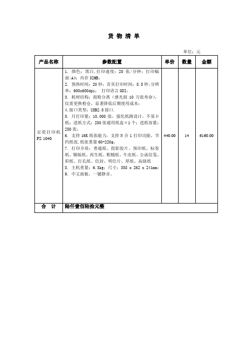
9.中文面板,一键静音。
440.00
14
6160.00
合计
陆仟壹佰陆拾元整
货物清单
单位:元
产品名称
参数配置
单价
数量Βιβλιοθήκη 金额京瓷打印机FS-1040
1.颜色:黑白,打印速度:20张/分钟;打印幅面:A4;内存32MB;
2. 预热时间:20秒;首页打印时间:8.5秒;分辨率:600x600dpi; 打印语言GDI;
3.耗材结构:鼓粉分离(感光鼓10万张寿命),仅需更换粉仓,显著降低后期使用成本;
4.接口类型:USB2.0接口.
5.月打印量:10,000张,强化纸路设计,不易卡纸;进纸方式:250张通用纸盒×1个;进纸容量:250张,
6.支持16K纸张能力,支持N合1打印功能,节约纸张,纸张重量60-220g;
7. 打印介质:普通纸、投影胶片、预印纸、标签纸、铜版纸、再生纸、粗糙纸、牛皮纸、公函信笺、彩纸、打孔纸、信封、明信片、厚纸、高级纸
MPS150非隔离电源应用规格书MP150方案

Breakdown voltage
V(BR)DSS
500
Supply Voltage Management (VCC Pin)
VCC level (increasing) where the internal regulator stops
VCCOFF
5.4
VCC level (decreasing) where the internal regulator turns on
Notes: 1) Exceeding these ratings may damage the device. 2) The maximum allowable power dissipation is a function of the
maximum junction temperature TJ(MAX), the junction-toambient thermal resistance θJA, and the ambient temperature TA. The maximum allowance continuous power dissipation at any ambient temperature is calculated by PD(MAX)=(TJ(MAX)-TA)/θJA. Exceeding the maximum allowance power dissipation will cause excessive die temperature, and the regulator will go into thermal shutdown. Internal thermal shutdown circuit protects the device from permanent damage. 3) The device is not guaranteed to function outside of its operating conditions. 4) Measured on JESD51-7, 4-layer PCB.
FM147A 八路热电偶模拟量输入模块使用说
硬件产品手册北京和利时系统工程股份有限公司 4/12/2006FM147A8路热电偶模拟量输入模块目录1FM147A模块的基本说明 (1)1.1 简介 (1)1.2 组成 (1)1.3 特点和功能 (2)2原理说明 (2)3使用说明 (4)3.1状态指示灯说明 (4)3.2底座端子接线说明 (5)3.2.1 底座接线端子的定义 (5)3.2.2热电偶信号或毫伏电压信号接线说明 (6)4技术指标 (7)5温度补偿方法 (8)6附录 (10)热电偶温度测量范围 (10)HollySys块式I/OHollySys 1表1-1 FM147A 的采样信号范围 序号 信号范围 1 -5~+75mV 2 -5~+35mV 3 0~+78.125mV 4 0~+39.0625mV FM147A八路热电偶模拟量输入模块1 FM147A 模块的基本说明1.1 简介FM147A 型模块是智能型8路热电偶模拟量输入模块,是HollySys 公司采用目前世界上先进的现场总线技术(ProfiBus-DP 总线)而新开发的工业现场级热电偶模拟量输入模块。
通过与配套的底座FM131A 连接,用于处理从现场来的热电偶毫伏电压1和一般毫伏电压输入信号。
FM147A 作为ProfiBus-DP 的从站通过ProfiBus-DP 总线把采集到的信号及相关诊断信息上传到ProfiBus-DP 的主站。
它是智能型的现场总线产品,是构成HollySys 公司的MACS TM 系统的通用I/O单元的一种。
FM147A 与J 、K 、N 、E 、S 、B 、R 、T 型热偶一次测温元件相连,可处理工业现场的温度信号。
由于它的测量信号范围可达-5mV ,因此可以采样一定范围的负温。
通过组态软件正确组态,该模块可以对在-5mV ~+78.125mV 范围内的线性毫伏信号采样处理。
因此它使用范围广、功能全面。
1.2 组成FM147A 模块由8路双端输入型TC 模拟输入板、I/O 通用型智能处理板和外壳结构件组成。
美国MOTOROLA 压力传感器说明书

美国MOTOROLA压力传感器美国MOTOROLA公司的MPX系列硅压力传感器,主要以气压测量为主,适合用于医疗器械,气体压力控制等领域,输出数字信号。
其测量方式可分为:表压(GP)、绝压(A、AP)、差压(D、DP)型。
在宽温度范围工作时需外加补偿网络和信号调整电路。
具体型号分类而定名称:MPX2010DP 名称:MPX5700DP MPX5700GP 名称:MPX2100AP名称:MPX5500DP 名称:MPX5100AP 名称:MPX5050DP名称:MPX5010DP 名称:MPX4115AP 名称:MPX2200A 名称:MPX2200AP 名称:MPXH6115A6U 名称:MPX4250DP名称:MPX4115A 名称:MPX2202DP 名称:MPX2102AP名称:MPX2053GP 名称:MPXY8300A6U 压力传感器 名称:触力型压力传感器 FSG15N1A 名称:硅压力传感器 MPXH6115A 名称:MPX5700DP 硅压力传感器 名称:MPX53GP 硅压力传感器 名称:压力传感器FPM07 名称:轮胎压力传感器TP015 名称:轮胎压力传感器NPP301名称:Freescale 压力传感器 MPX2010DP商斯达实业传感器与智能控制分公司专门从事各种进口传感器的营销工作,代理多家欧美知名公司的产品。
涉及压力、温度、湿度、电流、液位、磁阻、霍尔、流量、称重、光纤、倾角、扭矩、气体、光电、位移、触力、红外、速度、加速度等多种产品。
广泛应用于航空航天、医疗器械(如血压计)、工业控制、冶金化工、汽车制造、教育科研等领域。
商斯达实业代理的品牌产品主要有:压 力:Kulite、ACSI、Honeywell、Entran、Gems、Dwyer、SSI、Smi、Senstronics、Intersema、Motorola、 NAIS、E+H、Fujikura、Dytran、APM称重测力:Transcell、HBM、Interface、Thamesside、Philips、Entran 温 湿 度:Honeywell、Dwyer流 量:Gems、Dwyer、Honeywell、Folwline、WorldMagnetics 液 位:Honeywell、Siccom、Gems、Dwyer、Kulite、SSI 加 速 度:Entran、Silicondesigns、Dytran 压力开关:ACSI、Gems、Dwyer、台湾矽微航空器材:TexTech 隔音材料、Honeywell 薄膜加热片、DigirayX 射线探伤仪 仪 表:Honeywell、Transcell、东辉、上润、AD、东崎商斯达实业 除代理上述产品外,还有几条传感器生产线,一条压力传感器组装线,可为用户提供各种用途的、特殊要求的配套产品。
CDEP147NP-1R1M中文资料

2. 1 ± 0 .2
②
1/3
元器件交易网
POWER INDUCTORS <SMD Type: CDEP Series>
Type: CDEP147
◆ Specification
1-Low D.C.R Type
Part Name ※ CDEP147NP-ØR5M□-125 CDEP147NP-1R1M□-125 CDEP147NP-2RØM□-125 CDEP147NP-3R1M□-125 CDEP147NP-4R5M□-125 CDEP147NP-6R1M□-125 CDEP147NP-8RØM□-125 CDEP147NP-1ØØM□-125 CDEP147NP-12ØM□-125 Stamp 0R5ML 1R1ML 2R0ML 3R1ML 4R5ML 6R1ML 8R0ML 100ML 120ML Inductance [Within] 100kHz/1V 0.5μH±20% 1.1μH±20% 2.0μH±20% 3.1μH±20% 4.5μH±20% 6.1μH±20% 8.0μH±20% 10.0μH±20% 12.0μH±20% D.C.R. (mΩ) Max.(Typ.) (at 20℃) 1.18(0.98) 1.46(1.22) 2.02(1.69) 3.23(2.70) 4.97(4.14) 6.03(5.02) 7.80(6.50) 9.85(8.21) 13.31(11.1) Saturation Current (A)※1 (at 20℃) 39.6(49.5) 26.4(33.0) 19.6(24.5) 16.0(20.0) 13.6(17.0) 11.6(14.5) 10.0(12.5) 9.2(11.5) 8.0(10.0) (at100℃) 33.9(42.4) 22.8(28.5) 16.8(21.0) 13.6(17.0) 11.6(14.5) 10.0(12.5) 8.2(10.3) 7.6(9.5) 6.6(8.2) Temperature Rise current (A) ※2 23.0 21.5 20.0 17.5 16.0 12.5 11.0 10.0 8.5
碳带条码打印机标准

碳带条码打印机标准碳带条码打印机是一种用于打印条形码标签的设备,常用于物流、零售、制造等领域。
针对碳带条码打印机,相关的标准通常包括设备的性能、安全、通用规范以及打印质量等方面的规定。
以下是一般情况下碳带条码打印机标准的相关内容:1. ISO/IEC 15416 -条形码符号品质测试这一国际标准规定了对于打印在条形码标签上的条形码符号的质量进行测试的方法。
其中包括对条码的打印质量、光学反射和读取可靠性的要求。
2. ISO/IEC 19752 -激光打印机和多功能设备打印输出质量的测量方法虽然这个标准主要适用于激光打印机,但对于评估碳带条码打印机的打印输出质量也提供了一些通用的测量方法和指南。
3. IEC 62368-1 -声明一体化电路(ICT)设备的安全性第1部分:一般要求这一国际电工委员会标准适用于信息和通信技术(ICT)设备的安全性,其中可能包括碳带条码打印机。
该标准规定了设备的一般安全性要求,确保设备在正常使用情况下对用户和环境都是安全的。
4. ISO 9001 -质量管理体系对于制造商而言,ISO 9001是一个通用的质量管理体系标准,可以帮助确保生产的设备符合一定的质量标准。
生产碳带条码打印机的制造商通常会寻求获得这一质量管理体系的认证。
5. IEC 60950 -信息技术设备安全第1部分:一般要求这个标准规定了信息技术设备的安全性要求,包括碳带条码打印机在内。
它关注设备在正常使用和异常条件下的安全性。
6. 标签材料相关标准除了打印机自身的标准外,与条形码打印相关的标签材料也有一系列相关的标准,这些标准包括材料的耐久性、粘性、防水性等方面的测试和规定。
7. 产品认证标志碳带条码打印机通常需要符合特定的认证标志,这可能是由国家或地区的标准化机构颁发的,例如CE标志(欧洲符合性)。
8. 碳带使用规范一些标准可能也包括关于碳带的使用和更换的规范,以确保在打印过程中的耗材使用符合特定的要求。
MPS 电源全面解决方案

The Future of Analog IC Technology
®
开关电源 ---单相表反激拓扑
反激方案 (隔离方案, 副边或原边控制)
• “+”:
– 节能,高效。 – 更小,更轻便。 – 副边控制具有更高的输出精度。
• “-”:
– 三相方案需要特别处理。 – 原, 副边控制在成本和精度上的选择。
HR1000
Opto
AC IHale Waihona Puke putEMI Fitler
HF81
+
Output
+
PFC Controller
Flyback SR Controller
MP44010
Flyback Controller
HFC0100
AC Input
EMI Fitler +
MP6902 MP6910 MP6912
Opto
MPS 关键竞争力 专利保护的专有工艺技术 Fabless 运作, 但是…. MPS专有的工艺技术
BiCMOS / DMOS (BCD) 100% of Products Run on our Process ½ the Mask Layers vs. Competition MPS Engineers work inside Partner Foundries Very Few Fabless Companies have a Proprietary Process
®
MPS 及其全球领先的电源模拟IC技术 智能表电源设计分析
MPS 智能表电源全面解决方案
MPS/中电华星智能表电源参考设计举例浏览 Q&A
The Future of Analog IC Technology
cd40147中文资料pdf
海纳电子资讯网www.fpga-arm.com为您提供各种IC的应用资料
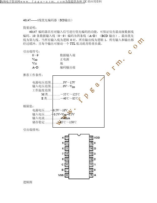
40147------4线优先编码器(BCD输出)
简要说明:
40147 编码器具有对输入信号进行优先编码的功能,可保证仅有最高级数据线
编码。10 条数据输入线(0~9)编码为四条线(A~D)(BCD 输出)。最高优先 线为第九线。当所有输入线为逻辑 0 时,所有输出线为逻辑 1,所有输入和输出都 经过缓冲,且每个输出可驱动一个 TTL 低功耗肖特基负载。
5.0
10.0
15.0
- -
100
c 80
200
ns
. 100
m 80
r7.5
pF
a
-
a
g
p
f
.
w
w
w
参数
VOL 输出低 电平电压 (最大)
VOH 输出高 电平电压 (最小)
VO (V)
-
-
VIL 输入低 电平电压
(最大)
0.5/4.5 1.0/9.0 1.5/13.5
VIH 输入高 电平电压
(最小)
4.5/0.5 9.0/1.0 13.5/1.5
IOH 输出高电 平电流
2.5 4.6
(最小)
9.5 13.5
10/0 10.0
1.0 2.0
GM814X数据手册

GM8141/2 兼容SPI TM 总线的UART 扩展芯片 数据手册 2006.6 成都国腾微电子有限公司GM8141/2 版本记录:1.1 当前版本时间:2006年6月 新旧版本改动比较: 旧版 文档页数 当前版本 文档页数 主题(和旧版本相比的主要变化) 22 24 8141-SO封装改为SOP20 如果您有技术、交付或价格方面的任何问题,请联系成都国腾微电子有限公司的相关办公室或当地的代理商,或访问我们的网站:www.gticc.com ,谢谢! 编制时间:2006年6月 由成都国腾微电子有限公司发布 发布地点:成都 成都国腾微电子有限公司版权所有。
数据手册 第 1 页 共 23 页 2006年6月目录1 概述 (3)2 特征 (3)3 封装及引脚功能说明 (3)4 功能描述 (5)4.1 SPI接口 (5)4.2 工作模式 (5)4.2.1 基本操作 (5)4.2.2 功能寄存器 (6)4.3UART接口 (10)4.4中断 (10)4.5 ShutDown模式 (11)4.5.1 软件shutdown条件及步骤 (12)4.5.2 软件shutdown的唤醒条件及步骤 (12)4.5.3 硬件shutdown条件及步骤 (12)4.5.4 硬件shutdown的唤醒条件及步骤 (12)4.5.5 软件shutdown与硬件shutdown之间的关系 (12)4.5.6 软件/硬件shutdown 时序图 (12)4.6IrDA模式 (13)4.7 CS片选信号与总线使能控制 (13)4.8 外部复位功能 (14)4.9晶振 (14)4.10 其他应用示意图 (15)5 产品选型指南 (18)6 参数指标 (18)6.1 极限工作条件 (18)6.2 推荐工作条件 (19)6.3 电学参数 (19)6.4 SPI接口参数 (20)7 机械尺寸 (20)7.1 DIP16封装尺寸图 (20)7.2 DIP20封装尺寸图 (21)7.3 SOP20封装尺寸图 (22)数据手册 第 2 页 共 23 页 2006年6月1概述该芯片可以将一个标准SPI接口扩展成2个(GM8141)或4个(GM8142)标准的UART,并具备两种工作模式:串口扩展模式和广播模式。
MPS-140801用户手册

Morpheus electronic
MPS-140801
▪ 52.734K ▪ 26.367K ▪ 13.183K ▪ 6.592K ▪ 3.286K ▪ 1.643K 2.6、分辨率 ▪ 52.734K 采样率下,噪声峰峰值 < 400 微伏,无噪声分辨率 15.7bit,有效分辨率
18.6bit,信噪比 103dB; ▪ 26.367K 分辨率下,噪声峰峰值 < 250 微伏,无噪声分辨率 16.2bit;噪声有效值 <
设 色 ( ) 状 指 灯 亮则 正 正 ▪ 备的率 LED DAQ 为采集与传输的 态 示 。LED 灭 则 停 或 断 , 采集 止 数据传输中 。
系统 在 常采集;LED
三 1. 、首次驱 使用动本安卡装时,计算机将提示“发现新硬件”,如下图所示。选择“从列表或指定位 置安装(高级)”,并点击“下一步”。
Morpheus electronic
MPS-140801
MPS-140801 8 通道 24 位 USB 信号采集卡
使用说明
Ver 1.0
Morpheus electronic
第一章 产品概述
MPS-140801
MPS-140801 8 通道 24 位 USB 信号采集卡
一、 产品简介
MPS-140801 是一款基于 USB 总线的高性能信号采集卡。MPS-140801 具有八路大量程、 高采样率、低噪声的高性能同步信号采集通道。每个通道的量程为±10V,采样率高达 52.734Ksps,并能保证实时传输到计算机进行显示与分析。通过高性能 ADC 和先进的 DSP 信号处理技术,MPS-140801 同时还具有极低的采样噪声,在 1.643Ksps 采样率下采样噪声 峰峰值仅为 0.00004V,满量程信号的信噪比高达 50 万。多通道、高采样率和低噪声和同步 采样使 MPS-140801 能够满足科研与生产中绝大部分信号采集工程的需要。
宽范围电源设备A 1479用户手册版本1.1.1说明书

Wide range power supplyA 1479Instruction manualVersion 1.1.1, Code No. 20 752 653Distributor:Manufacturer:METREL d.d.Ljubljanska cesta 771354 HorjulSloveniaweb site: http://www.metrel.sie-mail: ****************Mark on your equipment certifies that this equipment meets the requirements of the EU (European Union) concerning safety and interference causing equipment regulations© 2016 METRELNo part of this publication may be reproduced or utilized in any form or by any means without permission in writing from METREL.A 1479 Wide range power supply Table of contents 1Introduction (4)1.1Main Features (4)1.2Safety considerations (4)1.3Applicable standards (4)2Connection and operation (6)2.1General guidelines and usage (6)2.2Connection between Line to Neutral conductors (7)2.3Connection between Line to Line conductors (7)2.4Standard socket connection (8)2.5Busbar connection (8)2.6Terminals and status indicator (9)2.7Strap installation (9)2.8Accessories (10)2.8.1Standard accessories (10)2.8.2Optional accessories (10)3Technical specifications (11)3.1General specifications (11)4Maintenance (12)4.1Cleaning (12)4.2Service (12)4.3Troubleshooting (12)4.4Manufacturer address: (13)1 IntroductionA 1479 Wide range power supply provides power supply for Metrel instruments directly from the distribution transformer or other nonconventional power source. It provides stabile power source (12 Vdc, 1 A) and safe installation to the user (CAT IV / 600V, IP 54).1.1 Main Features∙Wi de input supply range 85 V … 690 V (at 45 Hz … 65 Hz)∙Wide temperature range: -20 °C … +60 °C∙Overvoltage category: CAT IV / 600V (altitude up to 3000 m)∙Operating status indicator1.2 Safety considerationsTo ensure operator safety while using the A 1479 Wide range power supply and to minimize the risk of damage to the supply, please note the following general warnings:The power supply has been designed to ensure maximum operator safety. Usage in a way other than specified in this manual may increase the risk of harm to the operator!Do not use the power supply and/or accessories if any visible damage is noticed!The power supply contains no user serviceable parts. Only an authorized dealer can carry out service or adjustment!All normal safety precautions have to be taken in order to avoid risk of electric shock when working on electrical installations!Only use approved accessories which are available from your distributor!Maximum nominal voltage (L-N or L-L) on input terminals is 690 V RMS.1.3 Applicable standardsWide range power supply A 1479 is designed and tested in accordance with the following standards:Electromagnetic compatibility(EMC)EN 61326-2-2: 2013 Electrical equipment for measurement, controland laboratory use – EMC requirements –Part 2-2: Particular requirements - Testconfigurations, operational conditions andperformance criteria for portable test, measuringand monitoring equipment used in low-voltagedistribution systems∙Emission: Class A equipment (forindustrial purposes)Immunity for equipment intended for usein industrial locationsSafety (LVD)EN 61010-1: 2010 Safety requirements for electrical equipment formeasurement, control and laboratory use –Part 1: General requirementsEN 61010-031: 2002 + A1: 2008 Safety requirements for electrical equipment formeasurement, control and laboratory use –Part 031: Safety requirements for hand-heldprobe assemblies for electrical measurement andtestNote about EN and IEC standards:Text of this manual contains references to European standards. All standards of EN 6XXXX (e.g. EN 61010) series are equivalent to IEC standards with the same number (e.g. IEC 61010) and differ only in amended parts required by European harmonization procedure.2 Connection and operation2.1 General guidelines and usageA 1479 Wide range power supply provide power supply to various instruments from non-standard power sources. Moreover it is designed to connect directly to the measurand or measurement input terminals of instrument as shown on figure below. Backside of power supply is equipped with magnet for attaching device to the metallic enclosure.Figure 2.1: Wide range power supply usage and basic connection2.2 Connection between Line to Neutral conductorsTypically, Wide range power supply is connected between line and neutral wire, as shown on Figure 2.2.Figure 2.2: L-N Connection2.3 Connection between Line to Line conductorsAlternatively, Wide range power supply can be connected between line wires, as shown on Figure 2.3. Line to line voltage must be lower than maximal nominal input voltage of power supply.Figure 2.3: L-L Connection2.4 Standard socket connectionPower supply standard set include Plug adapter for connection to the standard socket, as shown on Figure 2.4.Figure 2.4: Socket Connection2.5 Busbar connectionPower supply standard set include crocodiles clips for connection directly to the busbars, as shown on Figure 2.5.Figure 2.5: Busbar Connection2.6 Terminals and status indicatorWarnings!Use original Input connection leads orplug adapter only!Max. permissible voltage on inputterminals is 690 V RMS !Figure 2.6: Terminals and indicatorsLegend:2.7 Strap installationCarrying strap is provided as standard accessory. In order to use, strap should be attached to the housing as shown on Figure 2.7.12e3eFigure 2.7: Strap installationInstallation procedure:2.8 Accessories2.8.1 Standard accessoriesTable 2.1: Wide range power supply standard accessories2.8.2 Optional accessoriesSee the attached sheet for a list of optional accessories that are available on request from your distributor.A 1479 Wide range power supply Technical specifications3 Technical specifications3.1 General specifications4 Maintenance4.1 CleaningTo clean the surface of the power supply use a soft cloth slightly moistened with soapy water or alcohol. Then leave the power supply to dry totally before use.Warnings:∙Do not clean the power supply while in use!∙Do not use liquids based on petrol or hydrocarbons!∙Do not spill cleaning liquid over the power supply!4.2 ServiceFor repairs under or out of warranty please contact your distributor for further information.4.3 Troubleshooting4.4 Manufacturer address:METREL d.d.Ljubljanska 77,SI-1354 Horjul,SloveniaTel: +(386) 1 75 58 200Fax: +(386) 1 75 49 095Email:****************http://www.metrel.si。
MP1471AGJ_r0.8

IA LDMP1471AHigh-Efficiency, 3A 16V, 500kHz Synchronous,Step-Down Converter In a 6-Pin TSOT 23PRELIMINARY SPECIFICATIONS SUBJECT TO CHANGEMPS CONFIDENTIAL AND PROPRIETARY INFORMATION – RTI USE ONLYThe Future of Analog IC TechnologyDESCRIPTIONThe MP1471A is a high-frequency, synchronous, rectified, step-down, switch-mode converter with internal power MOSFETs. It offers a very compact solution to achieve a 3A output current over a wide input supply range, with excellent load and line regulation. The MP1471A has synchronous-mode operation for FEATURES• Wide 4.5V-to-16V Operating Input Range • 110m Ω/57m Ω Low-R DS(ON) Internal PowerMOSFETs • Proprietary Switching-Loss–ReductionTechnology• High-Efficiency Synchronous-Mode0.010.1110M P SL D ONORDERING INFORMATIONPart Number*Package Top MarkingMP1471AGJ TSOT23-6 AGM * For Tape & Reel, add suffix –Z (e.g. MP1471AGJ–Z);PACKAGE REFERENCEV INV SWV BSSupply Voltage V IN...........................4.5V to 16VOutput Voltage V OUT................0.8V to V IN*DmaxOperating Junction Temp. (T J).-40°C to +125°C4) Measured on JESD51-7, 4-layer PCB.ELECTRICAL CHARACTERISTICS (5) V IN = 12V, T A = 25°C, unless otherwise noted.ND OLN ETYPICAL CHARACTERISTICSV IN = 12V, V OUT = 3.3V, L = 4.7µH, T A = +25°C, unless otherwise noted.010*********1.522.531.451.471.491.511.531.55MNT IA LD ON OTD IS TR IB U TYPICAL PERFORMANCE CHARACTERISTICSPerformance waveforms are tested on the evaluation board of the Design Example section. V IN = 12V, V OUT = 3.3V, L = 4.7µH, T A = +25°C, unless otherwise noted.V OUT2V/div.V IN10V/div.V SW5V/div.I INDUCTOR500mA/div.V OUT2V/div.V IN10V/div.V SW5V/div.I INDUCTOR2A/div.OUT2V/div.EN10V/div.SW10V/div.INDUCTOR1A/div.V OUT2V/div.V EN10V/div.V SW10V/div.I INDUCTOR2A/div.V OUT2V/div.V EN10V/div.V SW10V/div.V SW10V/div.I INDUCTOR2A/div.I INDUCTOR2A/div.SW5V/div.INDUCTOR2A/div.V OUT/AC20mV/div.V IN/AC500mV/div.IA LDON B UTETYPICAL PERFORMANCE CHARACTERISTICS (continued)Performance waveforms are tested on the evaluation board of the Design Example section. V IN = 12V, V OUT = 3.3V, L = 4.7µH, T A = +25°C, unless otherwise noted.V OUT 100mV/div.I OUT 1A/div.10V/div.SW 10V/div.INDUCTOR5A/div.PIN FUNCTIONSND ON EBLOCK DIAGRAMBST INENFBSWGNDD OM P SL D ONOPERATIONThe MP1471A is a high-frequency, synchronous, rectified, step-down, switch-mode converter with internal power MOSFETs. It offers a very compact solution to achieve a 3A output current over a wide input supply range, with excellent load and line regulation.The MP1471A operates in a fixed-frequency,forced to turn off.Internal Regulatorregulation. When V INoutput decreases.Error Amplifiersimplifies the control-loop design.AAM OperationThe MP1471A has AAM (Advanced Asynchronous Modulation) power-save mode for light load. The AAM voltage is set at 0.5V internally. Under the heavy load condition, theV COMP is higher than V AAM. When the clock goes high, the high-side power MOSFET turns on and remains on until V ILsense reaches the value set by the COMP voltage. The internal clock resets every time when V COMP exceed V AAM. In light-load condition, the value of V COMP is low. When V COMP is less than V AAM and V FB is less than V REF, V COMP ramps up until it exceeds V AAM. During this time, the internal clock is blocked, thus the MP1471A skips some pulses for PFM (Pulse Frequency Modulation) mode and achieves the light load power save.ClockFBValueEnableEN is a digital control pin that turns the regulator on and off: Drive EN HIGH to turn on the regulator, drive it LOW to turn it off. An internal 1MΩ resistor from EN to GND allows EN to float to shut down the chip.The EN pin is clamped internally using a 6.5V series-Zener-diode as shown in Figure 4. Connecting the EN input pin through a pullupLD O NEresistor to the V IN voltage limits the EN input current to less than 100μA.For example, with 12V connected to Vin, R PULLUP≥ (12V-6.5V)÷100μA =55kΩConnecting the EN pin directly to a voltage source without any pullup resistor requires limiting the amplitude of the voltage source to ≤6V to prevent damage to the Zener diode.ENGNDOver-Current-Protection and HiccupThe MP1471A has a cycle-by-cycle over-current limit for when the inductor current peak value exceeds the set current-limit threshold. First, when the output voltage drops until FB falls below the Under-Voltage (UV) threshold (typically 140mV) to trigger a UV event, the MP1471A enters hiccup mode to periodically restart the part. This protection mode is especially useful when the output is dead-shorted to ground. This greatly reduces the average short-circuit current to alleviate thermal issues and to protect the regulator. The MP1471A exits hiccup mode once the over-current condition is removed.Thermal ShutdownThermal shutdown prevents the chip from operating at exceedingly high temperatures. When the silicon die temperature exceeds 150°C, it shuts down the whole chip. When the temperature falls below its lower threshold voltage and currents, and then the internal regulator is enabled. The regulator provides astable supply for the remaining circuits.Three events can shut down the chip: EN low, V IN low, and thermal shutdown. The shutdown procedure starts by initially blocking the signaling path to avoid any fault triggering. The COMP voltage and the internal supply rail are then pulled down. The floating driver is not subject to this shutdown command.IA LDON TEAPPLICATION INFORMATIONSetting the Output VoltageThe external resistor divider sets the output voltage. The feedback resistor R1 also sets the feedback-loop bandwidth through the internal compensation capacitor (see the Typical Application circuit). Choose R1 around 10k Ω, and R2 by:OUT R1R2V =maximum load current for most applications. For highest efficiency, select an inductor with a DC resistance less than 15m Ω. For most designs, derive the inductance value from the following equation.OUTIN OUT 1IN L OSCV (V V )L V I f ×−=×Δ× Where ΔI L is the inductor ripple current. Choose an inductor current approximately 30% of the maximum load current. The maximum inductor peak current is:2I I I LLOAD )MAX (L Δ+= Under light-load conditions (below 100mA), use a larger inductance for improved efficiency. Selecting the Input CapacitorThe input current to the step-down converter is discontinuous, and therefore requires a capacitor to both supply the AC current to the step-down converter and maintain the DC input voltage. Use low ESR capacitors for the best performance, such as ceramic capacitors with = 2V OUT ,sufficient charge to prevent excessive input voltage ripple. Estimate the input voltage ripple caused by the capacitance with:LOAD OUT OUT IN IN S IN I V VV 1f C1V V ⎛⎞Δ=××−⎜⎟×⎝⎠Selecting the Output CapacitorThe output capacitor (C2) maintains the DC output voltage. Use ceramic, tantalum, or low-ESR electrolytic capacitors. Use low ESR capacitors to limit the output voltage ripple. Estimate the output voltage ripple with:IA LEOUT OUT OUT ESR S 1IN S V V 1V 1R f L V 8f C2⎛⎞⎛⎞Δ=×−×+⎜⎟⎜⎟×××⎝⎠⎝⎠ Where L 1 is the inductor value and R ESR is theequivalent series resistance (ESR) of the outputcapacitor.For ceramic capacitors, the capacitancedominates the impedance at the switchingfrequency and causes most of the outputvoltage ripple. For simplification, estimate theoutput voltage ripple with:For most applications, use an IN4148 for the external BST diode is IN4148, and a 1µF capacitor for the BST capacitor.PC Board LayoutPCB layout is very important to achieve stable operation. For best results, use the followingguidelines and Figure 8 as reference. 1) Keep the connection between the input ground and GND pin as short and wide as possible.2) Keep the connection between the input capacitor and IN pin as short and wide as possible. 3) Use short and direct feedback connections. Figure 8: Sample LayoutM P SI ALD ONU TEDesign ExampleBelow is a design example following the application guidelines for the specifications:Table 2—Design ExampleV IN 12VV OUT 3.3VIo 3A The detailed application schematic is shown in Figure 9. The typical performance and circuit waveforms have been shown in the TypicalDTYPICAL APPLICATION CIRCUITSFigure 81: 12V IN , 2.5V/3AN D ODO U T E NOTICE: The information in this document is subject to change without notice. Users should warrant and guarantee that third party Intellectual Property rights are not infringed upon when integrating MPS products into any application. MPS will not assume any legal responsibility for any said applications.PACKAGE INFORMATIONTSOT23-6。
Application Note AC147说明书
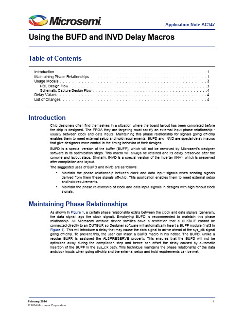
Application Note AC147February 20141© 2014 Microsemi CorporationUsing the BUFD and INVD Delay MacrosTable of ContentsIntroductionChip designers often find themselves in a situation where the board layout has been completed before the chip is designed. The FPGA they are targeting must satisfy an external input phase relationship -usually between clock and data inputs. Maintaining this phase relationship for signals going off-chip enables them to meet external setup and hold requirements. BUFD and INVD are special delay macros that give designers more control in the timing behavior of their designs.BUFD is a special version of the buffer (BUFF), which will not be removed by Microsemi’s designer software in its optimization steps. This macro will always be retained and its delay preserved after the compile and layout steps. Similarly, INVD is a special version of the inverter (INV), which is preserved after compilation and layout.The suggested uses of BUFD and INVD are as follows:•Maintain the phase relationship between clock and data input signals when sending signals derived from them these signals off-chip. This application enables them to meet external setup and hold requirements.•Maintain the phase relationship of clock and data input signals in designs with high-fanout clock signals.Maintaining Phase RelationshipsAs shown in Figure 1, a certain phase relationship exists between the clock and data signals (generally,the data signal lags the clock signal). Employing BUFD is recommended to maintain this phase relationship. All Microsemi antifuse device families have a restriction that a CLKBUF cannot be connected directly to an OUTBUF, so Designer software will automatically insert a BUFF module (inst3 in Figure 1). This will introduce a delay that may cause the data signal to arrive ahead of the sys_clk signal going off-chip. To prevent this, the user can insert a BUFD macro in his netlist. The BUFD, unlike a regular BUFF, is assigned the ALSPRESERVE property. This ensures that the BUFD will not be optimized away during the compilation step and hence can offset the delay caused by automatic insertion of the BUFF in the sys_clk path. This technique maintains the phase relationship of the data andclock inputs when going off-chip and the external setup and hold requirements can be met.Introduction . . . . . . . . . . . . . . . . . . . . . . . . . . . . . . . . . . . . . . . . . . . . . . . . 1Maintaining Phase Relationships . . . . . . . . . . . . . . . . . . . . . . . . . . . . . . . . . . . . . 1Usage Models . . . . . . . . . . . . . . . . . . . . . . . . . . . . . . . . . . . . . . . . . . . . . . . 3HDL Design Flow . . . . . . . . . . . . . . . . . . . . . . . . . . . . . . . . . . . . . . . . . . . . . .3Schematic Capture Design Flow . . . . . . . . . . . . . . . . . . . . . . . . . . . . . . . . . . . . . . .4Delay Values . . . . . . . . . . . . . . . . . . . . . . . . . . . . . . . . . . . . . . . . . . . . . . . 4List of Changes . . . . . . . . . . . . . . . . . . . . . . . . . . . . . . . . . . . . . . . . . . . . . . 4Using the BUFD and INVD Delay Macros2In Figure2, the clock signal coming from the CLKBUF has a high fanout. This means increased capacitive loading and hence increased delay. In contrast, the data signal has a fanout of only one. The clock network’s high fanout may allow the data input to (undesirably) lead the clock signal. Again, introducing one or more BUFD macros (inst1) in the data signal path provides enough delay to offset the delay of the high-fanout clock net.Figure 1 • Control of Phase Relationship between Data and System Clock using BUFDUsage Models3If inversion of the signal is required in addition to delay, the INVD macro is available. Again, the ALSPRESERVE property is assigned to this macro to avoid elimination during optimization steps.Usage ModelsHDL Design FlowNone of the synthesis tools that support Microsemi technologies will infer the INVD or BUFD macros in the synthesized netlist. Simulation library models of INVD and BUFD, similar to their INVD and BUFF counterparts, are available from Microsemi in both VHDL and Verilog. The manual process for buffer insertion is as follows:1.Import the synthesized netlist into Designer. Run compile and layout.2.Invoke Timer from Designer to check the timing/phase relationships for the signals of interest.ing a text editor, manually modify the netlist and insert BUFD and/or INVD macros into thedesired paths.4.Import the modified netlist into Designer. Again run compile and layout.5.Invoke Timer again to review the delays for the signals of step 2.If necessary, repeat steps 3 through 5 until the design timing requirements are met.Figure 2 • Control of Phase Relationship in Designs with High Clock FanoutsUsing the BUFD and INVD Delay Macros4Schematic Capture Design FlowINVDs and BUFDs are available for the following Microsemi-supported schematic capture tools:•ConceptHDL PE13.5 and PE13.6•Mentor Graphics c.4 and D.1•Workview Office 7.5•Powerview 6.1•ePD 1.0•ePD 1.1 TypicalTo avoid inadvertent instantiation of INVD or BUFD where INV or BUFF is intended, the graphicalsymbols for INVD and BUFD have warning labels "Special Use Only." The flow for buffer insertion is as follows:1.Generate an EDIF netlist with the schematic tool.2.Import the EDIF netlist into Designer. Run compile and layout.3.Invoke Timer from Designer to check the timing/phase relationships for the signals of interest.4.Edit the schematics to insert BUFD and/or INVD macros into the desired paths.5.Check and save your schematics. Generate an EDIF netlist from the modified schematics.6.Import the modified netlist into Designer. Again run compile and layout.7.Invoke Timer again to review the delays for the signals of step 3.8.If necessary, repeat steps 4 through 7 until the design timing requirements are met.Delay ValuesTable 1 shows the rising (R) and falling (F) delays for INVD and BUFD in different Microsemi families.These values are obtained using the fastest speed grade for the device using typical temperature,voltage, and process corners as well as optimized placement. Actual delay numbers may vary with the device, speed grade, and actual placement.List of ChangesThe following table lists critical changes that were made in the current version of the document.Table 1 • BUFD/INVD Delay for Various Microsemi Technology FamiliesACT1ACT2ACT33200DX 42Mx SX eX RTAX-S Units BUFD R 3.9 4.3 2.6 4.2 1.80.7 1.1 4.5ns F 3.7 3.5 2.5 3.4 1.60.7 1.1 4.6ns INVD R 3.8 4.3 2.4 3.9 1.80.7 1.1 6.5ns F3.6 3.6 2.2 3.2 1.60.7 1.1 6.1nsSpeed Grade-3-1-3-3-3-3STD-1Revision ChangesPage Revision 1(February 2014)Table 1 is updated to include RTAX-S values (SAR 47788).45192673-1/02.14© 2014 Microsemi Corporation. All rights reserved. Microsemi and the Microsemi logo are trademarks of Microsemi Corporation. All other trademarks and service marks are the property of their respective owners.Microsemi Corporation (NASDAQ: MSCC) offers a comprehensive portfolio of semiconductor solutions for: aerospace, defense and security; enterprise and communications; and industrial and alternative energy markets. Products include high-performance, high-reliability analog and RF devices, mixed signal and RF integrated circuits, customizable SoCs, FPGAs, and complete subsystems. Microsemi is headquartered in Aliso Viejo, Calif. Learn more at .Microsemi Corporate HeadquartersOne Enterprise, Aliso Viejo CA 92656 USA Within the USA: +1 (949) 380-6100Sales: +1 (949) 380-6136Fax: +1 (949) 215-4996。
MP芯片资料简介方案

MP芯片资料简介MP3芯片资料简介壹、飞利浦系列|技术交流|资料下载|图书杂志|家电资讯2m8Q o r-l《家电维修》技术论坛a ^ A7p*T k l产地:荷兰如果壹定要评出目前市场上最好的MP3解码芯片的话,那么无疑就是飞利浦芯片了。
飞利浦家族的解码芯片于业界壹直以其“功能全,音质好,价格高”而著称。
飞利浦的解码芯片壹般均采用的是BGA封装工艺,而国内的这方面技术相当有限,此外,由于飞利浦的解码芯片需要搭配另外的控制芯片电路协同工作,所以产品成本较高。
所以采用飞利浦解码芯片的厂商往往均定位于中高价位,如MPIO和IRIVER这俩家韩国的MP3专业厂商。
这俩个品牌壹个最主要的共同特点就是于产品中全面采用了飞利浦的解码芯片。
因此,他们的产品拥有很高的音质和品质,成为全球MP3爱好者追逐的对象。
#x;V3g#D(y!s&[ s N|技术交流|资料下载|图书杂志|家电资讯%q2e{ L#N8t1、飞利浦SAA775X系列(SAA7750/7751/7752/7753)飞利浦SAA775x芯片是目前市场上MP3播放器解码芯片组中功能最全(支持CD直录),效果最好的解码芯片之壹。
该解码芯片的音质表现为:低音下沉较深、中音表现出色、而相比之下高音则显得壹般。
;}3v1T U^%t z.{ cj+Q5~因为SAA775x中内含DSP(DigitalSignalProcessing,数字信号处理)和32位ARMRISC 处理器,所以能用超高集成度的单颗芯片,音频解码和语音编码等工作,且且能够加入SDMI(SecureDigitalMusicInitiative,安全式数字音乐)保护。
其中SAA7750内含DSP和32位ARMRISC处理器,信噪比为90dB。
该芯片兼容多段多档位EQ智能音效,支持以ADPCM格式保存语音记录、同步显示歌名和歌曲信息、Line-in直录,此外仍支持USB1。
1/2。
0标准,支持多重音乐格式解码。
川仪M系列电动执行机构样本

33
93.5
114
150
160
210
280
330
400
142
151.5
175
198
81
83
94
113
4-M16深25 4-M20深30
8-M16深22
8-M20深 32
—
4
4
4
—
130
200
230
140
165
254
298
204
244
310
350
35
35
54
54
75
80
105
105
104
130
133
158
葵花接线盒
插拔式接线方式让更换执行机构变得更加方便 快捷,只需把葵花盘插入接线盒即可,免去了 二次接线
绝对编码器
阀输出轴带动绝对编码器转动,形成的编码信 号送入主控芯片计算出当前阀位值,用作阀位 显示信号。由于绝对编码器获取的是阀位的绝 对信息,掉电和干扰均不会对其造成影响,得 到的阀位永远是正确的。
520
630
135
223
270
338
448
580
52.5
36
40
36
36
25
68.5
93.5
114
150
160
250
15
25
23
24
30
30
263.5
332
369.5
F14:46(618) F16:466
668
666
477
546
583
678(832)F16:738
MPS-G磁性气缸传感器说明书.pdf_1705404800.116922

带 2/3 开关点和 IO-Link(至多 8 个开关点)且具有诊断功能的 MPS-G磁性气缸传感器所说明的产品MPS-G制造商SICK AGErwin-Sick-Str.179183 Waldkirch, Germany德国法律信息本文档受版权保护。
其中涉及到的一切权利归西克公司所有。
只允许在版权法的范围内复制本文档的全部或部分内容。
未经西克公司的明确书面许可,不允许对文档进行修改、删减或翻译。
本文档所提及的商标为其各自所有者的资产。
© 西克公司版权所有。
原始文档本文档为西克股份公司的原始文档。
2操作指南 | 带 2/3 开关点和 IO-Link(至多 8 个开关点)且具有诊断功能的 MPS-G8028201.1JLZ/2023/05/05 | SICK如有更改,恕不另行通知内容内容1关于本文档的 (5)1.1更多信息 (5)1.2符号和文档约定 (5)2安全信息 (6)2.1规定用途 (6)2.2违规使用 (6)2.3责任范围 (6)2.4对专业人员和操作人员的要求 (6)2.5危险提示与作业安全 (7)2.6关于 UL 认证的提示 (7)3产品说明 (8)3.1产品识别 (8)3.1.1设备视图 (8)3.2产品特征 (8)3.2.1产品特点 (8)3.3作业方法 (10)3.3.1工作原理 (10)3.3.2探测范围 (10)3.3.3位置输出 (10)3.3.4在手动示教最多 3 个开关点之后的开关性能 (11)3.3.5动态示教 2 个开关点之后的开关性能 (12)3.3.6动态示教 3 个开关点之后的开关性能 (14)4运输和仓储 (19)4.1运输 (19)4.2运输检查 (19)4.3储存环境 (19)5装配 (20)5.1安装要求 (20)5.2可选的配件 (20)5.3固定/安装 (20)6电气安装 (21)6.1安全性 (21)6.1.1关于电气安装的提示 (21)6.1.2接线提示 (21)6.2接口 (22)6.2.1引脚分配/接口示意图 + 芯线颜色 (22)6.3连接工作电压 (23)7调试 (24)7.1调试步骤概览 (24)8028201.1JLZ/2023/05/05 | SICK操作指南 | 带 2/3 开关点和 IO-Link(至多 8 个开关点)且具有诊断功能的 MPS-G3如有更改,恕不另行通知内容7.2驱动装置的定位 (24)7.3初次将传感器投入运行 (24)8操作 (26)8.1有关操作的一般提示 (26)8.2操作及显示元件 (26)8.2.1操作元件 (26)8.2.2显示元件 (26)8.3示教模式 (27)8.3.1动态示教 (28)8.3.2手动示教 (30)8.4通过 IO-Link 操作 (34)8.4.1过程数据结构 (34)8.4.2常规功能 (35)8.4.3通过 IO-Link 的设置选项 (35)8.4.4激励元件诊断功能 (44)8.4.5流程诊断功能 (46)9故障排除 (52)10维护 (53)11停机 (54)11.1备用设备 (54)11.2拆卸和废弃处理 (54)11.3寄回设备 (54)12技术数据 (55)12.1尺寸图 (56)13术语表 (58)14附件 (60)14.1示教程序概览 (60)14.2合规性和证书 (60)4操作指南 | 带 2/3 开关点和 IO-Link(至多 8 个开关点)且具有诊断功能的 MPS-G8028201.1JLZ/2023/05/05 | SICK如有更改,恕不另行通知1关于本文档的1.1更多信息查看产品页面更多信息,请访问 SICK Product ID:/{P/N}。
- 1、下载文档前请自行甄别文档内容的完整性,平台不提供额外的编辑、内容补充、找答案等附加服务。
- 2、"仅部分预览"的文档,不可在线预览部分如存在完整性等问题,可反馈申请退款(可完整预览的文档不适用该条件!)。
- 3、如文档侵犯您的权益,请联系客服反馈,我们会尽快为您处理(人工客服工作时间:9:00-18:30)。
V
1.6
μA
0
μA
3.85
4.2
4.55
V
340
mV
1
ms
150
°C
20
°C
MP1471 Rev. 1.01
3
8/27/2013
MPS Proprietary Information. Patent Protected. Unauthorized Photocopy and Duplication Prohibited.
MOSFETs • Proprietary Switching-Loss–Reduction
Technology • High-Efficiency Synchronous-Mode
Operation • Fixed 500kHz Switching Frequency • Internal AAM Power-Save Mode for High
VIN ..................................................-0.3V to 17V VSW ......................................................................
-0.3V (-5V for <10ns) to 17V (19V for <10ns) VBS ......................................................... VSW+6V All Other Pins ...................................–0.3V to 6V Continuous Power Dissipation (TA = +25°C) (2)
MP1471 – SYNCHRONOUS, STEP-DOWN CONVERTER WITH INTERNAL MOSFETS
ELECTRICAL CHARACTERISTICS (5)
VIN = 12V, TA = 25°C, unless otherwise noted.
Parameter
Symbol Condition
The MP1471 requires a minimal number of
readily-available,
standard,
external
components and is available in a space-saving
6-pin TSOT23 package.
FEATURES
• Wide 4.7V-to-16V Operating Input Range • 150mΩ/70mΩ Low-RDS(ON) Internal Power
EN Input Current
VIN Under-Voltage Lockout Threshold, Rising VIN Under-Voltage Lockout Threshold Hysteresis Soft-Start Period Thermal Shutdown(5) Thermal Hysteresis(5)
MP1471 Rev. 1.01
2
8/27/2013
MPS Proprietary Information. Patent Protected. Unauthorized Photocopy and Duplication Prohibited.
© 2013 MPS. All Rights Reserved.
........................................................... 1.25W Junction Temperature ...............................150°C Lead Temperature ....................................260°C Storage Temperature................. -65°C to 150°C
IEN
INUVVth INUVHYS
τSS
VEN=2V VEN=0
Notes: 5) Guaranteed by design.
Min
Typ
Max Units
1
μA
0.83
mA
150
mΩ
70
mΩ
1
μA
3.5
4.2
A
400
490
580
kHz
88
92
%
90
ns
776
800
824
mV
1.4
1.5
1.6
V
1.23 1.32 1.41
© 2013 MPS. All Rights Reserved.
MP1471 – SYNCHRONOUS, STEP-DOWN CONVERTER WITH INTERNAL MOSFETS
ORDERING INFORMATION
Part Number* MP1471GJ
Package TSOT23-6
“MPS” and “The Future of Analog IC Technology” are registered trademarks of Monolithic Power Systems, Inc.
TYPICAL APPLICATION
VIN GND
EN
3 IN
BST 6 U1
SW 2 MP1471
IINVEN = 0V NhomakorabeaIq
VEN = 2V, VFB = 1V
HSRDS-ON VBST-SW=5V
LSRDS-ON Vcc=5V
SWLKG VEN = 0V, VSW =12V
ILIMIT
fSW
VFB=0.75V
DMAX VFB=700mV
τON_MIN
VFB
VEN_RISING
VEN_FALLING
The Future of Analog IC Technology
MP1471
High-Efficiency, 3A Peak, 16V, 500kHz Synchronous, Step-Down Converter In a 6-Pin TSOT 23
DESCRIPTION
The MP1471 is a high-frequency, synchronous, rectified, step-down, switch-mode converter with internal power MOSFETs. It offers a very compact solution to achieve a 3A peak output current over a wide input supply range, with excellent load and line regulation. The MP1471 has synchronous-mode operation for higher efficiency over the output current-load range.
Efficiency at Light Load • Internal Soft-Start • Over-Current Protection and Hiccup • Thermal Shutdown • Output Adjustable from 0.8V • Available in a 6-pin TSOT-23 package
Thermal Resistance (4) θJA θJC
TSOT-23-6............................. 100 ..... 55... °C/W
Notes: 1) Exceeding these ratings may damage the device. 2) The maximum allowable power dissipation is a function of the
5 EN
GND 1
FB 4
R3 40.2k
3.3V
R1 40.2k
R2 13k
VOUT
100
95
90
85
80
75
70
65
60
55
50
0.01
0.1
1
10
MP1471 Rev. 1.01
1
8/27/2013
MPS Proprietary Information. Patent Protected. Unauthorized Photocopy and Duplication Prohibited.
Supply Current (Shutdown) Supply Current (Quiescent) HS Switch-On Resistance LS Switch-On Resistance Switch Leakage Current Limit (5) Oscillator Frequency Maximum Duty Cycle Minimum On Time(5) Feedback Voltage EN Rising Threshold EN Falling Threshold
Recommended Operating Conditions (3)
Supply Voltage VIN ...........................4.7V to 16V Output Voltage VOUT......................0.8V to 0.9VIN Operating Junction Temp. (TJ). -40°C to +125°C