390、450测试设备简易说明
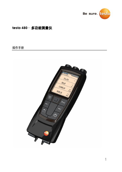
Testo 480 多功能测量仪 操作手册说明书
1testo 480 · 多功能测量仪操作手册2目录2 安全和环境 (5)2.1. 本文介绍 (5)2.2. 保证安全 (6)2.3. 保护环境 (7)3 规格 (8)3.1. 使用 (8)3.2. 技术数据 (8)4 产品说明 (11)4.1. 综述 (11)4.1.1. 便携式仪器 (11)4.1.2. 仪器接口 (12)4.1.3. 操控按键 (13)4.1.4. 显示屏 (14)5 入门知识 (16)5.1. 调试 (16)5.2. 产品 (19)5.2.1. 菜单 (19)5.2.2. 选择功能 (20)5.2.3. 退出菜单 (20)5.2.4. 切换到另外一个标签 (20)5.2.5. 输入数值 (20)5.2.6. 保存数值 (21)6 使用产品 (22)6.1. 设置操作 (22)6.2. 设置测量页面 (23)6.2.1. 计算的测量参数 (24)6.3. 收藏夹标签 (25)6.4. 探头菜单 (25)6.5. 数据管理浏览器菜单 (27)36.6. 测量和测量程序 (30)6.6.1. 保留(“保持”)测量数值 (30)6.6.2. 测量程序 (30)6.6.3. 栅格测量 (32)6.6.4. 紊流度测量 (36)6.6.5. 皮托管测量 (37)6.6.6. 使用风量罩测量 (38)6.6.7. 压力测量 (38)6.6.8. 二氧化碳测量 (39)6.6.9. 保存测量值 (40)6.6.10. 打印测量值 (41)6.6.11. 测量数值导出 (43)7 维护产品 (44)7.1.1. 电池护理 (44)7.1.2. 进行湿度调整 (44)7.1.3. 仪器固件更新 (45)8 提示和帮助 (51)8.1. 问题和解答 (51)8.2. 附件和备件 (52)42 安全和环境2.1. 本文介绍符号和书写标准警告一定要注意带有如下警告符号的信息,并采取规定的预防措施。
gs450光纤直放站综合测试仪使用说明
gs450光纤直放站综合测试仪使用说明GS450光纤直放站综合测试仪使用说明一、引言GS450光纤直放站综合测试仪是一种用于光纤通信系统中直放站的综合测试仪器。
本文将介绍GS450光纤直放站综合测试仪的使用方法和注意事项。
二、仪器介绍GS450光纤直放站综合测试仪是一种便携式测试仪器,可以用于测量光纤直放站的多项参数。
该测试仪具有高精度、高稳定性和易操作等特点,使得光纤直放站的调试和维护更加方便快捷。
三、使用方法1. 连接测试仪和光纤直放站:首先,将测试仪的光纤连接口与光纤直放站的输入端口相连;然后,将测试仪的电源线连接到电源插座,并打开电源开关。
2. 打开测试仪:按下测试仪上的电源按钮,待测试仪启动后,出现仪器的主界面。
3. 设置测试参数:在主界面上,选择需要测试的参数类型,如光功率、信号质量等。
根据具体需求,设置相应的测试参数。
4. 进行测试:点击开始测试按钮,测试仪将自动对光纤直放站进行测试,并显示测试结果。
5. 分析测试结果:根据测试仪显示的测试结果,对光纤直放站的性能进行分析。
如发现异常情况,可根据测试仪提供的帮助文档进行故障排查和修复。
四、注意事项1. 在操作测试仪之前,先阅读仪器的使用手册,了解仪器的功能和操作方法。
2. 使用测试仪时,应注意操作的准确性和稳定性,避免误操作导致测试结果不准确。
3. 在连接光纤时,应注意光纤的清洁和连接的牢固,避免因光纤连接不良导致测试结果出现异常。
4. 使用测试仪时,应注意安全问题,避免触电或其他意外伤害。
5. 在测试过程中,应注意测试仪的显示界面,及时发现异常情况并进行处理。
光纤直放站是光纤通信系统中重要的设备之一,其性能的稳定性对整个通信系统的正常运行起到至关重要的作用。
GS450光纤直放站综合测试仪的使用,可以帮助用户实时监测光纤直放站的性能,及时发现并解决潜在的故障问题,保障通信系统的可靠性和稳定性。
GS450光纤直放站综合测试仪是一种方便易用的测试仪器,通过正确使用该测试仪,可以有效提高光纤直放站的调试和维护效率,保障光纤通信系统的正常运行。
BARFIELD DPS450数字静压测试仪说明书

Barfield, Inc.4101 NW 29th Street, Miami, FL 33142 Tel: +1 305-894-5400 Fax: +1 Call us regarding export restrictionsDPS450 DimensionsDPS450 Digital Pitot Static Test SetThe new DPS450 completes an entire line of Barfield Digital Pitot-Static/Air Data testers. Designed to minimize aircraft downtime, the DPS450 is the newest and one of the lowest cost fully automated Air Data Testers meeting the high accuracy demands of Reduced Vertical Separation Minimum (RVSM) specifications on the market.All functions of the tester are fully automatic and require no manual sequencing of valves or regulators. The DPS450 has fully automatic control by means of the menu-driven high contrast electroluminescent display and tactile membrane keypad. The automated controller automatically generates and continuously maintains the input altitude, airspeed or V SI values. The DPS450 precisely maintains the input value (Ps,PT, Airspeed, Alt, etc.) overcoming any pressure values caused by a leaky system. A precision sensor on the static channel provides high accuracy altitude measurement and simulation. This high accuracy and stability (see Air Data Specifications for details) qualifies the DPS450 for certifying aircraft for RVSM operation and increases the calibration interval from 30 days to once every year. The sophisticated yet user friendly display is fully programmable for a range of test requirements. It can be configured, with limits and referred units of measurement, for individual aircraft types. The level of information displayed can be determined by the operator to suit the particular task at hand. In addition to the standard pitot-static functions of the DPS450, there are many additional advanced features that include: automatic go-to-ground, leak test mode and device under test protection amongst others. This enables the operator to undertake flightline testing accurately and efficiently, without compromising safety standards.Features Fully automated unit Optional handheld remote control Database capable of saving the limit data of different aircraft and stored in a battery backed memory GO TO GROUND feature automatically and safely depressurizes both systems to ambient pressure > Compact and lightweight for quick and easy portability.> Meets .0030 inHg accuracy on static channelIn.14.020.510.4Ibs.33cm.35.552.026.5kg 15TMCopyright © 2014 Barfield Inc. All Rights Reserved.。
K-09 RVSM

RVSM实行进程
我国已确定在2007年11月22日零时(北京时)在中国各空域内实施RVSM运行。
全球实施RVSM的区域及计划实施区域
加拿大北部 4/02
加拿大南部 1/05
欧洲1/02
日本韩国 9/29//05
高加索地区 3/17/05
美国本土 1/05
北大西洋 3/97 中东地区 11/03 太平洋 2/00 西太平洋 南中国海 2/02
RVSM基本适航要求
为进行RVSM运行,运营人需向当地的 适航管理部门提交申请,说明每一架航空 器的初始适航状态以及持续适航控制方式, 以获得每一架将在RVSM空域飞行的航空器 的适航批准,并且需完成规定的高度保持 确认和监控程序。
机载系统要求
• 两个独立的高度测量系统;(主高度表,大气数据计算机, 动静压管,静压口,AOA等以及防冰系统) • 一部具有高度报告能力的二次监视雷达应答机(SSR)。如 果只安装了一部,它必须具有转换到任意一个高度测量系统的 能力;(ATC应答机) • 一部高度警告系统;(主警告系统) • ACASII(自动防撞系统, ACASII 即TCAS7.0适用于RVSM环 境) • A320的初始构型已经满足上述机载系统要求
TASK 34-13-00-720-009 对大气数据系统的高度和空速数据进行功能测试
这项工作是利用了地面设备对大气数据管路系统进行测试,将试验数据与给出的 标准数值进行比较。
涉及RVSM运行的故障和工作
根据A320TSM,下列故障可能涉及RVSM运行
22-66-00-810-856
FAC or One FMGC
航空器系统的RVSM性能规范
高度警告系统:
当显示给飞行机组的高度偏离预定高度一个 标称值时,高度偏离警告系统应给出一个警告信 号。1997年1月1日以前完成型号合格审定申请的 航空器型号,这个标称值不应大于±90米(300 英尺)。 1997年1月1日以后完成型号合格审定 申请的航空器型号,这个标称值不应大于±60米 (200英尺)。
Fluke Ti480 Ti450多焦距测量仪说明书

Focus redefined.•Capture a clear, accurate image focused throughout the field of view with MultiSharp™ Focus . Simply point and shoot—the camera automatically processes a stack of images focused near and far (Ti480 and Ti450)• Get an instant in-focus image of your designated target.LaserSharp ® Auto Focus , exclusive to Fluke, uses a built-in laser distance meter that calculates and displays the distance from your designated target with pinpoint* accuracy• Get 4x the pixel data with SuperResolution , which capturesmultiple images and combines them to create a 1280 x 960 image (Ti480) or a 640 x 480 image (Ti450)• Save time–wirelessly sync images directly from your camera to the Fluke Connect ® system , and attach to an asset record or work order. Make faster decisions by accessing inspection measure-ments from anywhere. Team members can instantly see the same data, at the inspection site and the office.• Reduce the need to take notes in the field with two helpful features: –I R-PhotoNotes ™ annotation system—captures digital images ofthe surrounding area to reference conditions or actual location – A ny additional details can also be saved to the file with voiceannotation • Highlight areas that are outside your pre-set ‘normal’ tempera-ture ranges quickly with color alarms• See the details you need with interchangeable smart lenses—2x and 4x telephoto and wide angle—no calibration required• Included Fluke Connect ® SmartView ® desktop software: Optimize thermal images, perform analytics, generate quick, customizable, robust reports and export images to the format of your choice in the cloudBFluke Connect ®compatibleTECHNICAL DATASUPERIOR IMAGE QUALITYSPATIAL RESOLUTION Ti480 0.93 mRadTi450 and Ti400 1.31 mRad Ti300 1.75 mRadRESOLUTION Ti480 640 x 480SuperResolution mode: 1280 x 960Ti450 320 x 240SuperResolution mode: 640 x 480Ti400 320 x 240Ti300 240 x 180FIELD OF VIEW Ti480 34 °H x 24 °VTi450, Ti400, Ti300 24 °H x 17 °VTi480, Ti450, Ti400 and Ti300 Thermal ImagersThe Fluke Professional Series*Up to 30 meters (100 feet)Powerful, new, easy-to-use Fluke Connect® SmartView® desktop software.Now available, a comprehensive and connected software platform that represents thefuture of integrated equipment maintenance, monitoring, analysis and reporting. It’seasier than ever to optimize thermal images, perform analytics, generate quick, cus-tomizable, robust reports, and export images to the format of your choice in the cloud.And you will be able to integrate with Fluke Connect—the largest integrated systemof maintenance software and tools in the world.·Modern visual design·Intuitive navigation—easier to learn, easier and faster to work in·Simplified work flows·Simplified reporting workflow and better report templates·Fluke Connect Cloud storageFluke Connect SmartView® desktop software is included with your camera purchase.Download at /FlukeConnectTI100% Focused–Every object. Near and far. MultiSharp™ Focus.Manual focus MultiSharp Focus, available on the Ti450.*Fluke Connect SmartView analysis and reporting software is available in all countries but Fluke Connect is not. Please check availability with your authorized Fluke distributor. ** Best possibleOrdering informationFLK-Ti480 60 HzThermal Imager FLK-Ti480 9 Hz Thermal Imager FLK-Ti450 60 Hz Thermal Imager FLK-Ti450 9 Hz Thermal Imager FLK-Ti400 60 Hz Thermal Imager FLK-Ti400 9 Hz Thermal Imager FLK-Ti300 60 Hz Thermal Imager FLK-Ti300 9 Hz Thermal ImagerIncludedThermal imager with standard infrared lens; AC power supply and battery pack charger (including universal AC adapters); two rugged lithium ion smart battery packs; USB cable; HDMI video cable; 4 GB micro SD card; rugged, hard carrying case; soft transport bag and adjustable hand strap. Available by free download: Fluke Connect ® SmartView ® desktop software and user manual.Optional accessoriesFLK-LENS/TELE2 Infrared Telephoto Lens (2X magnification), Ti480, Ti450, Ti400, Ti300FLK-LENS/4XTELE2 Infrared Telephoto Lens (4X magnification), Ti450, Ti400, Ti300FLK-LENS/WIDE2 Infrared Wide Angle Lens, Ti480, Ti450, Ti400, Ti300TI-CAR-CHARGER Car Charger FLK-TI-VISOR3 Sun VisorBOOK-ITP Introduction to Thermography Principles Book TI-TRIPOD3 Tripod Mounting Accessory FLK-TI-BLUETOOTH Bluetooth headset FLK-TI-SBP3 Additional Smart BatteryFLK-TI-SBC3B Additional Smart Battery ChargerKitsFLK-TI400 60HZ/FCA* Thermal Imager, 3000 FC DMM, a3001FC iFlex ModuleFLK-TI300 60HZ/FCA* Thermal Imager, 3000 FC DMM, a3001FC iFlex ModuleFLK-TI400 60HZ/FCC* Thermal Imager, 3-a3001FC iFlex Modules, 805 Vibration TesterFLK-TI400 9HZ/FCA Thermal Imager, 3000 FC DMM, a3001FC iFlex ModuleFLK-TI300 9HZ/FCA Thermal Imager, 3000 FC DMM, a3001FC iFlex ModuleFLK-TI400 9HZ/FCC Thermal Imager, 3-a3001FC iFlex Modules, 805 Vibration TesterVisit to get complete details on these products or ask your local Fluke sales representative.*Only available in certain countries.RF connection time (binding time) may take up to 1 minute.The Expert SeriesGo expert with the Fluke TIX580, TiX560, TiX520 or TiX500, and get up to 640 x 480 resolution along with maximum flexibility of a screen that rotates a full 240 degrees and a 5.7 inch touchscreen LCD. Includes in-field analysis and post-capture image processing on camera, along with other expert-level features and more lens options.All trademarks are the property of their respective owners. WiFi or cellular service required to share data. Smartphone, wireless service and data plan not included with purchase. First 5 GB of storage is free. Phone support details can be viewed at /phones .Smart phone wireless service and data plan not included with purchase. Fluke Connect is not available in all countries.Preventive maintenance simplified. Rework eliminated.Fluke Europe B.V.P.O. Box 11865602 BD Eindhoven The NetherlandsWeb: For more information call:In Europe/M-East/Africa +31 (0)40 267 5100 or Fax +31 (0)40 267 5222Fluke (UK) Ltd.52 Hurricane Way Norwich, Norfolk NR6 6JBUnited KingdomTel.: +44 (0) 20 7942 0700Fax: +44 (0) 20 7942 0701E-mail:*******************.nl Web: ©2016 Fluke Corporation. All rights reserved. Data subject to alteration without notice. 11/2016 6002304l-ukenModification of this document is not permitted without written permission from Fluke Corporation.Fluke. Keeping your world up and running.®。
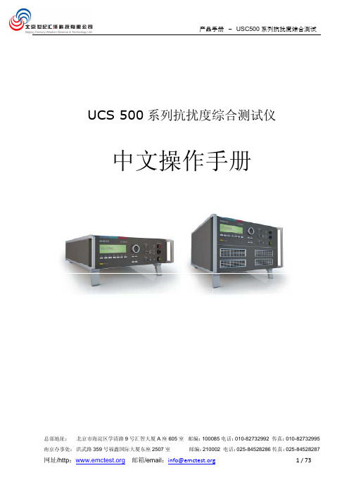
UCS 500N5 UCS 500N7系列抗扰度综合测试仪中文手册
3.1. 前面板.........................................................................................................7 3.2. 后面板.........................................................................................................9
产品手册 - USC500 系列抗扰度综合测试
UCS 500 系列抗扰度综合测试仪
中文操作手册
总部地址: 北京市海淀区学清路 9 号汇智大厦 A 座 605 室 邮编:100085 电话:010-82732992 传真:010-82732995
南京办事处: 洪武路 359 号福鑫国际大厦东座 2507 室
7.4.1. 工厂校准 .............................................................................................. 28 7.4.2. EMTEST 仪器校准周期指导 ....................................................................... 28
8. 交付件 ............................................................................................................. 29
8.1. 基本设备 .................................................................................................... 29 8.2. 附件和选件 ................................................................................................. 29
450详细安装调试说明

450详细安装调试说明⼀百多张图⽂并茂 450 详细安装调试说明此说明旨在尽量以最简单通俗易懂的语⾔来表达安装和调试过程,去掉了⼀些专业的⽤语、和⼀些复杂的调试办法,尽量使⽤最简单易学的调试⽅式,先把飞机飞起来为主。
更深⼊的调整我想只要能把飞机调试好飞起来那么以后您⾃⼰就会慢慢的领悟,进⾏更深⼊的调整和安装了。
说明中如有不妥之处还请各位⾼⼿指出,说明以便我们和更多的朋友分享。
01.jpg (46.25 KB)2009-10-14 23:1102.jpg (59.6 KB)2009-10-14 23:1103.jpg (57.84 KB)2009-10-14 23:1104.jpg (53.29 KB)2009-10-14 23:1105.jpg (58.42 KB)2009-10-14 23:1106.jpg (57.72 KB)2009-10-14 23:1207.jpg (62.2 KB)2009-10-14 23:1208.jpg (54.2 KB)2009-10-14 23:1209.jpg (54.24 KB) 2009-10-14 23:12 11.jpg (55.68 KB) 2009-10-14 23:20 12.jpg (48.43 KB) 2009-10-14 23:20 13.jpg (47.31 KB) 2009-10-14 23:20 14.jpg (80.66 KB) 2009-10-14 23:20 15.jpg (49.61 KB) 2009-10-14 23:20 16.jpg (52.8 KB) 2009-10-14 23:25 17.jpg (54.75 KB) 2009-10-14 23:25 18.jpg (55.62 KB) 2009-10-14 23:25 19.jpg (56.29 KB) 2009-10-14 23:25[本帖最后由轻风RC 于 2009-10-15 14:02 编辑] 21.jpg (52.58 KB)2009-10-14 23:2722.jpg (59.92 KB)2009-10-14 23:2723.jpg (63.7 KB)2009-10-14 23:2724.jpg (62.59 KB)2009-10-14 23:2725.jpg (49.83 KB)2009-10-14 23:2726.jpg (53.71 KB)2009-10-14 23:2827.jpg (59.49 KB)2009-10-14 23:2828.jpg (54.59 KB)2009-10-14 23:2829.jpg (59.94 KB)2009-10-14 23:2831.jpg (71.81 KB)2009-10-14 23:3032.jpg (55.28 KB)33.jpg (51.93 KB) 2009-10-14 23:3034.jpg (53.95 KB) 2009-10-14 23:3035.jpg (41.94 KB) 2009-10-14 23:30 36.jpg (61.26 KB) 2009-10-14 23:3337.jpg (57.85 KB) 2009-10-14 23:33 38.jpg (56.37 KB) 2009-10-14 23:3339.jpg (58.7 KB) 2009-10-14 23:33 41.jpg (44.28 KB) 2009-10-14 23:36 42.jpg (55.1 KB) 2009-10-14 23:36 43.jpg (49.83 KB) 2009-10-14 23:3644.jpg (60.55 KB) 2009-10-14 23:3645.jpg (57.32 KB) 2009-10-14 23:3646.jpg (49.77 KB) 2009-10-14 23:42 47.jpg (58.08 KB) 2009-10-14 23:4248.jpg (57.38 KB) 2009-10-14 23:42 49.jpg (69.23 KB) 2009-10-14 23:4251.jpg (63.7 KB) 2009-10-14 23:46 52.jpg (62.78 KB) 2009-10-14 23:4653.jpg (52.61 KB) 2009-10-14 23:46 54.jpg (55.07 KB) 2009-10-14 23:4655.jpg (39.23 KB) 2009-10-14 23:4656.jpg (36.76 KB) 2009-10-14 23:4957.jpg (75.62 KB) 2009-10-14 23:4958.jpg (71.07 KB) 2009-10-14 23:49 59.jpg (77.35 KB) 2009-10-14 23:4960.jpg (84.7 KB) 2009-10-14 23:49 61.jpg (60.28 KB) 2009-10-14 23:5162.jpg (56 KB) 2009-10-14 23:51 63.jpg (69.06 KB) 2009-10-14 23:5164.jpg (42.37 KB) 2009-10-14 23:51 65.jpg (50.57 KB) 2009-10-14 23:5166.jpg (59.45 KB) 2009-10-14 23:5368.jpg (63.17 KB) 2009-10-14 23:53 69.jpg (56.28 KB) 2009-10-14 23:5371.jpg (58.49 KB) 2009-10-14 23:56 72.jpg (58.19 KB) 2009-10-14 23:5673.jpg (63.27 KB) 2009-10-14 23:56 74.jpg (61.54 KB) 2009-10-14 23:5675.jpg (60.68 KB) 2009-10-14 23:56 76.jpg (82.44 KB) 2009-10-14 23:5877.jpg (84.03 KB) 2009-10-14 23:58 78.jpg (76.71 KB)79.jpg (56.61 KB) 2009-10-14 23:58 81.jpg (54.14 KB) 2009-10-15 00:00 82.jpg (48.65 KB) 2009-10-15 00:00 83.jpg (48.79 KB) 2009-10-15 00:00 84.jpg (51.71 KB) 2009-10-15 00:00 85.jpg (80.65 KB) 2009-10-15 00:00 86.jpg (64.32 KB) 2009-10-15 00:03 87.jpg (85.61 KB) 2009-10-15 00:03 88.jpg (86.78 KB) 2009-10-15 00:03 89.jpg (82.14 KB) 2009-10-15 00:0392.jpg (59.07 KB) 2009-10-15 00:0693.jpg (81.84 KB) 2009-10-15 00:0694.jpg (84.43 KB) 2009-10-15 00:06 95.jpg (77.66 KB) 2009-10-15 00:0696.jpg (60.64 KB) 2009-10-15 00:07 97.jpg (35.81 KB) 2009-10-15 00:0798.jpg (41.05 KB) 2009-10-15 00:07 99.jpg (44.62 KB) 2009-10-15 00:07101.jpg (64.66 KB) 2009-10-15 00:09103.jpg (55.92 KB) 2009-10-15 00:09104.jpg (55.31 KB) 2009-10-15 00:09105.jpg (52.72 KB) 2009-10-15 00:09 106.jpg (42.17 KB) 2009-10-15 00:10107.jpg (64.94 KB) 2009-10-15 00:10 108.jpg (48.27 KB) 2009-10-15 00:10109.jpg (47.06 KB) 2009-10-15 00:10 111.jpg (24.13 KB) 2009-10-15 00:12 112.jpg (52.71 KB) 2009-10-15 00:12 113.jpg (60.52 KB) 2009-10-15 00:12115.jpg (70.01 KB) 2009-10-15 00:12116.jpg (70.91 KB) 2009-10-15 00:14117.jpg (50.71 KB) 2009-10-15 00:14 118.jpg (62.84 KB) 2009-10-15 00:14119.jpg (54.37 KB) 2009-10-15 00:14 121.jpg (65.06 KB) 2009-10-15 00:18 122.jpg (34.26 KB) 2009-10-15 00:18 123.jpg (54.28 KB) 2009-10-15 00:18 124.jpg (45.66 KB) 2009-10-15 00:18 125.jpg (37.03 KB) 2009-10-15 00:18 126.jpg (36.44 KB)2009-10-15 00:18安装基本结束,剩余的飞⾏前调试就很简单了,⼀般⽂字性说明就能说清楚。
现场临时用电绝缘电阻测试记录8.5.8

现场临时用电绝缘电阻测试记录8.5.8表8.5.8 建筑施工现场临时用电绝缘电阻测试记录工程名称:南京高淳碧桂园一期A标段仪表名称兆欧表工作电压220/380V设备名称43#塔吊型号规格QTZ63回路编号阻值阻值阻值阻值阻值阻值阻值阻值阻值A B 450 390 440 460 480 470B C 480 460 450 470 490 470C A 450 460 470 500 460 500A O 500 490 430 480 500 430B O 480 480 460 490 470 490C O 500 490 480 500 490 480测试结果合格合格合格合格合格合格2013.12 2014.1 2014.2 2014.3 2014.5 2014.6测试时间测试人注:绝缘电阻值由建筑电工测试,每月复测一次。
表8.5.8 建筑施工现场临时用电绝缘电阻测试记录工程名称:南京高淳碧桂园一期A标段仪表名称兆欧表工作电压220/380V设备名称44#塔吊型号规格QTZ63回路编号阻值阻值阻值阻值阻值阻值阻值阻值阻值A B 450 460 480 480 470 450B C 490 480 460 490 460 450C A 480 500 490 500 490 480A O 480 500 430 480 500 430B O 500 490 480 500 480 490C O 490 500 480 450 490 500测试结果合格合格合格合格合格合格测试时间测试人注:绝缘电阻值由建筑电工测试,每月复测一次。
工程名称:南京高淳碧桂园一期A标段仪表名称兆欧表工作电压220/380V设备名称45#塔吊型号规格QTZ63回路编号阻值阻值阻值阻值阻值阻值阻值阻值阻值A B 480 480 440 480 460 450B C 460 480 490 490 470 450C A 480 460 480 440 490 480A O 490 500 480 480 500 450B O 470 500 500 500 450 480C O 490 500 480 450 490 500测试结果合格合格合格合格合格合格2013.12 2014.1 2014.2 2014.3 2014.5 2014.6 测试时间测试人注:绝缘电阻值由建筑电工测试,每月复测一次。
互感器伏安特性说明书

前言尊敬的用户,非常感谢您选择使用长沙威克电力技术科技有限公司的MF330互感器多功能测试仪系列产品,为了保护设备及人身安全,做实验前请仔细阅读使用说明书,严格按说明书规范操作。
MF330互感器多功能测试仪是长沙威克电力技术科技有限公司按照国家有关标准和规定,在认真分析用户需求的基础上,积累开发及运行经验,经过多次优化而设计出的伏安特性试验仪器设备。
长沙威克电力技术科技有限公司是专业从事电力测试设备开发、生产和销售的高科技产业公司。
公司经济基础雄厚,技术实力强大,勇于开拓创新。
作为电力行业的新兴力量,公司本着以技术为依托、质量为生命、服务为根本的企业宗旨。
涉足了励磁测试、二次测试、CT测试、直流系统测试等多个领域,短时间内研发出了VIC多功能电气参数测试仪,以强大的功能、简洁的操作、稳固的质量一举填补了国内电力技术的又一项空白。
同时公司研发的继电保护测试仪、伏安特性测试仪、开关特性测试仪等已达到国内一流水平。
公司一贯遵循“技术领先,品质优良,服务至上”的宗旨,竭诚为全国电力系统提供别具特色的优良产品。
第一章装置主要技术特点MF330互感器多功能测试仪是继电器保护和高压绝缘专业用来测试电流互感器和电压互感器的专门检测仪器特点如下:全自动型测试仪只要设定最高输出电压和最大输出电流,不需设置记录步长,仪器即可从零开始自动升压或升流进行各种试验。
试验中自动记录测试数据、描绘伏安特性数据、10%和5%误差曲线,并自动计算拐点值。
省去了手动调压、人工记录整理、描曲线等烦琐步骤,极大的提高了测试效率。
试验结果可以储存在机内,可以现场打印、事后打印,也可用U盘取出传至电脑处理打印。
操作快捷、简单、方便,容易掌握。
功能全面装置所具备的功能如下:1:CT伏安特性测试仪部分的要求:能测量显示打印电流互感器的“伏安特性曲线”.能测量电流互感器的“拐点”和“饱和点”,测量拐点和饱和点的励磁电压和电流。
提供测量电源,外配升压器,电流量程0—2A,电压0—2500V。
Omega CA450 过程多功能测试器说明书

Q-1QU 4 to 20 mA Step,0 to 100% Toggle, Auto Step, Sweep Output U T ransmitter Simulate by SINK Function U H ART ® Mode Setting with Loop Power (Adds 250Ω Resistor)U 24V Loop Power Supply and mAMeasurement Available Simultaneously U H igh AccuracyMeasurement of DC mA 0.05%, 30.000 mA U D CS Power Supply Crest ValueMeasurement by Peak Hold Function U D irect Reading (ACA/DCA) of Various Signals by Sensor Mode U D ata Transmission by PC Communication with IR-USB*Process MultimeterLoop Power, 4 to 20 mA Digital Multimeter Output FunctionThe Omega ® Ca450 Process multimeter is a portable test instrument to combine a digital RmS multimeter and a loop calibrator to give processtechnicians the same functionality in one tool. The model Ca450provides 24V loop power, reducing the need for carrying a separate power supply when performing transmitter testing. and with its built-in, selectable 250Ω HaRT resistor, it also eliminates the need for a separate resistor. Process technicians can now do the same job while carrying less equipment.CA450 shown smaller than actual size.CA450 shown calibrating a tunable diode laser during a final inspection test.* For details visit /ir-usbQ-2OMEGACARE SM extended warrantyprogram is available for models shown on this page. Ask your sales respresentative for full details when placing an order.OMEGACARE SM covers parts, labor andequivalent loaners.Q-3QOrdering Example: CA450, process multimeter with loop power and 4 to 20 mA output function.OCW-2, OMEGACARE SM extends standard warranty to an additional two years.SpecificationsMeasurement Functions: DC voltage, aC voltage, DC current, resistance, frequency, continuity check, diode test; data hold (D•H), auto hold (A•H), peak hold (P•H), auto range (Auto), range hold (range hold), maximum, minimum, and average value recording and measurement, zero adjustment (q), relative measured value display (ReL, ReL %), 24V loop power supply, internal resistor on/off for HaRT communicationOutput Functions: 20 am DC current for current output SOURCe and current output SImULa Te (SINK); current span switching and current sweep outputMeasurement Operation Method: modulationOutput: multiplicative DaDisplay: 5-digit LCD (7 segment)Numeric Display, DC Current: Measurement: 33000 Output: 25000 Frequency: 19999 Other: 6600Sub Display: Displayssupplemental information for various functionsPolarity Indicator: automatic display; only the minus sign “–” appears Over Range Indicator: “OL ”Low-Battery Indicator: appears when the battery voltage is below the operating voltageMeasurement Cycle:2.5 to 5 times a second (however, frequency measurement takes place once a second)Operating Temperature and Humidity: -20 to 55°C (-4 to 131°F) (80% RH or less) with no condensation; within the range of 40 to 55°C (104 to 131°F), the humidity must be 70% RH or lessS torage Temperature and Humidity: -40 to 70°C (-40 to 158°F) (70% RH or less) with no condensationTemperature Coefficient (Typical): In the ranges of -20 to 18°C (-4 to 64.4°F) and 28 to 55°C(82.4 to 131°F), add the accuracy of 23°C ± 5°C × 0.1/°CPower Supply: 4 “aa” alkaline batteries (1.5 V LR6) includedBattery Life: When using alkaline batteriesDC Voltage Measurement: approximately 140 hoursDC Current Output (SIMULATE): approximately 140 hoursDC Current Output (SOURCE) 12 mA (500 q load): approximately 10 hoursInsulation Resistance: 100 m Ω or greater at 1000 VdcWithstand Voltage: 6.88 kVac for five seconds (between the input terminals and the case)External Dimensions: approximately 90 W x 192 H x 49 mm D (3.5 x 7.5 x 1.9")Weight: approximately 600 g (1.3 lb)(including the batteries)Safety Compliant Standards: eN61010-1 and eN61010-031Measurement Categories: 1000V Ca TIII, 600V Ca TIVFor Current Measurement and Output: 48 V maximum, 100 ma maximum Ca T ILead Cables (98064): 70 Vdc, 100 ma CaT I; pollution degree 2, indoor use Vibr ation: Sweep vibrationfrequencies 10 to 5 Hz to 10 Hz; amplitude 0.15 mm (peak value); duration 30 minutesShock: 1 m (3.3') drop test as defined by safety standardsAltitude: 2000 m (6562') or less EMC Standards: eN61326-1 Class B, eN61326-2-2; eN55011 Class B group 1; influence of radiatedimmunity: In RF electromagnetic fields of 3 V/m EN61326-1:AC Voltage Measurement, 600 mV Range: 1.5% of range DC Voltage Measurement, 600 mV Range: 1% of range DC Current Measurement, All Ranges: 1.5% of rangeDC current Output: 1.5% of range EN61326-2-2:AC/DC Voltage Measurement, 6V Range or Higher:Within 5 times the accuracy。
无线电发射设备型号核准检测的检验依据(含参考标准)
无线电发射设备型号核准检测的检验依据(含参考标准)(一)调频收发信机1.国家无线电管理委员会办公室文件《关于350 MHz频段移动通信设备主要技术指标的通知》(国无办频〔1996〕93号)使用频段:336-399.9MKz(1)360MHz:基站发射频段:361-368MHz移动台发射频段:351-358MHz同频单工频段:358-361MHz(2)380MHz:基站发射频段:382-389MHz移动台发射频段:372-379MHz同频单工频段:379-382MHz2.《关于重新调整336-399MHz频段移动通信频率配置及管理办法的通知》(信无函【2001】85号)频率配置: 频率配置分为12.5kHz信道间隔和25kHz信道间隔两种方式频率分配及审批管理:(1)部门规划使用频率: 1)351-356MHz/361-366MHz2)356-358MHz/366-389MHz3)376-379MHz/386-389MHz4)358-361MHz5)379-380.5MHz上述各段频率由信息产业部无线电管理局分别配给军队、武警部队和公安系统,用于组建各系统指挥调度通信网。
(2)共用组网频率: 1.372-376MHz/382-386MHz2.380.5-382MHz上述二段频率主要分配给国家安全、法院、检察院、司法监狱劳教、海关等政府部门用于组建区域性或全国指挥调度通信网,原则上异频单工频段管理用于建设各部门共用网。
3.信息产业部《关于公众对讲机管理有关问题的通知》(信部无【2001】869号)工作频率(单位:MHz):409.7500; 409.7625; 409.7750; 409.7875; 409.8000;409.8125; 409.8250; 409.8375; 409.8500; 409.8625;409.8750; 409.8875; 409.9000; 409.9125; 409.9250;409.9375; 409.9500; 409.9625 ;409.9750; 409.9875。
安全性能综合测试仪使用手册

安全性能综合测试仪(42系列)使用手册检定规程:JJG984—2004 国家接地电阻测试仪计量检定规程JJG795—2004 国家耐电压测试仪计量检定规程JJG1005-2005 国家电子式绝缘电阻表计量检定规程JJG 843-2007《泄漏电流测试仪计量检定规程》执行标准:Q/0205OSD001—2009 96系列安全性能测试仪企业标准目录第一章安全规则 (1)1.1一般规定 (1)1.2维护和保养 (2)1.2.1使用者的维护 (2)1.2.2定期维护 (2)1.2.3使用者的修改 (2)1.3测试工作站 (3)1.3.1位置选择 (3)1.3.2输入电源 (3)1.3.3工作场所 (3)1.4操作人员规定 (3)1.4.1人员资格 (3)1.4.2安全守则 (4)1.4.3衣着规定 (4)1.4.4医学规定 (4)1.5测试安全程序规定 (4)1.6安全要点 (4)第二章概述 (5)2.1产品简介 (6)2.2产品特点 (6)2.2.1 测试迅速 (6)2.2.2 输出方式先进 (6)2.2.3 运行可靠 (6)2.2.4 操作简单 (7)2.2.5 联机方便 (7)2.3前面板说明 (7)2.4后面板简介 (9)2.4.1柜式综合测试仪后面板 (9)2.4.2台式综合测试仪后面板 (10)2.5 隔离电源输入板(只适用于柜式综测): (11)第三章安装要点 (12)3.1拆封和检查 (12)3.2使用前的准备 (12)3.2.1工作电压的要求和选择 (12)3.2.2输入电压的要求和选择 (12)3.3储存和运输 (13)3.3.1周围环境 (13)3.3.2包装方式 (13)第四章技术指标 (14)4.1整机规格 (15)4.2技术参数 (15)4.2.1接地电阻 (15)4.2.2绝缘电阻 (16)4.2.3耐压测试 (16)4.2.4泄漏电流 (17)4.2.5功率测试 (17)4.2.6启动测试 (18)第五章综合测试仪使用方法 (19)5.1外部接线 (21)5.2测试仪开机 (22)5.3自检 (22)5.4主菜单界面 (23)5.5功能设置 (24)5.5.1设置密码: (24)5.5.2单步测试: (25)5.5.3模拟阻抗(需定制): (25)5.5.4 波特率 (25)5.6密码输入 (25)5.7选择测试组 (26)5.8设置测试项 (27)5.8.1测试方式选择 (28)5.8.2测试频率选择 (28)5.8.3保存设置 (28)5.8.4不保存退出设置 (28)5.9接地测试 (29)5.9.1设置接地测试项 (29)5.9.2开始接地测试 (30)5.10绝缘测试 (30)5.10.1设置绝缘测试项 (30)5.10.2开始绝缘测试 (32)5.11耐压测试 (32)5.11.1设置耐压测试项 (32)5.11.2开始耐压测试 (34)5.12泄漏测试 (34)5.12.1设置泄漏测试项 (34)5.12.2 开始泄漏测试 (36)5.13 功率测试 (36)5.13.2 开始功率测试 (39)5.14 启动测试 (39)5.14.1 设置启动测试项 (39)5.14.2开始启动测试 (40)5.15 测试 (41)5.16串行通信 (41)5.17 遥控接口: (44)5.18 关机 (44)第六章维护指南 (45)6.1 首次使用前检查 (45)6.2 日常维护 (45)6.3 简单故障处理 (46)6.4 注意事项 (47)附录1:综合测试仪校准方法 (47)1、引言 (47)2、检定方法 (47)2.1耐电压测试的检定 (48)2.2绝缘电阻测试的检定: (49)2.3接地电阻测试的检定: (50)2.4泄漏电流测试的检定: (51)第一章安全规则本章概要:1.一般规定2.维护和保养3.测试工作站4.操作人员规定5.测试安全程序规定6.安全要点1.1一般规定∙手册内容若有改变,恕不另行通知。
737NG发动机引气系统原理及测试
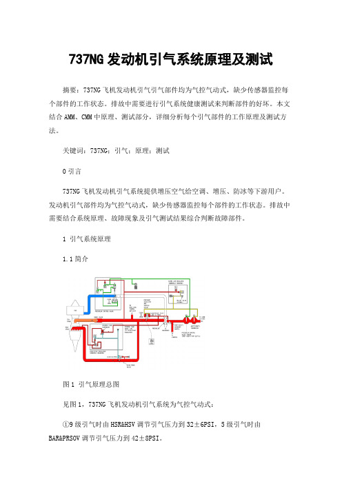
737NG发动机引气系统原理及测试摘要:737NG飞机发动机引气引气部件均为气控气动式,缺少传感器监控每个部件的工作状态。
排故中需要进行引气系统健康测试来判断部件的好坏。
本文结合AMM、CMM中原理、测试部分,详细分析每个引气部件的工作原理及测试方法。
关键词:737NG;引气;原理;测试0引言737NG飞机发动机引气系统提供增压空气给空调、增压、防冰等下游用户。
发动机引气部件均为气控气动式,缺少传感器监控每个部件的工作状态。
排故中需要结合系统原理、故障现象及引气测试结果综合判断故障部件。
1 引气系统原理1.1简介图1 引气原理总图见图1,737NG飞机发动机引气系统为气控气动式:①9级引气时由HSR&HSV调节引气压力到32±6PSI,5级引气时由BAR&PRSOV调节引气压力到42±8PSI。
②BAR&PRSOV:发动机运转前PRSOV弹簧力加载在全关位。
发动机启动后BAR的PS管有压力→引气电门ON位→BAR的PC管有压力→PRSOV在PC的压力下打开。
PRSOV开度随BAR调节的PC压力及下游引气压力大小变化。
③450℉控制器:放掉BAR的PC气,以减小PRSOV开度。
450℉时开始打开,490℉时全开。
④HSR&HSV:发动机运转前HSV弹簧力加载在全关位。
低转速时HSR的PS管有压力→HSR调节后输出PC→HSV在PC压力下打开。
HSV开度随HSR调节的PC压力大小变化。
⑤PCCV:弹簧加载全开位,管道有气后关闭。
管道温度达到390℉时由390℉控制器放掉PC气控制PCCV打开。
1.2 引气压力调节部分图2 引气压力调节见图2,引气压力调节由BAR、PRSOV、450℉控制器、490℉超温电门实现:①基准压力调节器:感应PRSOV上游管道压力,调节到24.5PSI供往PRSOV打开腔,克服PRSOV弹簧力及关闭腔压力打开PRSOV。
②释压活门:在基准压力调节器的压力大于28PSI时放气,防止通往PRSOV的PC压力过大。
试验仪器使用说明书

YAW-300E试验机一、简介YAW-300E型全自动抗压抗折试验机主要用于水泥材料的抗压抗折强度试验,也用于其他材料的抗压性能试验。
二、主要性能特点:1、220V供电,实验室电源布局方便。
2、伺服电机驱动,与传统油压方式的相比,无漏油、阀卡死等弊病。
3、零噪音。
4、负荷传感器测力,精度高,测量范围可达全量程的2%-100%.5、与传统液压方式的相比,不用年年换油,省去换油费用,且无易损件,性价比高。
三、主要性能技术指标1、最大试验力kN:300kN(抗压)10kN(抗折)2、试验力测量范围kN:2%-100%FS3、试验力示值相对误差:≤示值的±1%4、试验力分辨率:0.01kN5、加荷速率:0.3KN/S~10KN/S(抗压)50N/s(抗折)6、加荷速度误差:±5%7、上下承压板尺寸:φ155mm(抗压)80X150mm(抗折)8、上下压板间最大间距:260mm9、丝杠行程:100mm10、伺服动机功率:单相-200V , 0.75 kW11、主机外形尺寸㎜:600×560×1500mm12、重量:400Kg四、装箱单1、试验机主机1台2、联想电脑1台3、黑白喷墨打印机1台4、控制仪1台5、压盘1套6、抗折夹具1套7、使用说明书1份8、合格证1份9、装箱单1份HJW-60小型混凝土搅拌机HJW-60强制式单卧轴混凝土搅拌机功能特点:使各组成成分宏观与微观上均匀,破坏水泥颗粒团聚现象,促进弥散现象的发展,破坏水泥颗粒表面的初始水化物薄膜包裹层,促使物料颗粒间碰撞摩擦,减少灰尘薄膜的影响。
混凝土搅拌机是把水泥、砂石骨料和水混合并拌制成混凝土混合料的机械。
主要由拌筒、加料和卸料机构、机架和支承装置等组成。
按工作性质分间歇式(分批式)和连续式;按搅拌原理分自落式和强制式。
强制式单卧轴混凝土搅拌机的维护保养:1 保养机体的清洁,清除机体上的污物和障碍物。
2 检查各润滑处的油料及电路和控制设备,并按要求加注润滑油。
各种检验测试仪器使用说明

各种检验测试仪器使用说明仪器使用说明书一、产品介绍本产品为一款多功能检验测试仪器,可用于多种领域的测试和检验,包括但不限于电子产品、机械设备、化工产品等。
该仪器具有精准的测量功能和快速的检测速度,适用于各种环境和场合。
二、产品特点1.多功能性:本产品可以进行多种测试和检验,包括温度、压力、电流、电压等多个参数的测量。
2.灵活性:该仪器具有多种测量模式和参数设置功能,可根据用户需求进行调整。
3.高精度:本产品采用先进的传感技术和数据处理算法,测量精度高,数据可靠。
4.易操作性:该仪器操作简单,界面友好,适用于各种用户。
5.稳定性:本产品具有稳定的性能和可靠的品质,长时间使用不易出现故障。
三、使用说明1.开机操作:将电源插头插入电源插座,按下电源开关,待仪器显示屏亮起后,表示已开机成功。
2.参数设置:在显示屏上选择所需测量参数和模式,通过上下左右方向键进行调整,按下确认键确定设置。
3.测量操作:将待测物品连接到仪器相应接口处,按下测量键进行测量,待仪器显示测量结果后,可进行数据记录或保存。
4.关机操作:长按电源开关键,待显示屏熄灭后,表示已成功关机。
四、注意事项1.请勿将本产品暴露在潮湿、高温、高压等恶劣环境下使用,以防损坏仪器和影响测量精度。
3.使用本产品时请注意安全,避免发生意外事故。
4.每次使用后,请及时清洁和保养仪器,以确保性能稳定和寿命延长。
五、维护保养1.定期检查本产品的接线和接口是否松动,如有问题请及时处理并调整。
2.定期清洁本产品的表面和显示屏,以保持清洁和美观。
3.如长时间不使用本产品,请将其存放在干燥通风的环境中,避免受潮或受潮引起故障。
Aeroflex IFR 3900系列测试设备操作指南说明书

The AutoTest facility in the Aeroflex IFR 3900 series testOVERVIEWC r e a t i n g a n A u t o T e s t s c r i p tA 3900 AutoTest script takes the form of a flat (unformatted) text file as created, for example, on a PC using Microsoft ®Notepad.Whichever editor you use, it is important not to apply any format-ting (such as font selection). Note that the test set requires AutoTest script files to have the extender .ats so, when saving the file in Notepad, be sure to (a) specify the extender in File name :as '.ats', and set Save as type: to 'All Files'. If you leave Save as type : at the default value of 'Text Documents (*.txt)', then the file may be saved with the extender '.ats.txt' and, in that form, will not be recognized by the test set.The file can be transferred to the test set on a USB memory stick or floppy disk, from which it can be imported via the UTILS menu (UTILS / File Management / AutoTest / Scripts / Import) (Fig 1)Fig 1: Importing an AutoTest script from floppy diskRunning a scriptTo run an AutoTest script, it is first necessary to load the 3900's AutoTest system. Press the CONFIG key twice, navigate via the ARROW keys to highlight Systems / AutoTest , and press SELECT .Inside AutoTest, press the Load Script softkey, and highlight and select the required script. (Fig 2)Fig 2: Importing an AutoTest script from floppy disk Before running the script, you can use the On Error softkey to set how AutoTest behaves if a test fails -it can (a) Pause (i.e. the oper-ator decides whether the run should continue or halt), (b) Abort (the run halts regardless), or (c) Ignore (the run, if at all possible,continue). Pause is most appropriate when the UUT is being test-ed by a skilled technician; Ignore is most appropriate for simple pre-screening applications.The screen shows the progress of the test run and any operator action is prompted. (Fig 3)Fig 3: Registration test -operator prompted to turn on the UUTStoring resultsThe results of a test run can be saved to the test set's results directory. When the test has ended, select Results / Store, and enter a filename. Results files can be exported to USB memory or floppy disk via UTILS / File Management / AutoTest / Results .On a PC they can be read by Microsoft ®WordPad orWord. If read by Microsoft ®Notepad, the line terminators used by the 3901make the text confusing to read.Results files can also be imported to the test set from USB mem-ory or floppy disk via UTILS / File Ma na gement / AutoTest /Results , and displayed in AutoTest via Results / Recall.PROGRAMMINGS c r i p t e l e m e n t sAs illustrated in Fig 4, an AutoTest script is made up of the com-mands that allow:•the appropriate system to be loaded into AutoTest (more on this later),•system parameters to be set up,•functional and parametric testing against programmable lim-its.Although most scripts will follow a simple beginning-to-end sequence, the language allows for looping around and, if required, for using different parmeter values in each pass. For example:repeat 4set_rf_gen_level {-70} {-80} {-90} {-100}test_power_level_avg endtests the power level from the UUT at four sig gen levels: -70, -80,-90 and -100 dBm.Bit Error Rate testingSince AutoTest is restricted to the TETRA MS system (and not TETRA MS T1), bit error rate (BER) testing in AutoTest requires the use of TETRA Test (TT) Mode. Currently however, not all mobiles support TT Mode. When using TT Mode, the modified form of AutoTest's registration command:test_registration test_modeshould be employed. With this, once the mobile has registered,the 3901will automatically confirm TT operation.When in TT Mode, you can test bit error rate using commands such as:test_rx_meas_ber -112.0 class0 class1 class2 test_rx_meas_rber -112.0 mer class0 class1Loading a system into AutoTestFor it to operate, the 3900 test set must be loaded with a system such as TETRA MS, TETRA BS T1, etc. As can be seen from the CONFIG / Systems menu, AutoTest itself is classed as one of those systems. H owever, when you load the AutoTest system, AutoTest itself does not have a system loaded into it.The AutoTest command for loading TETRA MS has three versions:system "TETRA MS" defaultsystem "TETRA MS"system "TETRA MS" manualand each has its own properties.1. If the script usessystem "TETRA MS" defaultthen, every time the script is run, TETRA MS is loaded and all its parameters are automatically set to the AutoTest Default Values listed in the 3900 Operating Manual, Chapter22.2.If the script usessystem "TETRA MS"then:•on the first run, AutoTest loads TETRA MS and all its parame-ters are automatically set to the AutoTest Default Values.•on subsequent runs, AutoTest will not load TETRA MS and the script will start with all its parameters set as they currently stand (i.e. however they were left after the previous run).3.If the script usessystem "TETRA MS" manualthen, every time the script is run, TETRA MS is loaded and all its parameters are automatically set to the values saved when TETRA MS was last used manually(i.e. outside AutoTest).The significance of the three commands is as follows:1. system "TETRA MS" default is the most straightforward.Knowing that every run will start with all parameters set to known defaults, the writer simply has to include a relatively small number of setup statements to suit the requirements of the Unit Under Test (UUT).Loading a system adds several seconds to the run time. However, if the time penalty of loading TETRA MS on every run is not a critical issue, the relative simplicity of using system "TETRA MS" default can be attractive, to R& D experimenters looking for a quick way of creating automated test sequences. For example code, see Appendix1, Example 1.2. Since the TETRA MS system is loaded only once, usingsystem "TETRA MS"significantly reduces overall run time.However, the script must include statements not only to modi-fy AutoTest defaults to suit the UUT, but also to re-set any parameters that are modified during a run. Fortunately, the additional run time of the extra setup statements is negligible compared with the time saved by loading the TETRA MS sys-tem only once. S S o,i f y o u p l a n t o r u n t h e s a m e s c r i p t t w o o r m o r e t i m e s c o n s e c u t i v e l y,t h e n system "TETRA MS"i s t h e c o r r e c t c h o i c e.See Example 2.3. It should be noticed that scripts using either of the above twosystem commands effectively have all their parameters hard-coded, thus making them specific to the UUT type. The third command, system "TETRA MS" manual, provides for the creation of 'generic' (non UUT-specific) scripts. Such scripts assume the operator has already set the UUT-specific parame-ters (such as frequency plan, traffic channel, country code, net-work code, etc) before switching the test set into AutoTest.Although the number of parameters may be significant, the operator's workload (and the consequent risk of error) can be minimized by setting up the 3900's store-and-recall facility with the parameters for each UUT type.As with system "TETRA MS" default, system "TETRA MS" manual has the time overhead of always loading the TETRA MS system. However, the ability to use a single script on mobiles that are set up for different channels, etc, may have an overriding attraction to, say, a repair organization. SeeExample 3.Fig 4: Example script structureFor the very latest specifications visit Appendix1: Example AutoTest scriptsEach of the following three examples follow the same pattern of testing: the mobile is registered with the 3901test set, a call is placed, a few parameteric tests are carried out, and the call is closed.Examples 1and 2are each dedicated to a particular Channel Plan, Mobile Country Code and Mobile Network Code. It will be necessary to adjust these values to suit the mobile under test. All that is necessary to do is edit the values given in the Setup UUT-SPECIFIC parameters: section.By contrast, Example 3is generic, requiring the operator to set up those parameters manually in the 3901's TETRA MS mode prior to invoking AutoTest. In addition, Example 3illustrates the use of TT Mode to enable BER tests to be made. If the moble in ques-tion does not support TT Mode, then the BER and RBER tests should be removed and the test_registration statement should be modified in line with Examples 1and 2.Soft copies of the latest versions can be found on the 3900 App Notes pages at /tetra/3900scripts.zip.Example 1This example uses s s y s t e m"T E T R A M S"d e f a u l t to guarantee all parameters revert to default values at the start of every test run -but at the cost of running time. It is dedicated to a particular channel, MCC and MNC.Summary CommentType:UUT-specific Hard coded channels, MCC,MNC, etc.Foolproof:Yes Operator has no influence onparameters.Run time:Slow TETRA MS system reloadedon every run.Notes:Script starts with default values on every run.# Simple_800Band_AutoDefaultVals.ats# March 2005# 3900 AUTOTEST script to register a mobile# (in test mode), place a call from the# mobile, measure TX parameters, and close# the call from the testset.# This script assumes the values specified# in 'Setup UUT-SPECIFIC parameters', below.# ########################################### LOAD TETRA MS AND SET UP SYSTEM PARAMETERS # ########################################### Load TETRA MS system, using default# parameters on every run:system "TETRA MS" default# Setup TEST-SPECIFIC parameters:set_registration_timeout 60set_group_attach_wait 1# Setup UUT-SPECIFIC parameters:set_channel_plan "TETRA 805-870 +12.5"set_control_channel 2040set_traffic_channel 2140set_tch_timeslot 3set_MCC 1set_MNC 00001# ########## RUN TESTS# ########## Register mobile:set_rf_gen_level -75.0test_registration# Mobile-originated call:test_mobile_call phone# Tx tests:test_burst_timing_wctest_power_level_avgtest_power_profiletest_freq_error_wctest_vector_error_rms_maxtest_vector_error_peak_maxtest_residual_carrier_max# Close call from test set:test_testset_clearExample 2This example uses s s y s t e m"T E T R A M S"to minimize overall run time. As in Example 1, this script is dedicated to a particular chan-nel, MCC and MNC.Summary CommentType:UUT-specific Hard coded channels, MCC,MNC, etc.Foolproof:Yes Operator has no influence onparameters.Run time:Fast TETRA MS system loadedonly on first run after loadingthe script.Notes:Script starts with default values on first run.Script writer has to reset only those parametersthat change during a run.# Simple_800Band_NoDefaultVals.ats# March 2005# 3900 AUTOTEST script to register a mobile, # place a call from the mobile, measure TX# parameters, and close the call from the# testset.# This script assumes the values specified# in 'Setup UUT-SPECIFIC parameters', below.# ########################################### # LOAD TETRA MS AND SET UP SYSTEM PARAMETERS: # ########################################### # If this is the first run since loading this # script, then load TETRA MS using default# parameters:system "TETRA MS"# Restore any parameters that are altered# during the test run:set_rf_gen_level -75.0# Setup TEST-SPECIFIC parameters:set_registration_timeout 60set_group_attach_wait 1# Setup UUT-SPECIFIC parameters:set_channel_plan "TETRA 805-870 +12.5"set_control_channel 2040set_traffic_channel 2050set_tch_timeslot 3set_MCC 400set_MNC 3# ########### RUN TESTS:# ########### Register mobile:test_registration# Mobile-originated call:test_mobile_call phone# Tx tests:test_burst_timing_wctest_power_level_avgtest_power_profiletest_freq_error_wctest_vector_error_rms_maxtest_vector_error_peak_maxtest_residual_carrier_max# Close call from test set:test_testset_clearExample 3The previous examples, by setting-up all parameters prior to test-ing the UUT, are dedicated to testing on a particular channel, MCC, MNC, etc. By contrast, this example uses s s y s t e m"T E T R A M S"M a n u a l as a means of generating a generic script. However, it assumes that the operator manually sets up the test set appro-priate to this UUT before selecting AutoTest and running the script.Summary CommentType:Generic Operator sets parameterswith normal 3900 manualscreens immediately before Foolproof:No selecting AutoTest.Run time:Slow TETRA MS system reloadedon every run.Notes:Script starts with (operator pre-set) values onevery run.# Simple_Generic_TTMode_ManualVals.ats# March 2005# 3900 AUTOTEST script to register a mobile# (in test mode), place a call from the# mobile, measure TX and Rx parameters, and# close the call from the testset.# This script assumes:# 1. The UUT supports TT mode.# 2. The operator manually sets-up the test# set appropriate to the UUT before# selecting AutoTest, loading this script # and running it.# ########################################### # LOAD TETRA MS AND SET UP SYSTEM PARAMETERS: # ########################################### # On every run, load TETRA MS system using# values as saved when TETRA MS was last used # manually (i.e. outside AutoTest):system "TETRA MS" manual# Setup TEST-SPECIFIC parameters:set_registration_timeout 60set_group_attach_wait 1# ########### RUN TESTS:# ########### Register mobile, confirm in TT mode:test_registration test_mode# Mobile-originated call:test_mobile_call phone# Tx tests:test_burst_timing_wctest_power_level_avgtest_power_profiletest_freq_error_wctest_vector_error_rms_maxtest_vector_error_peak_maxtest_residual_carrier_max# Rx tests:test_rx_meas_ber -112.0 class0 class1 class2 test_rx_meas_rber -112.0 mer class0 class1# Close call from test set:test_testset_clearFor the very latest specifications visit Appendix2: Code to set TETRA MS AutoTest DefaultsThe following code sets all TETRA MS AutoTest parameters to the AutoTest Default values listed in Chapter22of the 3900 Operating Manual. By pasting all or part of this code into your test scripts, and selectively adjusting values, you can minimize the effort involved in the setting up of test parameters. Soft copy of the latest version can be found on the 3900 App Notes pages at /tetra/3900scripts.zip.Commands are grouped in functional blocks, resulting in some (such as set_ptt_timeout and set_traffic_channel) appearing more than once.For the purposes of this application note, (+++) indicates that a long command has been wrapped around. In reality, AutoTest commands cannot be continued onto another line.# Name: 3900_TETRA_MS_All_Defaults.txt# Date: May 2005# The following code sets all TETRA MS# AutoTest parameters to the AutoTestDefault# values listed in Chapter 22 of the 3900# Operating Manual.# It is not a complete test script.However,# it is intended as a typing shortcut, to be # pasted, all or in part, into users' own# scripts with values altered as required.# ############################### Setting default parameters ...# ############################### Default GENERAL parameters:set_rf_ana_control_mode expectedset_rf_ana_port trset_rf_ana_level_offset_enable offset_rf_ana_level_offset_value 0.0set_rf_ana_expected_level +30.0set_rf_gen_level -75.0set_rf_gen_port trset_rf_gen_level_offset_enable offset_rf_gen_level_offset_value 0.0set_timing_offset_enable offset_timing_offset_value 0.0# Default IN CALL parameters:set_idle_channel message facchset_rf_ana_control_mode open# Default POWER LEVEL test parameters:set_power_class 4set_power_class_usage reportedset_power_level_limits +2.0 -2.0 +2.5 -2.5set_power_samples 20set_ptt_timeout 20# Default POWER PROFILE test parameters:set_power_profile_limits -70.0 -36.0 +6.0+3.0set_ptt_timeout 20# Default BURST TIMING test parameters:set_burst_timing_limit 0.25set_burst_timing_samples 20set_ptt_timeout 20# Default FREQUENCY ERROR test parameters: set_freq_error_limit 100set_freq_error_samples 20set_ptt_timeout 20# Default VECTOR ERROR RMS test parameters: set_vector_error_rms_limit 10.0set_vector_error_rms_samples 20set_ptt_timeout 20# Default VECTOR ERROR PEAK test parameters: set_vector_error_peak_limit 30.0set_vector_error_peak_samples 20set_ptt_timeout 20# Default RESIDUAL CARRIER test parameters: set_residual_carrier_limit 5.0set_residual_carrier_samples 20set_ptt_timeout 20# Default RX MEAS - BER test parameters:set_BER_class0_limits 4.27 4.88 4.27set_BER_class0_samples 15000set_BER_class1_limits 0.23 0.23 0.23set_BER_class1_samples 15000set_BER_class2_limits 0.23 0.23 0.23set_BER_class2_samples 15000set_rx_class Aset_rx_class_usage reportedset_level_change_wait 2# Default RX MEAS - RBER test parameters:set_MER_limits 0.045 0.045 0.045set_MER_samples 300set_RBER_class0_limits 4.27 4.88 4.27set_RBER_class0_samples 15000set_RBER_class1_limits 0.23 0.23 0.23set_RBER_class1_samples 15000set_rx_class Aset_rx_class_usage reportedset_level_change_wait 2# Default REGISTRATION test parameters:set_access_param -45set_base_advanced_link not_supportedset_base_air_interface_encryption not_avail-ableset_base_circuit_mode_data_service(+++) not_supportedset_base_migration supportedset_base_minimum_mode_service never_usedset_base_power_off_deregistration required set_base_power_on_registration requiredset_base_priority_cell yesset_base_reserved not_availableset_base_system_wide_services normal_modeset_base_tetra_packet_data_service(+++) not_availableset_base_tetra_voice_service supportedset_BCC 01set_channel_plan "TETRA 380-400 +12.5"set_control_channel 3600set_group_attach_wait 25set_GSSI 1set_GSSI_usage reportedset_LA 00001set_max_tx_level 30set_MCC 001set_min_rx_level_access -125set_MNC 00001set_registration_timeout 30set_SSI 00000001set_SSI_usage reported# Default PLACE CALLS FROM TEST SET# test parameters:set_emergency_call_params individual simplex(+++) direct 742200set_group_call_params 00 742200set_phone_call_params 00 "01438742200" incset_place_call_timeout 20set_place_call_typecheck yesset_private_call_params simplex hook 00742200set_tch_timeslot 3set_traffic_channel 3700set_user_call_params individual duplex hook00(+++) 16777186 "742200" inc# Default PLACE CALLS FROM MOBILE test# parameters:set_place_call_timeout 20set_place_call_typecheck yesset_tch_timeslot 3set_traffic_channel 3700# Default CALL CLEARDOWN FROM TEST SET test# parameters:# ... there are no parameters to set# Default CALL CLEARDOWN FROM MOBILE test# parameters:set_clear_call_timeout 20# Default DEREGISTRATION test parameters:set_deregistration_timeout 20# Default SPEECH QUALITY / TONE / SILENCE# test parameters:set_audio_test_timeout 20set_ptt_timeout 20# ######################################### ... finished setting default parameters.# ########################################For the very latest specifications visit 。
无线电发射设备型号核准检验标准依据
无线电发射设备型号核准检验标准依据(一)调频收发信机1. 工信部无[2009]666号《工业和信息化部关于150MHz400MHz频段专用对讲机频率规划和使用管理有关事宜的通知》2. 信部无[2001]793号《关于400MHz频段公众对讲机业务频率规划的通知》3. 信部无[2005]423号《微功率(短距离)无线电设备的技术要求》4. 国无办频[1996]93号《关于350MHz频段移动通信设备主要技术指标的通知》5. 使用频段:336 MHz~399.9MHz(1)360MHz:基站发射频段:361 MHz~368MHz移动台发射频段:351 MHz~358MHz同频单工频段:358 MHz~361MHz(2)380MHz:基站发射频段:382 MHz~389MHz移动台发射频段:372 MHz~379MHz同频单工频段:379 MHz~382MHz6. 信无函[2001]85号《关于重新调整336~399MHz频段移动通信频率配置及管理办法的通知》频率配置: 频率配置分为12.5kHz信道间隔和25kHz信道间隔两种方式频率分配及审批管理:(1)部门规划使用频率:1)351 MHz~356MHz/361 MHz~366MHz2)356 MHz~358MHz/366 MHz~389MHz3)376 MHz~379MHz/386 MHz~389MHz4)358 MHz~361MHz5)379 MHz~380.5MHz(2)共用组网频率:1)372 MHz~376MHz/382 MHz~386MHz2)380.5 MHz~382MHz7. GB/T 21646-2008《400MHz频段模拟公众无线对讲机技术规范和测量方法》8. 信息产业部《关于公众对讲机管理有关问题的通知》(信部无【2001】869号)工作频率(单位:MHz):409.7500; 409.7625; 409.7750; 409.7875; 409.8000;409.8125; 409.8250; 409.8375; 409.8500; 409.8625;409.8750; 409.8875; 409.9000; 409.9125; 409.9250;409.9375; 409.9500; 409.9625 ;409.9750; 409.9875。
Transmation QuikCal 390 校验仪是精密电子 说明书

T TransmationTransmation QuikCal 390校验仪是精密电子仪器,精确地测量和显示压强和电流信号。
另外,有手动内部开关保持测试单位能力。
底部安装插入式的压力模块和 NPT配件允许简单连接到过程校验,输入开关和电流的连接孔在显示器上方。
五个容易可替换的AA碱性电池提供更长的使用寿命和最小的更换时间。
可选择的单位允许配置所有普通工程单位。
QuikCal 390为综合Transmation过程校验设备的综合系列之一。
压力模块可互换在其他校验仪,包括 QuikCal多功能的 190系列校验仪和自动泵。
文件是非曲直设备操作和维护安全是不可缺少必备的资料,不可遗弃这些说明书。
·QuikCal 390·快,精确结果·可选择压强单位测试压强开/关可以冻结测量结果。
·测量达 0.001 mA分辨率校验你的 P/I传感变送器。
·Interchang模块能配置其他 QuikCal校验仪。
安全考虑绝对保证所有任何连接或切断的系统压力低于在制造过程中预先设定的压力。
过高的系统压力能引起严重个人的伤害或设备损害的故障。
当工作在压力装置设备附近的地方,必须实行标准的安全保护(i.e,eye保护,用手套抓,保护的衣服,等等)。
连接QuikCal 390在匣子的底部可装一个Transmation 90型模块。
此外,另一个模块插上插头经由Modpack 91以接通外部电源。
Modpack QuikCal 390附加端口通过电缆和微型-DIN连接头连接,由绝缘导线或等效导线提供电的连接。
为了连接压力,供应配件必须安在压力端口。
这端口包含1/8"-18 NPT插孔线。
1. 供给的配件以铁袱龙或以导管蒙布漆多圈绕。
2. 保证拧紧提供的配件,应用5/8"扳手定住模块端口,防止旋转。
直到供给配件拧紧。
功能键QuikCal 390 包含6个功能键:★On/Off 键:该键打开或关校验仪。
- 1、下载文档前请自行甄别文档内容的完整性,平台不提供额外的编辑、内容补充、找答案等附加服务。
- 2、"仅部分预览"的文档,不可在线预览部分如存在完整性等问题,可反馈申请退款(可完整预览的文档不适用该条件!)。
- 3、如文档侵犯您的权益,请联系客服反馈,我们会尽快为您处理(人工客服工作时间:9:00-18:30)。
6.调节气路: 首先将CV1、CV2、V1、V2、V3、V4、V6全部关闭。 打开CV2将传感器感受引起压力调节到手册要求的压力值 (观察G3和压力表) 打开CV1将传感器上游压力调节至手册要求的压力值 (观察G1表)
打开手册要求的节流阀门(一共三个)。
Maint. & Engineering Dept.
Reliability Alert Investigation
6.温度调节 温度调节在调解面 板上左侧窗口。 按一下set健之后 数显窗口闪烁,按上下 按钮调节所需温度的上 限。(上限温度手册给 出)之后再次按下set 健。 右侧窗口红色数字 显示加热器温度,绿色 数字显示加热器限制温 度(超出此温度加热器 自动切断且发出警报)
Reliability Alert Investigation
设备使用
1.安装待测航材(390或者450传感器)。 2.连接电源、气源。 3.设备厂商说明:先供气,后加热,防止加热器过热烧毁。 4.打开气源阀门并打开CV3、CV4。 5.打开加热电源
安装待测航材
Maint. & Engineering Dept.
Maint. & Engineering Dept.
Copyright © 2007 中国深圳航空有限责任公司 维修工程部
Reliability Alert Investigation
7.观察现象,当温度调节窗红色数字达到预设值时,等待 并让设备稳定5分钟(此时温度不会再上升),5分钟过后 观察G2压力表,如果航材状态完好,则传感器放气,G2压 力表压力下降,记下压力值,并对比手册要求压降压力值。 符合标准则测试通过,测试值不在标准范围内则航材故障。 压降观察窗
Maint. & Engineering Dept.
Copyright © 2007 中国深圳航空有限责任公司 维修工程部
Reliability Alert Investigation
设备原理
本设备意在模拟发动引气环境,产生高温高压气 体,从而测试390/450传感器的放气功能。 设备连接气源管路与加热电路,气源连接后,控 制盒将其分为两路,一路模拟传感器上游的控制气体, 一路模拟发动机引气管路气体。 电源连接后,电源控制盒内部有发热原件,用电 加热的方式将控制盒流出的模拟的发动机引气气体加 热。从而使得气体变成高温高压气体。
Copyright © 2007 中国深圳航空有限责任公司 维修工程部
Reliability Alert Investigation
传感器上游压 力压力观察窗
节流阀门
调节传感器上游 控制压力调节阀
模拟引起压力 调节阀
模拟引起压力 观察窗
Maint. & Engineering Dept.
Copyright © 2007 中国深圳航空有限责任公司 维修工程部
Copyright © 2007 中国深圳航空有限责任公司 维修工程部
Reliability Alert Investigation
气源循环 开ngineering Dept.
Copyright © 2007 中国深圳航空有限责任公司 维修工程部
Reliability Alert Investigation
Reliability Alert Investigation
390/450测试设备简易使用说明
Maint. & Engineering Dept.
Copyright © 2007 中国深圳航空有限责任公司 维修工程部
Reliability Alert Investigation
此设备由一个供气箱和一个加热箱组成。面板大致分为两 个,一个控制供气气路压力,一个控制加热温度。 设备的目的意在模拟390与450传感器的真实工作环境,以 测试传感器的状态。
Maint. & Engineering Dept.
Copyright © 2007 中国深圳航空有限责任公司 维修工程部
Reliability Alert Investigation
Maint. & Engineering Dept.
Copyright © 2007 中国深圳航空有限责任公司 维修工程部
Reliability Alert Investigation
后记:此设备设计还不是很成熟,培训测试 时,测试现象不是很明显,今后如有改进, 请参考新版说明。
Maint. & Engineering Dept.
Copyright © 2007 中国深圳航空有限责任公司 维修工程部
Maint. & Engineering Dept.
Copyright © 2007 中国深圳航空有限责任公司 维修工程部
Reliability Alert Investigation
390中文测试使用手册
Maint. & Engineering Dept.
Copyright © 2007 中国深圳航空有限责任公司 维修工程部
