DCX114TH-F中文资料
C1419中文资料
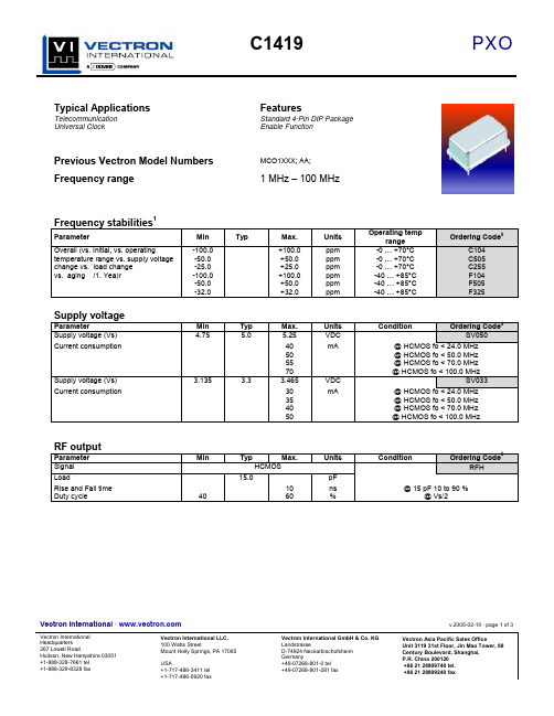
Vectron International · v.2005-02-10 · page 1 of 3Vectron International Headquarters Vectron International LLC. 100 Watts StreetVectron international GmbH & Co. KG LandstrasseVectron Asia Pacific Sales OfficeUnit 3119 31st Floor, Jin Mao Tower, 88Typical ApplicationsFeaturesTelecommunication Standard 4-Pin DIP Package Universal Clock Enable FunctionPrevious Vectron Model NumbersMCO1XXX; AA;Frequency range1 MHz – 100 MHzFrequency stabilities 1ParameterMin Typ Max. Units Operating temprange Ordering Code 5Overall (vs. Initial, vs. operatingtemperature range vs. supply voltage change vs. load change vs. aging /1. Yea)r-100.0 -50.0 -25.0 -100.0 -50.0 -32.0+100.0 +50.0 +25.0 +100.0 +50.0 +32.0ppm ppm ppm ppm ppm ppm-0 … +70°C -0 … +70°C -0 … +70°C -40 … +85°C -40 … +85°C -40 … +85°CC104 C505 C255 F104 F505 F325Supply voltageParameterMin Typ Max. Units ConditionOrdering Code 5Supply voltage (Vs)4.755.0 5.25 VDCSV050Current consumption40 50 55 70 mA@ HCMOS fo < 24.0 MHz @ HCMOS fo < 50.0 MHz @ HCMOS fo < 70.0 MHz @ HCMOS fo < 100.0 MHz Supply voltage (Vs) 3.135 3.3 3.465 VDC SV033 Current consumption30 35 40 50mA@ HCMOS fo < 24.0 MHz @ HCMOS fo < 50.0 MHz @ HCMOS fo < 70.0 MHz @ HCMOS fo < 100.0 MHzRF outputParameter Min Typ Max.Units ConditionOrdering Code 5SignalHCMOSRFHLoad15.0 pFRise and Fall time 10 ns @ 15 pF 10 to 90 %Duty cycle4060%@ Vs/2Vectron International · v.2005-02-10 · page 2 of 3Vectron International Headquarters Vectron International LLC.100 Watts StreetVectron international GmbH & Co. KGLandstrasseVectron Asia Pacific Sales OfficeUnit 3119 31st Floor, Jin Mao Tower, 88EnclosuresAbsolute Maximum RatingsParameter Min Typ Max. Units Condition Supply voltage (Vs) 7 VOperable temperature range -30 +80 °CStorage temperature range -40 +90 °CVectron International · v.2005-02-10 · page 3 of 3Vectron International Headquarters Vectron International LLC.100 Watts StreetVectron international GmbH & Co. KGLandstrasseVectron Asia Pacific Sales OfficeUnit 3119 31st Floor, Jin Mao Tower, 88How to Order this Product:Step 1 Use this worksheet to forward the following information to your factory representative:Model Stability Code Supply Voltage Code RF Output Code Package Code C1419Example: C1419 C104 SV050 RFH A1Step 2 The factory representative will then respond with a Vectron Model Number in the following Configuration: Model Package Code Dash Dash NumberC1419 [Customer Specified Package Code]- [Factory Generated 4 digit number] Typical P/N = C1419A1-0001Notes:1 Contact factory for improved stabilities or additional product options. Not all options and codes are available at all frequencies.2 Unless otherwise stated all values are valid after warm-up time and refer to typical conditions for supply voltage, frequency controlvoltage, load, temperature (25°C)3 Phase noise degrades with increasing output frequency.4 Subject to technical modification.5 Contact factory for availability.。
Pepperl+Fuchs 14 KFD2-EB2.R4A.B 重复电源模块说明书
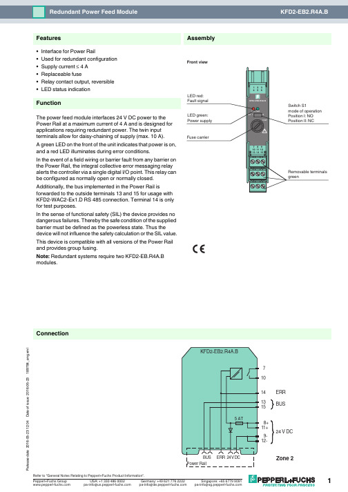
16-05-23 12:04D a t e o f i s s u e 2016-05-23189784_e n g .x m l14131571024 V DC9-12-8+11+BUSERR ConnectionAssembly•Interface for Power Rail•Used for redundant configuration •Supply current ≤ 4 A •Replaceable fuse•Relay contact output, reversible •LED status indicationFunctionThe power feed module interfaces 24V DC power to the Power Rail at a maximum current of 4A and is designed for applications requiring redundant power. The twin input terminals allow for daisy-chaining of supply (max. 10A).A green LED on the front of the unit indicates that power is on, and a red LED illuminates during error conditions.In the event of a field wiring or barrier fault from any barrier on the Power Rail, the integral collective error messaging relay alerts the controller via a single digital I/O point. This relay can be configured as normally open or normally closed.Additionally, the bus implemented in the Power Rail isforwarded to the outside terminals 13 and 15 for usage with KFD2-WAC2-Ex1.D RS 485 connection. Terminal 14 is only for test purposes.In the sense of functional safety (SIL) the device provides no dangerous failures. Thereby the safe condition of the supplied barrier must be defined as the powerless state. Thus the device will not influence the safety calculation or the SIL value.This device is compatible with all versions of the Power Rail and provides group fusing.Note: Redundant systems require two KFD2-EB.R4A.B modules.FeaturesFront view16-05-23 12:04D a t e o f i s s u e 2016-05-23189784_e n g .x mlSupplyConnection terminals 11+, 12-terminals 8+, 9-Rated voltage U n20 ... 30 V DCThe maximum rated operating voltage of the devices plugged onto the Power Rail must not be exceeded.Power dissipation ≤ 2.4 WOutputSupply Output current: ≤ 4 A Fault signal relay output: NO contactContact loading30 V AC/ 2 A / cos φ ≥ 0.7 ; 40 V DC/ 2 A Energized/De-energized delay approx. 20 ms / approx. 20 msFuse rating5 Arecommended maximum utilization of the fuse: 80 %Directive conformity Electromagnetic compatibilityDirective 2014/30/EU EN 61326-1:2013 (industrial locations)ConformityElectromagnetic compatibility NE 21:2006Degree of protection IEC 60529:2001Ambient conditions Ambient temperature -20 ... 60 °C (-4 ... 140 °F)Mechanical specifications Degree of protection IP20Mass approx. 100 gDimensions 20 x 119 x 115 mm (0.8 x 4.7 x 4.5 in) , housing type B2Mountingon 35 mm DIN mounting rail acc. to EN 60715:2001Data for application in connection with Ex-areasStatement of conformityTÜV 00 ATEX 1618 X Group, category, type of protection, temperature class ¬ II 3G Ex nA nC IIC T4Directive conformityDirective 2014/34/EU EN 60079-0:2012+A11:2013 , EN 60079-15:2010International approvals FM approval Control drawing 116-0160Approved for Class I, Division 2, Groups A, B, C, D; Class I, Zone 2, IIC UL approvalApproved for Class I, Division 2, Groups A, B, C, D; Class I, Zone 2, IIC CSA approval Control drawing 116-0160Approved for Class I, Division 2, Groups A, B, C, D; Class I, Zone 2, IIC IECEx approval IECEx UL 16.0051Approved for Ex nA nC IIC T4 Gc General information Supplementary informationStatement of Conformity, Declaration of Conformity, Attestation of Conformity and instructions have to be observed where applicable. For information see .16-05-23 12:04D a t e o f i s s u e 2016-05-23189784_e n g .x mlPower feed module KFD2-EB2The power feed module is used to supply the devices with 24 V DC via the Power Rail. The fuse-protected power feed module can supply up to 150individual devices depending on the power consumption of the devices. Collective error messages received from the Power Rail activate a galvanically-isolated mechanical contact.Power Rail UPR-03The Power Rail UPR-03 is a complete unit consisting of the electrical insert and an aluminium profile rail 35mm x 15mm. To make electrical contact, the devices are simply engaged.Profile Rail K-DUCT with Power RailThe profile rail K-DUCT is an aluminum profile rail with Power Rail insert and two integral cable ducts for system and field cables. Due to this assembly no additional cable guides are necessary.Power Rail and Profile Rail must not be fed via the device terminals of the individual devices!Accessories。
FN2410 FN2412 标准性能单相过滤器说明书

DATA SHEETStandard Performance Single-Phase Filters FN2410 and FN2412EMC/RFI Filters for Industrial ElectronicsExcellent filter performance for applications with high interference levelsFilters for two-phase supply up to 2x 520 VAC (P-P) availableFast and comfortable snap-in installation on popular TS 35 DIN-rails up to 45 A Industrial grade terminal blocks for unsurpassed electrical safetyPerformance indicatorsTechnical SpecificationsMaximum continuous operating voltage 2x 520/300 VAC (FN 2410 H/FN 2412 H)1x 250 VAC (FN 2410/FN 2412)Operating frequencyDC to 400 HzRated currents8 to 45 A @ 50°C (FN 2412)8 to 100 A @ 50°C (FN 2410)High potential test voltageP –> P 2250 VDC for 2 sec (H types)P –> E 2000 VAC for 2 sec P –> N 1100 VDC for 2 secP –> E 2700 VDC for 2 sec (H types)Protection category IP 20Overload capability4x rated current at switch on,1.5x rated current for 1 minute, once per hour Temperature range (operation and storage)-25°C to +100°C (25/100/21)Flammability corresponding to UL 94 V-2 or betterDesign corresponding toUL 1283, CSA 22.2 No. 8 1986, IEC/EN 60939MTBF @ 50°C/250 V (Mil-HB-217F)1,200,000 hours250,000 hours (H types)Approvals & CompliancesFeatures and BenefitsTypical ApplicationsFN 2410 filters up to 100 A are designed for traditional chassis mountingFor extra fast installation, FN 2412 filters up to 45 A can comfortably be snapped-in on popular TS 35DIN-rails which are common in most electrical cabinetsBoth FN 2410 and FN 2412 are also avail- able as …H versions“. These are ideally suitable for anoperation on two phases in a three-phase power network, handling voltages up to 520 VAC All filters provide an exceptional conductedattenuation performance, based on chokes with high saturation resistance and excellent thermal behavior. Thus, all filters retain the expected filter performance even in very noisy applications and under full load conditionsTouch-safe industrial grade terminal blocks provide maximum electrical safety and protect humans from undeliberate contact with life conductors. They help to fulfill the mostdemanding installation standardsSmall to medium-sized machines and industrial equipmentHigh-end single-phase power supplies Single-phase variable speed motor drives,inverters and convertersDIN-rail filter versions are ideal for panel building and electrical cabinetsVarious noisy applications with higher power single-phase or two-phase supply Typical electrical schematicFilterRated current Leakage current*Power loss Input/Output Weight@ 50°C (40°C)@ 250 VAC /50 Hz @ 25°C/50 Hzconnections(@ 120 VAC /60 Hz)[A][mA][W][kg]FN 2410-8-448 (8.8) 2.60 (1.49) 2.6-440.4FN 2410-16-4416 (17.5) 2.60 (1.49) 3.5-440.5FN 2410-25-3325 (27.4) 2.60 (1.49) 5.5-330.6FN 2410-32-3332 (35.0) 2.60 (1.49) 5.6-330.7FN 2410-45-3345 (49.3) 2.60 (1.49)7.4-330.7FN 2410-60-3460 (65.7) 2.60 (1.49) 5.5-34 1.8FN 2410-80-3480 (87.6) 2.60 (1.49)9.9-34 1.8FN 2410-100-34100 (109.5)2.60 (1.49)15.4-34 1.8FN 2410 H-8-448 (8.8) 2.60 (1.49) 2.6-440.5FN 2410 H-16-4416 (17.5) 2.60 (1.49)3.5-440.6FN 2410 H-25-3325 (27.4) 2.60 (1.49) 5.5-330.7FN 2410 H-32-3332 (35.0) 2.60 (1.49) 5.6-330.8FN 2410 H-60-3460 (65.7) 2.60 (1.49) 5.5-34 1.9FN 2410 H-80-3480 (87.6) 2.60 (1.49)9.9-34 1.9FN 2410 H-100-34100 (109.5)2.60 (1.49)15.4-34 1.9FN 2412-8-448 (8.8) 2.60 (1.49) 2.6-440.4FN 2412-16-4416 (17.5) 2.60 (1.49)3.5-440.6FN 2412-25-3325 (27.4) 2.60 (1.49) 5.5-330.7FN 2412-32-3332 (35.0) 2.60 (1.49) 5.6-330.8FN 2412-45-3345 (49.3) 2.60 (1.49)7.4-330.8FN 2412 H-8-448 (8.8) 2.60 (1.49) 2.6-440.5FN 2412 H-16-4416 (17.5) 2.60 (1.49) 3.5-440.7FN 2412 H-25-3325 (27.4) 2.60 (1.49) 5.5-330.8FN 2412 H-32-3332 (35.0)2.60 (1.49)5.6-330.9* Maximum leakage under normal operating conditions (acc. to IEC60939-3). Note: if the neutral line is interrupted, worst case leakage could reach twice this level.Filter Selection TablePer CISPR 17; A=50 Ω/50 Ω sym; B=50 Ω/50 Ω asym; C=0.1 Ω/100 Ω sym; D=100 Ω/0.1 Ω sym Typical Filter Attenuation8 to 45 A types60 to 100 A typesMechanical DataFN 2410 (H)FN 2412 (H)FN 2410FN 24128 A16 A 25 A 32 A 45 A 60 A 80 A 100 A 8 A 16 A 25 A 32 A 45 A A 130130130130130165165165110110110110110B 93939393931151151159393939393C 62627676761001001007373878787D 108108108108108140140140E 120120120120120155155155F 7070707070909090G 5.3 5.3 5.3 5.3 5.3 5.3 5.3 5.3H 1.0 1.0 1.0 1.0 1.0 1.2 1.2 1.2I 22222525253939392222252525JM6M6M6M6M6M8M8M8M6M6M6M6M6Rec. torque (Nm) 3.5 - 4.0 3.5 - 4.0 3.5 - 4.0 3.5 - 4.0 3.5 - 4.08.0 - 9.08.0 - 9.08.0 - 9.0 3.5 - 4.0 3.5 - 4.0 3.5 - 4.0 3.5 - 4.0 3.5 - 4.0L17.517.531.531.531.539.239.239.228.528.542.542.542.5All dimensions in mm; 1 inch = 25.4 mmTolerances according: ISO 2768-m/EN 22768-mDimensions-33-34-44Solid wire 16 mm 235 mm 210 mm 2Flex wire 10 mm 225 mm 2 6 mm 2AWG type wire AWG 6AWG 2AWG 8Recommended torque1.5-1.8 Nm4.0-4.5 Nm1.0-1.2 NmPlease visit to find more details on filter connectors.Filter Input/Output Connector Cross SectionsTo find your local partner within Schaffner‘s global network © 2022 Schaffner GroupThe content of this document has been carefully checked and understood.However,neither Schaffner nor its subsidiaries assume any liability whatsoever for any errors or inaccuracies of this document and the consequences thereof.Published specifica-tions are subject to change without notice.Product suitability for any area of application must ultimately be determined by the customer.In all cases,products must never be operated outside their published specifications.Schaffner does not guarantee the availability of all published products.This disclaimer shall be governed by substantive Swiss law and resulting disputes shall be settled by the courts at the place of business of Schaffner Holding test publications and a complete disclaimer can be downloa-ded from the Schaffner website.All trademarks recognized.Headquarters, Global Innovation and DevelopmentSwitzerlandSchaffner Holding AG Industrie Nord Nordstrasse 11e 4542Luterbach+41 32 681 66 26******************Sales and Application CentersChinaSchaffner EMC Ltd. ShanghaiT20-3 C, No 565 Chuangye Road,Pudong district 201201Shanghai+86 2138139500*********************FinlandSchaffner Oy Sauvonrinne 19 H 8500Lohja+358 50 468 7284**************************FranceSchaffner EMC S.A.S.16-20 Rue Louis Rameau 95875Bezons+33 1 34 34 30 60*************************GermanySchaffner Deutschland GmbH Schoemperlenstrasse 12B 76185Karlsruhe +49 721 56910**************************IndiaSchaffner India Pvt. Ltd Regus World Trade CentreWTC, 22nd Floor Unit No 2238, Brigade Gateway Campus, 26/1, Dr. Rajkumar Road Malleshwaram (W)560055Bangalore+91 8067935355************************ItalySchaffner EMC S.r.l.Via Ticino, 3020900Monza (MB)+39 039 21 41 070************************JapanSchaffner EMC K.K.ISM Sangenjaya 7F1-32-12 Kamiuma, Setagaya-ku 154-0011Tokyo+81 3 5712 3650************************SingaporeSchaffner EMC Pte Ltd.Blk 3015A Ubi Road 1, #05-09, Kampong Ubi Industrial Estate 408705Singapore +65 63773283****************************SpainSchaffner EMC EspañaCalle Caléndula 93, Miniparc III, Edificio E El Soto de Moraleja, Alcobendas 28109Madrid+34 917 912 900************************SwedenSchaffner EMC AB Östermalmstrorg 1114 42Stockholm+46 8 5050 2425*************************SwitzerlandSchaffner EMV AG Industrie Nord Nordstrasse 11e 4542Luterbach+41 32 681 66 26******************************TaiwanSchaffner EMV Ltd.U-Town20 Floor-2, No 97, Section 1, XinTai 5th Road,XiZhi District 22175New Taipei City +886 226975500*************************ThailandSchaffner EMC Co. Ltd.Sathorn Square TowerRoom 3780, 37FL, 98 North-Sathorn Rd,Silom, Bangrak 10500Bangkok+66 621056397***************************United Kingdom Schaffner Ltd.1, Oakmede Place Terrace Road RG42 4JF Binfield+44 118 9770070*********************United StatesSchaffner EMC Inc.52 Mayfield Avenue Edison, New Jersey +1 732 225 9533**********************。
Protistor 大小14x51 DC保护缜绳商品说明书

TECHNICAL DATA OVERVIEW
Voltage DC
440 VDC
Visual indicator
Ø 14.3 ± 0.1
0.5
13.2
-1
+0.6
51
13.2
MERSEN reserves the right to change, update or correct, without notice, any information contained in this datasheet.
2
Pre-arcing time (s)
Protistor® size 14x51 gLB 440VDC
TIME CURRENT CHARACTERISTIC CURVES
10000 7000 5000 3000 2000
1000 700 500 300 200
100 70 50 30 20
Semiconductor Protection Fuses / DS-PFCY1451GLB-01-1117-EN
3
Protistor® size 14x51 gLB 440VDC
L/R time constant (ms)
0 100 200 300 400 500 600
among all • Distribution circuit fuses • With trip-indicator
STANDARDS
Schneider Electric XUSL4E14F031N 产品数据手册说明书

T h e i n f o r m a t i o n p r o v i d e d i n t h i s d o c u m e n t a t i o n c o n t a i n s g e n e r a l d e s c r i p t i o n s a n d /o r t e c h n i c a l c h a r a c t e r i s t i c s o f t h e p e r f o r m a n c e o f t h e p r o d u c t s c o n t a i n e d h e r e i n .T h i s d o c u m e n t a t i o n i s n o t i n t e n d e d a s a s u b s t i t u t e f o r a n d i s n o t t o b e u s e d f o r d e t e r m i n i n g s u i t a b i l i t y o r r e l i a b i l i t y o f t h e s e p r o d u c t s f o r s p e c i f i c u s e r a p p l i c a t i o n s .I t i s t h e d u t y o f a n y s u c h u s e r o r i n t e g r a t o r t o p e r f o r m t h e a p p r o p r i a t e a n d c o m p l e t e r i s k a n a l y s i s , e v a l u a t i o n a n d t e s t i n g o f t h e p r o d u c t s w i t h r e s p e c t t o t h e r e l e v a n t s p e c i f i c a p p l i c a t i o n o r u s e t h e r e o f .N e i t h e r S c h n e i d e r E l e c t r i c I n d u s t r i e s S A S n o r a n y o f i t s a f f i l i a t e s o r s u b s i d i a r i e s s h a l l b e r e s p o n s i b l e o r l i a b l e f o r m i s u s e o f t h e i n f o r m a t i o n c o n t a i n e d h e r e i n .Product data sheetCharacteristicsXUSL4E14F031NXUSL type 4 - Finger protection - Std sensingrange - Hp = 310 mm, R=14mmProduct availability: Non-Stock - Not normally stocked in distribution facilityMainRange of product Preventa Safety detection Product or component typeSafety light curtain type 4Device short name XUSL4EOutput type2 safety outputs OSSD solid-state PNP arc suppres-sion)Product specific applica-tionFor finger protection [R] Resolution 0.55 in (14 mm)[Sn] nominal sensing distance3.28…19.69 Ft (1…6 m) by cabling 0.00…9.84 ft (0…3 m) by cabling [Hp] Height protected 12.20 in (310 mm)Number of beams 30Type of start / restart Manual Automatic External Device Moni-toring (EDM)Selected by wiringComplementaryDetection system Transmitter-receiver system Response time 5.5 msKit compositionAdjustable mounting bracket(s)1 receiver(s)1 transmitter(s)1 user guide with certificate of conformity on CD-ROM [EAA] effective aperture angle 2.5 ° at 3 mEmissionIR LED 0.000037402 in (950 nm)[Us] rated supply voltage 24 V DC +/- 20 %SupplyPower supply IEC 61496-1Power supply IEC 60204-1[Ie] rated operational current 2 ACurrent consumption42 mA no-load transmitter 83 mA no-load receiver 42 mA transmitter900 mA with maximum load receiver Output current limits 0.4 A safety outputs OSSD Output voltage 24 V Output circuit type DC Maximum voltage drop <0.5 VLocal signalling 1 multi-colour LED transmitter 2 dual colour LEDs receiverElectrical connection 1 male connector M12 5 pins transmitter 1 male connector M12 8 pins receiverFunction availableTestMuting through external safety module XPSLCMUT1160LED display of operating modes and faults Marking CEMaterialAluminium casingPolycarbonate front panel Polypropylene end caps Housing colourRed RAL 3000Fixing mode By fixing bracketsNet weight 1.54 lb(US) (0.7 kg)Offer type Standard distanceEnvironmentDirectives89/336/EEC - electromagnetic compatibility2002/95/EC - RoHS directive98/37/EEC - machinery89/655/EEC - work equipment2002/96/EC - WEEE directiveProduct certifications CULusCETÜVSafety level (correctly wired)Type 4 IEC 61496-1SIL 3 IEC 61508SILCL 3 IEC 62061Category 4 EN/ISO 13849-1PL = e EN/ISO 13849-1Optical characteristic Resistance to light disturbance EN/IEC 61496-2Mission time20 year(s)Safety reliability data PFHd = 1.27E-8 1/h IEC 61508Ambient air temperature for operation-10…55 °C (14…131 °F)-4…131 °F (-20…55 °C)Ambient air temperature for storage-31…158 °F (-35…70 °C)-25…70 °C (-13…158 °F)Relative humidity0…95 % without condensationIP degree of protection IP65IP67Shock resistance10 gn 16 ms IEC 61496-1Vibration resistance0.35 +/- 0.05 mm 10…55 Hz)IEC 61496-1Ordering and shipping detailsCategory22455 - LIGHT CURTAINS - XUSLDiscount Schedule DS2GTIN00785901735632Package weight(Lbs) 1.58 kg (3.49 lb(US))Returnability YesCountry of origin ITOffer SustainabilitySustainable offer status Green Premium productREACh Regulation REACh DeclarationEU RoHS Directive Pro-active compliance (Product out of EU RoHS legal scope)EU RoHS Decla-rationToxic heavy metal free YesMercury free YesRoHS exemption information YesEnvironmental Disclosure Product Environmental ProfileCircularity Profile End Of Life InformationContractual warrantyWarranty18 monthsDimensions Drawings DimensionsBrackets DimensionsMounting and Clearance Mounting and Clearance(1)Insert(2)Bracket(3)Washer(4)Spring washer(5)NutConnections and SchemaWiring DiagramsTransmitter Connections(1)+24 Vdc(2)Configuration_0(3)0 Vdc(4)Configuration_1(5)FEReceiver Connections(1)OSSD1(2)+ 24 V(3)OSSD2(4)Configuration_A(5)K1_K2 Feeback/Restart(6)Configuration_B(7)0 Vdc(8)FEReceiver Configurations and Operating ModesAutomatic Start/RestartWithout External Device Monitoring (EDM) feedback loopWith External Device Monitoring (EDM) feedback loopManual Start/RestartWithout External Device Monitoring (EDM) feedback loop(1)RestartWith External Device Monitoring (EDM) feedback loop(1)RestartConnecting to a Safety Interface1 :Click on Download & Documents2 :Click on Application solutionsTo have all connection schematics concerning our safety module, select "download and document" and download the file "Safety lightcurtains association with safety interfaces"。
山特c1ks参数

山特c1ks参数
山特城堡系列在线式UPS,包括容量1KVA至20KVA的一系列的UPS产品,其基本参数如下:
UPS类型:在线式。
额定功率:1KVA。
输入电压范围:V。
输入频率范围:软件可调:40--60 Hz。
输出电压范围:220(1±2%)V。
输出频率范围:与输入同步(市电模式),当市电频率超出(46~54)Hz 范围时,输出频率为50×(1±%)Hz。
输出电压波形:正弦波。
过载能力:%维持30秒钟后输出转为旁路,150%以上维持300ms。
外观尺寸:400×145×220mm。
产品重量:7kg。
其它性能:外接电池标称电压36VDC,操作温度0℃~40℃,操作湿度20%~90%。
随机附件:外接电池连接线 x1,用户手册(光盘) x1,简易安装操作指南1 张,长效型 x1,环保信息卡 x1。
如需更多山特UPS产品信息,建议访问山特官方网站进行查询或咨询相关人员。
LCX14中文资料

© 2005 Fairchild Semiconductor Corporation DS012412March 1995Revised February 200574LCX14 Low Voltage Hex Inverter with 5V Tolerant Schmitt Trigger Inputs74LCX14Low Voltage Hex Inverterwith 5V Tolerant Schmitt Trigger InputsGeneral DescriptionThe LCX14 contains six inverter gates each with a Schmitt trigger input. They are capable of transforming slowly changing input signals into sharply defined, jitter-free out-put signals. In addition, they have a greater noise margin than conventional inverters.The LCX14 has hysteresis between the positive-going and negative-going input thresholds (typically 1.0V) which is determined internally by transistor ratios and is essentially insensitive to temperature and supply voltage variations.The inputs tolerate voltages up to 7V allowing the interface of 5V, 3V and 2.5V systems.The 74LCX14 is fabricated with advanced CMOS technol-ogy to achieve high speed operation while maintaining CMOS low power dissipation.Featuress 5V tolerant inputss 2.3V–3.6V V CC specifications provided s 6.5 ns t PD max (V CC 3.3V), 10 P A I CC max s Power down high impedance inputs and outputs s r 24 mA output drive (V CC 3.0V)s Implements patented noise/EMI reduction circuitry s Latch-up performance exceeds JEDEC 78 conditions s ESD performance:Machine model ! 200VHuman model ! 2000Vs Leadless Pb-Free DQFN packageOrdering Code:Devices also available in T ape and Reel. Specify by appending the suffix letter “X ” to the ordering code.Pb-Free package per JEDEC J-STD-020B.Note 1: DQFN package available in Tape and Reel only.Note 2: “_NL ” indicates Pb-Free package (per JEDEC J-STD-020B). Device available in Tape and Reel only.Order Number Package Package DescriptionNumber 74LCX14M M14A 14-Lead Small Outline Integrated Circuit (SOIC), JEDEC MS-012, 0.150" Narrow 74LCX14MX_NL(Note 2)M14A Pb-Free 14-Lead Small Outline Integrated Circuit (SOIC), JEDEC MS-012, 0.150" Narrow 74LCX14SJ M14D Pb-Free 14-Lead Small Outline Package (SOP), EIAJ TYPE II, 5.3mm Wide74LCX14BQX (Note 1)MLP014A Pb-Free 14-Terminal Depopulated Quad Very-Thin Flat Pack No Leads (DQFN), JEDEC MO-241, 2.5 x 3.0mm74LCX14MTC MTC1414-Lead Thin Shrink Small Outline Package (TSSOP), JEDEC MO-153, 4.4mm Wide 74LCX14MTCX_NL (Note 2)MTC14Pb-Free 14-Lead Thin Shrink Small Outline Package (TSSOP), JEDEC MO-153, 4.4mm Wide 274L C X 14Logic SymbolIEEE/IECPin DescriptionsTruth TableConnection DiagramsPin Assignments for SOIC, SOP , and TSSOPPad Assignments for DQFN(Top View)Pin NamesDescription I n Inputs O nOutputsInput OutputA O LH HL74LCX14Absolute Maximum Ratings (Note 3)Recommended Operating Conditions (Note 5)Note 3: The Absolute Maximum Ratings are those values beyond which the safety of the device cannot be guaranteed. The device should not be operated at these limits. The parametric values defined in the Electrical Characteristics tables are not guaranteed at the Absolute Maximum Ratings. The “Recom-mended Operating Conditions ” table will define the conditions for actual device operation.Note 4: I O Absolute Maximum Rating must be observed.Note 5: Unused inputs must be held HIGH or LOW. They may not float.DC Electrical CharacteristicsSymbol ParameterValueConditionsUnits V CC Supply Voltage 0.5 to 7.0V V I DC Input Voltage 0.5 to 7.0VV O DC Output Voltage 0.5 to V CC 0.5Output in HIGH or LOW State (Note 4)V I IK DC Input Diode Current 50V I GND mA I OK DC Output Diode Current 50V O GND mA 50V O ! V CCI O DC Output Source/Sink Current r 50mA I CC DC Supply Current per Supply Pin r 100mA I GND DC Ground Current per Ground Pin r 100mAT STGStorage Temperature65 to 150q CSymbol ParameterMin Max Units V CC Supply Voltage Operating 2.0 3.6V Data Retention1.5 3.6V I Input Voltage 0 5.5V V O Output Voltage HIGH or LOW State 0V CCV I OH /I OLOutput CurrentV CC 3.0V 3.6V r 24mAV CC 2.7V 3.0V r 12V CC 2.3V 2.7Vr 8Symbol ParameterConditionsV CC T A 40q C to 85q C Units (V)Min Max V t Positive Input Threshold 2.50.9 1.7V 3.0 1.2 2.2V t Negative Input Threshold 2.50.4 1.1V 3.00.6 1.5V H Hysteresis2.50.3 1.0V3.00.4 1.2V OHHIGH Level Output VoltageI OH 100P A 2.3 3.6V CC - 0.2VI OH = -8 mA 2.3 1.8I OH 12 mA 2.7 2.2I OH 18 mA 3.0 2.4I OH 24 mA3.0 2.2V OLLOW Level Output VoltageI OL 100P A 2.3 3.60.2V I OL = 8mA 2.30.6I OL 12 mA 2.70.4I OL 16 mA 3.00.4I OL 24 mA3.00.55I I Input Leakage Current 0 d V I d 5.5V 2.3 3.6r 5.0P A I OFF Power-Off Leakage Current V I or V O 5.5V 010P A I CC Quiescent Supply Current V I V CC or GND 2.3 3.610P A 3.6V d V I d 5.5V 2.3 3.6r 10'I CCIncrease in I CC per InputV IH V CC 0.6V2.33.6500P A 474L C X 14AC Electrical CharacteristicsNote 6: Skew is defined as the absolute value of the difference between the actual propagation delay for any two separate outputs of the same device. The specification applies to any outputs switching in the same direction, either HIGH-to-LOW (t OSHL ) or LOW-to-HIGH (t OSLH ).Dynamic Switching CharacteristicsCapacitanceSymbolParameterT A 40q C to 85q C, R L 500 :UnitsV CC 3.3V r 0.3VV CC 2.7V V CC 2.5V r 0.2VC L 50 pF C L 50 pF C L 30 pF MinMax Min Max Min Max t PHL Propagation Delay Time1.5 6.5 1.57.5 1.57.8ns t PLH 1.56.5 1.57.51.57.8t OSHL Output to Output Skew 1.0ns t OSLH(Note 6)1.0Symbol ParameterConditionsV CC T A 25q C Units (V)Typical V OLP Quiet Output Dynamic Peak V OL C L 50 pF, V IH 3.3V, V IL 0V 3.30.8V C L 30 pF, V IH 2.5V, V IL 0V 2.50.6V OLVQuiet Output Dynamic Valley V OLC L 50 pF, V IH 3.3V, V IL 0V 3.3 0.8VC L 30 pF, V IH 2.5V, V IL 0V2.50.6Symbol ParameterConditionsTypical Units C IN Input Capacitance V CC Open, V I 0V or V CC 7pF C OUT Output CapacitanceV CC 3.3V, V I 0V or V CC8pF C PDPower Dissipation CapacitanceV CC 3.3V, V I 0V or V CC , f 10 MHz25pF74LCX14AC Loading and Waveforms Generic for LCX FamilyFIGURE 1. AC Test Circuit(C L includes probe and jig capacitance)Waveform for Inverting and Non-Inverting FunctionsPropagation Delay, Pulse Width and t rec Waveforms3-STATE Output High Enable andDisable TImes for Logic3-STATE Output Low Enable andDisable Times for LogicSetup Time, Hold TIme and Recovery TIme for Logict rise and t fallFIGURE 2. Waveforms(Input Pulse Characteristics; f = 1MHz, t r = t f = 3ns)Test Switcht PLH, t PHL Opent PZL, t PLZ6V at V CC 3.3 r 0.3VV CC x 2 at V CC 2.5 r 0.2Vt PZH,t PHZ GNDSymbolV CC3.3V r 0.3V 2.7V 2.5V r 0.2VV mi 1.5V 1.5V V CC/2V mo 1.5V 1.5V V CC/2V x V OL 0.3V V OL 0.3V V OL 0.15VV y V OH 0.3V V OH 0.3V V OH 0.15V 674L C X 14Schematic DiagramGeneric for LCX Family74LCX14Tape and Reel SpecificationTape Format for DQFNTAPE DIMENSIONS inches (millimeters)REEL DIMENSIONS inches (millimeters)PackageTape Number Cavity Cover Tape DesignatorSection Cavities Status Status Leader (Start End)125 (typ)Empty Sealed BQXCarrier 2500/3000Filled Sealed Trailer (Hub End)75 (typ)EmptySealedTapeSize A B C D N W1W212 mm13.00.0590.5120.7957.0080.4880.724(330)(1.50)(13.00)(20.20)(178)(12.4)(18.4) 874L C X 14Physical Dimensionsinches (millimeters) unless otherwise noted14-Lead Small Outline Integrated Circuit (SOIC), JEDEC MS-012, 0.150" NarrowPackage Number M14A 74LCX14Physical Dimensions inches (millimeters) unless otherwise noted (Continued)Pb-Free 14-Lead Small Outline Package (SOP), EIAJ TYPE II, 5.3mm WidePackage Number M14D 1074L C X 14Physical Dimensionsinches (millimeters) unless otherwise noted (Continued)Pb-Free 14-Terminal Depopulated Quad Very-Thin Flat Pack No Leads (DQFN), JEDEC MO-241, 2.5 x 3.0mmPackage Number MLP014APhysical Dimensions inches (millimeters) unless otherwise noted (Continued)14-Lead Thin Shrink Small Outline Package (TSSOP), JEDEC MO-153, 4.4mm WidePackage Number MTC14Fairchild does not assume any responsibility for use of any circuitry described, no circuit patent licenses are implied and Fairchild reserves the right at any time without notice to change said circuitry and specifications.LIFE SUPPORT POLICYFAIRCHILD’S PRODUCTS ARE NOT AUTHORIZED FOR USE AS CRITICAL COMPONENTS IN LIFE SUPPORT DEVICES OR SYSTEMS WITHOUT THE EXPRESS WRITTEN APPROVAL OF THE PRESIDENT OF FAIRCHILD SEMICONDUCTOR CORPORATION. As used herein:1.Life support devices or systems are devices or systemswhich, (a) are intended for surgical implant into the body, or (b) support or sustain life, and (c) whose failure to perform when properly used in accordance with instructions for use provided in the labeling, can be rea-sonably expected to result in a significant injury to the user.2. A critical component in any component of a life supportdevice or system whose failure to perform can be rea-sonably expected to cause the failure of the life support device or system, or to affect its safety or effectiveness.元器件交易网 74LCX14 Low Voltage Hex Inverter with 5V Tolerant Schmitt Trigger Inputs。
8141电源芯片引脚定义
8141电源芯片引脚定义
8141电源芯片是一款集成了PWM控制器、负载检测、电压反相保护和短路保护等功能的升压型DC-DC转换器芯片。
8141芯片的引脚定义如下:
1. VIN:输入电压,建议输入电压在
2.8V-5.5V之间。
2. GND:地线。
3. FB:反馈引脚,用于连接反馈电阻,调节输出电压。
4. EN:使能控制引脚,高电平使芯片工作,低电平则芯片不工作。
5. SW:开关管控制引脚,连接开关管的漏极,用于控制开关管导通和关闭。
6. LX:电感引脚,与开关管构成升压DC-DC变换器的关键元器件之一。
需要注意的是,根据芯片的不同封装,引脚的编号可能会有所不同,请以具体Datasheet为准。
DC19108X215_1VX1_C_X,X 数据手册说明书

版本记录销售与服务广州大彩光电科技有限公司电话:************-601传真:************Email:*************(咨询和支持服务)网站:地址:广州黄埔区(科学城)玉树华新园C栋3楼网络零售官方旗舰店:目录1. 硬件介绍 (1)1.1产品外观 (1)1.2硬件配置 (1)1.3调试工具 (2)2. 安装示意图 (3)3. 产品规格 (4)4. 可靠性测试 (7)4.1ESD测试 (7)4.1.1执行标准 (7)4.1.2测试环境 (7)4.1.3测试数据 (7)4.2高低温老化测试 (8)4.2.1测试环境 (8)4.2.2测试数据 (8)4.3群脉冲测试 (9)4.3.1执行标准 (9)4.3.2测试环境 (9)4.3.3测试数据 (9)4.4辐射测试 (9)4.4.1执行标准 (9)4.4.2测试环境 (9)4.4.3测试数据 (10)5. 产品尺寸 (12)6. 型号定义 (13)7. RS232与TTL电平转换 (14)8. 协议配置 (15)9. LUA脚本配置 (16)10. 包装与物理尺寸 (17)11. 产品架构 (18)12. 开发软件 (19)12.1什么是虚拟串口屏 (19)12.2Keil与虚拟串口屏绑定调试 (20)13. 开发文档 (21)14. 免责声明 (22)1. 硬件介绍本章节主要介绍产品的一些外观参考图、硬件配置图和调试所需工具。
1.1 产品外观以下为该尺寸的外观参考图,如图1-1所示。
注:未涉及关键结构工艺修改或布局大调整,仅产品工艺或可靠性方面的变更迭代,公司不予对外发起变更,具体以收到的实物为准。
图1-1 21.5寸电容触摸参考图1.2 硬件配置以下为该尺寸产品硬件配置参考图,如图1-2所示。
图1-2硬件配置图1.3 调试工具以下为该产品调试工具参考图,如图1-3所示。
图1-3调试工具图2. 安装示意图以下为该型号产品的安装示意图。
联拓辉 LTH1410 2A 降压、开关型PWM DC DC 稳压器 数据手册

2A 降压、开关型PWM DC/DC 稳压器LTH1410LTH1410数据手册基本描述:LTH1410是一个由内部功率MOSFET 单片集成降压(buck )稳压器,达到2A 的连续输出。
电流可以在大范围的电源输入下有很好的负载能力和线性调节能力。
电流型实现了快速的暂态过程和提高回路的稳定性。
故障保护包括了一个循环电流限制和过热保护,小于20微安的关断电流。
LTH1410要求一个最小数量的容易使用的标准外围组件。
同步引脚允许这部分驱动600kHz 电路。
特性:�2A 的输出电流�0.18Ω的内部开关型MOSFET 内阻�稳定的低ESR 输出陶瓷电容�高达90%功效�低于20μA 的关断电流�400kHz 的固定频率�过热保护�循环过电流保护� 4.75V 至15V 的工作输入范围�输出电压调整:1.28V 至13V �可设计的欠电压保护�与输入频率同步�8引脚SO 封装应用:�DVD ,车载电器,GPS �分散功率系统�通信产品�计算机(网卡,调制解调器,监视器,主板,声卡……)�电池充电器,电话,数据库,LED 显示器,卫星接收器2A降压、开关型PWM DC/DC稳压器典型应用电路:LTH1410功效vs.输出电压&输出电流(V IN=10V)系统框图:LTH1410BLOCK DIAGRAM功能描述:LTH1410是一个电流型稳压器,也就是说,补偿引脚的电压与流过负载的电流成比例。
在开始时,上面的晶体管M1是断开的,下面的晶体管M2是闭合的,V C引脚的电压比电流检测放大器的输出更高,电流比较器的输出是低电平,400kHz时钟信号的上升沿使RS触发。
它的输出使M2断开,使M1闭合,从而使开关引脚和电感与输入电源连接。
增大的电感电流被电流检测放大器检测并且放大。
电流比较器用来比较被电流检测放大器输出的斜波补偿电流与误差放大器的输出。
当电流检测放大器的值加上斜波补偿信号超过Comp引脚电压时,RS触发器复位并且芯片恢复到最初M1断开,M2闭合的状态,反之,如果电流检测放大器的值加上斜波补偿信号没有超过Comp引脚的电压,那么,时钟信号的下降沿将会使触发信号复位。
菲尼克斯电气开关电源中文样本
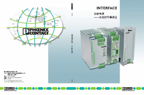
INTERFACE创新电源——系统的可靠保证菲尼克斯电气中国公司地址:南京市江宁开发区菲尼克斯路36号南京江宁236信箱电话:(025)52121888传真:(025)52121555/800 8289722邮编:211100h t t p: //e-mail: phoenix@ CN 11/12 INTERFACE 创新电源TNR 5768710/10.2011-01 Printed In China© PHOENIX CONTACT2011突破性技术——电源解决方案创新促进发展。
菲尼克斯电气的电源产品无疑印证了这一宗旨。
在对理想的电源探索中,我们洞悉市场,与客户密切合作,坚持与执着,不断创造出卓越的新产品技术。
我们的目标是最大程度提高您的设备和系统的可用性。
QUINT电源提供最优产品功能,三个新产品系列在各自领域里树立了新的标杆。
新产品采用ACB技术的冗余模块ACB(自动电流平衡)技术可使您的冗余电源系统的使用寿命翻倍。
该技术确保一定范围内所有的电源平衡输出。
QUINT ORING冗余模块的ACB技术还可检测临界工作状态,并为您提供提前预警。
新产品采用IQ技术的不间断电源具有持续电池监控和智能管理功能的IQ技术可随时为您提供电池的充电状态、剩余工作时间和使用寿命等相关信息。
智能通信功能将预警您危险工况的出现。
这可减少维护工作量,提升系统可用性。
新产品采用SFB技术的DC/DC变换器SFB(选择性触发)技术可在一旦输出回路出现短路时,可靠地切断故障回路。
在短路情况下,将能提供6倍额定输出电流,维持12ms时间。
因此,SFB技术能够可靠地触发标准断路器。
您可快速地进行故障定位,并确保系统的重要设备继续工作。
——采用SFB技术为系统有效性提供最高保证新一代紧凑型QUINT电源,将最大程度地保证系统的有效性。
该电源采用SFB技术(选择性触发技术),能在12ms内输出6倍的额定电流,可靠快速地触发标准断路器脱扣。
DCX114TK-7-F资料
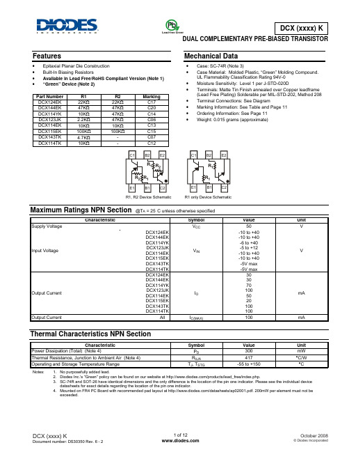
(Note 4) (Note 4)
Symbol PD RθJA
TJ, TSTG
Value 300 833
-55 to +150
Unit mW °C/W °C
Electrical Characteristics NPN Section @TA = 25°C unless otherwise specified
Part Number DCX124EK DCX144EK DCX114YK DCX123JK DCX114EK DCX115EK DCX143TK DCX114TK
R1 22KΩ 47KΩ 10KΩ 2.2KΩ 10KΩ 100KΩ 4.7KΩ 10KΩ
R2 22KΩ 47KΩ 47KΩ 47KΩ 10KΩ 100KΩ
Supply Voltage Input Voltage
Characteristic
Output Current Output Current
DCX124EK DCX144EK DCX114YK DCX123JK DCX114EK DCX115EK DCX143TK DCX114TK
DCX124EK DCX144EK DCX114YK DCX123JK DCX114EK DCX115EK DCX143TK DCX114TK
Characteristic
Input Voltage
DCX124EK DCX144EK DCX114YK DCX123JK DCX114EK DCX115EK
DCX124EK DCX144EK DCX114YK DCX123JK DCX114EK DCX115EK
Output Voltage
DCX124EK DCX144EK DCX114YK DCX123JK DCX114EK DCX115EK
914F安装手册
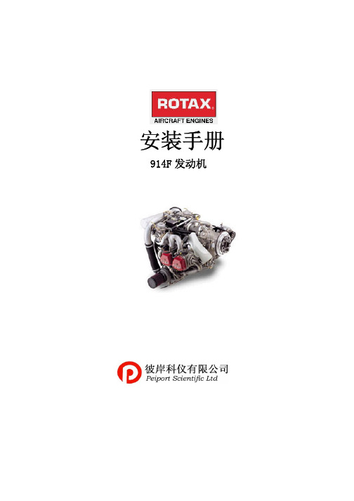
13.1)润滑系统介绍.............................................. 27 13.2)操作极限 ................................................. 28 13.3)滑油管和排放管的要求..................................... 28 13.4)连接尺寸和位置........................................... 29 13.4.1)滑油回路(发动机........................................ 29 13.4.2)滑油回路(涡轮增压).................................... 30 13.4.3)滑油箱 ................................................. 30 13.5)滑油箱安装位置............................................ 31 13.6)滑油散热器安装位置........................................ 32 13.7)关于滑油散热器的一般提示.................................. 32 13.8)容积 ..................................................... 33 14)燃油系统..................................................... 34 14.1)系统介绍 ................................................. 34 14.2)操作极限 ................................................. 35 14.3)供油系统的要求 ........................................... 35 14.4)连接的尺寸、位置和安装指导 .............................. 36
菲尼克斯开关电源选型手册2014
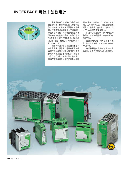
INTERFACE 电源|创新电源菲尼克斯电气的电源产品具有多种显著的优点,例如宽域的输入和多种国际认证确保了产品可在世界任何地方使用,在不稳定的电网中也能可靠输出,以及有压降补偿,同时将因电源故障而导致的停工时间降到最低。
三种产品系列覆盖了所有的应用领域:通用的QUINT电源,超薄的MINI电源和扁平的STEP电源。
优质的电源对复杂系统的功能是否可靠具有决定性作用。
菲尼克斯电气的电源产品依靠宽域的输入范围可以简单的与各种电压等级输电网相连,这就是为什么菲尼克斯电气的电源产品可在全世界范围可靠应用。
该产品有多种国际认证,包括CB图表,GL认证和IT应用的UL60950认证。
内置的大容量电容器为产品提供了高可靠性,保证了超过20ms的满负荷缓冲输出。
即使存在静态压降,或供电电压传输故障,或一相故障时,所有电源仍能可靠工作。
当负载启动时,如产生高电涌电流,则会造成压降,这时可由功率裕度进行补偿。
有监视报警功能诊断不允许的操作状态,以保证您系统的最大利用率。
标准尺寸为45-90mm的导轨安装插座,可方便的与成套件,维修单元和其它电气设备连接。
请参见2005年英文样本第432页灵活的安装附件,例如安装在S7导轨上的适配器或AC/DC电涌保护。
第166页保险丝模块,用于灯类的负载或变压器,防止电流过载请参见2005年英文样本第433页QUINT EX和根据EN50021设计的保护类型“n”冗余模块QUINTDIODE适用于防爆2区的场合。
第154-155页功能强大的QUINT POWER电源应用于通用控制柜,功率高达1000W,且有宽域输入范围。
第148-153页即使供电电压故障,电源仍可通过不中断电源QUINT BUFFER和QUINT DC-UPS确保系统安全操作。
第156-157页小巧超薄的电源MINI极大的节约了空间,最大功率可达100W。
第158-163页ASI QUINT电源为所有的AS-I系统供电。
dc dc电源模块手册说明书

DC/DC电源模块手册电源解决专家PowerGood ,为电源模块而诞生的专家PowerGood 之工业应用电源模块,兼具应用范围广及规格多样化特色,可应用于各种工业化设备与系统之中,功率从1W-600W ,输入电压范围涵盖9-700Vin ,符合多国安规认证及EMC 认证,除了提供电源模块以外、更提供弹性的模组化电源(PSU),提供快速性客制化服务,紧贴着应用市场的脉动。
PowerGood 不断推陈出新,提供客户最适切的产品,成为工业设备应用领域的领航者。
航天应用电源模块 医疗应用电源模块医疗行业所需求的电源模块,倾向于小型化及专业可靠。
为了因应于医疗设备及加强型隔离系统之严苛应用,PowerGood 所提供应用于医疗用之电源模块,为BF 等级设计,并且增强绝缘4k Vac ,低泄漏电流 100uA 。
适合应用于医疗机械设备之中,包含呼吸器、分析仪等各类设备。
并且随着新型医疗设备不断涌现,PowerGood 将因应市场需求,设计出更多符合需求之医疗应用电源模块。
PowerGood 创立于1989年,至今已经三十余年,提供客户最优异的品质、专利的拓扑电路、稳定的交期、专业的服务,成为客户最强大的事业后盾及伙伴。
PowerGood 产品线完整,从AC/DC 到DC/DC 电源转换器,提供标准品来满足客户需求,并与终端使用者合作,研发客制化产品,解决客户痛点,成为客户最大的后盾。
工业应用电源模块轨道应用电源模块轨道交通建设已经进入快速发展阶段,并且在AC/DC 及DC/DC 电源模块中提出了更严苛设计及挑战需求,PowerGood 了解轨道应用之环境严峻,因此产品皆符合轨道产业需求的高可靠、高耐用的特性,可应用于轨道之中的牵引设备、监控设备、通讯设备、驾驶设备...等系统之中。
PowerGood 的轨道系列产品工作壳温宽、隔离耐压高,并通过EN50155认证及EN45545-2防火保护认证,是轨道交通应用的最佳解决方案。
914F规格书

产品特性◆ 体积小,可供高密度PC 板安装◆ 使用的塑料材料耐高温和各种化学溶液◆ 切换电流能力可达 16A~20A◆ 两组转换可达5A~8A触点参数常开1组1A 、常开2组2A 、转换1组1C 、转换2组2C 银氧化镉 银氧化锡30VDC 250VAC 最大切换电流:20A 20A≤100m Ω电气10 5机械10 7线圈参数(20℃)4.04.87.29.619.238.4触点形式触点材料触点形式1A、1C 1A、1C 2A、2C 阻性480W 4000VA300W 2500VA 150W 1250VA 感性240W 2000VA150W 1875VA 90W 500VA最大切换电压最大切换电流接触电阻或压降寿命5 6.50.2547/3667.80.3068/50911.70.45155/1151215.60.60270/2002431.2 1.201100/8204862.42.404400/3300(第1页,共3页)吸合电压(VDC)线圈功率(w)0.54/0.72线圈电阻R(1±10%)Ω5A/250VAC,30VDC 2A/250VAC,3A/30VDC8A/250VAC,30VDC7.5A/250VAC 5A/30VDC16A/250VAC,30VDC 1A:20A/125VAC 10A/250VAC,30VDC 动作时间(ms)释放时间(ms)155释放电压(VDC)最大线圈电压(VDC)触点负载(阻性)阻性最大切换功率感性线圈额定电压(VDC)性能参数IEC255-5中第7条IEC 255-5中第6条IEC 255-5中第6条IEC 68-2-27 试验Ea订货标记示例914F SL 2C1、 产品型号: 914F3、 密封型4、 触点形式:1C:转换1组,1A:常开1组,2C:转换2组,2A:常开2组绝缘电阻 最小100M Ω(500VDC)介质耐压断开触点间 50Hz 1200V 触点与线圈间 50Hz 5000V 耐冲击 100m/s 2 11ms抗振性 10Hz~500Hz 双振幅1.5mm 引出端强度 10N可焊性 (230±2)℃ ,(10±0.5)s环境温度 0.54W:﹣30℃~70℃; 0.72W:﹣30℃~55℃ 85%(at 40°) 13g24VDC (第2页,共3页)相对湿度重 量2、 线圈电压:DC:5V,6V,9V,12V,24V,48V外形尺寸单位:mmmm inch 0.160.0060.30.0120.40.0160.50.0210.0391.30.0512.20.087外形尺寸 安装尺寸(底试图)3.50.13840.1575.080.27.50.29512.60.496200.78720.30.79920.60.811291.142注.1.)尺寸是以毫米计算.2.)给出的等量英寸尺寸值仅供参考参考数据接线图(底视图)(第3页,共3页)。
YHWKGS100W 四分之一DC DC 说明书

YHWK GS100W 四分之一DC/DC 说明书产品特点◆超宽输入电压范围(4:1)◆效率高达 94%◆隔离电压 2250VDC◆输入欠压保护,输出短路、过流、过压、过温保护◆工作温度范围:-40℃to+85℃◆金属五面屏蔽封装◆1/ 4 砖国际标准引脚方式100W ,宽电压输入,隔离稳压单路 DC/ DC 模块电源传导骚扰抗扰度IEC/EN61000-4-6, EN50121-3-2 10 Vr.m.sperf. Criteria A产品特性曲线YHWK GS100-48S24温度降额曲线(Vin=24V)YHWK GS 100-48S24Z 温度降额曲线(Vin=24V)环境温度(℃)环境温度(℃)YHWK GS100-48S24S 温度降额曲线(Vin=24V)注意事项:1)产品应用热设计需参考推荐的PCB 布局及推荐的散热结构环境温度(℃)注意事项:1)当不使用远端补偿时,确保+Vo 与 sense +,-Vo 与 sense -短接;2)+Vo 与 sense +,-Vo 与 sense -之间的连线尽可能短,并靠近端子。
避免形成一个较大的回路面积,当噪声进入这个回路后,可能造成模块的不稳 定。
2.当使用远端补偿时:尽可能使用双绞线注意事项:1.如果使用远端补偿的引线比较长时,可能导致输出电压不稳定,如果必须使用较长的远端补偿引线时请联系我司技术人员。
2.如果使用远端补偿,请使用双绞线或者屏蔽线,并使引线尽可能短。
3.在电源模块和负载之间请使用宽 PCB 引线或粗线,并保持线路电压降应低于 0.3V 。
确保电源模块的输出电压保持在指定的范围内。
4.引线的阻抗可能造成输出电压振荡或者较大纹波,使用之前请做好足够的评估。
Loa d+Vosense +Trim sense --Vo+CLoa d+Vo sense+ Trim sense--Vo+ C连接线尽可能短Sense 的使用以及注意事项亿鸿维克(1)产品测试及应用时,请按照(图 1)推荐的测试电路进行;至少保障外接一个电解电容 Cin (≥ 220µF ),用于抑制输入端可能产生的浪涌电压。
F-1414 U 变量滤波器(HP模型8445B)维修部件和特殊工具清单说明书

mal supply channels.
NOTE
Cannibalization or salvage may be used as a source of supply for any items source coded above except those coded XA and aircraft support items as restricted by AR 700-42.
(INCLUDING DEPOT MAINTENANCE REPAIR PARTS AND SPECIAL TOOLS) FOR
FILTER, VARIABLE F-1414/U (HP MODEL 8445B) (NSN 6625-00-253-4833)
Current as of 6 August 1981
(a) The maintenance code entered in the third position will indicate the lowest maintenance level authorized to remove, replace, and use the support item. The maintenance code entered in the third position will indicate one of the following levels of maintenance:
(2) Maintenance code. Maintenance codes are assigned to indicate the levels of maintenance authorized to USE and REPAIR support items. The maintenance codes are entered in the third and fourth positions of the Uniform SMR Code format as follows:
JS1-12V-F 规格参数
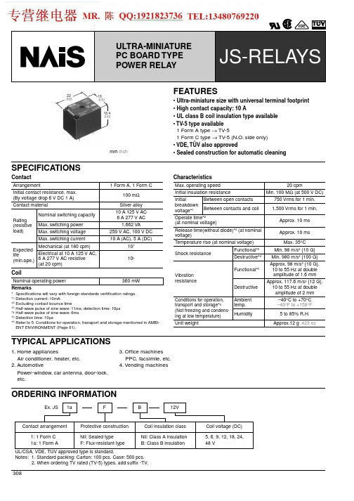
308mm inch16.4.64616.63022.866FEATURES• Ultra-miniature size with universal terminal footprint • High contact capacity: 10 A• UL class B coil insulation type available • TV-5 type available 1 Form A type → TV-51 Form C type → TV-5 (N.O. side only) • VDE, TÜV also approved• Sealed construction for automatic cleaningSPECIFICATIONSContactCoilCharacteristicsArrangement1 Form A, 1 Form CInitial contact resistance, max.(By voltage drop 6 V DC 1 A)100 m Ω Contact materialSilver alloy Rating (resistive load)Nominal switching capacity10 A 125 V AC 6 A 277 V AC Max. switching power 1,662 VAMax. switching voltage 250 V AC, 100 V DC Max. switching current 10 A (AC), 5 A (DC)Expectedlife(min.ope.)Mechanical (at 180 cpm)10 7Electrical at 10 A 125 V AC,6 A 277 V AC resistive(at 20 cpm)10 5Nominal operating power 360 mWMax. operating speed20 cpmInitial insulation resistance Min. 100 M Ω (at 500 V DC)Initial breakdownvoltage* 1Between open contacts 750 Vrms for 1 min.Between contacts and coil 1,500 Vrms for 1 min.Operate time* 2(at nominal voltage)Approx. 10 ms Release time(without diode)* 2 (at nominal voltage)Approx. 10 ms Temperature rise (at nominal voltage)Max. 35 ° C Shock resistanceFunctional* 3Min. 98 m/s 2 {10 G}Destructive* 4Min. 980 m/s 2 {100 G}Vibration resistanceFunctional* 5Approx. 98 m/s 2 {10 G},10 to 55 Hz at double amplitude of 1.6 mm DestructiveApprox. 117.6 m/s 2 {12 G},10 to 55 Hz at double amplitude of 2 mm Conditions for operation,transport and storage* 6 (Not freezing and condens-ing at low temperature)Ambient temp.–40 ° C to +70 ° C –40 ° F to +158 ° FHumidity 5 to 85% R.H.Unit weightApprox.12 g .423 ozRemarks*Specifications will vary with foreign standards certification ratings.* 1 Detection current: 10mA* 2 Excluding contact bounce time* 3 Half-wave pulse of sine wave: 11ms; detection time: 10 µ s * 4 Half-wave pulse of sine wave: 6ms * 5 Detection time: 10 µ s* 6 Refer to 5. Conditions for operation, transport and storage mentioned in AMBI-ENT ENVIRONMENT (Page 61).TYPICAL APPLICATIONS1. Home appliancesAir conditioner, heater, etc.2. AutomotivePower-window, car antenna, door-lock, etc.3. Office machines PPC, facsimile, etc.4. Vending machinesORDERING INFORMATIONJS309COIL DATAPart No.Nominalvoltage,V DC Pick-up voltage, V DC (max.)(at 20° C 68 ° F )Drop-out voltage, V DC (min.)(at 20 ° C 68 ° F )Coil resistance, Ω ( ± 10%)(at 20 ° C 68 ° F ) Nominal operating current, mA ( ± 10%)(at 20 ° C 68 ° F )Nominal operating power, mW (at 20 ° C 68 ° F )Max.allowablevoltage (at 60 ° C 140 ° F )Sealed type Flux-resistant type 1 Form A 1 Form C 1 Form A 1 Form C JS1a-5V JS1-5V JS1aF-5V JS1F-5V 5 3.50.569.472360130%V ofnominal voltage JS1a-6V JS1-6V JS1aF-6V JS1F-6V 6 4.20.610060JS1a-9V JS1-9V JS1aF-9V JS1F-9V 9 6.30.922540JS1a-12V JS1-12V JS1aF-12VJS1F-12V 128.4 1.240030JS1a-18V JS1-18VJS1aF-18V JS1F-18V 1812.6 1.890020JS1a-24V JS1-24V JS1aF-24V JS1F-24V 2416.8 2.41,60015JS1a-48VJS1-48VJS1aF-48VJS1F-48V 4833.64.86,4007.5DIMENSIONSmm inchNote: T erminal No. 4 is only for1 Form C typeGeneral tolerance: ± 0.3 ±.012Schematic (Bottom view)1a1cPC board pattern (Copper-side view)1a1cT olerance: ± 0.1 ± .004REFERENCE DATA1. Maximum value for switching capacity2. Operate/release timeSample: 25 pcs., JS1-12V3. Life curveAmbient temperature: Room temperatureJS4-(1). Coil temperature riseSample: 5 pcs., JS1-12VMeasured portion: Inside the coil Contact current: 5 A4-(2). Coil temperature riseSample: 5 pcs., JS1-12VMeasured portion: Inside the coil Contact current: 10 A5. Ambient temperature characteristicsSample: 6 pcs., JS1-12VFor Cautions for Use, see Relay Technical Information (Page 48 to 76).。
- 1、下载文档前请自行甄别文档内容的完整性,平台不提供额外的编辑、内容补充、找答案等附加服务。
- 2、"仅部分预览"的文档,不可在线预览部分如存在完整性等问题,可反馈申请退款(可完整预览的文档不适用该条件!)。
- 3、如文档侵犯您的权益,请联系客服反馈,我们会尽快为您处理(人工客服工作时间:9:00-18:30)。
R1, R2 Types
Input Voltage
Characteristic
Output Voltage Input Current Output Current DC Current Gain
DCX122LH DCX142JH DCX122LH DCX142JH
DCX122LH DCX142JH
DCX122TH DCX142TH
DCX122TH DCX142TH
DCX122TH DCX142TH
Symbol BVCBO BVCEO BVEBO
ICBO IEBO VCE(sat) hFE
Min
Typ Max Unit
Test Condition
50
⎯
⎯
V IC = 50μA
40
⎯
⎯
V IC = 1mA
leadframe. Solderable per MIL-STD-202, Method 208 • Terminal Connections: See Diagram • Weight: 0.005 grams (approximate)
A
CXXYM B C
D G
K H
M L
SOT-563
Dim Min Max Typ
IO(off) Gl
⎯
⎯ -0.5 μA VCC = -50V, VI = 0V
56 56
⎯
⎯ ⎯ VO = -5V, IO = -10mA
Gain-Bandwidth Product*
fT
⎯
200 ⎯ MHz VCE = -10V, IE = -5mA, f = 100MHz
* Transistor - For Reference OnБайду номын сангаасy
DCX122TH DCX142TH
VCE(sat) hFE
⎯
⎯ -0.3 V IC = -5mA, IB = -0.25mA
-2.0 -2.0
V VO = -0.3V, IO = -20mA VO = -0.3V, IO = -20mA
⎯
⎯ -0.3V V IO/Il = -5mA/-0.25mA
⎯
⎯
-28 -13
mA VI = -5V
Output Current DC Current Gain
DCX122LH DCX142JH
DDCX122LH DDCX142JH
Symbol Vl(off) Vl(on) VO(on) Il IO(off) Gl
Min Typ Max Unit
Test Condition
0.3 0.3
⎯
⎯
V VCC = 5V, IO = 100μA
⎯
⎯
2.0 2.0
V VO = 0.3V, IO = 20mA VO = 0.3V, IO = 20mA
DCX122LH DCX142JH DCX122TH DCX142TH
All
(Note 1, 2)
(Note 1)
Symbol VCC VIN
VEBO (MAX) IC Pd
RθJA Tj, TSTG
Value 50
-5 to +6 -5 to +6
5
100 150 833 -55 to +150
Unit V V
* Transistor - For Reference Only
Electrical Characteristics NPN Section @TA = 25°C unless otherwise specified
R1-Only
Characteristic
Collector-Base Breakdown Voltage
Maximum Ratings NPN Section
@TA = 25°C unless otherwise specified
Supply Voltage Input Voltage
Input Voltage
Characteristic
Output Current Power Dissipation Thermal Resistance, Junction to Ambient Air Operating and Storage Temperature Range
Characteristic
DCX122LH DCX142JH
DCX122TH DCX142TH
Symbol VCC VIN
VEBO (MAX)
Output Current
All
IC
Power Dissipation
(Note 1, 2)
Pd
Thermal Resistance, Junction to Ambient Air
A 0.15 0.30 0.25
B 1.10 1.25 1.20
C 1.55 1.70 1.60
D
0.50
G 0.90 1.10 1.00
H 1.50 1.70 1.60
K 0.56 0.60 0.60
L 0.15 0.25 0.20
M 0.10 0.18 0.11
All Dimensions in mm
DCX122TH DCX142TH
BVCEO BVEBO
ICBO IEBO
-40
⎯
⎯
V IC = -1mA
-5
⎯
⎯
V
IE = -50μA IE = -50μA
⎯
⎯
-0.5 μA VCB = -50V
⎯ ⎯
⎯
-0.5 -0.5
μA VEB = -4V
Collector-Emitter Saturation Voltage DC Current Transfer Ratio
⎯
⎯ 0.3V V IO/Il = 5mA/0.25mA
⎯
⎯
28 13
mA VI = 5V
⎯
⎯ 0.5 μA VCC = 50V, VI = 0V
56 56
⎯
⎯ ⎯ VO = 5V, IO = 10mA
Gain-Bandwidth Product*
fT
⎯
200 ⎯ MHz VCE = 10V, IE = 5mA, f = 100MHz
Collector-Emitter Breakdown Voltage Emitter-Base Breakdown Voltage
Collector Cutoff Current Emitter Cutoff Current Collector-Emitter Saturation Voltage DC Current Transfer Ratio
DCX122LH DCX142JH DCX122LH DCX142JH
DCX122LH DCX142JH
Symbol Vl(off) Vl(on) VO(on) Il
Min Typ Max Unit
Test Condition
-0.3 -0.3
⎯
⎯
V VCC = -5V, IO = -100μA
⎯
⎯
(Note 1)
RθJA
Operating and Storage Temperature Range
Tj, TSTG
Value -50
+5 to -6 +5 to -6
-5
-100 150 833 -55 to +150
Unit V V
V mA mW °C/W °C
Electrical Characteristics NPN Section @TA = 25°C unless otherwise specified
BVCBO
-50
⎯
⎯
V IC = -50μA
Collector-Emitter Breakdown Voltage Emitter-Base Breakdown Voltage
Collector Cutoff Current Emitter Cutoff Current
DCX122TH DCX142TH
Mechanical Data
• Case: SOT-563 • Case Material: Molded Plastic. UL Flammability
Classification Rating 94V-0 • Moisture Sensitivity: Level 1 per J-STD-020C • Terminals: Finish - Matte Tin annealed over Alloy 42
fT
⎯
200
⎯ MHz VCE = 10V, IE = -5mA, f = 100MHz
* Transistor - For Reference Only
DS30429 Rev. 3 - 2
2 of 4
DCX (LO-R1) H
© Diodes Incorporated
元器件交易网
NEW PRODUCT
DCX (LO-R1) H
COMPLEMENTARY NPN/PNP PRE-BIASED SMALL SIGNAL DUAL SURFACE MOUNT TRANSISTOR
Features
• Epitaxial Planar Die Construction • Built-In Biasing Resistors • Lead Free By Design/RoHS Compliant (Note 3) • "Green" Device (Note 4 and 5)
