RMDVB1-15PS001K中文资料
施耐德LC1D

0.20 1.56
0.20 1.56
最小/最大 截面积
1/4 1/4 1/4 1/2.5 1/4 1/4
1/4 1/4 1/4 1/2.5 1/4 1/4
2.5
0.20 1.56
1/4 1/4 1/4 1/2.5 1/4 1/4
2.5
0.36 1.56
1/4 1/4 1/4 1/2.5 1.5/6 1.5/6
型号
LC1-D0901ppN
D2N 系列接触器
用于电动机控制 6 ~ 32A (AC3) 用于配电电路控制 25 ~ 40A (AC1) 控制电路: 交流
交流控制线圈 单个接触器
LC 1 - D
N
线圈类型 常闭触点数 常开触点数 额定电流
AC-3 类 50/60Hz 三相电动机的特性 额定功率值
额定工作
kV
符合标准
防护等级
防护处理 设备周围 环境温度
符合 VDE 0106
符合 IEC 68 贮存 运行 允许
电源连接 线圈连接
°C °C °C
最高工作海拔
无降容
m
安装方式
无降容
阻燃
抗冲击 (1) 1/2 正弦波 = 11ms 抗震 (1) 5…300Hz
符合 UL 94 符合 IEC 695-2-1 接触器打开 接触器闭合 接触器打开 接触器闭合
辅助
电流
瞬时接点
AC-3 AC-1
440V θ ≤ 40°C
基本型号与指示 控制电路电压的编号 (1) 固定
重量
220V 380V
660V
230V 400V 415V 440V 500V 690V
kW kW kW kW kW kW A
RMD-L 电机用户手册V1.2
RMD-L电机驱动控制协议V1.2免责声明感谢您购买光毓机电RMD-L系列电机驱动系统。
在使用之前,请仔细阅读本声明,一旦使用,即被视为对本声明全部内容的认可和接受。
请严格遵守手册、产品说明和相关的法律法规、政策、准则安装和使用该产品。
在使用产品过程中,用户承诺对自己的行为及因此而产生的所有后果负责。
因用户不当使用、安装、改装造成的任何损失,光毓机电将不承担法律责任。
光毓机电是光毓机电(上海)有限公司及其关联公司的商标。
本文出现的产品名称、品牌等,均为其所属公司的商标或注册商标。
本产品及手册为光毓机电版权所有。
未经许可,不得以任何形式复制翻印。
关于免责声明的最终解释权,归光毓机电所有。
简介RMD-L电机驱动系统采用32位高性能MCU、高带宽运放、低内阻扁平封装MOSFET,结合FOC控制技术,搭配特别设计的高性能无刷电机,专为高精度、高响应、大扭矩应用打造。
电机与驱动的一体化设计,方便用户系统整合。
驱动集成高精度绝对值编码器,配合成熟的闭环控制算法,大幅提高了位置、速度和力矩控制的精度和响应。
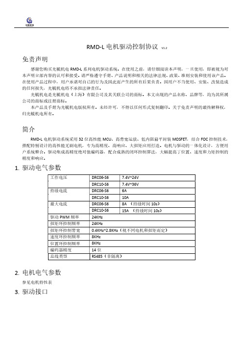
1.驱动电气参数2.电机电气参数参见电机特性表3.驱动接口4.总线特性总线接口芯片:MAX485波特率:9600, 19200, 57600, 115200(默认)数据位:8奇偶校验:无停止位:15.设定上位机连接电机驱动和上位机之间可以通过USB转RS485模块连接。
电机驱动出厂时默认波特率为115200,默认ID由拨码开关设定,一般为1,因此,上位机连接前的设置如下(其中COM根据实际情况选择),点击CONNECT按钮后,连接设备。
基础设定,在Setting页面中,点击Read按钮读取电机信息拨码开关与ID对应关系如下表:Driver BaudrateShutdown Time:设置电机的关闭时间。
在该时间内没有收到控制命令,电机会关闭;设置为0时,电机始终不会关闭。
Angle:角度环控制参数。
Kp和Ki修改角度环的PI参数,Max Angle用于限制电机的最大转动角度,例如设置为3600时,电机的最大转动角度为±3600°,即正反10圈。
新维AMDM-O01-100型电动机保护器使用说明书
AMDM-□/O011系列电动机保护器使用说明 产品概述主要特点:单片机为核心,数字设定,数字显示,保护功能完备、保护性能可靠,零序电流检测。
保护功能:缺相、短路、接地、堵转、过载、电流不平衡、零序。
适用范围:额定电压不高于1140V,频率为50Hz或60Hz的三相交流电动机。
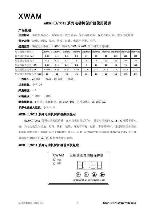
电动机保护器型号 AMDM-0.5 AMDM-1 AMDM-2AMDM-5AMDM-10AMDM-20AMDM-50 AMDM-100 AMDM-150AMDM-200最大设定电流(A) 0.55 1.1 2.3 5.5 11 23 55 110 165220最小设定电流(A) 0.1 0.2 0.4 1 2 4 10 20 30 40 电动机最大功率(KW) 0.22 0.4 1.1 2.2 4 11 22 45 75 110 电动机最小功率(KW) 0.055 0.11 0.22 0.55 1.1 2.2 5.5 11 18.5 22 电动机电源穿线孔Φ(mm)15 15 15 15 15 15 15 15 29 29 工作电压:AC 85V — 265V、DC 85V — 265V;功率消耗:小于 2W采集精度:1.0环境温度:- 20℃ — 50℃继电器触点:1常开、常闭触点,AC 250V/10A(阻性负载)、DC 30V/10A零序电流输入阻抗:小于 1 ΩAMDM-□/O011系列电动机保护器数据显示AMDM-□/O011系列电动机保护器,在电动机正常运行时,显示电动机的A、B、C相及零序电流;当电动机发生接地、短路、缺相、堵转、电流不平衡、过载、零序故障时,通过断开保护器内的继电器触点停止电动机运行(故障指示灯亮),同时显示故障代码指示电动机的故障类型,并且还显示发生故障时的A、B、C相及零序电流值。
AMDM-□/O011系列电动机保护器前面板组成LED 数码管显示区LED 数码管显示区有4位LED 数码管,显示电动机的三相及零序电流、故障代码及电动机保护器参数。
DLT德力通产品推介说明
DLTK系列乘客电梯产品推介说明一、公司简介湖南德力通电梯有限公司是一家集电梯的研发、制造、销售、安装和维保于一体的综合性企业。
公司座落于南北重要的交通枢纽湖南株洲,水陆交通通讯十分便利。
厂区占地2.5公顷,设有现代化车间(垂直电梯及自动扶梯生产流水线)和国际先进的专业检测、机械加工设备、研发中心等;拥有一批高素质的专业技术人才。
具备年产各类垂直电梯3500台、自动扶梯1000台的生产规模。
目前本厂产品已覆盖全国二十多个省市,并在长沙、广州、深圳、泉州、桂林、扬州、合肥、成都、兰州、潍坊等地设立了办事处及售后服务网点,负责本公司产品在当地的销售及售后服务工作。
德力通电梯有限公司与一些国际著名电梯配件厂商展开全面合作,专业从事高科技、数字化电梯的研究与开发,是世界电梯无机房、无齿轮高科技应用领域内的领先者。
让"用户满意"是德力通人的无上追求,质量与信誉是公司的一贯宗旨。
在生产质量控制与安装、服务过程中严格执行ISO9001-2000与ISO14000、OHSAS18000等相关国际标准管理体系,配备有专业的安装和服务队伍,设立了24小时服务的服务热线,建立起了辐射全国的服务网络和迅捷的备品备件供应体系,为客户提供全方位的服务与支持。
我们热情欢迎宾客用户惠顾、咨询、洽谈订货。
二、产品介绍DLTK系列乘客电梯,是湖南德力通电梯有限公司推出的最新一代高科技绿色环保产品,它具有高效节能、低噪声、无(齿轮箱)油污染、无电源电网污染等优点。
一、最先进的永磁同步拖动系统DLTK系列乘客电梯,采用国际上最先进的永磁同步变频调速拖动技术。
永磁同步电机不需要无功励磁电流,定子铜耗小,功率因素高,并具有低速性、快速性、硬机械特性、停车自闭等优点。
同时,永磁同步电机正常工作时不产生谐波干扰,对电源电网无污染。
二、平稳高效的无齿轮曳引系统DLTK系列乘客电梯,采用无齿轮曳引技术,没有齿轮啮合,彻底消除了齿轮机械传动的振动和噪声,使电梯运行更加平稳,噪声大为降低。
RMDVB1-15SS001P中文资料
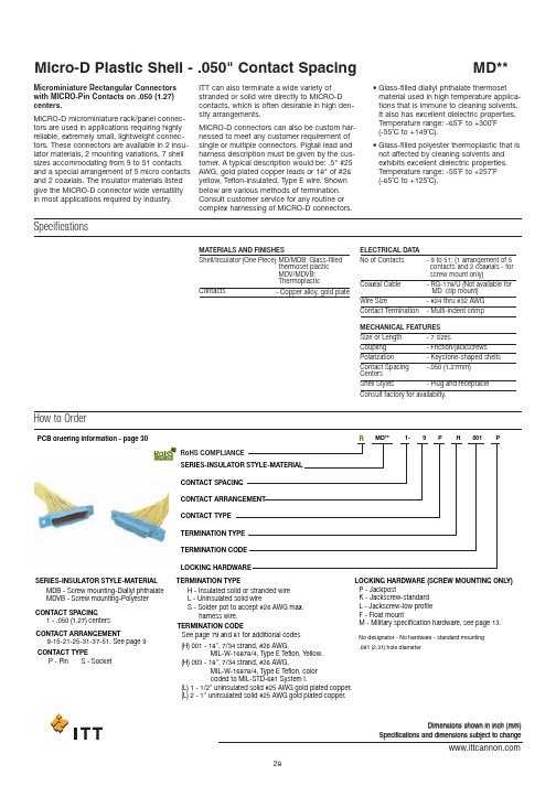
PCB ordering information - page 30SERIES-INSULATOR STYLE-MATERIAL SERIES-INSULATOR STYLE-MATERIALMDB - Screw mounting-Diallyl phthalate MDVB - Screw mounting-Polyester H -Insulated solid or stranded wire L -Uninsulated solid wireS -Solder pot to accept #26 AWG max.harness wire.No designator - No hardware - standard mounting .091 (2.31) hole diameterP -JackpostK -Jackscrew-standard L -Jackscrew-low profile F -Float mountM -Military specification hardware, see page 13.1-.050 (1.27) centers9-15-21-25-31-37-51. See page 9P -Pin S - SocketCONTACT SPACIN GCONTACT ARRAN G EMENTCONTACT TYPECONTACT SPACIN G CONTACT ARRAN G EMENT CONTACT TYPE TERMINATION TYPE TERMINATION TYPELOC K IN G H AR DW ARE (SCRE W MOUNTIN GONLY )TERMINATION CO D E LOC K IN G H AR DW AREM D** 1-9P H 001P(H) 001 - 18",7/34strand, #26 AWG, MIL-W-16878/4,T ype E T eflon, Y ellow.(H) 003 - 18",7/34strand, #26 AWG, MIL-W-16878/4,T ype E T eflon, color coded to MIL-S T D-681System I.(L) 1 - 1/2"uninsulated solid #25 AWG gold plated copper.(L) 2 - 1"uninsulated solid #25 AWG gold plated copper.TERMINATION CO D ERo H S COMPLIANCERSee page 79 and 81for additional codesDimensions shown in inch (mm)Specifications and dimensions subject to changeHow to OrderMicrominiature Rectangular Connectors with MICRO-Pin Contacts on .050 (1.27)centers.MICRO-D microminiature rack/panel connec-tors are used in applications requiring highly reliable, extremely small, lightweight connec-tors. These connectors are available in 2 insu-lator materials, 2 mounting variations, 7 shell sizes accommodating from 9 to 51 contacts and a special arrangement of 5 micro contacts and 2 coaxials. The insulator materials listed give the MICRO-D connector wide versatility in most applications required by industry.ITT can also terminate a wide variety of stranded or solid wire directly to MICRO-D contacts, which is often desirable in high den-sity arrangements.MICRO-D connectors can also be custom har-nessed to meet any customer requirement of single or multiple connectors. Pigtail lead and harness description must be given by the cus-tomer. A typical description would be: .5" #25AWG, gold plated copper leads or 18" of #26yellow, Teflon-insulated, Type E wire. Shown below are various methods of termination.Consult customer service for any routine or complex harnessing of MICRO-D connectors.•Glass-filled diallyl phthalate thermoset material used in high temperature applica-tions that is immune to cleaning solvents.It also has excellent dielectric properties.Temperature range: -65˚F to +300˚F (-55˚C to +149˚C).•Glass-filled polyester thermoplastic that is not affected by cleaning solvents and exhibits excellent dielectric properties.Temperature range: -55˚F to +257˚F (-65˚C to +125˚C).SpecificationsMATERIALS AND FINISHESShell/Insulator (One Piece)MD/MDB: Glass-filledthermoset plastic MDV/MDVB: Thermoplastic ELECTRICAL DATA MECHANICAL FEATURES No of ContactsSize or Length Coupling PolarizationContact Spacing Centers Shell StylesConsult factory for availabilty.Coaxial CableWire SizeContact Termination -9to 51: (1 arrangement of 5 contacts and 2 coaxials - for screw mount only)-7sizes-Friction/jackscrews-Keystone-shaped shells -.050 (1.27mm)-Plug and receptacle-RG-178/U (Not available for MD clip mount)-#24 thru #32 AWG -Multi-indent crimp-Copper alloy, gold plateContactsDimensions shown in inch (mm)Specifications and dimensions subject to changeStandard Wire Termination CodesCavity #1 black*The following termination codes are listed for your information. For additional codes please refer to Appendix on page 79 and 81. All wire lengths are minimum.#26 A WG per MIL-W-16878 Type E Teflon ,stranded.H arness Typ e (H)L ength 3(76.2)6(152.4)8(203.2)10(254.0)12(304.8)18 (457.2)20(508.0)24(609.6)30(762.0)36(914.4)48(1219.2)72(1828.8)120(3048.0)H020H019H026H029H028H001H038H009H010H011H013H017H042H027H016H034H025H002H003H023H004H005H006H048H046H041L61L 56L 57L 39L 58L 1L 14L2L 7L6L 16L 10.125(3.18).150 (3.81).190(4.83).250 (6.35).375(9.52).500 (12.70).750 (19.05)1.000 (25.40)1.500 (38.10)2.000 (50.80)2.500 (63.50)3.000 (76.20)All Y ell o w Co l o r Cod e d*T erminati o n Cod eL ength #25A WG G old P lated CopperS o li d U ninsulate d Typ e (L)With Screw Mounting Holes (Conforms to MIL-DTL-83513)MDB.110(2.79)MAX..154(3.91)(5.08)MAX.Solder PotSolder PotGlass-filled Diallyl Phthalate Plastic InsulatorMDVBGlass-filled Polyester Plastic InsulatorRPart Number by Shell Size Add lead type and length, see Part Number Explanation.Weight given is with 1/2", uninsulated solid #25 AWG gold plated copper pigtails.*****AMax.B Max.C Max.D Max.E Max.F ±.005Avg.Weight***±5% (oz.)±5% (gm.)MDB1-9S**MDB1-15P**MDB1-15S**MDB1-21P**MDB1-21S**MDB1-25P**MDB1-25S**MDB1-31P**MDB1-31S**MDB1-37P**MDB1-37S**MDB1-51P**MDB1-51S**MDVB1-9S**MDVB1-15p**MDVB1-15S**MDVB1-21P**MDVB1-21S**MDVB1-25P**MDVB1-25S**MDVB1-31P**MDVB1-31S**MDVB1-37P**MDVB1-37S**MDVB1-51P**MDVB1-51S**.788 (20.02).788 (20.02).938 (23.82)1.088 (27.64)1.088 (27.64)1.188 (30.18)1.188 (30.18)1.338 (33.98)1.338 (33.98)1.488 (37.80)1.488 (37.80)1.438 (36.52)1.438 (36.52).292 (7.42).380 (9.65).442 (11.23).592 (15.04).680 (17.27).692 (17.58).780 (19.81).842 (21.39).930 (23.62).992 (25.20)1.080 (27.43).942 (23.93)1.030 (26.16).408 (10.36).408 (10.36).588 (14.17).708 (17.98).708 (17.98).808 (20.56).808 (20.56).958 (24.33).958 (24.33)1.108 (28.14)1.108 (28.14)1.058 (26.87)1.058 (26.87).173 (4.39).173 (4.39).173 (4.39).173 (4.39).173 (4.39).173 (4.39).173 (4.39).173 (4.39).173 (4.39).173 (4.39).173 (4.39).220 (5.59).220 (5.59).218 (5.54).218 (5.54).218 (5.54).218 (5.54).218 (5.54).218 (5.54).218 (5.54).218 (5.54).218 (5.54).218 (5.54).218 (5.54).260 (6.60).260 (6.60).565 (14.35).565 (14.35).715 (18.16).865 (21.97).865 (21.97).965 (24.51).965 (24.51)1.115 (28.32)1.115 (38.32)1.265 (32.13)1.265 (32.13)1.215 (30.86)1.215 (30.86).026 (0.73).025 (0.70).038 (1.10).053 (1.50).050 (1.40).063 (1.80).056 (1.60).080 (2.30).073 (2.10).086 (2.45).076 (2.15).109 (3.10).093 (2.64)Dimensions shown in inch (mm)Specifications and dimensions subject to changeMD*B-PCB connectors use standard MD*B all plastic shells and are designed for use with flex circuitry, printed circuit and multi-layer boards. They are easily mounted and soldered and provide high density/high reliability in board-to-board and board-to-cable applica-tions. While being similar to the MDM-PCB connectors, the MD*B-PCB connectors are all plastic, extremely small, and lightweight yet rugged enough for use in the most demanding applications.MD*B-PCB connectors are available inseven shell sizes with 9 to 51 contacts in the popular 90°narrow profile PCB termination,with a variety of tail lengths for varying boardthickness.How to OrderSERIESCONTACT ARRANGEMENT CONTACT TYPE CTERMINATION TYPE THARDWAREHTERMINATION TAIL LENGTH TMODIFICATION CODES C(Consult Factory)MMD*B--37S CBR ** * *L39RoHS COMPLIANCE RJackpost mounting for use with locking hard-ware is also available.If the connectors shown in the catalog do not meet the requirements of your applica-tions, a special shape, size or layout using the basic all plastic shell can be made avail-able. For further technical and applications information, contact customer service.CONNECTOR SERIES MDVB, MDBCONNECTOR ARRANGEMENT9, 15, 21, 25, 31, 51CONTACT TYPES =Socket P =PinTERMINATION TYPECBR = 90°Narrow Profile PCB Terminations HARDWAREP =JackpostM7 = Jackposts, M635135-07No Letter = Less HardwareTERMINATION TAIL LENGTH CODESNONE –.109 (2.77) ±0.15 (0.38) Standard L61– .125 (3.18)L66– .150 (3.81)L57– .190 (4.83)L39–.250 (6.35)L58– .375 (9.52)Dimensions shown in inch (mm)Specifications and dimensions subject to changeCBR Series (90˚ Mounting Narrow Profile)TYP ..186 (4.72) PLUG 9-15-21-25 VIEW*FOR 31: 1.085 (27.56) MAX. FOR 37: 1.185 (30.10) MAX. FOR 51: 1.225 (31.12) MAX.I A. TYPPCB Termination Arrangements (Viewed from bottom of connector, on PCB solder side.)Indentification number shown for plug connector, use reverse order for socket connector..083.020.0209Contacts15 Contacts21 Contacts 25Contacts51 Contacts37 Contacts31 ContactsAll Termination Configurations .100 (2.54) x .100 (2.54) Grid Pattern, Offset .050 (1.27)*For jackpost locking add letter "P" or "M7".NOTE: Standard lead termination is #24 AWG, solid copper, solder or tin dipped.Part Number By Shell Size MD*B-9PCBR*MD*B-9SCBR*MD*B-15PCBR*MD*B-21PCBR*MD*B-21SCBR*MD*B-25PCBR*MD*B-25SCBR*MD*B-31PCBR*MD*B-31SCBR*MD*B-37PCBR*MD*B-37SCBR MD*B-51PCBR*MD*B-51SCBR.788 (20.01).938 (23.82)1.088 (27.63)1.088 (27.63)1.188 (30.17)1.188 (30.17)1.338 (33.98)1.338 (33.98)1.488 (37.79)1.488 (37.79)1.438 (36.52)1.438 (36.52).565 (14.35).715 (18.16).865 (21.97).865 (21.97).965 (24.51).965 (24.51)1.115 (28.32)1.115 (28.32)1.265 (32.13)1.265 (32.13)1.215 (30.86)1.215 (30.86).292 (7.42).525 (13.34).592 (15.04).675 (17.14).692 (17.58).775 (19.68).842 (21.39).925 (23.50).994 (25.25)1.075 (27.30).942 (23.93)1.026 (26.06).218 (5.54).218 (5.54).218 (5.54).218 (5.54).218 (5.54).218 (5.54).218 (5.54).218 (5.54).218 (5.54).218 (5.54).258 (6.55).258 (6.55).134 (3.40).218 (5.54).134 (3.40).218 (5.54).134 (3.40).218 (5.54).134 (3.40).218 (5.54).134 (3.40).218 (5.54).177 (4.50).258 (6.55).420 (10.67).420 (10.67).420 (10.67).420 (10.67).420 (10.67).420 (10.67).420 (10.67).420 (10.67).520 (13.21).520 (13.21).550 (13.97).550 (13.97).250 (6.35).250 (6.35).250 (6.35).250 (6.35).250 (6.35).250 (6.35).250 (6.35).250 (6.35).250 (6.35).250 (6.35).300 (7.62).300 (7.62).230 (5.84).130 (3.30).130 (3.30).130 (3.30).130 (3.30).130 (3.30).130 (3.30).130 (3.30).130 (3.30).130 (3.30).150 (3.81).150 (3.81)A Max.B±.005 (0.13)G±.010 (0.25)H±.010 (0.25)C Max.D Max.E Max.F Max.Dimensions shown in inch (mm)MDB Coaxial Series with Screw Mounting HolesMDB connectors with two coaxial and five MICRO-PIN TM /MICROSOCKET TM contacts. Crimp-type coaxial contacts accommodate RG-178/U cables. A plastic insertion/extraction tool is supplied with each connec-tor assembly having removable coaxial assembly.How to Order - MDB CoaxialSERIESMDB1-7C2****SHKSERIESMicro-D CoaxialNo Letter - Coaxial assemblyinstalled and nonremovable RO - coaxial assembly ordered serparatelyRA - Coaxial shipped assembled but uninstalled See Standard Wire TerminationConsult customer serviceNo letter - No hardware*Not available with removalbe coax cable type connectors RO and RA.standard mounting. 091 (2.31) hole diameter F -FloatK -Jackscrew (standard)L -Jackscrew (low profile)P -JackpostCode on page 29. Coaxial cable will beRG-178U unless otherwise specified; length will be same as wire modification.P -Pin S -Socket L -Uninsulated, solid wireH -Insulated, solid or stranded S -Solder pot*1-.050 (1.27) centers...................7 (2)SIGNAL CONTACT SPACING TOTAL CONTACT CAVITIES NUMBER OF COAXIALS SIGNAL CONTACT SPACING TOTAL CONTACT CAVITIES NUMBER OF COAXIALS COAXIAL TYPECOAXIAL TYPESIGNAL CONTACT TYPE SIGNAL CONTACT TYPESIGNAL CONTACT LEAD TYPE SIGNAL CONTACT LEAD TYPESIGNAL CONTACT LEAD LENGTH SIGNAL CONTACT LEAD LENGTH MODIFICATIONHARDWAREMODIFICATION HARDWARERoHS COMPLIANCE RHow to Order - Coaxial Cable AssembliesSERIESMDCCS** * *COAXIAL CABLE CONTACT TYPE CONTACT TYPE COAXIAL CABLE TYPECOAXIAL CABLE TYPE COAXIAL CABLE LENGTHCOAXIAL CABLE LENGTHSERIES MDP -Pin(used with socket side connection)S -Socket(used with pin type connection)See Standard Wire TerminationCodes on page 29. Coaxial cable will be RG-178U unless otherwise specified; length will be the same as wire modfication.1-RG178/UCOAXIAL CABLE CCRoHS COMPLIANCE RDimensions shown in inch (mm)Specifications and dimensions subject to changeDimension - MDB Coaxial SeriesPlugReceptacle(See page 9 for layouts)Part Numberby Shell SizeMDB1-7C2P*MDB1-7C2S*.510 (12.95).602 (15.29)* Add lead type and length, see Part Number Explanation.** Weight given is with 7 inch (177.80) insulated leads, #26 AWG silver plated copper pigtails and RG178/U coaxials..204 (5.18).185 (4.70).298 (7.57).279 (7.09).782 (19.86).782 (19.86).395 (10.03).375 (9.52).510 (12.95).540 (13.72).290 (8.30).273 (7.80)A Ma x.B Ma x.C Ma x.E Ma x.E 1Ma x.D +_.005 (0.13)Av g .W eight**(oz)+_5% (gm .)+_5%TWO MTG. HOLES RO AND RA COAXESRO AND RA COAXESMounting Hardware Views (Sizes 9-51)This hardware supplied unassembled.Screw Lock Assembly90˚ Angle Mounting BracketDescriptionScrew Lock Assembly Jackpost Kit322-9500-000 320-9505-000015-9516-000 .100 (2.54) .122 (3.10) .257(6.53).215(5.46)015-9516-000 Mounting Bracket, 90˚ Angle- MD*1for 9 thru 37 Shell Sizes MD*1for 51 Shell SizeNOTES: Screw lock assembly (322-9500-000) can be used for front front mounting. Jackpost kit(320-9505-000) consists of 2 assemblies, shipped unassembled.Part Number ±.005 (0.13)Max.*NOTE: Torque value is 4.0 in/lbs max. REF. ONLY_.003_0.08)FACEFACECONNECTOR HEX HEAD -Jackscrew - (L) Low ProfileJackscrew - (K) StandardThis hardware is factory installed.Shown here is a cutaway view of the float mount for the MD connector.The basic shell dimensions are the same for the float mount and the screw mounting hole configurations. View shown is for standard float mount front panel mounting. Reverse mounting is available on request.*NOTE: Torque values are as follows: Low Profile Jackscrew (L)-2.5 in/lbs Standard Jackscrew (K)-2.5 in/lbsDimensions shown in inch (mm)Specifications and dimensions subject to changeMounting Hardware to Military Specification (Sizes 9 - 51) PER MIL-DTL-83513/5This hardware supplied unassembled.Jackscrew - (L) Low profile *.062 (1.57)HEX. (REF.).092 (2.34) DIA.Allen headPlug and Receptacle Low and High Profile Slotted HeadJackpost AssemblyDescriptionSlotted Head Jackscrew Assy Low ProfileSlotted Head Jackscrew Assy High Profile Allen Head Jackscrew Assy Low Profile Allen Head Jackscrew Assy High Profile Jackpost Assy-05-06-02-03-07M5M6M2M3M7320-9508-025320-9508-027320-9508-026320-9508-028320-9505-033M83513/5Mode Code Part Number ThreadJackpost Bushing (For Rear Panel Mounting)MATING FACE.126 (3.20).125 (3.18)DIA.TYP .+.005 (0.13)3/32 (2.4)1/16 (1.6)3/64 (1.2)1/32 (0.8).092/.087 (2.34/2.21).061/.056 (2.34/1.42).047/.042 (1.19/1.07).030/.025 (0.76/0.64)320-9505-007320-9505-006320-9505-005320-9505-0049152125313751.379 ( 9.63).529 (13.44).679 (17.25).779 (19.79).929 (23.60)1.079 (27.41)1.029 (26.14).219 (5.56).219 (5.56).219 (5.56).219 (5.56).219 (5.56).219 (5.56).261 (6.63).565 (14.35).715 (18.16).865 (21.97).965 (24.51)1.115 (28.32)1.265 (32.13)1.215 (30.86)*2Jackposts, 2nuts, 2washers .Panel Thickness A Dim.Jackpost Kit Number*A+.004 (0.10)-.000 (0.00)Shell SizePlug and Receptacle DimensionsB +.004 (0.10)-.000 (0.00)C +_.005(0.13)NOTE: Torque value for jackpost 2.5 in /lbsPanel Mounting Dimensions.200 ±.005Plug and ReceptacleRear MountedPlug and Receptacle Front Mounted Plug Front Mounted Receptacle Rear Mounted.300 ±.005Dimensions shown in inch (mm)Specifications and dimensions subject to changePanel CutoutsFigure 1Front Mounting+.005 (0.13) R TYP -.000 (0.00)Figure 2Rear MountingFigure 3Edgeboard MountingNOTES:1. 2. 3. 123123123123123123123.409 (10.39).379 ( 9.63)-.559 (14.20).529 (13.44)-.709 (18.00).679 (17.25)-.809 (20.55).779 (19.79)-.959 (24.36).929 (23.60)-1.109 (28.17)1.079 (27.41)-1.059 (26.90)1.029 (26.14)-.172 (4.37).219 (5.56)-.172 (4.37).219 (5.56)-.172 (4.37).219 (5.56)-.172 (4.37).219 (5.56)-.172 (4.37).219 (5.56)-.172 (4.37).219 (5.56)-.215 (5.46).261 (6.63)-.570 (14.48).570 (14.48).570 (14.48).720 (18.29).720 (18.29).720 (18.29).870 (22.10).870 (22.10).870 (22.10).970 (24.64).970 (24.64).970 (24.64)1.120 (28.45)1.120 (28.45)1.120 (28.45)1.270 (32.26)1.270 (32.26)1.270 (32.26)1.220 (30.99)1.220 (30.99)1.220 (30.99).089 (2.26).089 (2.26).089 (2.26).089 (2.26).089 (2.26).089 (2.26).089 (2.26).089 (2.26).089 (2.26).089 (2.26).089 (2.26).089 (2.26).089 (2.26).089 (2.26).089 (2.26).089 (2.26).089 (2.26).089 (2.26).089 (2.26).089 (2.26).089 (2.26)9152125313751A+.004 (0.10)-.000 (0.00)B+.004 (0.10)-.000 (0.00)C+.005 (0.13)-.000 (0.00)D+.005 (0.13)-.000 (0.00)Cutout Figure Size Front mounting (figure 1) and rear mounting (figure 2) accommodates #2-56 screws.Front mounting is preferred. However, when rear mounting is necessary. use detail on previous page.Edgeboard mounting bracket (figure3) uses #2-56 screws. Dimension .450 ± .002 (11.43 ± 0.05) locates theMD receptacle flush with the end of the board.PlugMDGlass-filled Diallyl Phthalate Plastic InsulatorMDVGlass-filled Polyester Plastic InsulatorSolder PotSolder PotReceptacle.130(3.30)(5.33)(4.32).170(4.32)PCB ordering information - page 30SERIES-INSULATOR STYLE-MATERIAL SERIES-INSULATOR STYLE-MATERIALMD - Clip mounting -Diallyl phthalate MDV - Clip mounting-Polyester H-Insulated solid or stranded wire L -Uninsulated solid wireS -Solder pot to accept #26 AWG max.harness wire.No designator - No hardware - standard mounting .091 (2.31) hole diameterNot available in clip mounting.See page 79 and 81for additional codes.***(H) 001 - 18", 7/34strand ,#26 AWG ,MIL-W-16878/4, T ype E T eflon ,Y ellow.(H) 003 - 18", 7/34strand ,#26 AWG ,MIL-W-16878/4, T ype E T eflon ,colorcoded to MIL-S T D-681 System I.(L) 1 - 1/2"uninsulated solid #25AWG gold plated copper.(L) 2 - 1"uninsulated solid #25AWG gold plated copper.1-.050(1.27) centers9-15-21-25-31*-37-51.See page 7P -Pin S - Soc k etCONTACT SPACIN GCONTACT ARRAN G EMENTCONTACT TYPECONTACT SPACIN G CONTACT ARRAN G EMENT CONTACT TYPE TERMINATION TYPE TERMINATION TYPETERMINATION CO D E **TERMINATION CO D E LOC K IN G H AR DW AREM D1-9PH001PRo H S COMPLIANCERPart Number by Shell Size MD1-9P**MD1-9S**MD1-15P**MD1-15S**MD1-21P**MD1-21S**MD1-25P**MD1-25S**MD1-37P**MD1-37S**MD1-51P**MD1-51S**MDV1-9-P**MDV1-9S**MDV1-15P**MDV1-15S**MDV1-21P**MDV1-21S**MDV1-25P**MDV1-25S**MDV1-37P**MDV1-37S**MDV1-51P**MDV1-51S**A Max.B Max.C Max.D Max.E Max.Avg. Weight***±5% (oz.)/±5% (gm.).512 (13.00).512 (13.00).662 (16.81).662 (16.81).812 (20.62).812 (20.62).912 (23.16).912 (23.16)1.212 (30.78)1.212 (30.78)1.162 (29.51)1.162 (29.51).292 (7.42).376 (9.55).442 (11.23).526 (13.36).592 (15.04).676 (17.17).692 (17.58).776 (19.71).992 (25.20)1.076 (27.33).942 (23.93)1.026 (26.06).405 (10.29).405 (10.29).555 (14.10).555 (14.10).705 (17.91).705 (17.91).805 (20.45).805 (20.45)1.105 (28.07)1.105 (28.07)1.055 (26.80)1.055 (26.80).170 (4.32).170 (4.32).170 (4.32).170 (4.32).170 (4.32).170 (4.32).170 (4.32).170 (4.32).170 (4.32).170 (4.32).213 (5.41).213 (5.41).215 (5.46).215 (5.46).215 (5.46).215 (5.46).215 (5.46).215 (5.46).215 (5.46).215 (5.46).215 (5.46).215 (5.46).258 (6.55).258 (6.55).026 (0.73).026 (0.73).038 (1.10).035 (1.00).053 (1.50).050 (1.40).063 (1.80).056 (1.60).086 (2.45).076 (2.15).109 (3.10).093 (2.65)How to OrderWith Clip Mounting SlotsMicro-D Plastic Shell - .050" Contact Spacing MD**Panel Mounting HardwareClip MountingDescriptionDimensions (Clip Mounting Only)Coupling Retention Clip(see Figure 2)Mounting Screw Brackets(see Figures 1 and 3)PanelMounting KeyEdgeboard Mounted(see Figure 4)Plug and ReceptacleRear MountedPlug and ReceptacleFront Mounted Receptacle Rear MountedPart Number201-9100-000294-9100-000015-9100-000015-5009-000MD51428-1Panel Mounting KeyMounting Key and Coupling Clip AssemblyMounting Screw BracketEdgeboard Mounting BracketEdgeboard Mounting Bracket andCoupling Clip AssemblyMust be ordered separately; specify left and right hand for completeassembly.Must be ordered separately; assembly contains set of left and righthand types.******Illustrated is the recommended method of front mountingwith metal panel mounting keys. Panel mounting keys areavailable with or without coupling retention clips.For front mounting,place the rear of the connector thruthe panel cutout.With the mounting flange against thepanel,fully insert the panel mounting keys thru the slotsin the flange and thru the panel cutout.Retaining thekeys in this position, bend them outward against the rearof the panel.When mating a front mounted connectorwith an unmounted connector, a coupling retention clipassembly may be used to securely lock the two together.Mounting screw brackets are available and may be usedinstead of the panel mounting keys.Panel CutoutsFigure 1Figure 3Rear MountingFigure 4Edgeboard MountingFigure 2Front Mounting.).).MAX. (TYP.)A panel thickness of 1/8" 3.17mm) maximum is recommended for ease of tab bendingwhen a panel mounting key & clip assembly or edgeboard mounting brackets are used.Front mounting is preferred. However, when rear mounting is necessary, use figure 3 fordimensions.Figure 4 is for edge board mounting bracket or edgeboard clip assembly. The .184 +_ .0022.67 +_ 0.05) dimension locates the MD socket insulator flush with the end of the board.Screw brackets (015-9100-000) will accommodate #2-56 screws.Front mounting(Figure 1)and rear mounting(Figure 3)accommodate#2-56screws.1.2.3.4.5.ShellSize91521253751123412341234123412341234.408 (10.36).408 (10.36).378 ( 9.60).400 (10.16).588 (14.94).588 (14.94).528 (13.28).550 (13.97).738 (18.75).738 (18.75).678 (17.27).700 (17.78).838 (21.29).838 (21.29).778 (19.76).800 (20.32)1.138 (28.91)1.138 (28.91)1.078 (27.38)1.100 (27.94)1.088 (27.64)1.088 (27.64)1.028 (26.11)1.050 (26.67).172 (4.37).172 (4.37).217 (5.51).091 (2.31).172 (4.37).172 (4.37).217 (5.51).091 (2.31).172 (4.37).172 (4.37).217 (5.51).091 (2.31).172 (4.37).172 (4.37).217 (5.51).091 (2.31).172 (4.37).172 (4.37).217 (5.51).091 (2.31).215 (5.46).215 (5.46).260 (6.60).091 (2.31).650 (16.51)-.650 (16.51)-.795 (20.19)-.795 (20.19)-.945 (24.00)-.945 (24.00)-1.045 (26.54)-1.045 (26.54)-1.345 (34.16)-1.345 (34.16)-1.295 (32.89)-1.295 (32.89)-.089 (2.26)-.089 (2.26)-.089 (2.26)-.089 (2.26)-.089 (2.26)-.089 (2.26)-.089 (2.26)-.089 (2.26)-.089 (2.26)-.089 (2.26)-.089 (2.26)-.089 (2.26)-CutoutFigureA+.004 (0.10)-.000 (0.00)B+.004 (0.10)-.000 (0.00)C+.004 (0.10)-.000 (0.00)D+.005 (0.13)-.000 (0.00)38Dimensions shown in inch (mm)Specifications and dimensions subject to change 元器件交易网。
浙江华星电气科技有限公司2011年产品选型手册-1
注:由于受篇幅限制,所以不能针对公司所有产品一一进行选型指导,敬请谅解! 如需更多选型指导,请访问公司网站()或垂询公司销售部(0577-62781455)。
02 HUAXING ELECTRIC TECHNOLOGY
RPC □ □ □ □ - - □
无功功率补偿控制器型号命名规则
特点 详细请见第 13 页
· 128*64 点阵液晶显示屏 · 具有无功混合补偿功能 · 具有谐波分析功能 · 具有通讯功能 (2 通道 ) · 具有电能计量功能 · 具有历史数据记录功能 · 具有手动运行模式 · 配套后台分析软件 · 主要用配电监测
特点 详细请见第 13 页
· 240*120 点阵液晶显示屏 · 具有无功混合补偿功能 · 具有谐波分析功能 · 具有通讯功能 · 具有电能计量功能 · 具有历史数据记录功能 · 具有手动运行模式 · 配套后台分析软件 · 主要用配电监测
ंࢇց
ၚᆌ ้क़
?2t-বۅ
223nn!ġ223nn 24:nn!ġ24:nn 24:nn!ġ24:nn
24:nn!ġ24:nn
24:nn!ġ24:nn
?2t-ంସ
223nn!ġ223nn 223nn!ġ223nn
ļ31nt-ᆶᇸ
24:nn!ġ24:nn
ļ211nt-ᆶᇸ
本系列产品将在 2012 年全面停产
主要参数
电 源 380V 与电压信号共用 信号取样 3 相 4 线 最大回路 16 回路 最短延时 有源 0.1 秒 ; 节点 2 秒 有源输出 RPC3CD-BxTV2-12
RPC3CD-BxTV2-16 节点输出 RPC3CM-BxTV2-12
RPC3CM-BxTV2-16 开孔尺寸 112mm×112mm
Polaris-PJ1机器代码现场维修手册说明书

Polaris-PJ1机器代码:Y042/Y043/Y044/Y048/Y049/Y062/Y063/Y064/Y065/Y066现场维修手册2014年7月1日重要安全注意事项重要安全注意事项预防人身伤害1.拆卸或组装主机及外围设备的部件之前,确保已拔下主机的电源线插头。
2.墙壁插座应靠近机器,且易于使用。
3.主开关开启时,在外部盖板关闭或打开情况下若要执行任何调整或运行检查,双手应远离电气或机械驱动的部件。
•为防止火灾或爆炸,保持机器远离易燃液体、气体和气溶胶。
健康安全条件•本机使用了高压电源,将会产生臭氧气体。
高浓度臭氧对人体有害。
因此,必须将机器安装在通风良好的房间。
遵守电气安全标准•对本机及外围设备进行维修时,必须由受过此类机型全面培训的客户服务代表执行。
处理的安全和生态注意事项•根据当地法规处置更换的部件。
1目录重要安全注意事项 (1)重要安全注意事项 (1)处理的安全和生态注意事项 (1)1. 产品信息概述 (5)主单元 (5)控制面板 (6)连接端口 (7)规格 (9)一般规格 (9)兼容模式 (10)2. 安装安装要求 (13)环境/电源要求 (13)机器尺寸 (13)主机安装 (14)附件检查 (14)注意事项 (15)正确使用方法 (18)错误使用方法 (18)3. 更换和调整专用工具 (19)所需设备 (20)部件列表 (21)维修件列表 (21)可更换部件分级 (22)部件更换 (23)灯泡盖/灯泡组件 (23)顶盖板单元 (24)扬声器 (28)灯泡外壳 (28)LVPS (31)光学系统单元 (32)2吹气风扇 (39)底座/可调支脚 (40)更换部件后的必要动作 (42)4. 故障排除LED显示 (43)主要步骤 (45)光柱调整 (48)5. 测试&检验维修模式 (49)如何进入维修模式 (49)维修模式设置 (49)测试设备和条件 (54)所需的测试设备 (54)建议的测试条件 (54)校准 (55)风扇校准 (55)ADC校准 (56)重写灯泡时间 (58)色轮指数 (61)测试检验步骤 (62)检查事项 (62)OSD复位 (62)6. 更新固件更新 (63)所需设备 (63)固件更新步骤 (64)341. 产品信息概述主单元1.变焦杆2.控制面板3.连接端口54.通风口(入口)5.安全链开启6.扬声器7.遥控接收器8.可调支脚9.防盗锁孔(Kensington TM 锁)10.镜头盖11.透镜12.通风口(出口)13.对焦环控制面板1.梯形失真2.自动设置3.AV 静音4.四个方向选择键1. 产品信息65.温度指示器6.电源指示灯7.投影灯指示器8.电源9.菜单10.输入11.确定连接端口1.S-视频输入端子2.监视器输出端子3.计算机1输入端子4.计算机2输入端子5.AC 输入插口6.HDMI 输入端子7.维修端子8.PC 控制端子9.音频1输入端子10.音频输出端子11.音频2输入端子(用于视频和S-视频)12.视频输入端子概述71. 产品信息•接口以机型规格为准。
人民电器 水晶系列选型手册 RDM10系列塑料外壳式断路器(透明壳) 产品资料说明书

⽔晶系列选型⼿册CRYSTAL SERIES SELECTION MANUAL人民电器集团是人民控股集团全资公司,中国500强企业之一,始创于1986年。
人民电器集团以工业电器为核心产业,拥有浙江、上海、南昌、抚州、枣庄、合肥六大制造基地、35家全资子公司150家控股成员企业、1500多家加工协作企业和5000多家销售公司。
产品畅销全球125个国家和地区,广泛应用于浦东机场、京沪高铁、三峡水电、北京地铁、奥运场馆南水北调、青藏铁路、嫦娥探月工程、越南太安水电枢纽等国内外重大工程项目,位居世界机械企业500强前列。
2023年,经世界品牌实验室测评,品牌价值788.15亿。
一站式透明外壳断路器解决方案工地配电首选为全面支持全国复产复工建设需要,现针对透明壳产品,进行促销让利活动,详情敬请垂询当地授权代理商。
短路保护过载保护隔离保护漏电保护透明可视由于建筑工地用电环境的复杂性及特殊性,加上大多数的作业人员刚由农民转变而成,安全用电意识较差,以及用电设备的多样性、安全措施的不完备使建筑工地的电气事故增加,安全用电形式非常严峻。
常规产品在内部的触头熔焊,或粘连时,虽然开关处于分闸状态,实则依旧线路依旧导通,用户不易发现。
在停电时还会使停电线路带电。
会危及施工维护人员的安全。
透明断路器的好处是它在拉闸停电时你可以直观的看到断路器内部的断开点。
概述施工现场用电需求分类总配电箱、分配电箱、开关箱三级控制。
应用方案-总配电箱应用方案-分配电箱应用方案-开关箱三级控制RDM1400ARDM1 160ARDM1 160A6-8路RDM1 100A 3PRDB5T 63A 3P 水电RDB5T 63A 3P 消防RDB5T 40A 3P 备用RDB5T 63A 3P 备用RDM1系列塑料外壳式断路器RDM10系列塑料外壳式断路器DZ20系列塑料外壳式断路器DZ15系列塑料外壳式断路器RDL20系列漏电断路器DZ15LE系列漏电断路器RDM1L系列漏电断路器RDL18系列漏电断路器RDB5T-63、RDB5TLE-63系列小型断路器RDH5系列隔离开关HR6熔断器式隔离开关01 11 16 21 24 27 31 39 41 47 49Contents/01选型指南产品概述RDM1系列塑料外壳式断路器具有体积小、分断能力高、飞弧短、抗震动的特点, 是陆地及船舶使用的理想产品。
克罗韦尔 PowerFlex 755TM 非再生电源技术 数据表
技术数据PowerFlex 755TM 非再生电源系列号 20J主题第 ⻚简介3产品目录号说明3NRS 模块额定值说明6NRS 模块选型与系统额定值9NRS 系统配置11认证12环境技术参数12保护技术参数14电气技术参数14冲击事件15设计考量因素15控制变压器16近似功率损耗16降额指南18分⽀电路短路保护19机柜选件19符合 EN 61800-5-1 标准的污染等级19所需的机柜空气流量20便于操作和维修的最⼩安装间距21近似重量21附件252罗克⻙尔⾃动化出版物 750-TD103A-ZH-P - 2022年3 月罗克⻙尔⾃动化出版物 750-TD103A-ZH-P - 2022 年3 月3PowerFlex® 755TM 非再生电源 (NRS) 技术可提供精确的公共⺟线系统配置。
该技术融合了多项功能,可帮助优化系统,保持生产率。
PowerFlex 755TM 非再生电源具有如下一系列特性,可帮助⽤⼾最⼤程度提⾼生产率:•PowerFlex 755TM 变频器系统 — 精选一系列配置,可优化系统设计,并降低功耗。
NRS 系统具有设计灵活和安装成本低等优点。
•腐蚀性气体防护 (XT) — PowerFlex 755TM 产品目前均标配腐蚀性气体防护(XT)。
带 XT 的 NRS 产品将敷形涂覆与多项额外设计增强特性相结合,旨在提升在腐蚀性气体工况(例如轮胎和橡胶、废⽔处理、纸浆和纸张以及⾦属⾏业等)下的性能表现。
•NRS 模块推入、拉出式设计 — 使 NRS 系统易于安装和维修。
产品目录号说明本节介绍了基本 NRS 模块功率模块柜的产品目录号。
一个完整版 NRS 系统可以是单个功率模块柜,也可以是配备一个或多个接线柜的并联功率模块柜系统,如果采⽤了背靠背配置,还可以是两个直流电压平衡电源柜。
并联系统中的每个功率模块柜都有各⾃对应的产品目录号。
整个并联系统没有产品目录号。
产品目录号的第 1…7 位标识产品类型和电压等级。
[VIP专享]红外热释电处理芯片BISS0001介绍
![[VIP专享]红外热释电处理芯片BISS0001介绍](https://img.taocdn.com/s3/m/c34457d984868762caaed58a.png)
红外热释电处理芯片BISS0001介绍BISS0001是一款具有较高性能的传感信号处理集成电路,它配以热释电红外传感器和少量外接元器件构成被动式的热释电红外开关。
它能自动快速开启各类白炽灯、荧光灯、蜂鸣器、自动门、电风扇、烘干机和自动洗手池等装置,特别适用于企业、宾馆、商场、库房及家庭的过道、走廊等敏感区域,或用于安全区域的自动灯光、照明和报警系统。
特点 CMOS工艺 数模混合 具有独立的高输入阻抗运算放大器 内部的双向鉴幅器可有效抑制干扰 内设延迟时间定时器和封锁时间定时器 采用16脚DIP封装 工作原理 BISS0001是由运算放大器、电压比较器、状态控制器、延迟时间定时器以及封锁时间定时器等构成的数模混合专用集成电路。
以下图所示的不可重复触发工作方式下的波形,来说明其工作过程。
不可重复触发工作方式下的波形。
首先,根据实际需要,利用运算放大器OP1组成传感信号预处理电路,将信号放大。
然后耦合给运算放大器OP2,再进行第二级放大,同时将直流电位抬高为VM(≈0.5VDD)后,将输出信号V2送到由比较器COP1和COP2组成的双向鉴幅器,检出有效触发信号Vs。
由于VH≈0.7VDD、VL≈0.3VDD,所以,当VDD=5V时,可有效抑制±1V的噪声干扰,提高系统的可靠性。
COP3是一个条件比较器。
当输入电压VcVR时,COP3输出为高电平,进入延时周期。
当A端接“0”电平时,在Tx时间内任何V2的变化都被忽略,直至Tx时间结束,即所谓不可重复触发工作方式。
当Tx时间结束时,Vo下跳回低电平,同时启动封锁时间定时器而进入封锁周期Ti。
在Ti时间内,任何V2的变化都不能使Vo跳变为有效状态(高电平),可有效抑制负载切换过程中产生的各种干扰。
以下图所示的可重复触发工作方式下的波形,来说明其工作过程。
可重复触发工作方式下的波形在Vc=“0”、A=“0”期间,信号Vs不能触发Vo为有效状态。
德欣集团热保护压敏电阻产品规格说明书

SPD Series Specifications德欣集团深圳市德欣电器有限公司SPD全系列规格书产品名称:热保护压敏电阻型号规格: COV25D-COV60D(201K~162K)日期: 2019年6月30日本集团公司旗下总生产面积 60000 平米以上,主营产品压敏芯片及压敏电阻器,电压范围从15V--1800V,产品直径从3mm--80mm均能全系列生产,年产能压敏芯片12亿只以上,压敏电阻器成品8亿只以上,综合年产能20亿只以上,为国内压敏芯片,压敏电阻器产能最大生产商之一,其中(15V-82V)低压压敏芯片,产能,产量,市场占有率位居世界第一。
本公司旗下所生产的全系列产品均有完善的认证体系:具备CQC,UL,CSA,VDE,SGS等多国认证,产品畅销多个国家,全员推行并遵守ISO9001质量管理体系,ISO14001环境管理体系,OHSAS18001职业健康安全管理体系,拥有国家发明专利6项,实用新型专利7项,为高新技术企业。
华北生产基地:山东省德州市平原县经济开发区德欣电器高新科技产业园华南生产基地:惠州市惠阳区秋长将军路合美兴工业园西南生产基地:四川省南充市阆中市七里汉王祠路小微企业孵化园 3 号联系人:林茂发移动电话:136****5669固定电话:*************官方网站:SPD Series Specifications SPD 系列规格说明 Explanation of Part Numbers 型号说明:-Specifications 规格说明:□Varistor Voltage Range压敏电阻动作电压范围 200V~1600V(dc) □Peak Current For 8/20us Current Wave在8/20us电流波形最大通流量 20KA~70KA □Energy Range For 10/1000us Current Wave在10/1000us电流波形的能量范围 250J~2500J □Storage Temperature Range储存温度范围 -40℃~85℃℃ □Operation Ambient Temperature Range作业环境温度范围储存温度范围 -40℃~85℃ □Typical Response Time反应时间 〈25ns □Insulation Resistance绝缘电阻 ≧1000MΩApplications 应用领导域:▇ Protection Of Communication Against Lightning 通信电源防雷保护▇ Industrial Power Distributors 工业配电柜▇ Railway Highway and Air-signal 铁路、公路、航空信号系统▇ Building Power Distributors Input Against Lightning 大楼供电电源入端防雷COV D KC Common Code 产品类别代码DE xin COV Metal Oxide Varistor Surg e Absorber 德欣COV 金属氧化物压敏电阻器 25 32,.34 53 60ChipDiameter 芯片直径 Φ25mm Φ32mm S34mm Φ53mm Φ60mmChip .Shape芯片形状Varistor Voltage 压敏电阻动作电压例如Examples: 47 × 100 = 47 V 47 × 101 = 470 V 11 × 102 = 1100 V47471112Tolerance 误差 K .±10%L .±15% M .±20% OrCustomer Special Requirem entD-Disc 圆形B-Block 塑胶方S-Square 方形Enclosure 包封材质C:Epoxy 环氧树脂 E:Plastic...Case 注塑外壳Tab Style 引出端形状P Planet 平板型 L L Shape L 型 C Radial 圆型L•25D Specifiation*32D Specification(表一:基本尺寸表)(表二:厚度尺寸表) (图1:32D系列简图)SPD Series Specifications *40D Specification(表一:基本尺寸表)(表二:厚度尺寸表) (图1:40D系列简图)*53D Specification(表一:基本尺寸表)(表二:厚度尺寸表) (图1:53D系列简图)*34S Specification(表一:基本尺寸表)(表二:厚度尺寸表) (图1:34S系列简图)*34B (BLOCK VARISTOR) Specification注:未注明公差±0.5mm(图1:34B系列简图)*60B (BLOCK VARISTOR) Specification注:未注明公差±0.5mm(图1:60B系列简图)V-I Curve 电压电流特性曲线:第 21 页 SPD Series Specifications。
浙江华星电气科技有限公司2010年产品手册-1
特点 详细请见第29页
◆ 数码管显示屏 ◆ 只用于3相共补 ◆ 具有过压保护功能 ◆ 具有功率因数和无功
功 率2种 工 作 模 式 ◆ 具有手动运行模式 ◆ 价格经济,工作稳定可靠
主要参数
电 源 380V 信号取样 2相电压1相电流 最大回路 12 最短延时 节点1秒 节点输出 RPC5BM-12 开孔尺寸 162mm×102mm
S
RPC3F M C-18系列无功功率分相补偿控制器 --15
FS
RPC3 C M系列无功功率自动分相补偿控制器---20 RPC1FK-BC-12无功功率动态补偿控制器----22
F
RPC5 C M-B系列无功功率自动补偿控制器----24 RPCGFM-BC-6高压补偿控制器 ----------26 HXGK系列高压无功功率自动补偿控制器-----27 普通型无功功率自动补偿控制器 -----------29 PPM-06电网参数显示仪 ----------------32 PPM-90电网参数分析仪 ----------------33 干式铁芯串联电抗器 -------------------35 HX·XBY电力谐波抑制器 ---------------36 编码输出方式 ------------------------37 通讯附件----------------------------39 通讯软件----------------------------41
特点 详细请见第29页
◆ 数码管显示屏 ◆ 只用于3相共补 ◆ 具有过压保护功能 ◆ 具有功率因数和无功
功 率2种 工 作 模 式 ◆ 具有手动运行模式 ◆ 价格经济,工作稳定可靠
产品导读
快 RPC1FK-BC-12 速 补 偿 型 控 制 器
ZY_BKD-1W非稳压单输出隔离电源模块说明书
——————————————概述定压输入、非稳压单输出隔离电源模块效率高、体积小、可靠性高、耐冲击、隔离特性好,温度范围宽。
国际标准引脚方式,阻燃封装(UL94-V0),自然冷却,无需外加散热片,无需外加其他元器件可直接使用,并可直接焊接于PCB 板上。
适用于由开关电源或其他稳压源供电,对输出电压及纹波要求不高,小电流隔离和DC-DC 电压变换的场合,如大功率IGBT 驱动、纯数字电路、一般低频模拟电路、RS232、RS485、CAN-bus 隔离通讯系统等,电路结构为开环系统。
——————————————产品特性◆ 非稳压单输出; ◆ 效率高达84%; ◆ 1000VDC 隔离电压;◆ 外壳及灌封材料符合UL94-V0标准; ◆ 无需外加散热器;◆ 工作温度-40~+85℃;◆封装:DIP-28与国际、国内同类型产品PIN 对PIN 兼容; ◆ MTBF>100万小时;◆ 不适用于输入电压波动范围大于10%或对电压精度要求特别高的场合。
————————————产品应用◆ RS232、RS485/422、CAN-bus 等隔离通讯接口 ◆ 大功率IGBT 驱动◆ 纯数字电路、模拟前端隔离电路 ◆ 一般低频模拟电路 ◆ 运算放大器电源 ◆ ……—————————————订购信息广州致远电子股份有限公司型号 温度范围 封装ZY_BKD-1W-40℃—+85℃DIP———————————————————————————— 原理框图图 1 原理框图图1为模块内部原理框图,由一个高效率的双极型逆变器推动一个隔离变压器,在隔离变压器的次级得到一个电压,经肖特基二极管整流后输出直流电压。
其开关电源的工作方式使电源模块具有效率高、体积小、应用简单等特点。
修订历史版本日期原因Rev X1 2007-8-5 内部制定初稿Rev 1.0 2009-8-10 第一次发布销售与服务网络(一)广州致远电子股份有限公司地址:广州市天河区车陂路黄洲工业区3栋2楼邮编:510660传真:(020)38601859网址:新浪微博:ZLG-周立功(/ligongzhou)销售及技术支持:x86工控:销售电话:(020) 28267893 22644261 28267985 技术支持:(020) 28872451******************CAN-bus:销售电话:(020) 28872524 28872342 28872450 技术支持:(020) 22644381 22644382******************MiniARM及ARM工控:销售电话:(020) 22644261 28267985 28267893 技术支持:(020) 28872684 28872412**********************ZigBee及以太网:销售电话:(020) 28872524 28872342 28872450 技术支持:(020) 22644380 22644385***********************分析仪器:销售电话:(020) 28872453 28872569 技术支持:(020) 22644375**************串行通讯:销售电话:(020) 28872524 28872342 28872450 技术支持:(020) 28267800 22644385*************编程器:销售电话:(020) 28872453 28872569 技术支持:(020) 22644371**************无线通讯:销售电话:(020) 28872524 28872342 28872450 技术支持:(020) 22644386**********仿真器:销售电话:(020) 28872453 28872569 技术支持:(020) 22644360**************数据采集及iCAN:销售电话:(020) 28872524 28872342 28872450 技术支持:(020) 28267821***********楼宇自动化:销售电话:(020) 28872573技术支持:(020) 22644389 28267806***************************************电源产品:销售电话:(020)28267835 28267859技术支持:(020) 22644373 28267925************免费服务电话:400 888 4005销售与服务网络(二)广州周立功单片机科技有限公司地址:广州市天河北路689号光大银行大厦12楼F4邮编:510630传真:(020)38730925网址:电话:(020)38730916 38730917 38730972 38730976 38730977新浪微博:ZLG-周立功(/ligongzhou)广州专卖店地址:广州市天河区新赛格电子城203-204室电话:(020)87578634 87569917传真:(020)87578842 南京周立功地址:南京市珠江路280号珠江大厦1501室电话:(025) 68123901 68123902传真:(025) 68123900北京周立功地址:北京市海淀区知春路113号银网中心A座1207-1208室(中发电子市场斜对面)电话:(010)62536178 62536179 82628073传真:(010)82614433 重庆周立功地址:重庆市石桥铺科园一路二号大西洋国际大厦(赛格电子市场)2705室电话:(023)68796438 68796439传真:(023)68796439杭州周立功地址:杭州市天目山路217号江南电子大厦502室电话:(0571)89719480 89719481 8971948289719483 89719484 89719485传真:(0571)89719494 成都周立功地址:成都市一环路南二段1号数码科技大厦403室电话:(028)85439836 85437446传真:(028)85437896深圳周立功地址:深圳市福田区深南中路2072号电子大厦12楼电话:(0755)83781788(5线)传真:(0755)83793285 武汉周立功地址:武汉市洪山区广埠屯珞瑜路158号12128室(华中电脑数码市场)电话:(027)87168497 87168297 87168397传真:(027)87163755上海周立功地址:上海市北京东路668号科技京城东楼12E室电话:(021)53083452 53083453 53083496传真:(021)53083491西安办事处地址:西安市长安北路54号太平洋大厦1201室电话:(029)87881296 83063000 87881295传真:(029)87880865厦门办事处E-mail:***********************沈阳办事处E-mail:*************************目录1. 引脚信息 (1)2. 机械尺寸 (2)3. 电气参数 (3)3.1 ZY_BKD-1W特性参数 (3)4. 特征曲线图 (4)5. 电路连接 (5)5.1 ZY_BKD-1W系列电路连接 (5)6. 产品列表 (6)7. 声明 (7)1. 引脚信息●产品实物图图 1.1 ZY_BKD-1W实物图产品尺寸:长(L)*宽(W)*高(H),20*8.1*10mm。
200 315 济源科灵软起动说明书
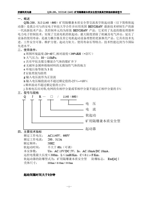
一、概述QJR-200、315/1140(660)矿用隔爆兼本质安全型交流真空软起动器(以下简称软起动器)是我公司与西安电子科技大学合作并应用美国BENSHAW 最新技术研制生产的新一代高新技术产品,其控制单元均为原装BENSHAW 产品,它采用了先进的微处理器和电力电子控制技术,实现了交流电机的软起动,最大限度消除了机械及电气冲击,延长了设备的使用寿命,是液力耦合器及其它电机起动设备理想的更新换代产品。
它具有技术先进、工件安全可靠、维护方便、起动力矩大、使用寿命长等特点,技术性能达到当今国际先进水平。
二、使用条件:a 周围环境温度-20~40℃,相对湿度≤96%RH (+25℃)b 大气压力:80~110kPa ;c 具有甲烷及煤尘爆混合气体的煤矿井下d 无破坏金属和绝缘材料的无腐蚀性气体的地方e 环境污染等级为3级f 安装类别为Ⅲ类g 输入电压波形为正弦波h 输入电压幅值波动不超过额定值的-25%--+10% i 频率波动不超过额定值的±2%j 各相电压应对称,电网的负相序分量或零相序分量不超过正相序分量的5% 三、型号与规格Q J R — □ / 1140(660)四、主要技术指标额定工作电压: AC1140V 、660V 额定工作电流: 200、315A 额定频率: 50HZ软起动时间: 不大于60s (可调)本安参数: Uo :AC 13V/DC 5V ;Io :AC 10mA/DC 10mA 。
远控电缆最大长度≤300m ,L ≤1mH/Km ,C ≤0.1μF/Km 。
软起动器的防爆型式为:矿用隔爆兼本质安全型 防爆标志: Exd[ib]Ⅰ 壳体尺寸: 800mm ×640mm ×940mm起动间隔时间大于5分钟电 压 电 流 软起动 矿用隔爆兼本质安全型 起动器介电强度按MT/T943—2005第4.4.2条进行选取参数如表1所示执行标准:GB3836-2000Q/JKL208-2011五、主要功能特点1、核心件全部采用美国BENSHAW公司生产的全套产品,微处理器、检测模块、保护模块,具有技术先进,功能齐全,性能稳定,抗干扰能力强,运行可靠等特点。
15K高清机芯系列维修手册

15K高清机芯系列维修手册—— HDP2908D青岛海信电器股份有限公司2008年8月一、机芯介绍机芯功能介绍在功能上可以实现模拟机芯上,可以输入高清信号、VGA信号,其中高清信号可以显示1080P/60,1080I/60,1080I/50,720P/60和逐行DVD信号(图像)。
VGA方式支持640*480/60 模式。
产品外观介绍HDP2908D为08系列外观,采用原TF2908D外观。
产品差异介绍目前此方案的在29寸普通机型TF2908D基础上增加高清、VGA信号输入功能,通原TF2908D外壳。
二、机芯概述HDP2908D机芯是采用东芝G2机芯+华亚公司的芯片HTV158单芯片的视频处理方案,东芝G2集成了小信号处理、CPU。
数字兼容板板号是RSAG7.820.1176。
主板是RSAG7.820.1180,场块采用三洋LA78041、电源块采用仙童FSCQ1265、伴音功放电路为AN17921。
视放板板号RSAG7.820.1200。
三、原理说明 电源部分1.电源框图+B + 129V 行包+33V 高频头+8V BD034 数字兼容板+13V 伴音功放+12V BD034 +8V 主芯片7805 +5V-1 CPU+27V 行推动300V高压 29 KV聚焦电压栅压视放电压 200V灯丝电压 6.3V图像信号处理部分机芯方框图信号流程小信号处理部分主要由主芯片N201(TMPA8879)、伴音功放N602 (AN7523/AN17823)及其外围电路组成。
电视信号输入到调谐器,经过高放、混频后输出的固定的中频信号(38MHz),经过预中放电路V101(2SC388A)、声表面滤波器Z101 (K3876)放大后输入到N201的Pin41、Pin42,经过PLL同步检波后,从N201进行内部进行亮度、色度处理后的Pin30、Pin31、Pin32输出R、G、B信号给视放电路;Pin28、Pin29输出音频信号,经N601(可选)音效处理后,再经N602功放进行放大输出到喇叭。
TCLERP项目ERP元件编码规则体系(可编辑)

TCL ERP项目ERP元件编码规则体系注: 此编码规则是在前编码系统的基础上, 对18类、22类、26类、27类、36类、37类、40类、45 类、47类、48类、50 类、51类属安全件的物料进行厂家区分后整理而成, 请注意查询。
ERP系统物料编码规则TCL元件编码规则体系标准实践标准编码体制范围:本标准建立编码体制以识别图纸、工程规格、以及根据所得的图纸、规格表示出限定的零件和材料。
目的:本标准编码体制为识别文件、图纸、说明书、零件及材料规定了一个统一的方法, 规定提供以下一些方法。
在工程标准方案中识别每种图纸、规格、标准、零件、材料。
将零件和材料分类以简化选择、获取、测试、检查及材料控制。
减少文件及零件种类、数量, 避免重复。
图纸及规格的编码:3.1所有在本标准范围内正式发行的图纸和规格, 用适合该种类型所指定的一个数字来识别3.2本标准编码体制采用顺序编码法。
3.3图纸和工程规格的鉴别数字由物品码的前缀加指定顺序的基础数字组成。
3.3.1物品码: 物品码为二个数字的前缀,以此识别一般产品分类。
3.3.2顺序基数:基数是一个5个字数字(在10000到99999之间), 以此对专用的图纸或规格给出唯一的识别, 但它没有分类编码的意思, 这数和物品名前缀之间用破折号分开。
3.4具有限定技术要求和制造资料的图纸(或规格)的零件(或)材料, 其识别数字应有和图纸、规格、相同的物品码和基数字,附加1个阿拉伯数字识别,并有3 个阿拉伯数字的后缀。
4 . 零件和材料的编码::4.1 结构所有零件、组件、部件及材料被指定为三个元素组成的一条鉴别数字: 一个物品码, 一个基数本体和一个后缀。
4.1.1 物品码: 物品码是识别一般产品分类的二数字前缀。
4.1.2基体:基数本体既可以顺序地分配, 也可以根据该项目的性质编码基体与物品码之间用破折号分离。
顺序基体是一个6字数字,前面5个数字被顺序地指定在10000至99999之间,而最后一个数字为0 或者为1 个编号。
万能遥控器代码表
万能遥控器代码表以众和139系列及华声HS-S300遥控器为准,括号内是科朗遥控器代码海尔/海信彩电遥控器型号对应编码HYDFSR-0102 305 HYDFSR-0123 307 HYDFSR-0134 304 LCD20001EU 309 HTR-022 118 HTR-001 175044 272 HTR-HYDFSR-0077/0079 116 HYF40A 2052002/2004 189 HY-HY-2007/2000 190 HY-2011/2010 191 HYDFSR-0106 271 HYDFSR-0090 171 HYDFSR-0076/0076A 171 HYDFSR-0092 171 HYF-28D 073 HYDFSR-0045 299 HYDFSR-0037/0026/0060 115HYDFSR-0041/0040/0047 115HYDFSR-0091 172 HYDFSR-0070/0070A/0124 173HYDFSR-0058/A003 193 HYDFSR-0021 224 HDP2999D/DP2902H 266DP2999/TDF2901 266 HYDFSR-0111 270 SR6333K 028 HYDFSR-0088 269 HYDFSR-0089 269 HYDFSR-A018 273 HYDFSR-0083/0094/0056 192HYDSR-0002 128HYDFSR-0002 129 YKF-36B 130 HYDFSR-0114 274 HYF-26C 105(081) HYDFSR-0024/0010/0016/0027 105(081)HYDFSR-A011L/0001/0016 105(081)HYF-35A/34A/31H/31D 201HYF31H/29A 201 HYF-31/33D/31T 119 HYF-24F/24D/24S 103(028) HYDFSR-A016 131 HYDFSR-A200E 188 HYDFSR-0048/0046/0048L 178(030) HYDFSR-A027/0048LW/0046G 178(030)HYDFSR-0046GM/0073 178(030) HTR-003 178(030) HYDFSR-0081 187138 HTR-018HYDFSR-0048A 139 HYDFSR-0043/0043L 174186 HYDFSR-0054/0072/0084HX-0027/0016 (731) HYDSR-0122 (502) TF2111G (025) ,001 (148)王牌彩电遥控器型号(彩电型号) 对应编码LCD2726H 316 NT21A41B 313 LCD37A71/42B66/32B66 315LCD32B03 317 RC-C10T/C08T/R08T/C01T 084(026)RC-F02T/14T/15T/E03T/E04T/10T/20T 068(017)RC-E05T/E06T/E35T 068(017) RC-E13T/E16T/E18T/E50T 083RC,E41T 156RC-B01/06T 181(163) RC-061/091 053(348) 背投 247液晶等离子 246C-TCL-02 244 C-TCL-01 244 TCL-432 111 RC-G01T 144HID29181D 243 RC-039/C09T/C11T 082(184) RC-098T 040 RC-083 218 RC-097H 249 RC-078B/078D 085 PDP4225 098 RC-F46T/F62F/R06T/F38T/R05T 110 PDP4226 216 34158H/29158/AT25181/21288 24829T60HD/HID34158H/R/HID29158H/R 248HID29276PB/HID29276H 248RC-092 071(264)RC-F30T/F28T (813) RC-036 023(048)(016) RC-F42T/F55TAT21211A/AT2170/AT21228 110(168)RC-031/038 181(163)长虹彩电遥控器型号对应编码KLC5B 300 K16C/D/E/G/H 087(405) K9E/F 100 K9A/9C/9D 182K9B/K3B/D/E/H/K3B-A 218(381) K5C/D 058 K6C-1/K6C/D/F/G/K/L 226 KY1 025 K2A/B 011K11B 052 K1Q/L/A/B/D 079(916) K10B 086 K8A/B/D 082(105) K1M 093 K12A/D/G 088(031)K7B 183K4D/L/N 089K7A 090K11F/G 091 K18D/E 159 K16K/16A/KT5A/KDT5A/K16T/P/Q 162K16J 184(865)290 K12SKDT3A 291KDT7A/B/KT8B 292 K6C-3/K4A 288(055) K4K/P 289K6E (681)K12R (356)090(K11N764)K4A 代码为:014K6E 代码为:058K10F 代码为:086K12D 代码为:058佳丽彩电彩电型号对应编码EC2103/EC2013/EC2187M 033(004)EC2183M 124(683) EC2061AR (148) EC2989MH (355) EC2123 053(673) 孔雀彩电KQ-2188/G 024(698) KQ-2188D 011(328) KQ-2189 053 其它彩电彩电型号(遥控器型号) 对应编码上海Z654,8H1/7E1 (728)上海Z647,2A 004百合花B2988,A 063永固M50560,001 122(457)凯歌4C4901,1 051(277)赛博CU2981 039(064)赛博CU2581 039(064康佳彩电遥控器型号对应编码Y286C 302 Y252J 303 Y274E 301 Y125 252 Y180 164 Y194 164 Y232A 235 Y97/Y25 054 Y98A 073 Y160/Y202 078 Y02 079(004) Y226A/Y239A/Y262A 081 Y216 081 Y232/Y183/Y183A/Y183B 0816014A 032 6014W/Y06 017 Y15/Y19/Y01/Y07/Y58/Y08 051Y261 113 Y252H 157 Y252I 255 Y274B 256 Y274C 257 Y92/Y55/Y16/Y85/Y84 034(340) Y93/Y100/Y166/Y181 080Y178/Y170/Y211/Y175 080Y168/Y179/Y212/Y172 080Y112/Y176/Y141 080 Y80/Y52/Y17/Y05/Y59 043Y248/Y226C/Y226B 253 Y259 163 Y123B/Y123 165 Y269B 163 Y72 067 Y60A 029 Y113/Y159/Y119/Y96 076Y132/Y78/Y96/Y102 076 Y98/Y103/Y104/Y86/Y79/Y60Y62 069Y225/Y186 077 Y252E/Y252 117(354)Y268D 254 Y268C/Y268D 254 Y211/Y173/Y231/Y07/Y231A 075Y237A/Y237 075 Y250/Y250A/Y250B/Y250C/Y250D 250Y271A/Y252I 255(423) Y226C/Y248 (016)。
易德美 CDJ1 系列数字式电机软起动器 用户手册说明书

点容量 AC 250V 5A。 (3) 多功能继电器输出 Chain 端子 6, 7
此触点可用于与其它控制设备连接,动作方式可通过参数设置选择。 触点容量 AC 250V 5A。 (4) 复位输入 RET 端子 8,12 外部复位端子 RET 与公共端子 COM 接通时,可解除故障状态。 (5) 急停输入 EMS 端子 9, 12 用于紧急停车的外部信号输入,可连接外部急停按钮,外接热继电 器,保护回路常闭触点等。只有 EMS 与 COM 接通时软起动器才能运行, 断开时 2 秒内停机。用户可通过参数设置屏蔽掉此功能。 (6) 运行控制 STOP,RUN,COM 端子 10,11,12 这三个端子用于外部控制时,输入运行、停车信号。使用前须设定 控制方式为外控模式。外控模式下,当 STOP-COM 闭合,RUN-COM 闭合时,
CDJ1-K3 软起动器基本接线图 -5-
1.主回路 端子标记
端子名称
1/L1、3/L2、5/ L3 主回路电源端
2/T1、4/T2、6/T3 起动器输出端
L21、L22、L23 旁路接机 连接旁路接触器 金属柜架接地(防电击事故和干扰)
2.外接端子说明
KM
1/L1、3/L2、5/L3
三相交流电源 380V/660V
2/T1、4/T2、6/T3 电 机
相位检测
驱动电路 MCU控制器
操作键盘
电流检测 CDJ1控制板
-9-
六、键盘及显示说明
CDJ1 键盘操作如下图
-7-
软起动器处于运行状态,其它控制信号模式下,软起动器处于停车状态。 下图给出常用的外接按钮的三线接法:
1000说明书内容
使用前请认真阅读使用说明书1概述1.1产品特点KBZ—1000(800)/1140矿用隔爆型真空馈电开关(以下简称馈电开关)采用西门子S7—200型可编程序控制器及其附件组成PLC控制系统,具有智能化多功能汉字液晶显示,可根据用户要求输入新的程序,修改或增添新的功能。
当供电线路中出现过载、短路、漏电、欠压、过压故障时,该馈电开关将自动分闸断电,同时显示、记忆故障类型和动作数值,开关闭锁。
只有清除故障后才能重新合闸。
馈电开关得到瓦斯超限、远控分闸、移变超温信号时,开关自动分闸断电。
馈电开关接收到分闸信号0.3秒后不分闸,CPU控制GJ吸合,输出接点,断开高压控制回路,高压断电。
开关内装有照明供电装置,为组合式馈电开关.。
照明系统具有漏电和短路保护。
1.2主要用途及适用范围馈电开关适用于含有爆炸性气体(甲烷)和煤尘的煤矿井下,在交流50Hz,电压1140V,电流小于1000A的线路中,用作供电系统的总开关。
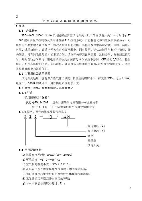
1.3 型式、规格、型号的组成及其代表意义1.3.1型式矿用隔爆型“E xdI”执行Q/HM13-2006 唐山开滦华明电器有限公司企业标准MT 871-2000 矿用隔爆型低压交流真空馈电开关1.3.2规格、型号的组成及其代表意义K B Z — / 1140额定电压(V)额定电流(A)真空隔爆型馈电开关1.4使用环境条件a)海拔高度不超过2000m (80~110KPa);b)环境温度:-5°C~+40°C;c)空气相对湿度不大于95%(+25°C);d)在具有甲烷及煤尘爆炸性气体混合物的危险场所;e)无破坏金属和绝缘材料的腐蚀性气体和蒸汽的场所;f)无显著摇动和剧烈冲击振动的环境;g)与水平安装倾斜度不超过15°;h)无滴水及水浸入、能防止雨雪的场所;i)污染等级:3级;j)安装类别:Ⅲ类。
2. 结构特征与工作原理2.1结构馈电开关由滑撬、隔爆外壳和安装在外壳主腔内的主控单元及通过铰链安装于外壳上的主腔门盖、接线箱等部份组成.2.2馈电开关使用说明(参照附图)一、合电前的准备:合上电源隔离开关GK1,B1变压器有电,二次侧220V绕组为断路器合闸线圈HQ供电;36V绕组为合闸中间继电器ZJ1供电;210V绕组为CPU和WYD供电;WYD输出48V为欠压脱扣继电器QY和分励继电器FL供电;CPU的M、L+端子输出24V直流,为扩展模块MK1-2供电、;80V绕组为传感器CG-U提供电源电压信号;27V绕组为漏电保护板LDB1、LDB2供电。
施耐德变频器及软起动器介绍

机械式
配套设备
燃气加热装置 燃油加热装置 锅炉及供暖
地铁、隧道、 大型建筑 家用空调机 空气处理机
组合式机组 新风机组
冷却塔风机 加湿器 ……
吸收式 地(水)源 式
风机盘管
户式中央空调 &大功率单元 式柜机
风管式 多联式 冷热水机组
Schneider Electric 2010 Solution Week
5 种尺寸 每一软起对应一种 标准电机额定功率
17
ATS22更容易集成和安装
● 内置旁路接触器
● 减少元器件 (接触器, 铜排, 外部电流传感器,等等) ● 简化接线和连接 ● 减少散热量,降低能耗
接线时 间缩短 50%
● 设计紧凑,比同类品牌节省20%以上空间 ● 全系列端子布局统一,上进线、下出线,方便接 线 ● 可拆卸控制端子
● 18.5kW以上标配直流电抗器 (380V产品)
Schneider Electric 2010 Solution Week 13
ATV61: 高性能标准转矩变频器
● 齐全的通讯协议: 标配Modbus和CANopen
● 所有主流工业总线+智能楼宇总线协议
● 风机、水泵运用宏
● 多泵切换卡 (Multi-pump card) ...
卡: I/O 扩展卡 通讯卡
可编程控制卡
“断电功能” 安全功能
Schneider Electric 2010 Solution Week
12
ATV61: 高性能标准转矩变频器
● 电压和功率范围:
● 200V~220V: 0.37-90kW ● 380V~480V: 0.75-1400kW ● 500V~690V: 2.2-2400kW
- 1、下载文档前请自行甄别文档内容的完整性,平台不提供额外的编辑、内容补充、找答案等附加服务。
- 2、"仅部分预览"的文档,不可在线预览部分如存在完整性等问题,可反馈申请退款(可完整预览的文档不适用该条件!)。
- 3、如文档侵犯您的权益,请联系客服反馈,我们会尽快为您处理(人工客服工作时间:9:00-18:30)。
PCB ordering information - page 30SERIES-INSULATOR STYLE-MATERIAL SERIES-INSULATOR STYLE-MATERIALMDB - Screw mounting-Diallyl phthalate MDVB - Screw mounting-Polyester H -Insulated solid or stranded wire L -Uninsulated solid wireS -Solder pot to accept #26 AWG max.harness wire.No designator - No hardware - standard mounting .091 (2.31) hole diameterP -JackpostK -Jackscrew-standard L -Jackscrew-low profile F -Float mountM -Military specification hardware, see page 13.1-.050 (1.27) centers9-15-21-25-31-37-51. See page 9P -Pin S - SocketCONTACT SPACIN GCONTACT ARRAN G EMENTCONTACT TYPECONTACT SPACIN G CONTACT ARRAN G EMENT CONTACT TYPE TERMINATION TYPE TERMINATION TYPELOC K IN G H AR DW ARE (SCRE W MOUNTIN GONLY )TERMINATION CO D E LOC K IN G H AR DW AREM D** 1-9P H 001P(H) 001 - 18",7/34strand, #26 AWG, MIL-W-16878/4,T ype E T eflon, Y ellow.(H) 003 - 18",7/34strand, #26 AWG, MIL-W-16878/4,T ype E T eflon, color coded to MIL-S T D-681System I.(L) 1 - 1/2"uninsulated solid #25 AWG gold plated copper.(L) 2 - 1"uninsulated solid #25 AWG gold plated copper.TERMINATION CO D ERo H S COMPLIANCERSee page 79 and 81for additional codesDimensions shown in inch (mm)Specifications and dimensions subject to changeHow to OrderMicrominiature Rectangular Connectors with MICRO-Pin Contacts on .050 (1.27)centers.MICRO-D microminiature rack/panel connec-tors are used in applications requiring highly reliable, extremely small, lightweight connec-tors. These connectors are available in 2 insu-lator materials, 2 mounting variations, 7 shell sizes accommodating from 9 to 51 contacts and a special arrangement of 5 micro contacts and 2 coaxials. The insulator materials listed give the MICRO-D connector wide versatility in most applications required by industry.ITT can also terminate a wide variety of stranded or solid wire directly to MICRO-D contacts, which is often desirable in high den-sity arrangements.MICRO-D connectors can also be custom har-nessed to meet any customer requirement of single or multiple connectors. Pigtail lead and harness description must be given by the cus-tomer. A typical description would be: .5" #25AWG, gold plated copper leads or 18" of #26yellow, Teflon-insulated, Type E wire. Shown below are various methods of termination.Consult customer service for any routine or complex harnessing of MICRO-D connectors.•Glass-filled diallyl phthalate thermoset material used in high temperature applica-tions that is immune to cleaning solvents.It also has excellent dielectric properties.Temperature range: -65˚F to +300˚F (-55˚C to +149˚C).•Glass-filled polyester thermoplastic that is not affected by cleaning solvents and exhibits excellent dielectric properties.Temperature range: -55˚F to +257˚F (-65˚C to +125˚C).SpecificationsMATERIALS AND FINISHESShell/Insulator (One Piece)MD/MDB: Glass-filledthermoset plastic MDV/MDVB: Thermoplastic ELECTRICAL DATA MECHANICAL FEATURES No of ContactsSize or Length Coupling PolarizationContact Spacing Centers Shell StylesConsult factory for availabilty.Coaxial CableWire SizeContact Termination -9to 51: (1 arrangement of 5 contacts and 2 coaxials - for screw mount only)-7sizes-Friction/jackscrews-Keystone-shaped shells -.050 (1.27mm)-Plug and receptacle-RG-178/U (Not available for MD clip mount)-#24 thru #32 AWG -Multi-indent crimp-Copper alloy, gold plateContactsDimensions shown in inch (mm)Specifications and dimensions subject to changeStandard Wire Termination CodesCavity #1 black*The following termination codes are listed for your information. For additional codes please refer to Appendix on page 79 and 81. All wire lengths are minimum.#26 A WG per MIL-W-16878 Type E Teflon ,stranded.H arness Typ e (H)L ength 3(76.2)6(152.4)8(203.2)10(254.0)12(304.8)18 (457.2)20(508.0)24(609.6)30(762.0)36(914.4)48(1219.2)72(1828.8)120(3048.0)H020H019H026H029H028H001H038H009H010H011H013H017H042H027H016H034H025H002H003H023H004H005H006H048H046H041L61L 56L 57L 39L 58L 1L 14L2L 7L6L 16L 10.125(3.18).150 (3.81).190(4.83).250 (6.35).375(9.52).500 (12.70).750 (19.05)1.000 (25.40)1.500 (38.10)2.000 (50.80)2.500 (63.50)3.000 (76.20)All Y ell o w Co l o r Cod e d*T erminati o n Cod eL ength #25A WG G old P lated CopperS o li d U ninsulate d Typ e (L)With Screw Mounting Holes (Conforms to MIL-DTL-83513)MDB.110(2.79)MAX..154(3.91)(5.08)MAX.Solder PotSolder PotGlass-filled Diallyl Phthalate Plastic InsulatorMDVBGlass-filled Polyester Plastic InsulatorRPart Number by Shell Size Add lead type and length, see Part Number Explanation.Weight given is with 1/2", uninsulated solid #25 AWG gold plated copper pigtails.*****AMax.B Max.C Max.D Max.E Max.F ±.005Avg.Weight***±5% (oz.)±5% (gm.)MDB1-9S**MDB1-15P**MDB1-15S**MDB1-21P**MDB1-21S**MDB1-25P**MDB1-25S**MDB1-31P**MDB1-31S**MDB1-37P**MDB1-37S**MDB1-51P**MDB1-51S**MDVB1-9S**MDVB1-15p**MDVB1-15S**MDVB1-21P**MDVB1-21S**MDVB1-25P**MDVB1-25S**MDVB1-31P**MDVB1-31S**MDVB1-37P**MDVB1-37S**MDVB1-51P**MDVB1-51S**.788 (20.02).788 (20.02).938 (23.82)1.088 (27.64)1.088 (27.64)1.188 (30.18)1.188 (30.18)1.338 (33.98)1.338 (33.98)1.488 (37.80)1.488 (37.80)1.438 (36.52)1.438 (36.52).292 (7.42).380 (9.65).442 (11.23).592 (15.04).680 (17.27).692 (17.58).780 (19.81).842 (21.39).930 (23.62).992 (25.20)1.080 (27.43).942 (23.93)1.030 (26.16).408 (10.36).408 (10.36).588 (14.17).708 (17.98).708 (17.98).808 (20.56).808 (20.56).958 (24.33).958 (24.33)1.108 (28.14)1.108 (28.14)1.058 (26.87)1.058 (26.87).173 (4.39).173 (4.39).173 (4.39).173 (4.39).173 (4.39).173 (4.39).173 (4.39).173 (4.39).173 (4.39).173 (4.39).173 (4.39).220 (5.59).220 (5.59).218 (5.54).218 (5.54).218 (5.54).218 (5.54).218 (5.54).218 (5.54).218 (5.54).218 (5.54).218 (5.54).218 (5.54).218 (5.54).260 (6.60).260 (6.60).565 (14.35).565 (14.35).715 (18.16).865 (21.97).865 (21.97).965 (24.51).965 (24.51)1.115 (28.32)1.115 (38.32)1.265 (32.13)1.265 (32.13)1.215 (30.86)1.215 (30.86).026 (0.73).025 (0.70).038 (1.10).053 (1.50).050 (1.40).063 (1.80).056 (1.60).080 (2.30).073 (2.10).086 (2.45).076 (2.15).109 (3.10).093 (2.64)Dimensions shown in inch (mm)Specifications and dimensions subject to changeMD*B-PCB connectors use standard MD*B all plastic shells and are designed for use with flex circuitry, printed circuit and multi-layer boards. They are easily mounted and soldered and provide high density/high reliability in board-to-board and board-to-cable applica-tions. While being similar to the MDM-PCB connectors, the MD*B-PCB connectors are all plastic, extremely small, and lightweight yet rugged enough for use in the most demanding applications.MD*B-PCB connectors are available inseven shell sizes with 9 to 51 contacts in the popular 90°narrow profile PCB termination,with a variety of tail lengths for varying boardthickness.How to OrderSERIESCONTACT ARRANGEMENT CONTACT TYPE CTERMINATION TYPE THARDWAREHTERMINATION TAIL LENGTH TMODIFICATION CODES C(Consult Factory)MMD*B--37S CBR ** * *L39RoHS COMPLIANCE RJackpost mounting for use with locking hard-ware is also available.If the connectors shown in the catalog do not meet the requirements of your applica-tions, a special shape, size or layout using the basic all plastic shell can be made avail-able. For further technical and applications information, contact customer service.CONNECTOR SERIES MDVB, MDBCONNECTOR ARRANGEMENT9, 15, 21, 25, 31, 51CONTACT TYPES =Socket P =PinTERMINATION TYPECBR = 90°Narrow Profile PCB Terminations HARDWAREP =JackpostM7 = Jackposts, M635135-07No Letter = Less HardwareTERMINATION TAIL LENGTH CODESNONE –.109 (2.77) ±0.15 (0.38) Standard L61– .125 (3.18)L66– .150 (3.81)L57– .190 (4.83)L39–.250 (6.35)L58– .375 (9.52)Dimensions shown in inch (mm)Specifications and dimensions subject to changeCBR Series (90˚ Mounting Narrow Profile)TYP ..186 (4.72) PLUG 9-15-21-25 VIEW*FOR 31: 1.085 (27.56) MAX. FOR 37: 1.185 (30.10) MAX. FOR 51: 1.225 (31.12) MAX.I A. TYPPCB Termination Arrangements (Viewed from bottom of connector, on PCB solder side.)Indentification number shown for plug connector, use reverse order for socket connector..083.020.0209Contacts15 Contacts21 Contacts 25Contacts51 Contacts37 Contacts31 ContactsAll Termination Configurations .100 (2.54) x .100 (2.54) Grid Pattern, Offset .050 (1.27)*For jackpost locking add letter "P" or "M7".NOTE: Standard lead termination is #24 AWG, solid copper, solder or tin dipped.Part Number By Shell Size MD*B-9PCBR*MD*B-9SCBR*MD*B-15PCBR*MD*B-21PCBR*MD*B-21SCBR*MD*B-25PCBR*MD*B-25SCBR*MD*B-31PCBR*MD*B-31SCBR*MD*B-37PCBR*MD*B-37SCBR MD*B-51PCBR*MD*B-51SCBR.788 (20.01).938 (23.82)1.088 (27.63)1.088 (27.63)1.188 (30.17)1.188 (30.17)1.338 (33.98)1.338 (33.98)1.488 (37.79)1.488 (37.79)1.438 (36.52)1.438 (36.52).565 (14.35).715 (18.16).865 (21.97).865 (21.97).965 (24.51).965 (24.51)1.115 (28.32)1.115 (28.32)1.265 (32.13)1.265 (32.13)1.215 (30.86)1.215 (30.86).292 (7.42).525 (13.34).592 (15.04).675 (17.14).692 (17.58).775 (19.68).842 (21.39).925 (23.50).994 (25.25)1.075 (27.30).942 (23.93)1.026 (26.06).218 (5.54).218 (5.54).218 (5.54).218 (5.54).218 (5.54).218 (5.54).218 (5.54).218 (5.54).218 (5.54).218 (5.54).258 (6.55).258 (6.55).134 (3.40).218 (5.54).134 (3.40).218 (5.54).134 (3.40).218 (5.54).134 (3.40).218 (5.54).134 (3.40).218 (5.54).177 (4.50).258 (6.55).420 (10.67).420 (10.67).420 (10.67).420 (10.67).420 (10.67).420 (10.67).420 (10.67).420 (10.67).520 (13.21).520 (13.21).550 (13.97).550 (13.97).250 (6.35).250 (6.35).250 (6.35).250 (6.35).250 (6.35).250 (6.35).250 (6.35).250 (6.35).250 (6.35).250 (6.35).300 (7.62).300 (7.62).230 (5.84).130 (3.30).130 (3.30).130 (3.30).130 (3.30).130 (3.30).130 (3.30).130 (3.30).130 (3.30).130 (3.30).150 (3.81).150 (3.81)A Max.B±.005 (0.13)G±.010 (0.25)H±.010 (0.25)C Max.D Max.E Max.F Max.Dimensions shown in inch (mm)MDB Coaxial Series with Screw Mounting HolesMDB connectors with two coaxial and five MICRO-PIN TM /MICROSOCKET TM contacts. Crimp-type coaxial contacts accommodate RG-178/U cables. A plastic insertion/extraction tool is supplied with each connec-tor assembly having removable coaxial assembly.How to Order - MDB CoaxialSERIESMDB1-7C2****SHKSERIESMicro-D CoaxialNo Letter - Coaxial assemblyinstalled and nonremovable RO - coaxial assembly ordered serparatelyRA - Coaxial shipped assembled but uninstalled See Standard Wire TerminationConsult customer serviceNo letter - No hardware*Not available with removalbe coax cable type connectors RO and RA.standard mounting. 091 (2.31) hole diameter F -FloatK -Jackscrew (standard)L -Jackscrew (low profile)P -JackpostCode on page 29. Coaxial cable will beRG-178U unless otherwise specified; length will be same as wire modification.P -Pin S -Socket L -Uninsulated, solid wireH -Insulated, solid or stranded S -Solder pot*1-.050 (1.27) centers...................7 (2)SIGNAL CONTACT SPACING TOTAL CONTACT CAVITIES NUMBER OF COAXIALS SIGNAL CONTACT SPACING TOTAL CONTACT CAVITIES NUMBER OF COAXIALS COAXIAL TYPECOAXIAL TYPESIGNAL CONTACT TYPE SIGNAL CONTACT TYPESIGNAL CONTACT LEAD TYPE SIGNAL CONTACT LEAD TYPESIGNAL CONTACT LEAD LENGTH SIGNAL CONTACT LEAD LENGTH MODIFICATIONHARDWAREMODIFICATION HARDWARERoHS COMPLIANCE RHow to Order - Coaxial Cable AssembliesSERIESMDCCS** * *COAXIAL CABLE CONTACT TYPE CONTACT TYPE COAXIAL CABLE TYPECOAXIAL CABLE TYPE COAXIAL CABLE LENGTHCOAXIAL CABLE LENGTHSERIES MDP -Pin(used with socket side connection)S -Socket(used with pin type connection)See Standard Wire TerminationCodes on page 29. Coaxial cable will be RG-178U unless otherwise specified; length will be the same as wire modfication.1-RG178/UCOAXIAL CABLE CCRoHS COMPLIANCE RDimensions shown in inch (mm)Specifications and dimensions subject to changeDimension - MDB Coaxial SeriesPlugReceptacle(See page 9 for layouts)Part Numberby Shell SizeMDB1-7C2P*MDB1-7C2S*.510 (12.95).602 (15.29)* Add lead type and length, see Part Number Explanation.** Weight given is with 7 inch (177.80) insulated leads, #26 AWG silver plated copper pigtails and RG178/U coaxials..204 (5.18).185 (4.70).298 (7.57).279 (7.09).782 (19.86).782 (19.86).395 (10.03).375 (9.52).510 (12.95).540 (13.72).290 (8.30).273 (7.80)A Ma x.B Ma x.C Ma x.E Ma x.E 1Ma x.D +_.005 (0.13)Av g .W eight**(oz)+_5% (gm .)+_5%TWO MTG. HOLES RO AND RA COAXESRO AND RA COAXESMounting Hardware Views (Sizes 9-51)This hardware supplied unassembled.Screw Lock Assembly90˚ Angle Mounting BracketDescriptionScrew Lock Assembly Jackpost Kit322-9500-000 320-9505-000015-9516-000 .100 (2.54) .122 (3.10) .257(6.53).215(5.46)015-9516-000 Mounting Bracket, 90˚ Angle- MD*1for 9 thru 37 Shell Sizes MD*1for 51 Shell SizeNOTES: Screw lock assembly (322-9500-000) can be used for front front mounting. Jackpost kit(320-9505-000) consists of 2 assemblies, shipped unassembled.Part Number ±.005 (0.13)Max.*NOTE: Torque value is 4.0 in/lbs max. REF. ONLY_.003_0.08)FACEFACECONNECTOR HEX HEAD -Jackscrew - (L) Low ProfileJackscrew - (K) StandardThis hardware is factory installed.Shown here is a cutaway view of the float mount for the MD connector.The basic shell dimensions are the same for the float mount and the screw mounting hole configurations. View shown is for standard float mount front panel mounting. Reverse mounting is available on request.*NOTE: Torque values are as follows: Low Profile Jackscrew (L)-2.5 in/lbs Standard Jackscrew (K)-2.5 in/lbsDimensions shown in inch (mm)Specifications and dimensions subject to changeMounting Hardware to Military Specification (Sizes 9 - 51) PER MIL-DTL-83513/5This hardware supplied unassembled.Jackscrew - (L) Low profile *.062 (1.57)HEX. (REF.).092 (2.34) DIA.Allen headPlug and Receptacle Low and High Profile Slotted HeadJackpost AssemblyDescriptionSlotted Head Jackscrew Assy Low ProfileSlotted Head Jackscrew Assy High Profile Allen Head Jackscrew Assy Low Profile Allen Head Jackscrew Assy High Profile Jackpost Assy-05-06-02-03-07M5M6M2M3M7320-9508-025320-9508-027320-9508-026320-9508-028320-9505-033M83513/5Mode Code Part Number ThreadJackpost Bushing (For Rear Panel Mounting)MATING FACE.126 (3.20).125 (3.18)DIA.TYP .+.005 (0.13)3/32 (2.4)1/16 (1.6)3/64 (1.2)1/32 (0.8).092/.087 (2.34/2.21).061/.056 (2.34/1.42).047/.042 (1.19/1.07).030/.025 (0.76/0.64)320-9505-007320-9505-006320-9505-005320-9505-0049152125313751.379 ( 9.63).529 (13.44).679 (17.25).779 (19.79).929 (23.60)1.079 (27.41)1.029 (26.14).219 (5.56).219 (5.56).219 (5.56).219 (5.56).219 (5.56).219 (5.56).261 (6.63).565 (14.35).715 (18.16).865 (21.97).965 (24.51)1.115 (28.32)1.265 (32.13)1.215 (30.86)*2Jackposts, 2nuts, 2washers .Panel Thickness A Dim.Jackpost Kit Number*A+.004 (0.10)-.000 (0.00)Shell SizePlug and Receptacle DimensionsB +.004 (0.10)-.000 (0.00)C +_.005(0.13)NOTE: Torque value for jackpost 2.5 in /lbsPanel Mounting Dimensions.200 ±.005Plug and ReceptacleRear MountedPlug and Receptacle Front Mounted Plug Front Mounted Receptacle Rear Mounted.300 ±.005Dimensions shown in inch (mm)Specifications and dimensions subject to changePanel CutoutsFigure 1Front Mounting+.005 (0.13) R TYP -.000 (0.00)Figure 2Rear MountingFigure 3Edgeboard MountingNOTES:1. 2. 3. 123123123123123123123.409 (10.39).379 ( 9.63)-.559 (14.20).529 (13.44)-.709 (18.00).679 (17.25)-.809 (20.55).779 (19.79)-.959 (24.36).929 (23.60)-1.109 (28.17)1.079 (27.41)-1.059 (26.90)1.029 (26.14)-.172 (4.37).219 (5.56)-.172 (4.37).219 (5.56)-.172 (4.37).219 (5.56)-.172 (4.37).219 (5.56)-.172 (4.37).219 (5.56)-.172 (4.37).219 (5.56)-.215 (5.46).261 (6.63)-.570 (14.48).570 (14.48).570 (14.48).720 (18.29).720 (18.29).720 (18.29).870 (22.10).870 (22.10).870 (22.10).970 (24.64).970 (24.64).970 (24.64)1.120 (28.45)1.120 (28.45)1.120 (28.45)1.270 (32.26)1.270 (32.26)1.270 (32.26)1.220 (30.99)1.220 (30.99)1.220 (30.99).089 (2.26).089 (2.26).089 (2.26).089 (2.26).089 (2.26).089 (2.26).089 (2.26).089 (2.26).089 (2.26).089 (2.26).089 (2.26).089 (2.26).089 (2.26).089 (2.26).089 (2.26).089 (2.26).089 (2.26).089 (2.26).089 (2.26).089 (2.26).089 (2.26)9152125313751A+.004 (0.10)-.000 (0.00)B+.004 (0.10)-.000 (0.00)C+.005 (0.13)-.000 (0.00)D+.005 (0.13)-.000 (0.00)Cutout Figure Size Front mounting (figure 1) and rear mounting (figure 2) accommodates #2-56 screws.Front mounting is preferred. However, when rear mounting is necessary. use detail on previous page.Edgeboard mounting bracket (figure3) uses #2-56 screws. Dimension .450 ± .002 (11.43 ± 0.05) locates theMD receptacle flush with the end of the board.PlugMDGlass-filled Diallyl Phthalate Plastic InsulatorMDVGlass-filled Polyester Plastic InsulatorSolder PotSolder PotReceptacle.130(3.30)(5.33)(4.32).170(4.32)PCB ordering information - page 30SERIES-INSULATOR STYLE-MATERIAL SERIES-INSULATOR STYLE-MATERIALMD - Clip mounting -Diallyl phthalate MDV - Clip mounting-Polyester H-Insulated solid or stranded wire L -Uninsulated solid wireS -Solder pot to accept #26 AWG max.harness wire.No designator - No hardware - standard mounting .091 (2.31) hole diameterNot available in clip mounting.See page 79 and 81for additional codes.***(H) 001 - 18", 7/34strand ,#26 AWG ,MIL-W-16878/4, T ype E T eflon ,Y ellow.(H) 003 - 18", 7/34strand ,#26 AWG ,MIL-W-16878/4, T ype E T eflon ,colorcoded to MIL-S T D-681 System I.(L) 1 - 1/2"uninsulated solid #25AWG gold plated copper.(L) 2 - 1"uninsulated solid #25AWG gold plated copper.1-.050(1.27) centers9-15-21-25-31*-37-51.See page 7P -Pin S - Soc k etCONTACT SPACIN GCONTACT ARRAN G EMENTCONTACT TYPECONTACT SPACIN G CONTACT ARRAN G EMENT CONTACT TYPE TERMINATION TYPE TERMINATION TYPETERMINATION CO D E **TERMINATION CO D E LOC K IN G H AR DW AREM D1-9PH001PRo H S COMPLIANCERPart Number by Shell Size MD1-9P**MD1-9S**MD1-15P**MD1-15S**MD1-21P**MD1-21S**MD1-25P**MD1-25S**MD1-37P**MD1-37S**MD1-51P**MD1-51S**MDV1-9-P**MDV1-9S**MDV1-15P**MDV1-15S**MDV1-21P**MDV1-21S**MDV1-25P**MDV1-25S**MDV1-37P**MDV1-37S**MDV1-51P**MDV1-51S**A Max.B Max.C Max.D Max.E Max.Avg. Weight***±5% (oz.)/±5% (gm.).512 (13.00).512 (13.00).662 (16.81).662 (16.81).812 (20.62).812 (20.62).912 (23.16).912 (23.16)1.212 (30.78)1.212 (30.78)1.162 (29.51)1.162 (29.51).292 (7.42).376 (9.55).442 (11.23).526 (13.36).592 (15.04).676 (17.17).692 (17.58).776 (19.71).992 (25.20)1.076 (27.33).942 (23.93)1.026 (26.06).405 (10.29).405 (10.29).555 (14.10).555 (14.10).705 (17.91).705 (17.91).805 (20.45).805 (20.45)1.105 (28.07)1.105 (28.07)1.055 (26.80)1.055 (26.80).170 (4.32).170 (4.32).170 (4.32).170 (4.32).170 (4.32).170 (4.32).170 (4.32).170 (4.32).170 (4.32).170 (4.32).213 (5.41).213 (5.41).215 (5.46).215 (5.46).215 (5.46).215 (5.46).215 (5.46).215 (5.46).215 (5.46).215 (5.46).215 (5.46).215 (5.46).258 (6.55).258 (6.55).026 (0.73).026 (0.73).038 (1.10).035 (1.00).053 (1.50).050 (1.40).063 (1.80).056 (1.60).086 (2.45).076 (2.15).109 (3.10).093 (2.65)How to OrderWith Clip Mounting SlotsMicro-D Plastic Shell - .050" Contact Spacing MD**Panel Mounting HardwareClip MountingDescriptionDimensions (Clip Mounting Only)Coupling Retention Clip(see Figure 2)Mounting Screw Brackets(see Figures 1 and 3)PanelMounting KeyEdgeboard Mounted(see Figure 4)Plug and ReceptacleRear MountedPlug and ReceptacleFront Mounted Receptacle Rear MountedPart Number201-9100-000294-9100-000015-9100-000015-5009-000MD51428-1Panel Mounting KeyMounting Key and Coupling Clip AssemblyMounting Screw BracketEdgeboard Mounting BracketEdgeboard Mounting Bracket andCoupling Clip AssemblyMust be ordered separately; specify left and right hand for completeassembly.Must be ordered separately; assembly contains set of left and righthand types.******Illustrated is the recommended method of front mountingwith metal panel mounting keys. Panel mounting keys areavailable with or without coupling retention clips.For front mounting,place the rear of the connector thruthe panel cutout.With the mounting flange against thepanel,fully insert the panel mounting keys thru the slotsin the flange and thru the panel cutout.Retaining thekeys in this position, bend them outward against the rearof the panel.When mating a front mounted connectorwith an unmounted connector, a coupling retention clipassembly may be used to securely lock the two together.Mounting screw brackets are available and may be usedinstead of the panel mounting keys.Panel CutoutsFigure 1Figure 3Rear MountingFigure 4Edgeboard MountingFigure 2Front Mounting.).).MAX. (TYP.)A panel thickness of 1/8" 3.17mm) maximum is recommended for ease of tab bendingwhen a panel mounting key & clip assembly or edgeboard mounting brackets are used.Front mounting is preferred. However, when rear mounting is necessary, use figure 3 fordimensions.Figure 4 is for edge board mounting bracket or edgeboard clip assembly. The .184 +_ .0022.67 +_ 0.05) dimension locates the MD socket insulator flush with the end of the board.Screw brackets (015-9100-000) will accommodate #2-56 screws.Front mounting(Figure 1)and rear mounting(Figure 3)accommodate#2-56screws.1.2.3.4.5.ShellSize91521253751123412341234123412341234.408 (10.36).408 (10.36).378 ( 9.60).400 (10.16).588 (14.94).588 (14.94).528 (13.28).550 (13.97).738 (18.75).738 (18.75).678 (17.27).700 (17.78).838 (21.29).838 (21.29).778 (19.76).800 (20.32)1.138 (28.91)1.138 (28.91)1.078 (27.38)1.100 (27.94)1.088 (27.64)1.088 (27.64)1.028 (26.11)1.050 (26.67).172 (4.37).172 (4.37).217 (5.51).091 (2.31).172 (4.37).172 (4.37).217 (5.51).091 (2.31).172 (4.37).172 (4.37).217 (5.51).091 (2.31).172 (4.37).172 (4.37).217 (5.51).091 (2.31).172 (4.37).172 (4.37).217 (5.51).091 (2.31).215 (5.46).215 (5.46).260 (6.60).091 (2.31).650 (16.51)-.650 (16.51)-.795 (20.19)-.795 (20.19)-.945 (24.00)-.945 (24.00)-1.045 (26.54)-1.045 (26.54)-1.345 (34.16)-1.345 (34.16)-1.295 (32.89)-1.295 (32.89)-.089 (2.26)-.089 (2.26)-.089 (2.26)-.089 (2.26)-.089 (2.26)-.089 (2.26)-.089 (2.26)-.089 (2.26)-.089 (2.26)-.089 (2.26)-.089 (2.26)-.089 (2.26)-CutoutFigureA+.004 (0.10)-.000 (0.00)B+.004 (0.10)-.000 (0.00)C+.004 (0.10)-.000 (0.00)D+.005 (0.13)-.000 (0.00)38Dimensions shown in inch (mm)Specifications and dimensions subject to change 元器件交易网。
