TRV-3800中文资料
TRV-xxx中文资料
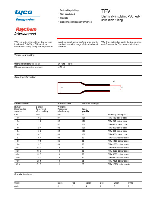
Temperature ratingOrdering informationStandard coloursOperating temperature range:-30°C to +105°C Minimum recovery temperature:+150°CInside diameter Wall thickness Standard package D (min)Expanded as supplied d (max)Recovered after heating W (nom)Recovered after heating Spool quantity mm mm mm m Ordering description 1.60.80.4100TRV-160-colour code 2.4 1.20.5100TRV-240-colour code 3.2 1.60.5100TRV-320-colour code 4.8 2.40.5100TRV-480-colour code 6.4 3.20.5100TRV-620-colour code 9.5 4.50.6100TRV-950-colour code 12.7 6.40.850TRV-1270-colour code 15.07.50.850TRV-1500-colour code 19.09.50.850TRV-1900-colour code 25.412.7 1.050TRV-2540-colour code 32.016.0 1.050TRV-3200-colour code 38.019.0 1.050TRV-3800-colour code 51.025.5 1.050TRV-5100-colour code 76.038.1 1.025TRV-7625-colour code 102.051.01.325TRV-10200-colour codeColour Black Red Yellow Blue Green White Code24569•Self extinguishing •Non-irradiated •Flexible•Good mechanical performanceTRVElectrically insulating PVC heat-shrinkable tubingTRV is a self extinguishing, flexible, non-irradiated, Poly Vinyl Chloride heat-shrinkable tubing. The product provides excellent mechanical performance and is resistant to a wide range of chemicals and solvents.TRV finds extensive use in the Automotive and Commercial Electronics industries.Raychem Interconnect Cheney Manor Industrial Estate Swindon, Wiltshire SN2 2QE Tel:(44)-1793-528171 Fax:(44)-1793-616652All of the above information, including illustrations, is believed to be reliable. Users, however, should independently evaluate the suitability of each product for their application. Tyco Electronics makes no warranties as to the accuracy or completeness of the information and disclaims any liability regarding its use. Tyco Electronics only obligations are those in the Standard Terms and Conditions of Sale for this product and in no case will Tyco Electronics be liable for any incidental, indirect or consequential damages arising from the sale, resale, use or misuse of the product. Tyco Electronics Specifications are subject to change without notice. In addition Tyco Electronics reserves the right to make changes in materials or processing, without notification to the Buyer, which do not affect compliance with any applicable specification.TRVRI0037.1299 Raychem and TRV are trademarks of Raychem Interconnect, a division of Tyco Electronics Corporation.PerformanceSpecifications Heat ageing:168 h at 136°C UL 224 Corrosion resistance:No corrosion ASTM D2671 Dielectric strength:15 MV/m min IEC 243Fluid resistance 24h at 23°C, ISO 37:Tensile strength 12 MPa (min)Elongation 150% (min)Test Fluids:IRM 902Lubricating oil 0-149Anti-icing fluidFlammability:Pass UL 224 VW1For full product performance details consult Raychem Specification RK 6147/1. Raychem Specification RK 6147/1.。
Honeywell扫描枪3800g产品简介
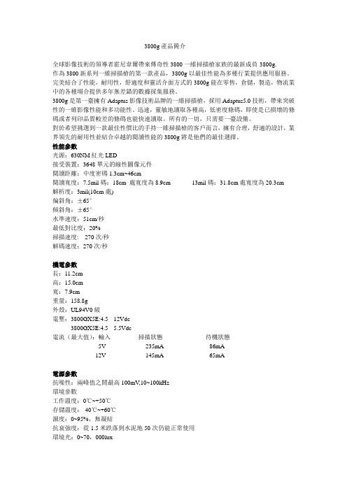
3800g產品簡介全球影像技術的領導者霍尼韋爾帶來傳奇性3800一維掃描槍家族的最新成員-3800g.作為3800新系列一維掃描槍的第一款產品,3800g以最佳性能為多種行業提供應用服務。
完美結合了性能,耐用性,舒適度和靈活介面方式的3800g能在零售,倉儲,製造,物流業中的各種場合提供多年無差錯的數據採集服務。
3800g是第一臺擁有Adaptus影像技術品牌的一維掃描槍,採用Adaptus5.0技術,帶來突破性的一維影像性能和多功能性。
迅速,靈敏地讀取各種高,低密度條碼,即使是已損壞的條碼或者列印品質較差的條碼也能快速讀取。
所有的一切,只需要一臺設備。
對於希望挑選到一款最佳性價比的手持一維掃描槍的客戶而言,擁有合理,舒適的設計,業界領先的耐用性並結合卓越的閱讀性能的3800g將是他們的最佳選擇。
性能參數光源:630NM紅光LED接受裝置:3648單元的線性圖像元件閱讀距離:中度密碼1.3cm~46cm閱讀寬度:7.5mil碼:18cm 處寬度為8.9cm 13mil碼:31.8cm處寬度為20.3cm解析度:3mil(10cm處)偏斜角:±65°傾斜角:±65°水準速度:51cm/秒最低對比度:20%掃描速度: 270次/秒解碼速度:270次/秒機電參數長:11.2cm高:15.0cm寬:7.9cm重量:158.8g外殼:UL94V0級電壓:3800GX5E:4.5 --12Vdc3800GX5E:4.5 --5.5Vdc電流(最大值):輸入掃描狀態待機狀態5V 235mA 86mA12V 145mA 65mA電源參數抗噪性:兩峰值之間最高100mV,10~100kHz環境參數工作溫度:0℃~+50℃存儲溫度:-40℃~+60℃濕度:0~95%,無凝結抗衰強度:從1.5米跌落到水泥地50次仍能正常使用環境光:0~70,000lux防靜電保護:經15KV放電後仍能正常工作抗震動性:經受從20~300Hz的5G峰值震動測試認證:國際:CB scheme to IEC 60825-1 Class 1LED.美國:FCC Part 15 subpart B Class B,UL Listed to 60950-1加拿大:ICES-003Class B.cUL Listed to CSA C22.2 No.60950-1-03.歐洲:CE2004/EC EMC Directive to EN55022 Class B.EN55024,EN61000-3-2,EN61000-3-3.2006/95/EC Low Voltage Directive.GS Mark:GS marked for I.T.E safety 墨西哥:NOM-NYCE.韓國:MIC Class A.澳大利亞、新西蘭:C-Tick mark 平均故障間隔時間:符合美軍標準MIL-HDBK-217F 非移動地面設備測試可無故障使用100.000小時碼制:庫德巴碼,39碼,交叉25碼,工業標準25碼,矩陣25碼,11碼,93碼,128碼,UPC碼,EAN/JAN碼,中國郵政碼,GS 1 DataBar,2005Sunrise/GTIN compliant,ISBT 128 串聯(執照需付費)介面:3800GX5E:通過鍵盤口,鍵盤置換/直連,USB口,TTL級RS-232,連接各種主流PC,IBM 46XXX系列零售終端和零售USB介面3800GX4E:通過鍵盤口,鍵盤置換/直連,USB口,TTL級RS-232,連接各種主流PC 和終點介面。
3800大说明书新(1)

ED3800开环电流矢量变频器产品使用说明书深 圳 市 易 驱 电 气 有 限 公 司总部:深圳市福田区八卦三路光纤小区3栋6楼 研发生产基地:深圳市龙华街道油松东环二路靖轩工业园11栋前 言ED3800系列变频器是我公司自主研发的第二代高性能矢量控制变频器,其采用了全新的设计理念和模块化的设计思想。
和传统的变频器相比较,无论在性能、功能、可靠性、可维护性及可使用性等方面,均有本质的提升。
其具体表述为:强大的控制平台ED3800系列变频器控制核心基于32位的RISC单片机,其运算速度达到了惊人的1.3DMIPS,高效完成复杂的电机控制算法,能实现真正的实时控制。
丰富的硬件外设极大提高系统的集成度和可靠性。
领先的控制算法在电机核心控制层,ED3800创新性的将矢量控制和VF控制技术完美结合,引入磁通控制的思想,即使在VF控制模式下也能达到良好的电机控制效果,同时对电机参数变化不敏感,极大的提高了系统控制的鲁棒性。
矢量控制方面,采用了经典的基于转子磁场定向原理的矢量控制技术,基于磁通观测器原理,在转子磁链方向上对电机的磁通电流与转矩电流进行解耦,并分别加以控制。
采用了速度自适应观测器(MARS)对转子速度全程进行估计。
在控制结构上采用经典的三闭环控制结构即位置环(5000系列)、速度环与电流环,从而实现了全方位的位置,速度与转矩控制。
开放式的硬件架构ED3800系列变频器提供了具有强大扩展能力的SPI接口,开放式的标准MODBUS协议,客户可在此基础上以扩展卡的形式实现任意的行业专用功能,而无需更改主机的硬件或软件设计,极大的方便了客户的二次开发。
强悍的功能ED3800系列变频器功能的强悍不仅仅体现在功能的丰富,更多的体现在对传统功能的优化和创新设计,同时引领行业化设计的潮流,在以下功能设计上均采用了诸多创新设计。
独特的电源与EPS功能,能将一台变频器当做一台变频电源或EPS运行,具备面向电源行业的二次开发与系统集成功能,其意义已突破了传统变频器的概念。
汕头超声Apogee3800介绍
Apogee 3800
强大的数据管理
卖点回顾:
1、先进的技术:高精度波束合成技术、宽频带频率融合技术、声速补偿
优化技术、反向组织谐波技术、EPI拓展脉冲成像技术、空间复合成像技术 、斑点柔化技术(多档可调)、血流增强技术、彩色优先度等。
2、人性化的外观设计:触摸屏操作、360度自由控制17寸液晶监示器及
先进的成像技术
反相谐波成像 多模式谐波成像
基波信号相互抵消 谐波信号成倍增强
Apogee 3800
先进的成像技术
声速补偿优化成像
不同密度的组织之间呈现 合理的回声强度差异 组织间边界清晰可辨 有利于 发现早期病变
Apogee 3800
先进的成像技术
EPI拓展脉冲成像
常规发射成像
发射波形 正常组织回波 随机噪声回波 发射波形
系统自动跟踪识别有效信息,对这些信息进行强化,并 滤除噪声,提高信噪比
基于直方图分布的B型图像优化
百分比
30%
0
自动优化 百分比
255
图谱显示范围 和 灰阶 基线位置自动调整 的频谱优化
自动优化
10%
灰阶
0
255
Apogee 3800
先进的成像技术
彩色增强技术
让彩色的充盈变得更加自如
彩色优先度技术
双幅实时对照
血流与二维结构 实时对照观察 有利于诊断判别
彩色隐藏技术 方向能量图
Apogee 3800
丰富的临床解决方案
灵敏实用的多普勒分析
脉冲波多普勒、连续波多普勒频谱 为血流动力学分析提供坚实的保障
自动识别 基线上或 下方频谱 进行包络
多普勒三变频 实时三同步 多种包络测量模式自由选择
3800路由器设备参数
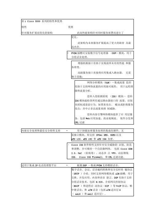
此平台为集中和分发式呼叫处理提供了可扩展性:I 带集中 Cisco CallManager 的SRST —多达480个电话I Cisco Unity Express (CUE)语音留言一多达100个邮箱I Cisco CallMa nager Express IP 电话一24到240个IP电话各种规模的分支机构连接一多达24条T1/E1中继模拟电话、传真机、按键系统和会议工作站一多达88个FXS端口»米用EVM模块的本地或远程呼叫—多达48个外部交换局(FXO)或32个基本速率接口(BRI)端口Cisco IOS软件提供了定制特性和应用,如工具命令语言(TCL)和话音可扩展标记语言(VXML)支持。
使用Cisco 3800,就可通过CiscoCallManager和思科IP电话实现安全呼叫:・使用IPSec、传输层安全(TLS )和安全实时协议(SRTP ),为IP电话间、 IP电话到模拟电话或公共交换电话网络(PSTN)网关提供了基于标准的安全介质和信令验证及加密。
保持中高度复杂的编译码器的信道容量。
投资保护・Cisco 3800系列上支持可现场升级的模块化组件,使客户无需升级整个分支机构网络即能方便地更改网络接口。
Cisco 3800系列利用了现有 WIC、VIC、网络模块和 AIM系列,降低了备份、培训、配置、安装和维护成本。
可用性«Cisco 3800系列通过可用性特性而缩短了停机时间,其中包括可选冗余电源、用于改进故障隔离和修复的错误检查和修复(ECC)内存、用于方便地恢复镜像的 USB闪存、先进的温度监控和变速风扇、用于缩短启动时间的 Cisco IOS软件热重启、网络模块在线插拔,以及风扇、主板和电源等可现场更换的组件(仅限 Cisco 3845 )。
存、用于保护Cisco IOS软件配置分发的安全令牌和VPN证书的平台外存储共用)总结Cisco 3800系列将最佳路由、安全和话音技术内嵌入路由器架构,使企业可安全地以线速提供并发的关键任务型服务和应用。
定位器 3800SA Bulletin
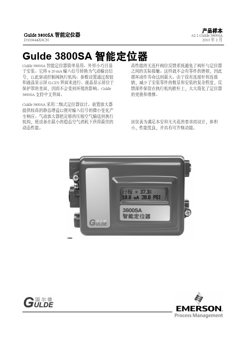
D103644X0CN2013年2月Gulde3800SA智能定位器Gulde3800SA智能定位器简单易用、外形小巧且易于安装。
它将4-20mA输入信号转换为气动输出信号,以此驱动控制阀执行机构。
参数设置通过按钮和液晶显示屏(LCD)界面来进行。
液晶显示屏位于保护罩的里面,因而不会受到环境的影响。
Gulde 3800SA支持中文界面。
Gulde3800SA采用二级式定位器设计。
前置放大器提供较高的静态增益以便对输入信号的微小变化产生响应。
气动放大器把足够的压缩空气输送到执行机构,使设备在最小的稳态空气消耗下获得最佳的动态性能。
高性能的无连杆阀位反馈系统避免了阀杆与定位器之间的实际接触。
这样就不会有零件的磨损,因此循环动作寿命达到最大。
由于没有连接杆和连接销,减少了安装零件的数量和安装的复杂程度,反馈部件保留在执行机构推杆上,大大简化了定位器的更换和维修。
该仪表为满足本安和无火花的要求而设计,体积小,性能优良,并具有可升级功能。
W9682-待续-21.工作压力或温度不能超过本样本和其它适用的标准或规格中的限定值。
注:温度限制会根据危险区域认证要求不同而变化。
2.公称m3/hour-在绝对温度为0_C和绝对压力为1.01325bar时,每小时的公称立方米。
Scfh-在60_F和14.7psia时,每小时标准立方英寸。
3.低压放大器:0-3.4bar(0-50psig)。
4.高压放大器:3.5-7.0bar(51-102psig)。
5.某一温度下的典型测试值。
34⏹简单性—Gulde 3800SA 的使用十分简便。
如果是首次安装仪表,用户会发现无连杆的反馈系统安装很容易。
当磁条被安装到阀杆上后,定位器的更换变得很简单,因为阀杆与定位器之间没有物理连接的零件。
Gulde 3800SA 智能定位器的一个基本功能就是为用户提供一个本地用户界面,允许用户对仪表进行组态、校验和整定。
如果安装了I/O 选项包,用户可以校验4-20mA 的阀位变送器,并设定限位开关的动作。
英华达振动产品3800
术,集成化程度高,体积小,抗 干扰能力强,可靠性高,安装方 便
●提供数据分析功能,计算任一 通道的最大值、最小值、平均值 和报警次数等,为了解机组状态 的变化提供了有力手段
●带有R S485和以太网通讯接 口,能够直接与计算机和D C S系 统通讯,可以满足联网和远程诊 断分析的需要
●上位机振动分析故障诊断软件 具有灵活的数据管理、实时的状 态监测、齐全的信号分析(包括 时域分析:波形、轴心轨迹、轴 心位置和轴系仿真;频域分析:频 谱、相位、瀑布图、滤波分析、 细化谱、倒频谱和包络分析;变 速分析:波特图、极坐标图、级 联图;趋势分析和相关趋势分析 等)、完善的故障诊断以及动平 衡计算等功能
EN3800
振动类产品选型手册
EN3800 多通道在线振动监测保护系统
本章内容
EN3800 产品概述 EN3800 主要功能和特点 EN3800 系统结构 EN3800 定货指南
英国英华达(北京)公司
北京市海淀区北三环西路43号青云当代大厦12A 邮编:100086 电话:(010)62198800
图1
图2
图3
图4
英国英华达(北京)公司
北京市海淀区北三环西路43号青云当代大厦12A 邮编:100086 电话:(010)62198800
46 网址:
电子邮件:envada@
传真:(010)62120088
简洁灵活的菜单设置
振动类产品选型手册
变送输出
振动通道数+4个,可以指定对应关系
报警级数
2级
报警继电器个数 4通道为8个、8通道为12个、12和16通道为16个,可以设置报警逻辑
报警触点容量 0.5A/220V,AC
Moxa V2201 系列 Intel Atom E3800 DIN 軌道電腦說明说明书

V2201系列Intel®Atom®E3800DIN軌道電腦,具有2個用於無線模組的mini-PCIe擴充插槽特色與優點•Intel Atom®E3800系列處理器,提供三種效能選項•用於無線模組的雙mini-PCIe插槽,支援Wi-Fi、3G、LTE和GPS1•-40至85°C系統操作溫度(安裝LTE模組時為-40至70°C)1•各種介面:2個串列埠,2個乙太網路LAN連接埠,4個DI、4個DO、SD、USB、HDMI、無線•EN61000-6-2和EN61000-6-4認證2;符合重工業的EMC標準•高達5Grms的防震保護以及100g/11ms的抗撞擊保護•開機即用的Debian9、Windows Embedded Standard7以及Windows10Embedded IoT Enterprise2016LTSB平台•Moxa Proactive Monitoring支援監控系統硬體狀態•Moxa Smart Recovery支援系統啟動故障快速復原(僅W7E)認證簡介V2201系列超輕巧x86嵌入式電腦是以Intel®Atom™E3800系列處理器為架構,採用最可靠的I/O設計以發揮最大互聯性,並且可支援雙重無線模組,使其適用於各種通訊應用範圍。
1本系列電腦的散熱設計可確保系統能夠於-40至85°C溫度範圍(若安裝專用Moxa無線模組,則支援-40至70°C)可靠運作。
V2201系列可支援「Moxa硬體監控」,可監控裝置的I/O狀態並發出警報、監控系統溫度並發出警報,以及管理系統電源。
密切監控系統狀態將使系統快速從故障中復原,為您的應用提供最可靠的平台。
應用•遠端終端裝置(RTU)•資料擷取•M2M通訊(智慧閘道)•數位看板•工廠自動化•車載監控/數據記錄器(交通運輸)•可編程路由器•能源使用最佳化•預測性維護•資產管理1.無線模組需另購。
HSMP-3800-TR1中文资料
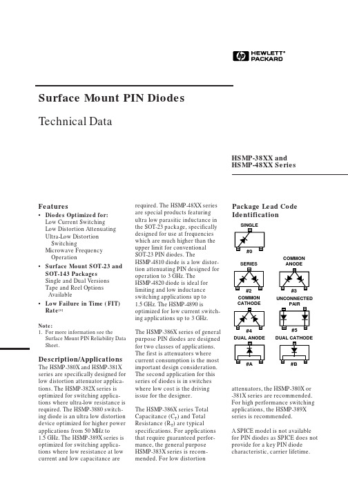
Surface Mount PIN Diodes Technical DataFeatures•Diodes Optimized for:Low Current SwitchingLow Distortion AttenuatingUltra-Low DistortionSwitchingMicrowave FrequencyOperation•Surface Mount SOT-23 and SOT-143 PackagesSingle and Dual VersionsTape and Reel OptionsAvailable•Low Failure in Time (FIT) Rate[1]Note:1.For more information see theSurface Mount PIN Reliability Data Sheet.HSMP-38XX andHSMP-48XX SeriesPackage Lead CodeIdentificationrequired. The HSMP-48XX seriesare special products featuringultra low parasitic inductance inthe SOT-23 package, specificallydesigned for use at frequencieswhich are much higher than theupper limit for conventionalSOT-23 PIN diodes. TheHSMP-4810 diode is a low distor-tion attenuating PIN designed foroperation to 3 GHz. TheHSMP-4820 diode is ideal forlimiting and low inductanceswitching applications up to1.5GHz. The HSMP-4890 isoptimized for low current switch-ing applications up to 3 GHz.The HSMP-386X series of generalpurpose PIN diodes are designedfor two classes of applications.The first is attenuators wherecurrent consumption is the mostimportant design consideration.The second application for thisseries of diodes is in switcheswhere low cost is the drivingissue for the designer.The HSMP-386X series TotalCapacitance (C T) and TotalResistance (R T) are typicalspecifications. For applicationsthat require guaranteed perfor-mance, the general purposeHSMP-383X series is recom-Description/Applications The HSMP-380X and HSMP-381X series are specifically designed for low distortion attenuator applica-tions. The HSMP-382X series is optimized for switching applica-tions where ultra-low resistance is required. The HSMP-3880 switch-ing diode is an ultra low distortion device optimized for higher power applications from 50 MHz to1.5GHz. The HSMP-389X series is optimized for switching applica-tions where low resistance at low attenuators, the HSMP-380X or -381X series are recommended. For high performance switching applications, the HSMP-389X series is recommended.A SPICE model is not available for PIN diodes as SPICE does not provide for a key PIN diode characteristic, carrier lifetime.2Absolute Maximum Ratings [1] T A = 25°CSymbol ParameterUnits Absolute Maximum I f Forward Current (1 ms Pulse)Amp 1P t Total Device Dissipation mW [2]250P iv Peak Inverse Voltage —Same as V BRT j Junction Temperature °C 150T STGStorage Temperature°C-65 to 150Notes:1.Operation in excess of any one of these conditions may result in permanent damage to this device.2.CW Power Dissipation at T LEAD = 25°C. Derate to zero at maximum rated temperature.PIN Switching DiodesElectrical Specifications T A = 25°CNearest Maximum Equivalent Minimum Maximum Maximum Shunt Mode Part Package Axial Lead Breakdown Series Total Harmonic Number Marking LeadPart No.Voltage Resistance Capacitance Distortion HSMP-Code [1]Code Configuration 5082-V BR (V)R S (Ω)C T (pF)Hmd (dBc)3820F00Single 3188500.6*0.8*—3822F22Series3823F33Common Anode 3824F44Common Cathode 3880S00Single—100 6.50.40–553890G00Single —1002.50.30**—3892G22Series3893G33Common Anode 3894G44Common Cathode 3895G55Unconnected PairTest ConditionsV R = V BR I F = 5 mA V R = 50 V 2 f o, Z o = 50 W Measure f = 100 MHz f = 1 MHz f o = 400 MHz I R ≤ 10 µA I F = 10 mA*V R = 20 V*P in = +30 dBm V R = 5 V**0 V biasPIN Attenuator DiodesElectrical Specifications T A = 25°C (Each Diode)NearestEquivalent Minimum Maximum Maximum Minimum Maximum Part Package Axial Lead Breakdown Series Total High Low Number Marking LeadPart No.Voltage Resistance Capacitance Resistance Resistance HSMP-Code [1]Code Configuration 5082-V BR (V)R S (Ω)C T (pF)R H (Ω)R L (Ω)3800D00Single 30801002.00.37100083802D22Series3804D44Common Cathode 3810E00Single 3081100 3.00.351500103812E22Series3813E33Common Anode 3814E44Common CathodeTest ConditionsV R = V BR I F = 100 mA V R = 50 V I F = 0.01 mA I F = 20 mA Measure f = 100 MHz f = 1 MHz f = 100 MHz f= 100 MHzI R ≤ 10 µA3PIN General Purpose Diodes, Electrical Specifications T A = 25°CNearestEquivalent Minimum Maximum Maximum Part Package Axial Lead Breakdown Series Total Number Marking Lead Part No.Voltage Resistance Capacitance HSMP-Code[1]Code Configuration5082-V BR (V)R S (Ω)C T (pF) 3830K00Single3077200 1.50.3 3832K22Series3833K33Common Anode3834K44Common CathodeTest Conditions V R = V BR I F = 100 mA V R = 50 VMeasure f = 100 MHz f = 1 MHzI R≤ 10 mAHigh Frequency (Low Inductance, 500 MHz – 3 GHz) PIN Diodes, Electrical Specifications T A = 25°CMinimum Maximum Typical Maximum TypicalBreak-Series Total Total Total Part Package down Resis-Capaci-Capaci-Induc-Number Marking Lead Config-Voltage tance tance tance tance Appli-HSMP-Code Code uration V BR (V)R S (Ω)C T (pF)C T (pF)L T (nH)cation 4810EB B Dual100 3.00.350.4 1.0Attenu-Cathode ator 4820FA A Dual Anode500.6*0.75* 1.0 1.0*Limiter 4890GA A Dual Anode100 2.5**0.330.375 1.0SwitchV R = V BR I F = 100 mA V R = 50 V V R = 50 V f = 500 MHz –Measure I F = 10 mA* f = 1 MHz f = 1 MHz 3 GHzI R≤ 10 µA I F = 5 mA**V R = 20 V*V R = 0 V V R = 20 V*PIN General Purpose Diodes, Typical Specifications T A = 25°CCode Minimum Typical Series Typical Total Part Number Marking Lead Breakdown Resistance Capacitance HSMP-Code[1]Code Configuration Voltage V BR (V)R S (Ω)C T (pF)3860L00Single50 3.0/1.5*0.203862L22Series3863L33Common Anode3864L44Common CathodeTest Conditions V R = V BR I F = 10 mA V R = 50 VMeasure f = 100 MHz f = 1 MHzI R≤ 10 µA*I F = 100 mATypical Parameters at T A = 25°CPart Number Series Resistance Carrier Lifetime Reverse Recovery Time Total Capacitance HSMP-R S (Ω)τ (ns)T rr (ns)C T (pF)380X5518005000.32 @ 50 V381X7515003000.27 @ 50 V382X 1.570*70.60 @ 20 V383X20500800.20 @ 50 V388X 3.825005500.30 @ 50 V389X 3.8200*–0.20 @ 5 V Test Conditions I F = 1 mA I F = 50 mA V R = 10 Vf = 100 MHz I R = 250 mA I F = 20 mAI F = 10 mA*I F = 10 mA*90% RecoveryI R = 6 mA*4Typical Parameters at T A = 25°C (unless otherwise noted), Single DiodeFigure 2. RF Capacitance vs. Reverse Bias, HSMP-3830 Series.0.150.300.250.200.350.400.45T O T A L C A P A C I T A N C E (p F )REVERSE VOLTAGE (V)Figure 1. RF Capacitance vs. Reverse Bias, HSMP-3810 Series.Figure 3. Resistance at 25°C vs. Forward Bias Current.0.150.300.250.200.35T O T A L C A P A C I T A N C E (p F )REVERSE VOLTAGE (V)R E S I S T A N C E (O H M S )I F – FORWARD BIAS CURRENT (mA)0.010.11101000.010.1110100R F R E S I S T A N C E (O H M S )I F – FORWARD BIAS CURRENT (mA)R F R E S I S T A N C E (O H M S )0.010.1110100I F – FORWARD BIAS CURRENT (mA)Figure 5. RF Resistance vs. Forward Bias Current for HSMP-3810/HSMP-4810.V R – REVERSE VOLTAGE (V)C A P A C I T A N C E (p F )Figure 6. Capacitance vs. Reverse Voltage.Figure 4. RF Resistance vs. Forward Bias Current for HSMP-3800.100010010DIODE RF RESISTANCE (OHMS)Figure 7. 2nd Harmonic Input Intercept Point vs. Diode RFResistance for Attenuator Diodes.I N P U T I N T E R C E P T P O I N T (d B m )12011511010510095908511030I F – FORWARD BIAS CURRENT (mA)Figure 8. 2nd Harmonic Input Intercept Point vs. Forward Bias Current for Switch Diodes.I N P U T I N T E R C E P T P O I N T (d B m )FORWARD CURRENT (mA)Figure 9. Reverse Recovery Time vs. Forward Current for Various Reverse Voltages. HSMP-3820 Series.T r r – R E V E R S E R E C O V E R Y T I M E (n s )110100102030V R = 2V V R = 5VV R = 10VHSMP-382X5Typical Parameters (continued)100010010102030T r r - R E V E R S E R E C O V E R Y T I M E (n S )FORWARD CURRENT (mA)Figure 10. Reverse Recovery Time vs. Forward Current for Various Reverse Voltage. HSMP-3830 Series.HSMP-3830V R = 5VV R = 10V V R = 20VR E V E R S E R E C O V E R Y T I M E (n S )FORWARD CURRENT (mA)Figure 11. Typical Reverse Recovery Time vs. Reverse Voltage. HSMP-3880 Series.1020152530T R R - R E V E R S E R E C O V E R Y T I M E (n S )FORWARD CURRENT (mA)Figure 12. Typical Reverse Recovery Time vs. Reverse Voltage. HSMP-3890 Series.1001010.10.01I F – F O R W A R D C U R R E N T (m A )I F – F O R W A R D C U R R E N T (m A )V F – FORWARD VOLTAGE (mA)Figure 14. Forward Current vs. Forward Voltage. HSMP-3810 and HSMP-4810 Series.V F – FORWARD VOLTAGE (mA)Figure 15. Forward Current vs. Forward Voltage. HSMP-3820 and HSMP-4820 Series.1001010.10.01I F – F O R W A R D C U R R E N T (m A )V F – FORWARD VOLTAGE (mA)Figure 16. Forward Current vs.Forward Voltage. HSMP-3830 Series.00.20.40.60.81.01.2I F – F O R W A R D C U R R E N T (m A )V F – FORWARD CURRENT (mA)Figure 17. Forward Current vs.Forward Voltage. HSMP-3880 Series.0.20.40.60.81.01.2V F – FORWARD VOLTAGE (mA)Figure 18. Forward Current vs. Forward Voltage. HSMP-3890 and HSMP-4890 Series.6Typical Parameters (continued)Figure 19. Typical RF Resistance vs. Forward Bias Current for HSMP-3860.Figure 20. Forward Current vs. Forward Voltage for HSMP-3860.Figure 21. Typical Capacitance vs. Reverse Bias for HSMP-3860.10001R E S I S T A N C E (O HM S )BIAS CURRENT (mA)10100I F – F O R W A R D C U R R E N T (m A )V F – FORWARD VOLTAGE (V)0200.515C T – C A P A C I T A N C E (p F )V R – REVERSE VOLTAGE (V)0.20.41050.10.30.12 pF** Measured at -20 V C p 0.08 pFR j = 12ΩI 0.9C T = C P + C jI = Forward Bias Current in mAEquivalent Circuit ModelHSMS-38607Typical Applications for Multiple Diode ProductsRF COMMONRF 1RF 1Figure 24. Switch Using Both Positive and Negative Bias Current.Figure 25. Very High Isolation SPDT Switch, Dual Bias.8Typical Applications for Multiple Diode Products (continued)INPUT RF IN/OUTFigure 26. Four Diode π Attenuator.Figure 27. High Isolation SPST Switch (Repeat Cells as Required).VOLTAGEBIASFigure 28. Power Limiter Using HSMP-3822Diode Pair.9Typical Applications for HSMP-48XX Low Inductance SeriesFigure 29. Internal Connections.HSMP-4820 & HSMP-4890HSMP-48100.5 nH*0.8pF TYPICAL FOR HSMP-3820Figure 30. Equivalent Circuit.*0.8 pF TYPICAL FOR HSMP-3820Figure 32. Equivalent Circuit.Figure 31. Circuit Layout.Microstrip SeriesConnection for HSMP-48XX SeriesIn order to take full advantage of the low inductance of the HSMP-48XX series when using them in series application,both lead 1 and lead 2 should beconnected together, as shown above.10Microstrip Shunt Connections for HSMP-48XX SeriesIn the diagram above, the center conductor of themicrostrip line is interrupted and leads 1 and 2 of theHSMP-38XX series diode are placed across the resulting gap. This forces the 0.5 nH lead inductance of leads 1 and 2 to appear as part of a low pass filter, reducing the shunt parasitic inductance andincreasing the maximumavailable attenuation. The 0.3 nH of shunt inductance external to the diode is created by the via holes, and is a good estimate for 0.032" thick material.Co-Planar Waveguide Shunt Connection for HSMP-48XX SeriesCo-Planar waveguide, with ground on the top side of the printed circuit board, is shownin the diagram above. Since it eliminates the need for via holes to ground, it offers lower shunt parasitic inductance and higher maximum attenuation whencompared to a microstrip circuit.GROUND BY TWOVIA HOLES*0.8 pF TYPICAL FOR HSMP-4820Figure 34. Equivalent Circuit.Figure 33. Circuit Layout.*0.8 pF TYPICAL FOR HSMP-4820Figure 36. Equivalent Circuit.Figure 35. Circuit Layout.11Package DimensionsOutline 23 (SOT-23)PC Board FootprintsSOT-23Package CharacteristicsLead Material......................................................................................Alloy 42Lead Finish............................................................................Tin-Lead 85-15%Maximum Soldering Temperature..............................260°C for 5 seconds Minimum Lead Strength..........................................................2 pounds pull Typical Package Inductance ..................................................................2 nH Typical Package Capacitance ..............................0.08 pF (opposite leads)SOT-143Outline 143 (SOT-143)SIDE VIEWEND VIEWDIMENSIONS ARE IN MILLIMETERS (INCHES)DIMENSIONS ARE IN MILLIMETERS (INCHES)PACKAGE MARKING/go/rfFor technical assistance or the location of your nearest Hewlett-Packard salesoffice, distributor or representative call:Americas/Canada: 1-800-235-0312 or 408-654-8675Far East/Australasia: Call your local HP sales office.Japan: (81 3) 3335-8152Europe: Call your local HP sales office.Data subject to change.Copyright © 1999 Hewlett-Packard Co.Obsoletes 5968-3435E5968-5439E (6/99)Profile Option Descriptions-BLK = Bulk-TR1 = 3K pc. Tape and Reel, Device Orientation; See Figures 37 and 38-TR2 = 10K pc. Tape and Reel, Device Orientation; See Figures 37 and 38Tape and Reeling conforms to Electronic Industries RS-481, “Taping of Surface Mounted Components for Automated Placement.”Ordering InformationSpecify part number followed by option under. For example:H SMP -38XX -XXXBulk or Tape and Reel OptionPart NumberSurface Mount PIN Diode Hewlett-PackardUSER FEEDEND VIEWTOP VIEW Figure 37. Options -TR1, -TR2 for SOT-23 Packages.Figure 38. Options -TR1, -TR2 for SOT-143 Packages.END VIEWTOP VIEW。
BWT-3800_V16A.008_eNB_基带板上电过程获取时钟状态信息测试规范V1.0

BWT-3800-eNB基带板上电过程获取时钟状态信息测试规范(仅供内部使用)修订记录目录1 概述 (4)2 常用术语、定义和缩写 (4)3 测试设备及工具 (4)4 测试内容 (5)4.1 第一代BPB获取时钟状态测试 (5)4.1.1 BPB板获取锁定的时钟状态测试 (5)BPB板获取锁定的时钟状态测试 (5)4.1.2 BPB板获取失锁的时钟状态测试 (6)BPB板获取失锁的时钟状态测试 (6)4.2 第二代BPB获取时钟状态测试 (7)4.2.1 GPS不在位情况下,BPB板获取时钟状态流程测试(一) (7)4.2.2 GPS不在位情况下,BPB板获取时钟状态流程测试(二) (7)4.2.3 GPS时钟锁定情况下,BPB板获取时钟状态流程测试(一) (8)4.2.4 GPS时钟锁定情况下,BPB板获取时钟状态流程测试(二) (8)4.2.5 GPS时钟失锁情况下,BPB板获取时钟状态流程测试(一) (9)4.2.6 GPS时钟失锁情况下,BPB板获取时钟状态流程测试(二) (10)1概述本《BWT-3800-eNB功能特性_基带板上电过程获取时钟状态信息》测试规程用于规范LTE带板上电过程获取时钟状态信息系统测试执行中的操作过程和提供具体的测试用数据。
在本测试规程中以测试任务为单位描述针对各条需求或待测特性的测试过程,测试任务的安排顺序也为执行顺序。
2常用术语、定义和缩写3测试设备及工具测试环境框图见图3.1.。
图3.1多天线功能测试环境图本测试环境所需软件清单见表3.1:表3.1本测试环境所需硬件清单见表3.1.2:表 3.1.24测试内容4.1 第一代BPB获取时钟状态测试4.1.1BPB板获取锁定的时钟状态测试4.1.2BPB板获取失锁的时钟状态测试4.2第二代BPB获取时钟状态测试4.2.1 GPS不在位情况下,BPB板获取时钟状态流程测试(一)4.2.2 GPS不在位情况下,BPB板获取时钟状态流程测试(二)4.2.3 GPS时钟锁定情况下,BPB板获取时钟状态流程测试(一)4.2.4 GPS时钟锁定情况下,BPB板获取时钟状态流程测试(二)4.2.5 GPS时钟失锁情况下,BPB板获取时钟状态流程测试(一)4.2.6 GPS时钟失锁情况下,BPB板获取时钟状态流程测试(二)。
雷赛3800卡运动控制卡说明书

雷赛3800卡运动控制卡说明书雷赛DMC3800八轴高性能点位卡特点概述:八轴伺服/步进电机控制;八轴增量式编码器。
优秀的PVT规划;高速位置锁存\比较及触发。
丰富的IO控制与延时翻转;优秀的T型、S型速度曲线。
在线变速、在线变位置;简单直线插补、圆弧插补;总线扩展。
功能特性:DMC3000系列高级点位控制卡,是雷赛智能推出的功能丰富、性能优良的高性能脉冲型点位控制卡。
可控制1-8轴伺服或步进电机,每轴最高频率4MHz,支持S型曲线,在线变速/变位置,PVT,简单直线插补,圆弧插补,高速位置锁存,高速位置比较输出,编码器反馈等高级点位功能。
位置指令可用单脉冲(脉冲+方向)或双脉冲(CW脉冲+CCW脉冲)方式输出,可以是单端或者差分式,适合控制各种接口的伺服、步进及其组合。
另外控制卡本身自带多路通用I/O口,能满足大部分应用场合的I/O需求。
同时,支持CAN 总线I/O扩展,通过外接总线模块也可满足大批量I/O点数的场合,方便控制系统的I/O扩展与升级。
该系列产品配备有WINDOWS系统下的动态链接库,方便编写自己的应用软件,还提供了功能丰富、界面友好的MOTION3000调试软件,无需编程即可测试控制卡接口及电机驱动系统。
卓越的运动控制性能优秀的PVT规划轻松调用内置PVT函数,您只需要输入位置、时间或位置、速度、时间参数就能实现复杂的轨迹规划,有效缩短开发时间,让应用开发变得更简单。
优秀的速度控制初速度、加速时间和停止速度、减速时间可独立设置,对称和非对称的T型、S型速度控制功能,加减速快、平顺稳定。
在线变速、在线变位置速度模式下,T型/S型在线变速(同向/反向);位置模式下,在线变速/变位置,让速度控制、位置控制更加智能、快捷。
直线插补DMC3000系列运动控制卡支持简单直线插补功能,插补速度快,精度高,最大位置误差在1个脉冲内。
圆弧插补DMC3000系列运动控制卡支持简单圆弧插补功能,插补速度快,精度高,最大位置误差在1个脉冲内。
Honeywell 3800 Linear Series 快速说明书

3800 Linear Series 快速入门指南注: 有关清洁设备的信息,请参阅用户指南。
入门连接扫描器之前请关闭计算机电源,然后在扫描器完全连接后打开计算机电源。
USB 连接1键盘口连接连接串口 (RS-232)23读取技巧取景器发出的红色瞄准光束应位于条码正中。
将扫描器对准条码,按动触发器,使瞄准光束位于条码的正中。
扫描器越接近条码,瞄准光束越小;扫描器越远离条码,瞄准光束越大。
如果条码较小,应使扫描器靠近条码;如果条码较大,扫描器应离条码远一点,这样更容易正确读取条码。
如果条码反射度高(例如,镀膜的),您可能需要以某一角度倾斜扫描器,以便扫描条码。
4若要使用支持 PDF 码的 3800 设备读取 PDF417 条码,请保持触发器按下并上下移动扫描器,以便瞄准线可从条码的顶部扫描到底部,再从底部扫描回顶部。
这样可确保完整扫描条码。
附注:此方法只适用于支持 PDF 码的 3800/3800g设备。
标准产品默认设置以下条码重置所有标准产品默认设置。
标准产品默认设置5接口请扫描符合您所使用的 PC或接口的条码。
AT/PS2 键盘口(默认设置)RS-232USB 键盘 (PC)仿真外接键盘日本 DOS/V6键盘的国家/地区设置扫描下面的键盘的国家/地区设置条码,然后扫描第 10 页中的数字条码,接着扫描保存条码,以便对您所在的国家/地区的键盘进行设置。
原则上,在除美国以外的国家/地区,扫描器不支持以下字符:@ | $ # { } [ ] = /‘ \ < > ~.附注:有关国家/地区代码的完整列表,请参见我们的网站/aidc 提供的针对您所购买产品的用户指南。
国家/地区代码扫描国家/地区代码扫描比利时1意大利5丹麦8挪威9芬兰2西班牙10法国3瑞士6德国/奥地利4美国(默认)英国7键盘的国家/地区设置保存7触发器以下条码允许您在“手动触发”模式(需要按住触发器进行读取)、“自动触发”模式(光束始终打开)或“感应”模式(读取器在“检测到”条码后激活)下使用读取器。
得普声rev3800说明书
得普声rev3800说明书第一章:产品介绍普声REV3800是一款高性能的家庭音响系统,由普声公司设计和制造。
该音响系统拥有出色的音质和功能,适用于家庭娱乐和音乐欣赏。
第二章:外部设计REV3800采用了现代化的外观设计,外壳采用高质量的铝制材料,给人一种坚固耐用的感觉。
整机尺寸为400mm x 200mm x 300mm,重量为10kg。
第三章:功能特点1.多功能输入接口:REV3800配备了多种输入接口,包括蓝牙、USB、有线音频和光纤输入接口,可以连接多种音频设备,如手机、电脑、电视等。
2.高品质音质:该音响系统采用了先进的数字音频处理技术,可以提供高保真和清晰的音质。
内置放大器的功率为50Wx2,可以满足大部分家庭的听音需求。
3.无线蓝牙连接:REV3800支持蓝牙无线连接,可以方便地连接手机和其他蓝牙设备,播放音乐和其他媒体内容。
4.人性化操作界面:该音响系统配备了易于使用的触摸按钮和显示屏,可以方便地进行音量控制、输入切换和设置调整等操作。
5.重低音增强功能:REV3800内置了重低音增强器,可以通过调整控制面板上的低音控制开关来增强低音效果,让音乐更加震撼。
第四章:使用说明1.连接电源:首先将音响系统与电源适配器连接,并将电源适配器插入电源插座。
2.连接音频设备:根据需要选择合适的音频输入接口,通过相应的音频线缆将音频设备连接到REV3800。
3.打开音响系统:按下电源按钮,系统将进入待机状态,并显示当前输入源。
4.调整音量:可以使用音量按钮或触摸屏上的音量调节栏来调整音量大小。
5.切换输入源:使用输入源选择按钮或触摸屏上的输入源切换栏,可以切换不同的音频输入源。
6.蓝牙连接:打开蓝牙功能并到REV3800,然后选择连接即可进行蓝牙音频播放。
7.重低音增强:通过控制面板上的低音控制开关,可以增强低音效果,满足个人音响需求。
第五章:维护和保养1.清洁:定期使用柔软的布轻轻擦拭音响系统的外壳和显示屏,不要使用化学或腐蚀性清洁剂。
GC-瓦里安3800说明书

自动启动开关 ............... ............................. ............................. ...................64 进样器装配图及内衬....................................................................... ...............64 色谱柱安装.............................................................................. .....................65 1041 进样器操作............................................................................................69 1041进样器测试......................................................................... ........... .......70 1061闪蒸进样器...................................................................... ........... ........... .................72 自动启动开关 ............................. .................................................................72 进样器及内衬............................................................................. .................72 色谱柱安装............................ .......................................................................73 1061进样器操作.......................... ..................................................................76 1061进样器测试................................................ .......... .................................78
采煤机型号及主要参数
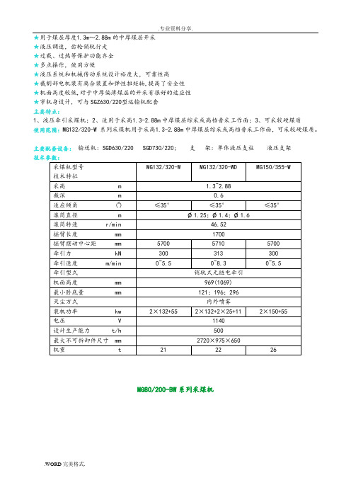
★用于煤层厚度1.3m~2.88m的中厚煤层开采★液压调速,齿轮销轨行走★过载、过热等保护功能齐全★多点操作,使用方便★液压系统和机械传动系统设计裕度大,可靠性高★截割部电机装有离合装置和弹性扭矩轴,提高了安全性★机面高度较低,对于中厚偏薄煤层的开采有很好的适应性★窄机身设计,可与SGZ630/220型运输机配套主要特点:1、液压牵引采煤机;2、适用于采高1.3-2.88m中厚煤层综采或高档普采工作面;3、可采较硬煤质使用范围:MG132/320-W 系列采煤机用于采高1.3-2.88m中厚煤层综采或高档普采工作面,可采较硬煤质。
主要配套设备:输送机: SGD630/220 SGD730/220; 支架: 单体液压支柱液压支架技术参数:MG80/200-BW系列采煤机该机功率较大,机身短、窄、薄、对于薄煤层适应性大,是目前本公司及国内无链牵引最矮的机型,也是目前国内薄煤层多电机横向布置采煤机的最矮、最小机型。
采用多电机横向布置,抽屉式安装,机械传动系统各自独立,马达和油缸外置便于维护、检修;机身主体为一个箱体,无对接面,避免了以往采煤机对接螺栓松动问题。
因此故障点,漏油点少,故障率低。
本机无底托架,从而加大了机身下面的过煤高度。
液压锁和油缸进行分体设计,便于故障查找,维护和更换。
主泵和马达富裕系数较大,液压外配套件选用国内厂家的名牌产品,可靠性高。
牵引末级采用两级双浮动行星传动。
结构紧凑、体积小。
采用弯摇臂设计,加大过煤空间,提高装煤效果。
行走箱内的行走轮,采用了特殊滑动轴承,提高了可靠性。
两截割电机设有机械离合装置,检修安全方便。
将管路尽可能布置在机壳内部,使胶管的防护性好,整机无护罩。
导向滑靴采用分体式,便于更换。
电气系统设有过热、过流保护装置,保护齐全。
该机中间和两端都设有手把和按钮,可实现多点控制便于操作。
MG132/320-W系列采煤机本采煤机采用多部电机横向布置的结构方式,各部件纵向之间没有直接的动力传动,各部件的机械传动分别独立,改善了受力条件,提高了传动件的运动精度,并且简单可靠,大大提高了机械传动效率,降低了机体的发热程度,从根本上克服了电机纵向布置传动形式存在的漏油、噪声大等诸多不足。
FortiGate 3800D系列产品说明说明书

FortiGate ®3800D SeriesFortiGate 3800D/-DC, 3810D/-DC and 3815D/-DCThe Fortinet Enterprise Firewall Solution delivers end-to-end network security with one platform, one network security operating system and unified policy management with a single pane of glass — for the industry’s best protection against the most advanced security threats and targeted attacks .Powered by SPU§Custom SPU processors deliver the power you need to detect malicious content at multi-Gigabit speeds§Other security technologies cannot protect against today’s wide range of content- and connection-based threats because they rely on general-purpose CPUs, causing a dangerous performance gap§SPU processors provide the performance needed to block emerging threats, meet rigorous third-party certifications, and ensure that your network security solution does not become a network bottleneckNetwork ProcessorFortinet’s new, breakthrough SPU NP6 network processor works inline with FortiOS functions delivering:§Superior firewall performance for IPv4/IPv6, SCTP and multicast traffic with ultra-low latency down to 2 microseconds §VPN, CAPWAP and IP tunnel acceleration§Anomaly-based intrusion prevention, checksum offload and packet defragmentation§Traffic shaping and priority queuingContent ProcessorThe SPU CP8 content processor works outside of the direct flow of traffic, providing high-speed cryptography and content inspection services including:§Signature-based content inspection acceleration §Encryption and decryption offloadingInterfaces1. USB Management Port2. USB Port3. Console Port4. 2x GE RJ45 Management Ports5. 6x 100 GE CFP2 SlotsFortiGate 3810D/-DC FortiGate 3815D/-DC Interfaces1. Console Port2. USB Port3. 2x GE RJ45 Management Ports4. 4x 100 GE CFP2 Slots5. 10x 10 GE SFP+ SlotsFortiGate 3800D/-DCInterfaces1. Console Port2. USB Port3. 2x GE RJ45 Management Ports4. 4x 100 GE CFP2 Slots5. 4x 40 GE QSFP+ Slots6. 8x 10 GE SFP+/GE SFP Slots3SERVICESFortiGuard ™ Security ServicesFortiGuard Labs offers real-time intelligence on the threat landscape, delivering comprehensive security updates across the full range of Fortinet’s solutions. Comprised of security threat researchers, engineers, and forensic specialists, the team collaborates with the world’s leading threat monitoring organizations, other network and security vendors, as well as law enforcement agencies:§Real-time Updates — 24x7x365 Global Operations research security intelligence, distributed via Fortinet Distributed Network to all Fortinet platforms.§Security Research — FortiGuard Labs have discovered over 170 unique zero-day vulnerabilities to date, totaling millions of automated signature updates monthly.§Validated Security Intelligence — Based on FortiGuard intelligence, Fortinet’s network security platform is tested and validated by the world’s leading third-party testing labs and customers globally.FortiCare ™ Support ServicesOur FortiCare customer support team provides global technical support for all Fortinet products. With support staff in the Americas, Europe, Middle East and Asia, FortiCare offers services to meet the needs of enterprises of all sizes:§Enhanced Support — For customers who need support during local business hours only.§Comprehensive Support — For customers who need around-the-clock mission critical support, including advanced exchange hardware replacement.§Advanced Services — For global or regional customers who need an assigned Technical Account Manager, enhanced service level agreements, extended software support, priority escalation, on-site visits and more.§Professional Services — For customers with more complex security implementations that require architecture and design services, implementation and deployment services, operational services and more.For more information, please refer to the FortiOS data sheet available at FortiOSControl all the security and networking capabilities across the entire FortiGate platform with one intuitive operating system. Reduce operating expenses and save time with a truly consolidated next generation security platform.§ A truly consolidated platform with one OS for all security and networking services for all FortiGate platforms.§Industry-leading protection: NSS Labs Recommended, VB100, AV Comparatives and ICSA validated security and performance. §Control thousands of applications, block the latest exploits, and filter web traffic based on millions of real-time URL ratings. §Detect, contain and block advanced attacks automatically in minutes with integrated advanced threat protection framework. §Solve your networking needs with extensive routing, switching, WiFi, LAN and WAN capabilities.§Activate all the SPU-boosted capabilities you need on the fastest firewall platform available.Enterprise BundleFortiGuard Labs delivers a number of security intelligence services to augment the FortiGate firewall platform. You can easily optimize the protection capabilities of your FortiGate with the FortiGuard Enterprise Bundle. This bundle contains the full set of FortiGuard security services plus FortiCare service and support offering the most flexibility and broadest range of protection all in one package.GLOBAL HEADQUARTERS Fortinet Inc.899 KIFER ROAD Sunnyvale, CA 94086United StatesTel: +/salesEMEA SALES OFFICE 905 rue Albert Einstein 06560 Valbonne FranceTel: +33.4.8987.0500APAC SALES OFFICE 300 Beach Road 20-01The Concourse Singapore 199555Tel: +65.6395.2788LATIN AMERICA SALES OFFICE Sawgrass Lakes Center13450 W. Sunrise Blvd., Suite 430 Sunrise, FL 33323United StatesTel: +1.954.368.9990Copyright© 2017 Fortinet, Inc. All rights reserved. Fortinet®, FortiGate®, FortiCare® and FortiGuard®, and certain other marks are registered trademarks of Fortinet, Inc., in the U.S. and other jurisdictions, and other Fortinet names herein may also be registered and/or common law trademarks of Fortinet. All other product or company names may be trademarks of their respective owners. Performance and other metrics contained herein were attained in internal lab tests under ideal conditions, and actual performance and other results may vary. Network variables, different network environments and other conditions may affect performance results. Nothing herein represents any binding commitment by Fortinet, and Fortinet disclaims all warranties, whether express or implied, except to the extent Fortinet enters a binding written contract, signed by Fortinet’s General Counsel, with a purchaser that expressly warrants that the identified product will perform according to certain expressly-identified performance metrics and, in such event, only the specific performance metrics expressly identified in such binding written contract shall be binding on Fortinet. For absolute clarity, any such warranty will be limited to performance in the same ideal conditions as in Fortinet’s internal lab tests. In no event does Fortinet make any commitment related to future deliverables, features or development, and circumstances may change such that any forward-looking statements herein are not accurate. Fortinet disclaims in full any covenants, representations, and guarantees pursuant hereto, whether express or implied. Fortinet reserves the right to change, modify, transfer, or otherwise revise this publication without notice, and the most current version of the publication shall be applicable.FST -PR D-DS-GT38K FG-3800D-DAT -R6-201701FortiGate3800D SeriesORDER INFORMATION100 GE CFP2 Transceivers, Long Range FG-TRAN-CFP2-LR4100 GE CFP2 transceivers, long range, over single mode fiber, for all systems with CFP2 slots.10 GE SFP+ Transceiver Module, Short Range FG-TRAN-SFP+SR 10 GE SFP+ transceiver module, short range for all systems with SFP+ and SFP/SFP+ slots.10 GE SFP+ Transceiver Module, Long Range FG-TRAN-SFP+LR 10 GE SFP+ transceiver module, long range for all systems with SFP+ and SFP/SFP+ slots.1 GE SFP LX Transceiver Module FG-TRAN-LX 1 GE SFP LX transceiver module for all systems with SFP and SFP/SFP+ slots.1 GE SFP RJ45 Transceiver Module FG-TRAN-GC 1 GE SFP RJ45 transceiver module for all systems with SFP and SFP/SFP+ slots.1 GE SFP SX Transceiver Module FG-TRAN-SX 1 GE SFP SX transceiver module for all systems with SFP and SFP/SFP+ slots.100 GE SR10 to 10x 10 GE Fan Out Cable FG-CABLE-SR10-SFP+100 GE SR10 to 10x 10 GE SFP+ 1M fan out cable.AC Power Supply SP-FG3800D-PS AC power supply for FG-3700D, FG-3700D-NEBS, FG-3700DX, FG-3810D and FG-3815D.DC Power Supply SP-FG3800D-DC-PS DC power supply for FG-3700D-DC, FG-3700D-DC-NEBS, FG-3810D-DC, FG-3815D-DC.Rack Mount Sliding RailsSP-FG3040B-RAILRack mount sliding rails for FG-1000C/-DC, FG-1200D, FG-1500D/DC, FG-3040B/-DC, FG-3140B/-DC, FG-3240C/-DC, FG-3000D/-DC, FG-3100D/-DC, FG-3200D/-DC, FG-3700D/-DC, FG-3700DX, FG-3810D/-DC and FG-3950B/-D.。
NETGEAR AC750 WiFi范围扩展器模型EX3800 快速入门指南说明书
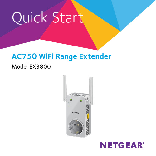
AC750 WiFi Range Extender Model EX3800WiFi Range ExtenderBoosts the range of your existing WiFi and creates a stronger signal areas Existing WiFi Sometimes your router does not provide the WiFi coverage that you needMeet Your ExtenderBefore you install your extender, familiarize yourself with its LEDs, buttons, and port.Front PanelRouter DeviceSide Panelsregion)LED DescriptionsRouter Link LED This LED indicates the connection between the extender andthe router or access point.Solid green. Best connection.Solid ambe r. Good connection.Solid red. Poor connection.Off. No connection.Device Link LED This LED indicates the connection between the extender anda computer or WiFi device.Solid green. Best connection.Solid amber. Good connection.Solid red. Poor connection.Off. No connection.Power LED Solid amber. The extender is booting.Solid green. The extender is powered on.Off. The extender is powered off.WPS LED Solid green. WiFi security is enabled (WPA or WPA2).Blinking green. A WPS connection is being established.Off. WiFi security is not enabled.Note: If the Router Link LED or Device Link LED is amber or red, see Find the Best Location on page 11.Use the Extender in Extender ModePlace the extender, apply power, and connect it to your WiFi network. Place the Extender and Apply Power1. Place your extender in the same room as your WiFi router.Proximity to the WiFi router is required only during the initial setupprocess.2. Plug the extender into an electrical outlet.Wait for the Power LED to light green. If the Power LED does not light, press the Power On/Off button on the extender.Connect to an Existing WiFi NetworkTo extend the range of your WiFi network, you must connect the extender to your existing WiFi network. You can do this in one of two ways:• Connect with WPS. For more information, see Connect with WPS on page 7.• Connect with web browser setup. For more information, see Connect with Web Browser Setup on page 9.Connect with WPSWi-Fi Protected Setup (WPS) lets you join a secure WiFi network without typing the network name and password.Note: WPS does not support WEP network security. If you are using WEP security, follow the instructions in Connect with Web Browser Setup on page 9.1. Press the WPS button on the side panel of the extender.The WPS LED blinks.2. Within two minutes, press the WPS button on your router or accesspoint.The WPS LED on the extender lights solid green, the Router Link LED lights, and the extender connects to your existing WiFi network.If the Router Link LED does not light, try again. If it still does not light, see Connect with Web Browser Setup on page 9.3. If your WiFi router supports the 5 GHz band, repeat Steps 1 and 2 toconnect the extender to the 5 GHz band.4. Find the new extended WiFi network name on your computer or WiFidevice.The extender creates two new extended WiFi networks. Theextender’s new WiFi network names are based on your existing WiFi network name, with _2GEXT and _5GEXT at the end of the name.For example:• Existing WiFi network name. MyNetworkName• New extended WiFi network names. MyNetworkName_2GEXT and MyNetworkName_5GEXT5. Connect your computer or WiFi devices to the new extended WiFinetwork.Use the same WiFi password that you use for your WiFi router.6. Unplug the extender and move it to a new location closer to the areawith a poor WiFi signal.The location that you choose must be within the range of yourexisting WiFi router network.7. Plug the extender into an electrical outlet.Wait for the Power LED to light green. If the Power LED does not light, press the Power On/Off button on the extender.8. Use the Router Link LED on the front panel to help you choose a spotwhere the extender-to-router connection is optimal.Connect with Web Browser Setup1. Use a WiFi network manager on a computer or WiFi device to find andconnect to the NETGEAR_EXT (SSID) WiFi network.After the connection with the computer or WiFi device is established, the Device Link LED lights.2. Launch a web browser.3. Enter in the address field of the browser.The New Extender Setup screen displays.4. Click the NEW EXTENDER SETUP button.The Extender Setup screen displays.5. Complete the fields on the Extender Setup screen and click the NEXTbutton.6. Click the WIFI RANGE EXTENDER button.The extender searches for WiFi networks in your area and displays a list.7. Select a WiFi network to extend and click the NEXT button.If you do not want to extend both WiFi bands, clear the 2.4GHz WiFi Networks or the 5GHz WiFi Networks check box.8. In the Password (network key) field, type the existing WiFi networkpassword (also called passphrase or security key) and click the NEXT button.9. Set the network name (SSID) and password for your extender andclick the NEXT button.10. Use a WiFi network manager on the computer or WiFi device toconnect to the new extended WiFi network.Repeat this step for all of your computers and WiFi devices.11. Click the Continue button.A message displays confirming that the extender is connected to thenew extended WiFi network.12. Click the Next button.The Status screen displays.13. Unplug the extender and move it to a new location closer to the areawith a poor WiFi signal.The location that you choose must be within the range of yourexisting WiFi router network.14. Plug the extender into an electrical outlet.Wait for the Power LED to light green. If the Power LED does not light, press the Power On/Off button on the extender.Use the Router Link LED to help you choose a spot where theextender-to-router connection is optimal.Find the Best LocationIf the WiFi signal is weak, the first time you join the extender network, the Router Link LED or Device Link LED is amber or red. If this happens, adjust the position of the extender.• If the Router Link LED is amber or red, move the extender closer to the router.• If the Device Link LED is amber or red, move the computer or WiFi device closer to the extender.Use the Extender in Access Point ModeYou can use the extender as a WiFi access point, which creates a new WiFi hotspot using a wired Ethernet connection.1. Plug the extender into an electrical outlet.Wait for the Power LED to light green. If the Power LED does not light, press the Power On/Off button.2. Use an Ethernet cable to connect the Ethernet port on the extenderto a router Ethernet LAN port or a remote Ethernet LAN jack with LAN access.The extender joins the LAN and creates a WiFi hotspot.3. Use a WiFi network manager on a computer or WiFi device to find andconnect to the NETGEAR_EXT (SSID) WiFi network.After the connection with the computer or WiFi device is established, the Device Link LED lights.4. Launch a web browser and enter in the addressfield.The New Extender Setup screen displays.5. Click the NEW EXTENDER SETUP button.The Extender Setup screen displays.6. Complete the fields on the Extender Setup screen and click the NEXTbutton.7. Click the ACCESS POINT button.The extender checks for an Internet connection.8. Set the network name (SSID), security option, and password for eachaccess point in the network, and click the NEXT button.Your settings are applied and the extender is ready to be used as an access point.9. Use a WiFi network manager on the computer or WiFi device toconnect to the new access point WiFi network.Connect an Ethernet-Enabled Device After the extender is connected to your existing WiFi network, you can connect a wired device to the extender using an Ethernet cable. ThatExtenderWiFi routerBlu-ray playerLog In to Access Extender SettingsAfter installation, you can log in to the extender to view or change the extender’s settings.1. Use a WiFi network manager on a computer or WiFi device to find andconnect to the new extended WiFi network.After the connection with the computer or WiFi device is established, the Device Link LED lights.2. Launch a web browser.3. Enter in the address field of the browser.A login screen displays.4. Type your email and password and click the LOG IN button.The Status screen displays.5. Make any needed changes.Frequently Asked QuestionsYou can find more information about your extender in the user manual, which is available at .The web browser setup guide keeps asking me for my network password (passphrase) or security key, and I am sure that I entered the correct password. What can I do?The extender is probably placed at the borderline of the range covered by the router or access point. For more information, see Place the Extender and Apply Power on page 6.If you are using WEP security, make sure that you are typing the network password in the correct field.Can I set up the extender in extender mode if I connect it to the router or access point with an Ethernet cable?No. The extender is designed to connect wirelessly to the router or access point if it is in extender mode. If the extender is in access point mode, you can connect it to the router or access point with an Ethernet connection. For more information about access point mode, see Use the Extender in Access Point Mode on page 12.I forgot my login email address and password. What can I do?On the login screen, click the Username & Password Help link to answer the security questions that you set up during the initial setup.If you forgot the answers to your security questions, do the following to set up your login credentials again:1. Restore the extender to its factory default settings.2. Launch a web browser.3. Enter in the address field of the browser.The New Extender Setup screen displays.4. Click the NEW EXTENDER SETUP button.The Extender Setup screen displays.5. Complete the fields on the Extender Setup screen.How do I restore the extender to its factory default settings?1. Use a sharp object such as a pen or paper clip to press and hold theFactory Reset button on the extender for at least five seconds until the Power LED lights amber.2. Release the Factory Reset button and wait for the extender toreboot.The extender resets and returns to the factory default settings.I enabled a wireless MAC filter, wireless access control, or access control list (ACL) on my router. What should I do when installing the extender?When the WiFi device connects through the extender to your router, the MAC address of the WiFi device shown on the router is translated to another MAC address. If your router’s MAC filter, wireless access control, or ACL is enabled, the WiFi device connects to the extender but cannot get an IP address from the extender and cannot access the Internet.To allow the WiFi device to receive an IP address from the extender and access the Internet, you must provide the translated MAC address to the router.1. Log in to your router and disable the MAC filter, wireless accesscontrol, or ACL.For more information about how to disable your router’s MAC filter, wireless access control, or ACL, see your router’s documentation. 2. Power on the extender and connect all of your WiFi devices to theextender network.3. Make sure that the Router Link LED remains lit.4. Log in to your extender:a. Launch a web browser.b. Enter in the address field of the browser.A login screen displays.c. Type your email address and password and click the LOG INbutton.The Status screen displays.5. Select Settings > WiFi Settings.6. Scroll down and select Connected Devices.The Connected Devices section displays the MAC addresses andvirtual MAC addresses for computers and WiFi devices that areconnected to the extender network.7. On the router, add all of the virtual MAC addresses from yourextender to your router’s MAC filter table.8. Enable the router’s MAC filter, wireless access control, or ACL.I am connected to NETGEAR_EXT and launched a browser, but I can’t see the web browser setup guide. What should I do?Try these troubleshooting steps:• Make sure that your computer is set up to use DHCP (most are).• Make sure that the Device Link LED is green and that you are using a valid IP address.• Relaunch the web browser and type in the address field. Type your email address and password and click the LOG IN button.March 2015NETGEAR, Inc.350 East Plumeria DriveSan Jose, CA 95134, USASupportThank you for purchasing this NETGEAR product. After installing your device, locate the serial number on the label of your product and use it to register your product at https:// . You must register your product before you can use NETGEAR telephone support. NETGEAR recommends registering your product through the NETGEAR website.For product updates and web support, visit .NETGEAR recommends that you use only the official NETGEAR support resources. You can get the user manual online at or through a link in the product’s user interface.Trademarks© NETGEAR, Inc., NETGEAR and the NETGEAR Logo are trademarks of NETGEAR, Inc. Any non-NETGEAR trademarks are used for reference purposes only.ComplianceFor the current EU Declaration of Conformity, visit /app/answers/detail/a_id/11621/.For regulatory compliance information, visit /about/regulatory/.See the regulatory compliance document before connecting the power supply.。
3800系列天线说明书(中文)横版(有地址22
目录防盗系统的基本知识-------------------------------- 2-4页防盗系统工程安装标准-------------------------------- 4页EAS工程安装指导------------------------------------- 5页EAS发射板PCB示意图-------------------------------- 9页EAS接收板PCB示意图---------------------------------10页EAS发射板联机PCB示意图-----------------------------11页理货员如何上防盗标签 -------------------------------12页收银员如何进行解码、取签----------------------------13页防损员如何处理系统报警 ----------------------------15页设备维护人员手册 -----------------------------------17页防盗系统基本知识一、什么是EAS防盗系统?为什么要使用EAS防盗系统?EAS是“电子商品防盗系统”的简称,是使用高科技的电子技术,使商品自身具有自卫防盗能力,从传统的“人防”向“物防、技防”转变,实现准确有效防盗的先进系统。
使用原因:1、自选超市、仓储式零售商场的不断增加,给顾客带来便利的同时,商品丢失的情况也日趋严重。
2、传统的人盯人、监控等“人防”技术,由于人盯人容易疲劳且在卖场较大,人流量较多的时候,实际上并未能起到有效的防盗作用。
同时为了减少损失,还得通过增加人手来看场,额外的增加了商场的支出。
3、传统的“人防”技术,给顾客一种受监视感。
并未能真正创造悠闲、自由的物物环境. 而“物防、技防”的转变既起到了准确有效的防盗效果,又可以减少了监视的员工同时又给顾客创造了良好的购物环境。
二、它与其它的防盗手段如电视监控系统、人工防盗等相比有何不同及优势?1.点的防范代替了面的监控,防盗落到了实处;2.商品自卫防盗,不依赖人的保护,顾客自选商品与商品自我防卫配套;3.纯技术的防范代替了人的监视,使顾客得到尊重;4.给顾客以普遍信任,让偷盗者“自我暴露”,创造良好的购物环境。
CH3800使用手册A5_20110614
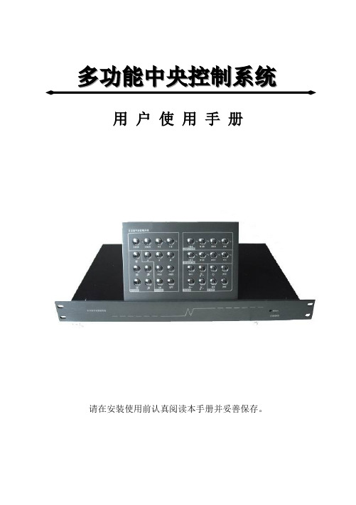
多功能中央控制系统用户使用手册请在安装使用前认真阅读本手册并妥善保存。
目录:特点介绍 (2)安全注意事项 (3)技术规格 (4)第一章系统结构 (6)1.1 主机 (6)1.1.1 前面板 (6)1.1.2 后面板 (6)1.2 轻触式按键面板 (7)1.2.1 前面板 (7)1.2.2 后面板 (7)1.3 轻触式简化按键面板 (8)1.3.1 前面板 (8)1.3.2 后面板 (8)1.4 感应式按键面板 (9)1.4.1 前面板 (9)1.4.2 后面板 (9)第二章系统连接 (10)2.1 基本系统连接 (10)2.1.1 投影机电源连接 (10)2.1.2 投影幕电源连接 (11)2.1.3 RS232 串口连接 (11)2.1.4 中控多功能线连接 (11)2.2 网络系统连接 (12)第三章系统功能操作 (13)3.1 基本按键功能 (13)3.2 红外学习功能 (17)3.3 RS232 学习功能 (17)日常维护与注意 (18)常见问题与解决 (18)附件清单 (20)特点介绍:欢迎使用本设备,在使用本设备之前,请您先详细阅读本《用户使用手册》,愿这本详尽的《用户使用手册》能帮您更加熟练地掌握操作方法,更加充分地享受本设备给您带来的方便。
本设备的特点:1、面板可选:提供轻触式按键面板和感应式按键面板两种选择,使用铝合金面板设计,美观耐用;2、独立的预览和投影按键,尽显人性化设计,可单独进行预览或投影切换;3、特有ESD静电保护功能,带电拔插不会损坏内部元器件;4、智能控制、简捷易用:实现一键开机即用、关机即走,投影机延时关机、银幕联动升降;5、安装设置方便快捷,维护简单:采用串口控制投影机,避免红外学习难,容易受干扰等问题。
内置几十种品牌共几百种型号投影机的控制码,轻松设置,并可免费自由升级;6、密码式红外学习功能,无须配置专业学习器,使用更简单,存储更可靠;7、内置数字音量调节,调节音量更轻松(准确),能提供高保真声音输出;8、VGA带宽440MHz,带长线驱动,图像的亮度和对比度能提高1/3,图像更亮丽清晰;9、接口丰富:2路独立可编程RS-232控制接口;1路计算机RS-232控制接口;4进2出VGA切换;6进2出音频切换;2进2出VIDEO 切换;1路投影机电源输出;1路银幕控制输出;2路可编程红外发射接口;2路麦克风输出接口;1路网络接口;1路RS485接口;5路预留IO接口;11、带网络接口,实现在局域网内远程控制多媒体设备,方便设备维护管理;12、控制面板与主机使用RS485接口连接,可实现长距离控制,提高信号传输的可靠性;13、5路预留IO口,可方便连接IC卡或电子锁等外接设备;安全注意事项:为防止火灾或漏电,请勿让本设备雨淋或潮湿。
- 1、下载文档前请自行甄别文档内容的完整性,平台不提供额外的编辑、内容补充、找答案等附加服务。
- 2、"仅部分预览"的文档,不可在线预览部分如存在完整性等问题,可反馈申请退款(可完整预览的文档不适用该条件!)。
- 3、如文档侵犯您的权益,请联系客服反馈,我们会尽快为您处理(人工客服工作时间:9:00-18:30)。
Temperature rating
Ordering information
Standard colours
Operating temperature range:-30°C to +105°C Minimum recovery temperature:
+150°C
Inside diameter Wall thickness Standard package D (min)
Expanded as supplied d (max)Recovered after heating W (nom)Recovered after heating Spool quantity mm mm mm m Ordering description 1.60.80.4100TRV-160-colour code 2.4 1.20.5100TRV-240-colour code 3.2 1.60.5100TRV-320-colour code 4.8 2.40.5100TRV-480-colour code 6.4 3.20.5100TRV-620-colour code 9.5 4.50.6100TRV-950-colour code 12.7 6.40.850TRV-1270-colour code 15.07.50.850TRV-1500-colour code 19.09.50.850TRV-1900-colour code 25.412.7 1.050TRV-2540-colour code 32.016.0 1.050TRV-3200-colour code 38.019.0 1.050TRV-3800-colour code 51.025.5 1.050TRV-5100-colour code 76.038.1 1.025TRV-7625-colour code 102.0
51.0
1.3
25
TRV-10200-colour code
Colour Black Red Yellow Blue Green White Code
2
4
5
6
9
•Self extinguishing •Non-irradiated •Flexible
•Good mechanical performance
TRV
Electrically insulating PVC heat-shrinkable tubing
TRV is a self extinguishing, flexible, non-irradiated, Poly Vinyl Chloride heat-
shrinkable tubing. The product provides excellent mechanical performance and is resistant to a wide range of chemicals and solvents.
TRV finds extensive use in the Automotive and Commercial Electronics industries.
Raychem Interconnect Cheney Manor Industrial Estate Swindon, Wiltshire SN2 2QE Tel:(44)-1793-528171 Fax:(44)-1793-616652All of the above information, including illustrations, is believed to be reliable. Users, however, should independently evaluate the suitability of each product for their application. Tyco Electronics makes no warranties as to the accuracy or completeness of the information and disclaims any liability regarding its use. Tyco Electronics only obligations are those in the Standard Terms and Conditions of Sale for this product and in no case will Tyco Electronics be liable for any incidental, indirect or consequential damages arising from the sale, resale, use or misuse of the product. Tyco Electronics Specifications are subject to change without notice. In addition Tyco Electronics reserves the right to make changes in materials or processing, without notification to the Buyer, which do not affect compliance with any applicable specification.
TRV
RI0037.1299 Raychem and TRV are trademarks of Raychem Interconnect, a division of Tyco Electronics Corporation.
Performance
Specifications Heat ageing:168 h at 136°C UL 224 Corrosion resistance:No corrosion ASTM D2671 Dielectric strength:15 MV/m min IEC 243
Fluid resistance 24h at 23°C, ISO 37:Tensile strength 12 MPa (min)
Elongation 150% (min)
Test Fluids:
IRM 902
Lubricating oil 0-149
Anti-icing fluid
Flammability:Pass UL 224 VW1
For full product performance details consult Raychem Specification RK 6147/1. Raychem Specification RK 6147/1.。
