si2301中文资料
si2301中文资料

在线互动式文档分享平台,在这里,您可以和千万网友分享自己手中的文档,全文阅读其他用户的文档,同时,也...SI2301在这幅图的作用是什么。
这是复位电路吗?百度知道...当作一个开关管用。
...按键按下SI2301关闭,VCC断电。
按键松开,SI2301导通,VCC得电。
SI2301在这幅图的作用是什么。
这是复位电路吗?百度知道答:当作一个开关管用。
座子是电源插针。
按键按下SI2301关闭,VCC断电。
按键松开,SI2301导通,VCC得电。
si2301开关管应用电路_图片素材-斯卡依乐园zhidao.baiduP沟道的MOS管SI2301的一个电路-ARM技术论坛-ARM嵌入式论坛...斯卡依头像>图片素材>si2301开关管应用电路>正文/删除/报错/投诉内容【si2301开关管应用电路第...如何做一个承受2A的开关电路_百度知道STM32F429开发板上的一个电路,其中SI2301是个P沟道的MOS 管。
里边的话是不是说错了?如果更改为:如果VREF+... PMOS开关电路一直导通使用PMOS(si2301)做开关电路,... 控制管脚由单片机控制,负载电压是......完全可以作开关,且几乎没有压降(2A负载下,只有0.2V以下的压降),下面给...SI2301这个mos管的开关频率是多少?可以用在开关电源后面吗... 使用PMOS(si2301)做开关电路,无论A点悬空或接地,mos管保持导通,B点的输出电压一直为24V,两个电阻能...使用PMOS(si2301)做开关电路,无论A点悬空或接地,mos管... SI2301,P沟道MOS管,耐压20V,电流2.8A,峰值电流10A。
...一般开关电源都用高耐压N沟道MOS管,它就不合适了。
...PMOS开关电路一直导通使用PMOS(si......你是b悬空量的吧,在b点接10k左右的电阻试试。
SI2301CDS-T1-GE3中文资料

Vishay SiliconixSi2301CDSP-Channel 20-V (D-S) MOSFET FEATURES•Halogen-free Option Available•TrenchFET ® Power MOSFETAPPLICATIONS •Load SwitchMOSFET PRODUCT SUMMARYV DS (V)R DS(on) (Ω)I D (A)a Q g (Typ.)- 200.112 at V GS = - 4.5 V - 3.1 3.3 nC0.142 at V GS = - 2.5 V- 2.7Notes:a. Based on T C = 25 °C.b. Surface Mounted on 1" x 1" FR4 board.c. t = 5 s.d. Maximum under Steady State conditions is 175 °C/W.ABSOLUTE MAXIMUM RATINGS T A = 25°C, unless otherwise notedParameter Symbol Limit U nitDrain-Source Voltage V DS - 20VGate-Source Voltage V GS ± 8Continuous Drain Current (T J = 150 °C)T C = 25 °C I D- 3.1A T C = 70 °C - 2.5T A = 25 °C - 2.3b, c T A = 70 °C - 1.8b, cPulsed Drain Current I DM - 10Continuous Source-Drain Diode CurrentT C = 25 °C I S - 1.3T A = 25 °C - 0.72b, c Maximum Power Dissipation T C = 25 °C P D 1.6WT C = 70 °C 1.0T A = 25 °C 0.86b, c T A = 70 °C 0.55b, cOperating Junction and Storage T emperature Range T J , T stg - 55 to 150°C THERMAL RESISTANCE RATINGSParameter Symbol Typical Maximum UnitMaximum Junction-to-Ambient b, d ≤ 5 s R thJA 120145°C/WMaximum Junction-to-Foot (Drain)Steady State R thJF 6278Vishay SiliconixSi2301CDSNotes:a. Pulse test; pulse width ≤ 300 µs, duty cycle ≤ 2 %.b. Guaranteed by design, not subject to production testing.Stresses beyond those listed under “Absolute Maximum Ratings” may cause permanent damage to the device. These are stress ratings only, and functional operation of the device at these or any other conditions beyond those indicated in the operational sections of the specifications is not implied. Exposure to absolute maximum rating conditions for extended periods may affect device reliability.MOSFET SPECIFICATIONS T J = 25°C, unless otherwise notedParameter Symbol Test Conditions Min.Typ.Max.U nit StaticDrain-Source Breakdown Voltage V DS V DS = 0 V, I D = - 250 µA- 20VV DS Temperature Coefficient ΔV DS /T J I D = - 250 µA - 18mV/°C V GS(th) T emperature Coefficient ΔV GS(th)/T J 2.2Gate-Source Threshold Voltage V GS(th) V DS = V GS , I D = - 250 µA - 0.4- 1V Gate-Source LeakageI GSS V DS = 0 V , V GS = ± 8 V ± 100nA Zero Gate Voltage Drain Current I DSS V DS = - 20 V , V GS = 0 V - 1µA V DS = - 20 V, V GS = 0 V , T J = 55 °C- 10On-State Drain Current aI D(on) V DS ≤ - 5 V , V GS = - 4.5 V - 6A Drain-Source On-State Resistance aR DS(on) V GS = - 4.5 V, I D = - 2.8 A 0.0900.112ΩV GS = - 2.5 V, I D = - 2.0 A 0.1100.142Forward T ransconductance a g fsV DS = - 5 V , I D = - 2.8 A2.0SDynamic bInput Capacitance C iss V DS = - 10 V , V GS = 0 V , f = 1 MHz405pFOutput CapacitanceC oss 75Reverse Transfer Capacitance C rss 55Total Gate Charge Q g V DS = - 10 V , V GS = - 4.5 V , ID = - 3 A 5.510nC V DS = - 10 V , V GS = - 2.5 V , I D = - 3 A 3.36Gate-Source Charge Q gs 0.7Gate-Drain Charge Q gd 1.3Gate Resistance R g f = 1 MHz6.0ΩTurn-On Delay Time t d(on) V DD = - 10 V, R L = 10 ΩI D = - 1 A, V GEN = - 4.5 V , R G = 1 Ω1120ns Rise Timet r 3560Turn-Off Delay Time t d(off) 3050Fall Timet f1020Drain-Source Body Diode Characteristics Continuous Source-Drain Diode Current I S T C = 25 °C- 1.3A Pulse Diode Forward Current a I SM - 10Body Diode VoltageV SD I S = - 0.7 A- 0.8- 1.2V Body Diode Reverse Recovery Time t rr I F = - 3.0 A, dI/dt = 100 A/µs, T J = 25 °C3050ns Body Diode Reverse Recovery Charge Q rr 2550nC Reverse Recovery Fall Time t a 15nsReverse Recovery Rise Timet b15Output CharacteristicsOn-Resistance vs. Drain Current and Gate VoltageTransfer CharacteristicsCapacitanceOn-Resistance vs. Junction TemperatureThreshold VoltageSingle Pulse PowerVishay SiliconixSi2301CDSTYPICAL CHARACTERISTICS 25°C, unless otherwise notedVishay Siliconix maintains worldwide manufacturing capability. Products may be manufactured at one of several qualified locations. Reliability data for Silicon Technology and Package Reliability represent a composite of all qualified locations. For related documents such as package/tape drawings, part marking, and reliability data, see /ppg?68741.Normalized Thermal Transient Impedance, Junction-to-FootDisclaimer Legal Disclaimer NoticeVishayAll product specifications and data are subject to change without notice.Vishay Intertechnology, Inc., its affiliates, agents, and employees, and all persons acting on its or their behalf (collectively, “Vishay”), disclaim any and all liability for any errors, inaccuracies or incompleteness contained herein or in any other disclosure relating to any product.Vishay disclaims any and all liability arising out of the use or application of any product described herein or of any information provided herein to the maximum extent permitted by law. The product specifications do not expand or otherwise modify Vishay’s terms and conditions of purchase, including but not limited to the warranty expressed therein, which apply to these products.No license, express or implied, by estoppel or otherwise, to any intellectual property rights is granted by this document or by any conduct of Vishay.The products shown herein are not designed for use in medical, life-saving, or life-sustaining applications unless otherwise expressly indicated. Customers using or selling Vishay products not expressly indicated for use in such applications do so entirely at their own risk and agree to fully indemnify Vishay for any damages arising or resulting from such use or sale. Please contact authorized Vishay personnel to obtain written terms and conditions regarding products designed for such applications.Product names and markings noted herein may be trademarks of their respective owners.元器件交易网。
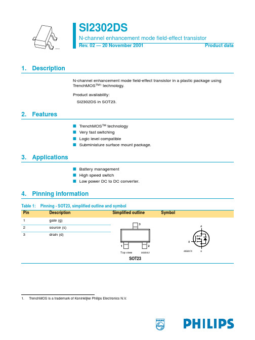
SI2302DS中文资料
SI2302DS
N-channel enhancement mode field-effect transistor
120
Pder (%)
80
03aa17
120 Ider (%)
80
03aa25
40
40
0
0
50
100
150
200
Tsp (oC)
Pder
=
-------P----t--o--t------P
© Koninklijke Philips Electronics N.V. 2001. All rights reserved.
4 of 12
Philips Semiconductors
SI2302DS
N-channel enhancement mode field-effect transistor
ID = 10 µA; VGS = 0 V ID = 1 mA; VDS = VGS; Figure 9 VDS = 20 V; VGS = 0 V
Tj = 25 °C Tj = 55 °C VGS = ±8 V; VDS = 0 V VGS = 4.5 V; ID = 3.6 A; Figure 7 and 8 VGS = 2.5 V; ID = 3.1 A; Figure 7 and 8
VGS(th) gate-source threshold voltage
IDSS
drain-source leakage current
IGSS RDSon
gate-source leakage current drain-source on-state resistance
Dynamic characteristics
si2301中文资料
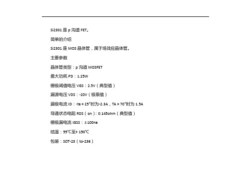
Si2301是p沟道FET。
简单的介绍
Si2301是MOS晶体管,属于场效应晶体管。
主要参数
晶体管类型:p沟道MOSFET
最大功耗PD:1.25W
栅极阈值电压VGS:2.5V(典型值)
漏源电压VDS:-20V(极限值)
漏极电流ID:-ta = 25°时为-2.3A,TA = 70°时为1.5A 导通状态电阻RDS(on):0.145ohm(典型值)
栅极漏电流IGSS:±100na
结温:55℃至+ 150℃
包装:SOT-23(to-236)
替代型号
WT-2301 WTC2301 SMG2301 CES2301 KI2301BDS
包装类型
SOT-23
什么是MOS晶体管
MOS晶体管是金属氧化物半导体场效应晶体管。
或金属绝缘体的半导体。
双极型晶体管放大输入电流的小变化,并在输出端输出大的电流变化。
双极晶体管的增益定义为输出与输入电流之比(β)。
另一个称为FET的晶体管将输入电压的变化转换为输出电流的变化。
FET的增益等于其电导率,其定义为输出电流变化与输入电压变化之比。
FET的名称还来自以下事实:它的输入(称为栅极)通过在绝缘层上投射电场来影响流过晶体管的电流。
实际上,没有电流流过绝缘体,因此FET的栅极电流非常小。
最常见的FET 使用二氧化硅薄层作为栅电极下方的绝缘体。
这种晶体管称为金属氧化物半导体(MOS)晶
体管或金属氧化物半导体场效应晶体管(MOSFET)。
由于MOS晶体管更小,功率效率更高,因此在许多应用中它们已取代了双极型晶体管。
2SA2013中文资料(ONSEMI)中文数据手册「EasyDatasheet - 矽搜」

Unit µA µA MHz
200 (360)400
本文描述或包含没有规范,能够处理应用需要极高的可靠性,如生命支持系统,飞机的控制系统或其他应用程序的 故障可合理预期会导致严重的身体任何及所有SANYO产品和/或财产损失.使用任何SANYO产品中,在此类应用中描述或包 含前与您的SANYO代表就近请教.
芯片中文手册,看全文,戳
订购数量: ENN6307B
2SA2013 / 2SC5566
2SA2013 / 2SC5566 DC / DC转换器应用
应用
•
PNP / NPN外延平面硅晶体管
继电器驱动器,灯驱动器,电机驱动器,闪存.
特征
• • • • • •
采用FBET和MBIT过程. 高电流容量. 低集电极 - 发射极饱和电压. 高速切换. 超小型封装facilitales 小型化的终端产品. 高允许功耗.
4
IC - VCE
mA 70 mA 80 90mA 100mA A 60m 50mA 40mA 30mA 20mA 10mA
--3
3
--2 集电极电流,IC - 一个 --1
2
--10mA
集电极电流,IC - 一个 1
0
IB=0mA
0 --0.4 --0.8 --1.2 集电极 - 发射极电压VCE - V --1.6 --2.0 IT00152
--25° C
5°C Ta=7 25°C
饱和电压 )° -C 毫伏 10 ,VCE(SAT --25 7 5 3 2 1.0 0.01 2 3 5 7 0.1
°C a=75 T 25°C
2 3
5 7 1.0
2
3
集电极电流,IC - 一个 10000 7 5 3 2 1000 7 5 集电极 - 发射极 3 2 100 ,VCE(SAT) - 毫伏 饱和电压 7 ° Ta=75 C 5
BZT52-B系列单极性电阻芯片在SOD123包装中的稳压电器数据手册说明书

BZT52-B seriesSingle Zener diodes in a SOD123 packageRev. 1 — 20 December 2017Product data sheet1 1 Product profile1.1General descriptionGeneral-purpose Zener diodes in a SOD123 small Surface-Mounted Device (SMD)plastic package.1.2Features and benefits•Total power dissipation: ≤ 590 mW•Wide working voltage range: nominal 2.4 V to 75 V (E24 range)•Small plastic package suitable for surface-mounted design •Low differential resistance •B selection•AEC-Q101 qualified1.3Applications•General regulation functions1.4Quick reference data[1]Pulse test: t p ≤ 300 μs; δ ≤ 0.02.[2]Device mounted on an FR4 Printed-Circuit Board (PCB), single-sided copper, tin-plated and standard footprint.[3]Device mounted on an FR4 PCB, single-sided copper, tin-plated, mounting pad for cathode 1 cm 2.Single Zener diodes in a SOD123 package 2Pinning information[1]The marking bar indicates the cathode.3Ordering information[1]The series consists of 37 types with nominal working voltages from 2.4 V to 75 V.4MarkingSingle Zener diodes in a SOD123 package 5Limiting valuesTable 5. Limiting valuesIn accordance with the Absolute Maximum Rating System (IEC 60134).[1]t p = 100 μs; square wave; T j = 25 °C prior to surge.[2]Device mounted on an FR4 PCB, single-sided copper, tin-plated and standard footprint.[3]Device mounted on an FR4 PCB, single-sided copper, tin-plated, mounting pad for cathode 1 cm2.6Thermal characteristics[1]Device mounted on an FR4 Printed-Circuit Board (PCB),single-sided copper, tin-plated and standard footprint.[2]Device mounted on an FR4 PCB, single-sided copper, tin-plated, mounting pad for cathode 1 cm2.[3]Soldering point of cathode tab.7CharacteristicsTable 7. CharacteristicsT = 25 °C unless otherwise specified.[1]Pulse test: t p ≤ 300 μs; δ ≤ 0.02.Single Zener diodes in a SOD123 package Table 8. Characteristics per type; BZT52-B2V4 to BZT52-B24= 25 °C unless otherwise specified.T[1] f = 1 MHz; V R = 0 V[2]t p = 100 μs; T amb = 25 °CSingle Zener diodes in a SOD123 packageTable 9. Characteristics per type; BZT52-B27 to BZT52-B51T= 25 °C unless otherwise specified.[1] f = 1 MHz; V R = 0 V[2]t p = 100 μs; T amb = 25 °CTable 10. Characteristics per type; BZT52-B56 to BZT52-B75T = 25 °C unless otherwise specified.[1] f = 1 MHz; V R = 0 V[2]t p = 100 μs; T amb = 25 °CSingle Zener diodes in a SOD123 package8Test information8.1Quality informationThis product has been qualified in accordance with the Automotive Electronics Council(AEC) standard Q101 - Stress test qualification for discrete semiconductors, and issuitable for use in automotive applications.Single Zener diodes in a SOD123 package 9Package outline10SolderingSingle Zener diodes in a SOD123 package 11Revision historySingle Zener diodes in a SOD123 package 12Legal information12.1 Data sheet status[1]Please consult the most recently issued document before initiating or completing a design.[2]The term 'short data sheet' is explained in section "Definitions".[3]The product status of device(s) described in this document may have changed since this document was published and may differ in case of multipledevices. The latest product status information is available on the Internet at URL .12.2 DefinitionsDraft — The document is a draft version only. The content is still under internal review and subject to formal approval, which may result in modifications or additions. Nexperia does not give any representations or warranties as to the accuracy or completeness of information included herein and shall have no liability for the consequences of use of such information.Short data sheet — A short data sheet is an extract from a full data sheet with the same product type number(s) and title. A short data sheet is intended for quick reference only and should not be relied upon to contain detailed and full information. For detailed and full information see the relevant full data sheet, which is available on request via the local Nexperia sales office. In case of any inconsistency or conflict with the short data sheet, the full data sheet shall prevail.Product specification — The information and data provided in a Product data sheet shall define the specification of the product as agreed between Nexperia and its customer, unless Nexperia and customer have explicitly agreed otherwise in writing. In no event however, shall an agreement be valid in which the Nexperia product is deemed to offer functions and qualities beyond those described in the Product data sheet.12.3 DisclaimersLimited warranty and liability — Information in this document is believed to be accurate and reliable. However, Nexperia does not give any representations or warranties, expressed or implied, as to the accuracyor completeness of such information and shall have no liability for the consequences of use of such information. Nexperia takes no responsibility for the content in this document if provided by an information source outside of Nexperia. In no event shall Nexperia be liable for any indirect, incidental, punitive, special or consequential damages (including - without limitation -lost profits, lost savings, business interruption, costs related to the removal or replacement of any products or rework charges) whether or not such damages are based on tort (including negligence), warranty, breach of contract or any other legal theory. Notwithstanding any damages that customer might incur for any reason whatsoever, Nexperia's aggregate and cumulative liability towards customer for the products described herein shall be limited in accordance with the Terms and conditions of commercial sale of Nexperia.Right to make changes — Nexperia reserves the right to make changesto information published in this document, including without limitation specifications and product descriptions, at any time and without notice. This document supersedes and replaces all information supplied prior to the publication hereof.Applications — Applications that are described herein for any of these products are for illustrative purposes only. Nexperia makes no representation or warranty that such applications will be suitable for the specified use without further testing or modification. Customers are responsible for the design and operation of their applications and products using Nexperia products, and Nexperia accepts no liability for any assistance with applications or customer product design. It is customer’s sole responsibility to determine whether the Nexperia product is suitable and fit for the customer’s applications and products planned, as well as for the planned application and use of customer’s third party customer(s). Customers should provide appropriate design and operating safeguards to minimize the risks associated with their applications and products. Nexperia does not accept any liability related to any default, damage, costs or problem which is based on any weakness or default in the customer’s applications or products, or the application or use by customer’s third party customer(s). Customer is responsible for doing all necessary testing for the customer’s applications and products using Nexperia products in order to avoid a default of the applications and the products or of the application or use by customer’s third party customer(s). Nexperia does not accept any liability in this respect.Limiting values — Stress above one or more limiting values (as defined in the Absolute Maximum Ratings System of IEC 60134) will cause permanent damage to the device. Limiting values are stress ratings only and (proper) operation of the device at these or any other conditions above thosegiven in the Recommended operating conditions section (if present) or the Characteristics sections of this document is not warranted. Constant or repeated exposure to limiting values will permanently and irreversibly affect the quality and reliability of the device.Terms and conditions of commercial sale — Nexperia products aresold subject to the general terms and conditions of commercial sale, as published at /profile/terms, unless otherwise agreed in a valid written individual agreement. In case an individual agreement is concluded only the terms and conditions of the respective agreement shall apply. Nexperia hereby expressly objects to applying the customer’s general terms and conditions with regard to the purchase of Nexperia products by customer.No offer to sell or license — Nothing in this document may be interpreted or construed as an offer to sell products that is open for acceptance orthe grant, conveyance or implication of any license under any copyrights, patents or other industrial or intellectual property rights.Suitability for use in automotive applications — This Nexperia product has been qualified for use in automotive applications. Unless otherwise agreed in writing, the product is not designed, authorized or warranted tobe suitable for use in life support, life-critical or safety-critical systems or equipment, nor in applications where failure or malfunction of an Nexperia product can reasonably be expected to result in personal injury, death or severe property or environmental damage. Nexperia and its suppliers accept no liability for inclusion and/or use of Nexperia products in such equipment or applications and therefore such inclusion and/or use is at the customer's own risk.Single Zener diodes in a SOD123 packageQuick reference data — The Quick reference data is an extract of the product data given in the Limiting values and Characteristics sections of this document, and as such is not complete, exhaustive or legally binding.Export control — This document as well as the item(s) described herein may be subject to export control regulations. Export might require a prior authorization from competent authorities.Translations — A non-English (translated) version of a document is for reference only. The English version shall prevail in case of any discrepancy between the translated and English versions.12.4 TrademarksNotice: All referenced brands, product names, service names and trademarks are the property of their respective owners.Nexperia BZT52-B series Single Zener diodes in a SOD123 packagePlease be aware that important notices concerning this document and the product(s)described herein, have been included in section 'Legal information'.© Nexperia B.V. 2017.All rights reserved.For more information, please visit: Forsalesofficeaddresses,pleasesendanemailto:***************************Date of release: 20 December 2017Document identifier: BZT52-B_SERContents1 1 Product profile .................................................11.1General description ............................................11.2Features and benefits ........................................11.3Applications ........................................................11.4Quick reference data .........................................12Pinning information ............................................23Ordering information ..........................................24Marking .................................................................25Limiting values ....................................................36Thermal characteristics ......................................37Characteristics ....................................................38Test information ..................................................68.1Quality information .............................................69Package outline ...................................................710Soldering ..............................................................711Revision history ..................................................812Legal information (9)Mouser ElectronicsAuthorized DistributorClick to View Pricing, Inventory, Delivery & Lifecycle Information:N experia:BZT52-B11J BZT52-B39X BZT52-B4V7X BZT52-B75J BZT52-B75X BZT52-B7V5X BZT52-B68X BZT52-B6V2X BZT52-B8V2J BZT52-B13J BZT52-B27J BZT52-B3V6J BZT52-B4V3X BZT52-B5V6J BZT52-B9V1J BZT52-B16X BZT52-B18X BZT52-B36X BZT52-B3V3J BZT52-B5V1J BZT52-B7V5J BZT52-B12J BZT52-B2V4J BZT52-B33X BZT52-B47X BZT52-B6V8X BZT52-B10J BZT52-B20X BZT52-B24X BZT52-B3V0X BZT52-B51J BZT52-B56J BZT52-B43J BZT52-B43X BZT52-B68J BZT52-B11X BZT52-B3V3X BZT52-B8V2X BZT52-B6V8J BZT52-B9V1X BZT52-B13X BZT52-B15X BZT52-B2V7J BZT52-B3V9J BZT52-B12X BZT52-B18J BZT52-B27X BZT52-B3V6X BZT52-B4V7J BZT52-B6V2J BZT52-B5V1X BZT52-B2V7X BZT52-B30X BZT52-B3V9X BZT52-B47J BZT52-B62J BZT52-B20J BZT52-B2V4X BZT52-B33J BZT52-B36J BZT52-B4V3J BZT52-B56X BZT52-B22J BZT52-B22X BZT52-B24J BZT52-B39J BZT52-B3V0J BZT52-B51X BZT52-B15J BZT52-B16J BZT52-B30J BZT52-B5V6X BZT52-B62X BZT52-B10X。
金属硅地牌号和用途

金属硅的牌号和用途金属硅又称结晶硅或工业硅,制取高纯度的半导体材料以及金属硅品位达到99.999(5N)的纯度,是工业提纯的单质硅,主要用于生产有机硅应用于3C产业,制取高纯度的半导体材料外还能做配制有特殊用途的合金等多方面使用主要用作非铁基合金的添加剂。
硅是非金属元素,兰灰色,有金属色泽,性硬且脆。
硅的含量约占地壳质量的26%,原子量为28.80,密度为2.33g/m3 .熔点为1410℃,沸点为2355℃。
电阻率2140Ωm.其最常使用的牌号金属硅的分类通常按金属硅成分所含的铁、铝、钙三种主要杂质的含量来分类。
按照金属硅中铁、铝、钙的含量,可把金属硅分为553、441、411、421、3303、3305、2202、2502、1501、1101等不同的牌号。
SiMETAL : SPECIFICATION :文案大全2202#SI : 99% MIN.FE : 0.2% MAX. AL : 0.2% MAX.CA : 0.02% MAX. 3303#文案大全SI : 99% MIN.FE : 0.3% MAX. AL : 0.3% MAX.CA : 0.03% MAX.441#SI : 99% MIN.文案大全FE : 0.4% MAX. AL : 0.4% MAX.CA : 0.1% MAX.553#SI : 99% MIN.FE : 0.5% MAX. AL : 0.5% MAX.文案大全CA : 0.3% MAX.411#SI : 99% MIN.FE : 0.4% MAX. AL : 0.1% MAX.CA : 0.1% MAX. 文案大全421#SI : 99% MIN.FE : 0.4% MAX.AL : 0.2% MAX.CA : 0.1% MAX.规格说明文案大全Si441产品编号: ON-990911文案大全(1)Si 99% Min Fe 0.3% Max Al 0.3%Max Ca 0.03% Max(2)Si 99% Min Fe 0.4% MaxAl 0.4% Max Ca 0.1% MaxSize : 10-100 mm 90% MinPacking in plastic woven bags of 1MT net each用途:制取高纯度的半导体材料以及金属硅品位达到99.999(5N)的纯度,是工业提纯的单质硅,主要用于生产有机硅应用于3C产业,制取高纯度的半导体材料外还能做配制有特殊用途的合金等多方面使用,其中品位达到较低者使用在金属合金配料—铝硅系合金、硅黄铜合金、硅青铜合金等用途。
MOS管 si2301
I S - Source Current (A)
TJ = 150_C
TJ = 25_C
0.4
0.3
ID = 2.8 A
0.2
0.1
VGS(th)Variance (V)
1 0.2 0.4 0.6 0.8 1.0 1.2 1.4 1.6
VSD - Source-to-Drain Voltage (V)
Document Number: 70627 S-31990—Rev. E, 13-Oct-03
Notice
Legal Disclaimer Notice
Vishay
Specifications of the products displayed herein are subject to change without notice. Vishay Intertechnology, Inc., or anyone on its behalf, assumes no responsibility or liability for any errors or inaccuracies.
Document Number: 70627 S-31990—Rev. E, 13-Oct-03
Si2301DS
Vishay Siliconix
TYPICAL CHARACTERISTICS (25_C UNLESS NOTED)
Output Characteristics
10
10
VGS = 5, 4.5, 4, 3.5, 3 V
Vishay Siliconix
TYPICAL CHARACTERISTICS (25_C UNLESS NOTED)
Source-Drain Diode Forward Voltage 10
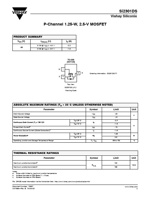
SI2301BDS_08中文资料

Vishay SiliconixSi2301BDSP-Channel 2.5-V (G-S) MOSFETFEATURES•Halogen-free Option AvailablePRODUCT SUMMARYV DS (V)R DS(on) (Ω)I D (A)b - 200.100 at V GS = - 4.5 V - 2.40.150 at V GS = - 2.5 V- 2.0Notes:a. Pulse width limited by maximum junction temperature.b. Surface Mounted on FR4 board, t ≤ 5 s.c. Surface Mounted on FR4 board.For SPICE model information via the Worldwide Web: /www/product/spice.htm.* Pb containing terminations are not RoHS compliant, exemptions may apply. ABSOLUTE MAXIMUM RATINGS T A = 25 °C, unless otherwise notedParameterSymbol 5 sSteady StateUnit Drain-Source Voltage V DS - 20VGate-Source VoltageV GS ± 8Continuous Drain Current (T J = 150 °C)b T A= 25 °C I D - 2.4- 2.2AT A = 70 °C- 1.9- 1.8Pulsed Drain Current aI DM - 10Continuous Source Current (Diode Conduction)b I S - 0.72- 0.6Power Dissipation bT A = 25 °C P D 0.90.7W T A = 70 °C 0.570.45Operating Junction and Storage T emperature RangeT J , T stg- 55 to 150°CTHERMAL RESISTANCE RATINGSParameter Symbol Typical Maximum UnitMaximum Junction-to-Ambient b R thJA120145°C/WMaximum Junction-to-Ambient c140175Vishay SiliconixSi2301BDSNotes:a. Pulse test: pulse width ≤ 300 µs duty cycle ≤ 2 %.b. For DESIGN AID ONLY, not subject to production testing.c. Switching time is essentially independent of operating temperature.Stresses beyond those listed under “Absolute Maximum Ratings” may cause permanent damage to the device. These are stress ratings only, and functional operation of the device at these or any other conditions beyond those indicated in the operational sections of the specifications is not implied. Exposure to absolute maximum rating conditions for extended periods may affect device reliability.SPECIFICATIONS T J = 25 °C, unless otherwise notedParameter Symbol T est Conditions LimitsUnitMin.Typ.Max.StaticDrain-Source Breakdown Voltage V DS V GS = 0 V, I D = - 250 µA - 20VGate Threshold Voltage V GS(th) V DS = V GS , I D = - 250 µA - 0.45- 0.95Gate-Body LeakageI GSS V DS = 0 V , V GS = ± 8 V ± 100 nAZero Gate Voltage Drain Current I DSS V DS = - 20 V , V GS = 0 V - 1µA V DS = - 20 V , V GS = 0 V, T J = 55 °C- 10On-State Drain Current aI D(on) V DS ≤ - 5 V , V GS = - 4.5 V - 6A V DS ≤ - 5 V , V GS = - 2.5 V - 3Drain-Source On-State Resistance a R DS(on) V GS = - 4.5 V , I D = - 2.8 A 0.0800.100ΩV GS = - 2.5 V , I D = - 2.0 A 0.1100.150Forward T ransconductance a g fs V DS = - 5 V , I D = - 2.8 A 6.5S Diode Forward Voltage V SDI S = - 0.75 A, V GS = 0 V- 0.80- 1.2VDynamic bTotal Gate Charge Q g V DS = - 6 V , V GS = - 4.5 VI D ≅ - 2.8 A4.510nCGate-Source Charge Q gs 0.7Gate-Drain Charge Q gd 1.1Input Capacitance C iss V DS = - 6 V , V GS = 0 V , f = 1 MHz375pFOutput CapacitanceC oss 95Reverse Transfer Capacitance C rss65Switching c Turn-On Time t d(on)V DD = - 6 V , R L = 6 ΩI D ≅ - 1.0 A, V GEN = - 4.5 VR g = 6 Ω2030nst r4060Turn-Off Timet d(off)3045t f2030On-Resistance vs. Drain CurrentGate ChargeCapacitanceOn-Resistance vs. Junction TemperatureSource-Drain Diode Forward VoltageOn-Resistance vs. Gate-to-Source VoltageSingle Pulse PowerVishay SiliconixSi2301BDSTYPICAL CHARACTERISTICS 25°C, unless otherwise notedVishay Siliconix maintains worldwide manufacturing capability. Products may be manufactured at one of several qualified locations. Reliability data for Silicon Technology and Package Reliability represent a composite of all qualified locations. For related documents such as package/tape drawings, part marking, and reliability data, see /ppg?72066.Normalized Thermal Transient Impedance, Junction-to-AmbientLegal Disclaimer NoticeVishayNoticeSpecifications of the products displayed herein are subject to change without notice. Vishay Intertechnology, Inc., or anyone on its behalf, assumes no responsibility or liability for any errors or inaccuracies.Information contained herein is intended to provide a product description only. No license, express or implied, by estoppel or otherwise, to any intellectual property rights is granted by this document. Except as provided in Vishay's terms and conditions of sale for such products, Vishay assumes no liability whatsoever, and disclaims any express or implied warranty, relating to sale and/or use of Vishay products including liability or warranties relating to fitness for a particular purpose, merchantability, or infringement of any patent, copyright, or other intellectual property right. The products shown herein are not designed for use in medical, life-saving, or life-sustaining applications. Customers using or selling these products for use in such applications do so at their own risk and agree to fully indemnify Vishay for any damages resulting from such improper use or sale.。
si2301中文资料_数据手册_参数
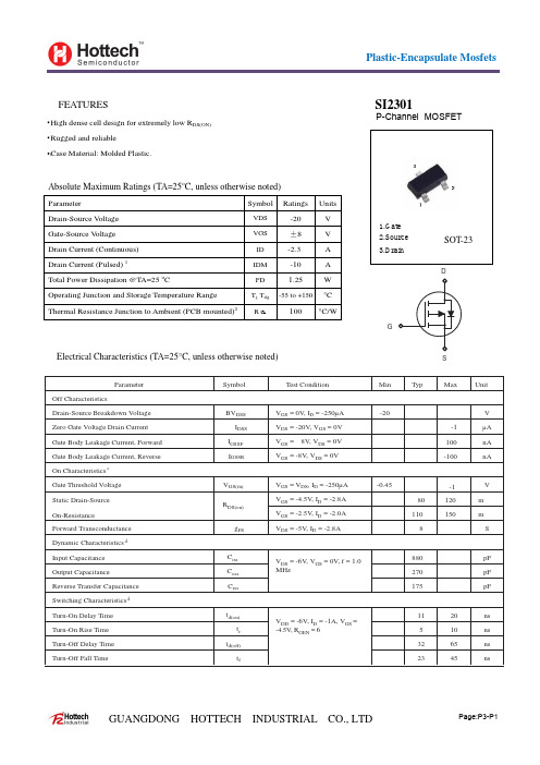
-20
V
-1
µA
100
nA
-100
nA
-0.45
-1
V
80
120
mΩ
110
150
mΩ
8
S
VDS = -6V, VGS = 0V, f = 1.0
100 °C/W
1.Gate 2.Source 3.Drain
SOT-23
D
G
Electrical Characteristics (TA=25°C, unless otherwise noted)
S
Parameter Off Characteristics Drain-Source Breakdown Voltage Zero Gate Voltage Drain Current Gate Body Leakage Current, Forward Gate Body Leakage Current, Reverse On Characteristics c Gate Threshold Voltage Static Drain-Source On-Resistance Forward Transconductance Dynamic Characteristics d Input Capacitance Output Capacitance Reverse Transfer Capacitance Switching Characteristics d Turn-On Delay Time Turn-On Rise Time Turn-Off Delay Time Turn-Off Fall Time
常用不锈钢牌号的主要用途

常用不锈钢牌号的主要用途■ 1Cr18Ni9Ti SUS321 321 奥氏体型使用广泛,适用于食品、化工、医药、原子能工业■ 0Cr25Ni20 SUS310S 310S 奥氏体型炉用材料■ 1Cr18Ni9 SUS302 302 奥氏体型经冷加工有高的强度,建筑用装饰部件■ 0Cr18Ni9 SUS304 304 奥氏体型作为不锈钢耐热钢使用最广泛,食品使用设备,一般化工设备、原子能工业用■ 00Cr19Ni10 SUS304L 304L 奥氏体型用于抗晶间腐蚀性要求高的化学,煤炭,石油产业的野外露天机器、建材、耐热零件及热出合理处理有困难的零件■ 0Cr17Ni14Mo2 奥氏体型适用在海水和其它介质中,主要作耐点蚀材料、照相、食品工业、沿海地区设施、绳索、CD 杆、螺栓、螺母■ 0Cr17Ni14Mo2 SUS316L 316L 奥氏体型为0Cr17Ni14Mo2超低碳钢,用于对抗晶间腐蚀性有特别要求的产品■ 1Cr18Ni12Mo2Ti 奥氏体型用于抗硫酸、磷酸、甲酸、乙酸的设备,有良好的耐晶间腐蚀性■ 0Cr18Ni12Mo2Ti 奥氏体型用于抗硫酸、磷酸、甲酸、乙酸的设备,有良好的耐晶间腐蚀性■ 0Cr18Ni10Ti 奥氏体型添加Ti提高耐晶腐蚀,不推荐作装饰部件■ 0Cr16Ni14 奥氏体型无磁不锈钢,做电子元件■0-1Cr20Ni14Si2 奥氏体型具有较高的高温强度及抗氧化性,对含硫气氛较敏感,在600-800摄氏度有析出相的脆化倾向,食用于制作承受应力的各种炉用构件■ 0Cr17Ni7 SUS301 301 奥氏体型适用于高强度构件,火车客车车厢用材料■ 00Cr18Ni5Mo3Si2 奥氏体型+铁素体型耐应力腐蚀破裂性能良好,具有较高的强度,适合含氯气离子的环境,用于炼油、化肥、造纸、石油、化工等工业、,制造热交换器冷凝器等■ 0Cr17(Ti)铁素体型用于洗衣机内桶冲压件,装饰用■ 00Cr12Ti 铁素体型用于汽车消音器,装饰用■ 0Cr13A1 SUS405 405 铁素体型从高温下冷却不产生显著硬化,汽轮机材料,淬火用部件,符合钢材■ 1Cr17 SUS430 430 铁素体型耐腐蚀性良好的通用钢种,建筑内装饰,重油燃烧器部件,用于家庭用具、家用电器部件。
SI2301DS场效应管原厂DCY品牌推荐
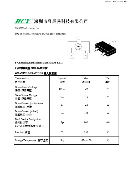
DMS2301AL / SI2301DS
■ELECTRICAL CHARACTERISTICS 電特性
(TA=25℃ unless otherwise noted 如無特殊說明,溫度爲 25℃)
Characteristic 特性參數
Symbol Min 符號 最小值
Typ 典型值
Max 最大值
Drain-Source Breakdown Voltage 漏極-源極擊穿電壓(ID = -250uA,VGS=0V)
t(off)
—
60
—
Unit 單位
V V V uA nA
mΩ mΩ
pF pF ns ns
Pulse Width<300μs; Duty Cycle<2.0%
(VGS=0V, VDS= -16V, TA=55℃)
IDSS
—
—
-1
-10
Gate Body Leakage 栅極漏電流(VGS=+8V, VDS=0V)
IGSS
—
—
+100
Static Drain-Source On-State Resistance 静态漏源導通電阻(ID= -2.4A,VGS= -4.5V)
Output Capacitance 輸出電容 (VGS=0V, VDS= -10V,f=1MHz)
COSS
—
120
—
Turn-ON Time 开启時間 (VDS= -10V, ID= -2.4A, RGEN=6Ω)
t(on)
—
8
—
Turn-OFF Time 关断時間 (VDS= -10V, ID= -2.4A, RGEN=6Ω)
si2301中文资料

Si2301是一种p沟FET。
简介
Si2301是一种MOS晶体管,是一种场效应晶体管。
主要参数
晶体管类型:p沟道MOSFET
最大功耗PD:1.25W
门阈值电压VGS:2.5V(典型值)
漏源电压VDS:-20V(极限值)
漏极电流ID:TA=25°时为2.3A,TA=70°时为1.5A
导通状态电阻RDS(On):0.145ohm(典型值)
栅漏电流IGSS:±100na
结温:55°C至+150°C
包装:SOT-23(to-236)
替代模型
WT-2301 WTC2301 SMG2301CES2301 KI2301BDS
包装类型
SOT-23
什么是MOS管:
MOS管是一种金属氧化物半导体场效应晶体管。
或者叫做金属绝缘体半导体。
双极晶体管放大输入电流的微小变化,然后在输出端输出大电流变化。
双极晶体管的增益定义为输出电流与输入电流之比(β)。
另一种晶体管称为(FET),它将输入电压的变化转化为输出电流的变化。
FET的增益等于它的跨导,定义为输出电流变化与输入电压变化的比率。
FET的名字也来源于它的输入(称为栅极),它通过在绝缘层上投射电场来影响流过晶体管的电流。
实际上,没有电流流过这个绝缘体,所以FET管的栅电流非常小。
最常见的场效应晶体管使用一层薄薄的二氧化硅作为栅极下的绝缘体。
金属氧化物晶体管(或称金属氧化
物晶体管,简称金属氧化物晶体管)。
由于MOS管体积更小,功率效率更高,在许多应用中,它们已经取代了双极晶体管。
si2301工作原理
在实际的电路应用中啊,SI2301就像是一个灵活的小助手。比如说在一些电源管理电路里,它可以用来控制电流的通断。就像在一个电路的小王国里,它负责开关那些电流的小河流。当需要给某个设备供电的时候,栅极接到信号,源极到漏极的通道打开,电流就像欢快的小水流一样流过去,给设备提供能量。当不需要供电的时候,栅极改变信号,通道关闭,电流就被拦住啦,就像关上了小水闸一样。
咱先来说说这个源极和漏极。这俩就像是两座房子,电子就像住在里面的小居民。正常情况下呢,电子在源极这个房子里待着,可要是有合适的信号,它们就会被允许跑到漏极那边去。这就像是源极的小居民得到了许可,要去漏极串门儿一样。
那这个许可谁来给呢?嘿就是栅极这个大管家啦。栅极可神奇了,它就像有魔法一样。当我们给栅极加上一定的电压信号的时候,就像是给这个大管家下达了指令。这个指令就像是一种神秘的力量,在栅极周围创造出了一个电场。这个电场啊,就像是一个无形的手,把源极和漏极之间的通道给改变了。如果这个电场足够强,就像是这个无形的手把通道变得超级宽敞,电子就可以轻松地从源极跑到漏极啦。就好比大管家把两座房子之间的路给拓宽了,小居民们就能欢快地跑来跑去啦。
si2301工作原理
嗨,小伙伴们!今天咱们来唠唠SI2301这个超有趣的小玩意儿的工作原理。
SI2301呢,是一种场效应管,它就像是一个超级智能的小门卫。你可以把它想象成住在电路这个大社区里的一个小管家。这个小管家有三个很重要的“触手”,也就是它的三个引脚啦,分别是源极(S)、漏极(D)和栅极(G)。
前苏联二极管参数表
前苏联二极管参数表前苏联二极管参数表1. 引言二极管是一种电子组件,具有非常重要的应用价值。
在过去的几十年里,前苏联产生了大量的二极管,这些二极管参数表记录了其性能特点、规格和用途等信息。
本文将深入探讨这些前苏联二极管参数表的内容和意义。
2. 背景在过去的几十年里,前苏联是一个相当重要的电子器件制造国家。
他们生产了大量的二极管,这些二极管在军事、航天、通信等领域发挥了重要作用。
前苏联的二极管参数表对于了解这些器件的性能特点至关重要。
3. 前苏联二极管参数表的内容前苏联二极管参数表包含了许多不同类型的二极管的参数信息。
其中包括但不限于:正向电流、反向电压、导通压降、最大功率、最大反向电流和封装类型等。
这些参数可以帮助我们了解二极管的工作条件和限制。
4. 前苏联二极管参数表的意义前苏联二极管参数表的意义在于提供了有关这些二极管性能特点的信息。
通过研究和分析这些参数,我们可以了解二极管的使用条件和限制,从而更好地应用和设计电子电路。
5. 个人观点和理解在我看来,前苏联二极管参数表是非常珍贵和有价值的。
这些参数表记录了前苏联在二极管领域的成就和贡献,也展示了他们在科学研究和技术开发方面的实力。
通过研究这些参数表,我们可以深入探讨前苏联的科技发展历程,了解他们在二极管技术方面的突破和创新。
6. 总结和回顾前苏联二极管参数表是对前苏联二极管性能特点的记录和总结。
通过深入分析这些参数表,我们可以全面、深刻和灵活地理解前苏联二极管的特点和性能限制。
这些参数表对于研究电子电路设计、科技历史以及前苏联的科技发展都具有重要价值。
7. 结束语本文深入探讨了前苏联二极管参数表的内容和意义。
通过研究这些参数表,我们可以更好地了解前苏联二极管的性能特点和限制,从而为电子电路设计和科技研究提供有价值的参考信息。
希望这篇文章能够增加大家对于前苏联二极管参数表的认识和理解。
在撰写这篇文章的过程中,我对前苏联二极管参数表产生了浓厚的兴趣。
FOSAN富信电子 二级管 1SS193 1SS181 1SS184 1SS226-产品规格书
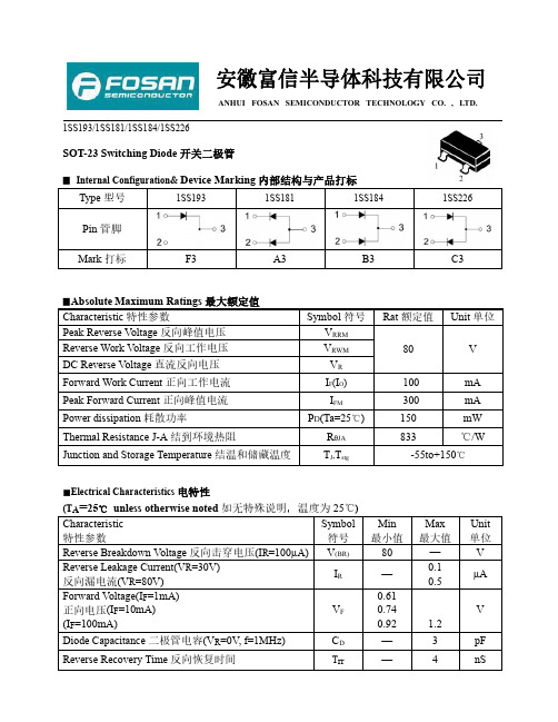
安徽富信半导体科技有限公司ANHUI FOSAN SEMICONDUCTOR TECHNOLOGY CO.,LTD.1SS193/1SS181/1SS184/1SS226SOT-23Switching Diode 开关二极管▉Internal Configuration&DeviceMarking 内部结构与产品打标Type 型号1SS1931SS1811SS1841SS226Pin 管脚Mark 打标F3A3B3C3▉AbsoluteMaximum Ratings 最大额定值Characteristic 特性参数Symbol 符号Rat 额定值Unit 单位Peak Reverse V oltage 反向峰值电压V RRM 80V Reverse Work Voltage 反向工作电压V RWMDC Reverse Voltage 直流反向电压V R Forward Work Current 正向工作电流I F (I O )100mA Peak Forward Current 正向峰值电流I FM300mA Power dissipation 耗散功率P D (Ta=25℃)150mW Thermal Resistance J-A 结到环境热阻R θJA 833℃/WJunction and Storage Temperature 结温和储藏温度T J ,T stg-55to+150℃■Electrical Characteristics 电特性(T A =25℃unless otherwise noted 如无特殊说明,温度为25℃)Characteristic 特性参数Symbol 符号Min 最小值Max 最大值Unit 单位Reverse Breakdown Voltage 反向击穿电压(I R =100µA)V (BR)80—V Reverse Leakage Current(V R =30V)反向漏电流(V R =80V)I R —0.10.5µA Forward V oltage(I F =1mA)正向电压(I F =10mA)(I F =100mA)V F 0.610.740.92 1.2V Diode Capacitance 二极管电容(V R =0V,f=1MHz)C D—3pF Reverse Recovery Time 反向恢复时间T rr—4nSANHUI FOSAN SEMICONDUCTOR TECHNOLOGY CO.,LTD.1SS193/1SS181/1SS184/1SS226■Typical Characteristic Curve典型特性曲线ANHUI FOSAN SEMICONDUCTOR TECHNOLOGY CO.,LTD.1SS193/1SS181/1SS184/1SS226■Dimension外形封装尺寸Symbol Dimensions In Millimeters Dimensions In Inches Min Max Min Max A 0.900 1.1500.0350.045A10.0000.1000.0000.004A20.900 1.0500.0350.041b 0.3000.5000.0120.020c 0.0800.1500.0030.006D 2.800 3.0000.1100.118E 1.200 1.4000.0500.055E1 2.2502.5500.0890.100e 0.950TYP0.037TYPe1 1.8002.0000.0710.079L 0.550REF0.022REFL10.3000.5000.0120.020θ0o8o 0o8o。
si2300导通电压
si2300导通电压Si2300是一款常用的N沟道MOS场效应管,具有导通电压较低的特点。
本文将围绕Si2300导通电压展开,从其特性、应用和优势等方面进行详细介绍。
一、Si2300的特性Si2300是一种低电压MOS管,其导通电压一般为2V左右。
导通电压是指在给定的电压条件下,MOS管开始导通的电压值。
对于Si2300而言,其导通电压较低,意味着只需较低的电压就能使其导通,具有较低的开启门限。
二、Si2300的应用1. 低电压电路:由于Si2300的导通电压较低,因此可以广泛应用于低电压电路中。
例如,手机、平板电脑等便携式设备中的电源管理电路,往往需要使用低电压MOS管来实现高效能的电源管理。
2. 电源开关:Si2300的导通电压较低,使其成为电源开关的理想选择。
在电源管理电路中,Si2300可以实现对电源的开关控制,确保电源的高效能运行。
3. DC-DC转换器:DC-DC转换器是将直流电压转换为不同电压级别的电源的设备。
在DC-DC转换器的控制电路中,Si2300可以用作开关管,实现高效的能量转换和电源管理。
三、Si2300的优势1. 低导通电压:Si2300具有较低的导通电压,使其在低电压电路中具有优势。
通过降低导通电压,Si2300可以减少功耗,提高电路的效率。
2. 低开启门限:Si2300的开启门限较低,意味着只需较小的输入信号就能使其导通。
这使得Si2300在控制电路中具有灵敏度高、反应速度快的特点。
3. 体积小巧:Si2300是一款小型化的MOS管,体积小巧。
这使得Si2300可以广泛应用于各种紧凑型电子设备中,如手机、平板电脑等。
4. 价格经济实惠:与其他高性能MOS管相比,Si2300的价格相对较低,使其成为广泛应用于各种电子设备的经济实惠选择。
Si2300是一款导通电压较低的N沟道MOS场效应管。
其特性使其在低电压电路中具有广泛的应用,如电源管理、DC-DC转换器等。
Si2300的优势包括低导通电压、低开启门限、体积小巧和价格经济实惠等。
有毒有害原辅材料代码表其它资料

有毒有害原辅材料代码表危险货物编号名称/CAS 号别名第 1 类爆炸品第1 项具有整体爆炸危险的物质和物品11035 三硝基甲苯118-96-7 TNT第 2 类压缩气体和易燃气体第1 项易燃气体21005 一氧化碳(非高原)630-08-0 21006 硫化氢7783-06-4 21037 氯乙烯;乙烯基氯75-01-4 21049 乙硼烷19287-45-7 二硼烷;硼乙烷第 3 项有毒气体23001 氟7782-41-4 23002 氯;氯气7782-50-5 液氯;氯气23003 氨7664-41-7 阿摩尼亚23005 磷化氢;膦7803-51-2 23006 砷化氢7784-42-1 砷化三氢;胂23012 四氧化二氮10102-44-0 二氧化氮;过氧化氮23014 二氟化氧7783-41-7 一氧化二氟23015 三氟化氯7790-91-2 23018 三氟化硼7637-07-2 氟化硼23021 五氟化氯13637-63-3 23028 氰460-19-5 氰气23032 六氟丙酮684-16-2 全氟丙酮23035 羰基氟353-50-4 氟化碳酰;氟氧化碳23038 碳酰氯75-44-5 光气23052 八氟异丁烯382-21-8 全氟异丁烯第3 类易燃液体第1 项低闪点液体31024 丙烯醛107-02-8 烯丙醛败酯醛31039 亚硝酸乙酯109-95-5 亚硝酰乙氧31048 3-氨基丙稀107-11-9 烯丙胺31050 二硫化碳75-15-0第2 项中闪点液体32050 苯71-43-2危险货物编号名称/CAS 号别名32065 2-丙稀-1-醇107-18-6 烯丙醇蒜醇乙烯甲醇32071 2-丁烯醛4170-30-3 巴豆醛β-甲基丙稀醛32078 3-丁烯-2-酮78-94-4 甲基乙烯基甲酮丁烯酮32089 氯甲基甲醚107-30-2 甲基氯甲醚氯二甲醚32114 二硫化二甲基624-92-0 二甲二硫甲基化二硫32150 氯甲酸甲酯79-22-1 氯碳酸甲酯32151 氯甲酸乙酯541-41-3 氯碳酸乙酯32160 丙腈107-12-0 乙基氰32161 丁腈,如:异丁腈78-82-0 异丙基氰正丁腈109-74-0 丙基氰;2-甲基丙腈32162 丙烯腈107-13-1 32163 甲基丙烯腈126-98-7 异丁烯腈异氰酸酯类易燃的,如:32164 异氰酸甲酯624-83-9 甲基异氰酸酯32182 六亚甲基亚胺111-49-9 高哌啶32183 甲(基)肼60-34-4 甲基联胺32184 二甲基肼,如:1,1-二甲基肼57-14-7 二甲基肼不对称1,2-二甲基肼540-73-8 对称二甲基肼;1,2-亚肼基甲烷第3 项高闪点液体33559 丙炔醇107-19-7 2-丙炔-1-醇炔丙醇33615 34-二甲基吡啶583-584 34-二甲基氮杂苯33631 无水肼302-01-2 无水联胺第4 类易燃固体、自燃物品和遇湿易燃物品第1 项易燃固体41010 24-二硝基苯酚51-28-5 二硝酚1-羟基-24-二硝基苯41056 硼烷17702-41-9 十硼烷;十硼氢41506 锰化合物锰尘、锰烟7439-96-5第2 项自燃物品危险货物编号名称/CAS 号别名42001 黄磷7723-14-0 42004 镍与镍化物7440-02-0 42031 戊硼烷19624-22-7 五硼烷第3 项遇湿易燃物品43038 磷化锌1314-84-7 二磷化三锌第5 类氧化剂和有机过氧化物第 1 项氧化剂51079 四硝基甲烷509-14-8 51520 重铬酸钠10588-01-9 红矾钠第 6 类毒害品和感染性物品第1 项毒害品氰化物,如:氰化钠143-33-9 山奈氰化钾151-50-8 山奈钾氰化钙592-01-8 61001 氰化银钾506-61-6 银氰化钾氰化镉542-83-6 氰化汞592-04-1 氰化高汞;二氰化汞氰化金钾13967-50-5 亚金氰化钾61003 氰化氢74-90-8 氢氰酸61006 砷及其无机化合物7440-38-2 61007 三氧化(二)砷1327-53-3 白砒;砒霜;亚砷(酸)酐亚砷酸盐类,如:亚砷酸钠7784-46-5 偏压砷酸钠61009 亚砷酸钾10124-50-2 偏亚砷酸钾祖母绿;翡翠绿;巴黎绿;帝绿;苔绿;乙酰亚砷酸铜12002-03-8 维也纳绿;草地绿;翠绿61010 五氧化(二)砷1303-28-2 砷(酸)酐61011 砷酸7778-39-4 原砷酸61013 三氯化砷7784-34-1 氯化亚砷危险货物编号名称/CAS 号别名61015 亚硒酸7783-00-8 亚硒酸盐类,如:亚硒酸钠10102-18-8 亚硒酸二钠61016 亚硒酸氢钠7782-82-3 重亚硒酸钠亚硒酸镁15593-61-0 硒酸盐类,如:61017 硒酸钠13410-01-0 61022 铊7440-28-0 金属铊铊化物,如:氧化亚铊1314-12-1 一氧化(二)铊61023 氧化铊1314-32-5 三氧化(二)铊碳酸亚铊6533-73-9 碳酸铊硫酸亚铊7446-18-6 硫酸铊61024 铍及其化合物7440-41-7 61026 四氧化锇20816-12-0 锇酸酐61028 五氧化二钒1314-62-1 钒(酸)酐一级无机汞化合物,如:氯化汞7487-94-7 61030 硝酸汞10045-94-0 硝酸高汞氯化汞7487-94-7 氯化高汞;二氯化汞;升汞碘化汞7774-29-0 碘化高汞;二碘化汞羰基金属,如:61031 羰基镍13463-39-3 四羰基镍;四碳镍五羰基铁13463-40-6 羰基铁61033 迭氮(化)钠26628-22-8 三氮化钠61051 三氯硝基甲烷76-06-2 氯化苦硝基三氯甲烷61055 六氯环戊二烯77-47-4 全氯环戊二烯61056 硝基苯98-95-3 二硝基苯全部异构61057 体582-29-0/ 99-65-0/100-25-4危险货物编号名称/CAS 号别名二氯甲(基)苯;苄叉二氯;aa-二氯61064 二氯化苄98-87-3 甲(基)苯61074 47-二硝基邻甲苯酚534-52-1 25-二硝基邻甲苯酚61077 乙撑亚胺151-56-4 氮丙环吖丙啶61079 一氯乙醛107-20-0 氯乙醛2-氯乙醛对称二氯四氟丙酮;敌锈酮;1,3-二61082 二氯四氟丙酮127-21-9 氯-1,1,3,3-四氟-2-丙酮61085 2-吡咯酮616-45-5 61086 二氯二甲醚542-88-1 对称二氯二甲醚丙酮合氰化氢;2- 基异丁腈;氰丙61088 丙酮氰醇75-86-5 醇三氯硫氯甲烷;过氯甲硫醇;四氯硫代61089 全氯甲硫醇594-42-3 碳酰61090 苯基硫醇108-98-5 苯硫酚巯基苯硫代苯酚61091 2-巯基乙醇60-24-2 硫代乙二醇2-羟基-1-乙硫醇一级有机汞化合物,如:乙酸汞1600-27-7 醋酸汞61093 乙酸甲氧基乙基汞151-38-2 醋酸甲氧基乙基汞氯化甲氧基乙基汞123-88-6 一级有机铊化合物,如:61095 乙酸亚铊563-68-8 乙酸铊;醋酸铊丙二酸铊2757-18-8 丙二酸亚铊一级有机锡化合物,如:61096 硫酸三乙基锡57-52-3 二丁基氧化锡818-08-6 氧化二丁基锡61097 四乙基铅78-00-2 发动机燃料抗爆混合物一级有机胂化合物,如:61098 二苯(基)胺氯胂578-94-9 吩吡嗪化氯;亚当氏气苯胂化二氯696-28-6 二氯苯胂61099 氟乙酸144-49-0 氟醋酸61100 氟乙酸钠62-74-8 氟醋酸钠危险货物编号名称/CAS 号别名61101 氯甲酸氯甲酯22128-62-7 61105 3-氯丙腈542-76-7 β-氯丙腈氰化--氯乙烷一级异氰酸酯类有毒的,如:61109 异氰酸苯酯103-71-9 苯基异氰酸酯一级二异氰酸酯类,如:甲苯-24- 二异氰酸酯61111 TDI 584-84-9 甲苯-2,4-二异氰酸酯584-84-9 2,4-二异酸甲苯酯61116 硫酸(二)甲酯77-78-1 61120 三-(1-吖丙啶基)氧化瞵545-55-1 涕巴,绝育磷一级生物碱类,如:马钱子碱357-57-3 二甲氧基士的宁;白路新61121 番木鳖碱57-24-9 二甲氧基马钱子碱;士的宁;士的年乌头碱302-27-2 附子精61125 一级有机磷固态农药,如:OO-二甲基-O-(1-甲基-2-N-甲基氨久效磷;纽瓦克;永伏虫基甲酰)乙烯基磷酸酯(含量gt25)6923-22-4 OO-二乙基-O-(4-硝基苯基)磷酸酯对氧磷311-45-5 OO-二甲基-O-(4-硝基苯基)流逐磷甲基对流磷;甲基1605 酸酯(含量gt15)298-00-0 O-乙基-O-(4-硝基苯基)苯基流代磷苯流磷;一皮恩酸酯(含量gt15)2104-64-5 O-甲基-O-(邻异丙氧基羰基苯基)流水胺硫磷;羧胺磷代磷酰胺酯24353-61-5 O-(3-氯-4-甲基-2-氧代-2H-1-苯并吡喃-7-基)-OO-二乙基流代磷酸酯(含量蝇毒磷;蝇毒;蝇毒硫磷gt30)56-72-4 S-(5-甲氧基-4-氧代-4H-吡喃-2-基甲基)-OO-二甲基硫赶磷酸酯(含量gt45)因毒磷;因毒硫磷2778-04-3 O-(4-溴-2,5-二氯苯基)-O-甲基苯对溴磷;溴苯磷基硫代瞵酸酯21609-90-5危险货物编号名称/CAS 号别名OO-二甲基-S-4-氧代-123-苯并三氮苯-34H-基)甲基二流代磷酸酯(含量保棉磷;谷硫磷;谷赛昂;甲基谷硫磷gt20)86-50-0 S-5-甲氧基-2-氧代-134-塞二唑-3(2H)-基)甲基-OO-二甲基二流代磷酸杀扑磷;麦达西磷,甲塞硫磷酯(含量gt40)950-37-8 对(5-氨基-3-苯基-1H-124-三唑-1-基)-NNNN-四甲基磷二酰胺(含量威菌磷;三唑磷胺gt20)1031-47-6 二乙基-13-亚二流戊环-2-基硫酰胺硫环磷;棉胺磷;棉环磷酯(含量gt15)947-02-4 甲胺磷;杀螨隆;多灭磷;多灭灵;克OS-二甲流代磷酰胺10265-92-6 螨隆;脱麦隆OO-二乙基-S-4-氧代-123-苯并三氮(杂)苯-34H-基)甲基二流代磷酸益棉磷;乙基保棉磷;乙基谷硫磷酯(含量gt25)2642-71-9 61126 一级有机磷液态农药,如:2-氯-3-(二乙氨基)-1-甲基-3-氧代磷胺;大灭虫-1-丙烯二甲基磷酸酯13171-21-6 甲基-3-二甲氧基磷酰基氧代-2- 速灭磷;磷君丁烯酸酯(含量gt5)7786-34-7 双(1-甲基乙基)氟磷酸酯55-91-4 丙氟磷;异丙氟;二异丙基氟磷酸酯2-氯-1-(2,4-二氯苯基)乙烯基二杀螟畏;毒虫畏乙基磷酸酯(含量gt20)470-90-6 3-二甲氧基磷氧基-N,N-二甲基异丁百治磷;百特磷烯酰胺(含量gt25)141-66-2 OO-二甲基-O-13-(二甲基氧甲酰保米磷基)丙烯-2-基磷酸酯122-10-1 四乙基焦磷酸酯107-49-3 特普OO-二乙基-O-2-(乙硫基)乙基硫代磷酸酯和OO-二乙基-S-2-(乙硫基)乙内吸磷;杀虱多;1059 基硫代磷酸酯混剂(含量gt3)8065-48-3 OO- 二乙基-O-4- 甲基亚磺酰苯丰索磷;丰索硫磷;线虫磷基硫代磷酸酯(含量gt4)115-90-2 OO 二甲基-S-2(甲氨基)-2-氧代乙氧乐果;氧化乐果;华果基硫代磷酸酯(含量gt40)1113-02-6危险货物编号名称/CAS 号别名(甲硫基)O-25-二氧-4- 苯基-OO- 氯甲硫磷;西拉硫磷二乙基流代磷酸酯21923-23-9 S-2-1- 氰基-1- 甲基乙基)氨基-2-氧代乙基-OO-二乙基硫代磷酸酯果虫磷;腈果3734-95-0 OO-二乙基-O-吡嗪基硫代磷酸酯(含治线磷;治线灵;硫磷嗪;嗪线磷量gt5 297-97-2 OO-二甲基-O-或S-2-(甲硫基)乙田乐磷硫代磷酸酯2587-90-8 二甲基-4-(甲基硫代)苯基磷酸酯甲硫磷;GC6505 3254-63-5 OO-二乙基-S-乙硫基甲基二流甲拌磷;3911;西梅脱代磷酸酯(含量gt2)298-02-2 OO-二乙基-S-2-(乙硫基)乙基二乙拌磷;敌死通流代磷酸酯(含量gt15)298-04-4 S-4-氯苯基硫代甲基-OO-二三硫磷;三赛昂乙基二流代磷酸酯(含量gt20)786-19-6 S-11- 二甲基乙基硫化甲特丁磷;特丁硫磷基-OO-二乙基二流磷酸酯13071-79-9 O-乙基-S-苯基乙基二流代磷酸酯(含地虫磷;地虫硫磷量gt6)944-22-9 OOOO-四乙基-S,S-亚甲基双(二乙硫磷;1240 蚜螨立死;益赛昂;易赛(含量gt25)563-12-2 流代磷酸酯)昂;乙赛昂;蚜螨S-氯甲基-OO-二乙基二流代磷酸酯氯甲磷;灭尔磷(含量gt15)24934-91-6 S-N-乙氧羰基-N-甲基-氨基甲酰甲基OO- 二乙基二流代磷酸酯含量gt30 灭蚜磷灭蚜硫磷2595-54-2 二乙基4-甲基-13-二流戊环-2-叉地安磷二噻磷氨基磷酸酯含量gt5 950-10-7 OO-二乙基-S-乙基亚砜基甲基二保棉丰甲拌磷亚砜异亚砜3911 亚砜流代磷酸酯2588-03-6 OO-二乙基-S-N-异丙基氨基甲酰甲.。
金属材料成分与代号
金属材料成分与代号7 铸铁_DZ2.15.10.1-1999 灰铸铁HT150 DZ2.15.10.2-1999 灰铸铁HT200 DZ2.15.10.3-1999 合金铸铁HT28-48CrMoDZ2.15.10.14-1999 球墨铸铁QT400-15DZ2.15.10.5-1999 灰铸铁QT500-7 DZ2.15.10.6-1999 灰铸铁QT600-36 铸钢DZ2.15.9.1-1999 碳素铸钢ZG230-450DZ2.15.9.8-1999 合金铸钢ZG15Cr1Mo1DZ2.15.9.7-1999 合金铸钢ZG15Cr2Mo1DZ2.15.9.6-1999 合金铸钢ZG15Cr1Mo1VDZ2.15.9.4-1999 合金铸钢ZG20CrMoDZ2.15.9.5-1999 合金铸钢ZG20CrMoVDZ2.15.8.2-1999 精铸不锈钢ZG1Cr13 DZ2.15.8.3-1999 精铸不锈钢ZG2Cr13 DZ2.15.8.4-1999 精铸不锈钢ZG1Cr11MoV11铜及铜合金DZ2.15.11.1-1999 工业纯铜T3DZ2.15.11.2-1999 黄铜H62 DZ2.15.11.3-1999 铅黄铜HPb59-1DZ2.15.11.4-1999 锡黄铜HSn62-1 DZ2.15.11.5-1999 锡黄铜HSn70-1 DZ2.15.11.16-1999 加硼锡黄铜HSn70-1BDZ2.15.11.6-1999 铝青铜QAl9-4 DZ2.15.11.7-1999 锡青铜QSn4-3 DZ2.15.11.8-1999 铍青铜QBe2DZ2.15.11.9-1999 铁白铜BFe30-1-1DZ2.15.10.8-1999 铸铝青铜DZ2.15.4.8-1999 不锈钢1Cr12MoDZ2.15.4.5-1999 不锈钢1Cr12W1MoV(1Cr12WMoV)序号标准号名称牌号页次DZ2.15.4.7-1999 不锈钢1Cr12Ni2W1Mo1V 5—15DZ2.15.4.17-1999 不锈钢1Cr12Ni3Mo2VN 5—17DZ2.15.4.2-1999 不锈钢2Cr13 5—19DZ2.15.4.6-1999 不锈钢2Cr11NiMo1V 5—21DZ2.15.4.14-1999 不锈钢2Cr11Mo1VNbN 5—23DZ2.15.4.9-1999 不锈钢2Cr12NiMo1W1V 5—25lDZ2.15.4.3-1999 不锈钢3Cr13 5—27DZ2.15.4.15-1999 高压锅炉用钢管10Cr9Mo1VNb 5—296DZ2.15.4.13-1999 司太立合金Co60Cr30W5 5—31DZ2.15.4.12-1999 高温合金GH2132 5—33DZ2.15.4.20-1999 高温合金GH4145 5—35DZ2.15.4.11-1999 耐热合金R-26 5—371、ZG1Cr13与1Cr13有什么区别?ZG1Cr13晶体结构为马氏体型,是不锈耐酸铸钢C(碳):0.08~0.15Si(硅):≤1.0Mn(锰):≤0.6Cr(铬):12.0~14.01Cr13 晶体组织为:马氏体型,为耐热钢C(碳)≤0.15Si(硅)≤1.00Mn(锰)≤1.00P(磷)≤0.035S(硫)≤0.030Cr(铬)11.50~13.50"ZG"是"铸钢"的意思不加这个前缀的不是铸钢(一般是指轧钢)2、ZG2Cr13材料名称:不锈耐酸钢铸件●特性及适用范围:性能与ZG1Cr13相同,由于含碳量比ZG1Cr13高,故具有更高的硬度,但耐蚀性较低,焊接性能较差。
稀有材料安全数据表
稀有材料安全数据表
1. 引言
稀有材料是指在自然界中含量非常稀少的元素或矿石,具有重要的工业和科研价值。
然而,这些材料通常具有高度的毒性和危险性,可能对人类健康和环境造成严重影响。
为了确保稀有材料的安全使用和处理,本文档提供了一份稀有材料安全数据表,帮助用户了解各种稀有材料的相关信息以及相应的安全注意事项。
2. 数据表
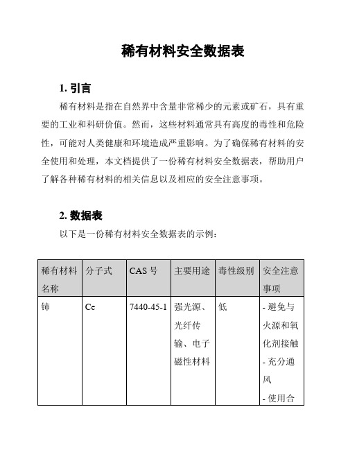
以下是一份稀有材料安全数据表的示例:
3. 安全注意事项解释
在表格中,我们提供了一些针对每种稀有材料的安全注意事项。
这里对一些术语进行解释:
- 毒性级别:分为低、中、高三个级别,分别表示毒性较低、
中等和较高。
- 避免与火源和氧化剂接触:稀有材料可能具有易燃性和氧化性,在接触火源或氧化剂时会引发危险事故,因此需避免与其接触。
- 充分通风:在使用稀有材料时,需要保证通风良好,以防止
有毒气体积聚和呼吸系统受到损害。
- 使用合适的个人防护装备:使用稀有材料时,应佩戴适当的
防护手套、眼镜、口罩等装备,以防止接触和吸入有害物质。
4. 结论
稀有材料的安全使用和处理对于保护人类健康和环境具有重要
意义。
通过了解稀有材料的安全数据以及相应的注意事项,用户可
以在使用这些材料时采取必要的安全措施,降低安全风险。
本文档
提供的稀有材料安全数据表可作为一个参考工具,促进稀有材料的
安全管理和保护。
> 注意:以上数据仅为示例,实际使用时请根据具体情况对稀
有材料的安全数据进行补充和调整。
- 1、下载文档前请自行甄别文档内容的完整性,平台不提供额外的编辑、内容补充、找答案等附加服务。
- 2、"仅部分预览"的文档,不可在线预览部分如存在完整性等问题,可反馈申请退款(可完整预览的文档不适用该条件!)。
- 3、如文档侵犯您的权益,请联系客服反馈,我们会尽快为您处理(人工客服工作时间:9:00-18:30)。
SI2301是一种P沟道场效应管。
简介:
SI2301是MOS管的一种,属于场效应管。
主要参数:
晶体管类型:P沟道MOSFET
最大功耗PD :1.25W
栅极门限电压VGS :2.5V(典型值)
漏源电压VDS :-20V(极限值)
漏极电流ID:TA=25°时:-2.3A,TA=70°时:-1.5A
通态电阻RDS(on):0.145ohm(典型值)
栅极漏电流IGSS:±100nA
结温:55℃to+150℃
封装:SOT-23(TO-236)
替代型号:
WT-2301 WTC2301 SMG2301 CES2301 KI2301BDS
封装类型:
SOT-23
P沟MOS晶体管:
金属氧化物半导体场效应(MOS)晶体管可分为N沟道与P沟道两大类,P沟道硅MOS场效应晶体管在N型硅衬底上有两个P+区,分别叫做源极和漏极,两极之间不通导,栅极上加有足够的正电压(源极接地)时,栅极下的N型硅表面呈现P型反型层,成为连接源
极和漏极的沟道。
改变栅压可以改变沟道中的电子密度,从而改变沟道的电阻。
这种MOS场效应晶体管称为P沟道增强型场效应晶体管。
如果N型硅衬底表面不加栅压就已存在P型反型层沟道,加上适当的偏压,可使沟道的电阻增大或减小。
这样的MOS场效应晶体管称为P沟道耗尽型场效应晶体管。
统称为PMOS晶体管。
P沟道MOS晶体管的空穴迁移率低,因而在MOS晶体管的几何尺寸和工作电压绝对值相等的情况下,PMOS晶体管的跨导小于N 沟道MOS晶体管。
此外,P沟道MOS晶体管阈值电压的绝对值一般偏高,要求有较高的工作电压。
它的供电电源的电压大小和极性,与双极型晶体管——晶体管逻辑电路不兼容。
PMOS因逻辑摆幅大,充电放电过程长,加之器件跨导小,所以工作速度更低,在NMOS 电路(见N沟道金属—氧化物—半导体集成电路)出现之后,多数已为NMOS电路所取代。
只是,因PMOS电路工艺简单,价格便宜,有些中规模和小规模数字控制电路仍采用PMOS电路技术。
PMOS集成电路是一种适合在低速、低频领域内应用的器件。
PMOS集成电路采用-24V电压供电。
如图5所示的CMOS-PMOS 接口电路采用两种电源供电。
采用直接接口方式,一般CMOS的电源电压选择在10~12V就能满足PMOS对输入电平的要求。
MOS场效应晶体管具有很高的输入阻抗,在电路中便于直接耦合,容易制成规模大的集成电路。
