4040DN103Z7中文资料
LM4040_05中文资料
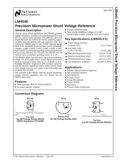
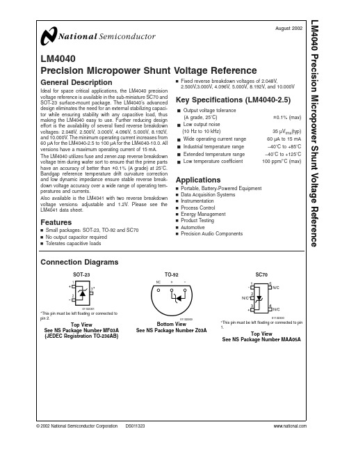
LM4040Precision Micropower Shunt Voltage ReferenceGeneral DescriptionIdeal for space critical applications,the LM4040precision voltage reference is available in the sub-miniature SC70and SOT-23surface-mount package.The LM4040’s advanced design eliminates the need for an external stabilizing capaci-tor while ensuring stability with any capacitive load,thus making the LM4040easy to use.Further reducing design effort is the availability of several fixed reverse breakdown voltages:2.048V,2.500V,3.000V,4.096V,5.000V,8.192V,and 10.000V.The minimum operating current increases from 60µA for the LM4040-2.5to 100µA for the LM4040-10.0.All versions have a maximum operating current of 15mA.The LM4040utilizes fuse and zener-zap reverse breakdown voltage trim during wafer sort to ensure that the prime parts have an accuracy of better than ±0.1%(A grade)at 25˚C.Bandgap reference temperature drift curvature correction and low dynamic impedance ensure stable reverse break-down voltage accuracy over a wide range of operating tem-peratures and currents.Also available is the LM4041with two reverse breakdown voltage versions:adjustable and 1.2V.Please see the LM4041data sheet.Featuresn Small packages:SOT-23,TO-92and SC70n No output capacitor requiredn Tolerates capacitive loadsn Fixed reverse breakdown voltages of 2.048V,2.500V,3.000V,4.096V,5.000V,8.192V,and 10.000VKey Specifications (LM4040-2.5)j Output voltage tolerance(A grade,25˚C)±0.1%(max)j Low output noise(10Hz to 10kHz)35µV rms (typ)j Wide operating current range 60µA to 15mA j Industrial temperature range −40˚C to +85˚C j Extended temperature range −40˚C to +125˚C j Low temperature coefficient100ppm/˚C (max)Applicationsn Portable,Battery-Powered Equipment n Data Acquisition Systems n Instrumentation n Process Controln Energy Management n Product Testing n AutomotivenPrecision Audio ComponentsConnection DiagramsSOT-23TO-92SC7001132301*This pin must be left floating or connected to pin 2.Top ViewSee NS Package Number MF03A (JEDEC Registration TO-236AB)01132303Bottom ViewSee NS Package Number Z03A01132330*This pin must be left floating or connected to pin1.Top ViewSee NS Package Number MAA05AApril 2005LM4040Precision Micropower Shunt Voltage Reference©2005National Semiconductor Corporation Ordering InformationIndustrial Temperature Range (−40˚C to +85˚C)Reverse Breakdown Voltage Tolerance at 25˚C and Average Reverse Breakdown Voltage Temperature CoefficientPackageNS Package NumberM3(SOT-23)M7(SC70)Z (TO-92)Supplied as 1000Units Tape andReelSupplied as 3000Units tape andReelSupplied as 1000Units Tape andReelSupplied as 3000Units Tape andReel±0.1%,100ppm/˚C max (A grade)LM4040AIM3-2.0LM4040AIM3-2.5LM4040AIM3-3.0LM4040AIM3-4.1LM4040AIM3-5.0LM4040AIM3-8.2LM4040AIM3-10.0LM4040AIM3X-2.0LM4040AIM3X-2.5LM4040AIM3X-3.0LM4040AIM3X-4.1LM4040AIM3X-5.0LM4040AIM3X-8.2LM4040AIM3X-10.0LM4040AIZ-2.0LM4040AIZ-2.5LM4040AIZ-3.0LM4040AIZ-4.1LM4040AIZ-5.0LM4040AIZ-8.2LM4040AIZ-10.0MF03A,Z03A±0.2%,100ppm/˚C max (B grade)LM4040BIM3-2.0LM4040BIM3-2.5LM4040BIM3-3.0LM4040BIM3-4.1LM4040BIM3-5.0LM4040BIM3-8.2LM4040BIM3-10.0LM4040BIM3X-2.0LM4040BIM3X-2.5LM4040BIM3X-3.0LM4040BIM3X-4.1LM4040BIM3X-5.0LM4040BIM3X-8.2LM4040BIM3X-10.0LM4040BIM7-2.0LM4040BIM7-2.5LM4040BIM7-3.0LM4040BIM7-4.1LM4040BIM7-5.0LM4040BIM7X-2.0LM4040BIM7X-2.5LM4040BIM7X-3.0LM4040BIM7X-4.1LM4040BIM7X-5.0LM4040BIZ-2.0LM4040BIZ-2.5LM4040BIZ-3.0LM4040BIZ-4.1LM4040BIZ-5.0LM4040BIZ-8.2LM4040BIZ-10.0MF03A,Z03A,MAA05A ±0.5%,100ppm/˚C max (C grade)LM4040CIM3-2.0LM4040CIM3-2.5LM4040CIM3-3.0LM4040CIM3-4.1LM4040CIM3-5.0LM4040CIM3-8.2LM4040CIM3-10.0LM4040CIM3X-2.0LM4040CIM3X-2.5LM4040CIM3X-3.0LM4040CIM3X-4.1LM4040CIM3X-5.0LM4040CIM3X-8.2LM4040CIM3X-10.0LM4040CIM7-2.0LM4040CIM7-2.5LM4040CIM7-3.0LM4040CIM7-4.1LM4040CIM7-5.0LM4040CIM7X-2.0LM4040CIM7X-2.5LM4040CIM7X-3.0LM4040CIM7X-4.1LM4040CIM7X-5.0LM4040CIZ-2.0LM4040CIZ-2.5LM4040CIZ-3.0LM4040CIZ-4.1LM4040CIZ-5.0LM4040CIZ-8.2LM4040CIZ-10.0MF03A,Z03A,MAA05A ±1.0%,150ppm/˚C max (D grade)LM4040DIM3-2.0LM4040DIM3-2.5LM4040DIM3-3.0LM4040DIM3-4.1LM4040DIM3-5.0LM4040DIM3-8.2LM4040DIM3-10.0LM4040DIM3X-2.0LM4040DIM3X-2.5LM4040DIM3X-3.0LM4040DIM3X-4.1LM4040DIM3X-5.0LM4040DIM3X-8.2LM4040DIM3X-10.0LM4040DIM7-2.0LM4040DIM7-2.5LM4040DIM7-3.0LM4040DIM7-4.1LM4040DIM7-5.0LM4040DIM7X-2.0LM4040DIM7X-2.5LM4040DIM7X-3.0LM4040DIM7X-4.1LM4040DIM7X-5.0LM4040DIZ-2.0LM4040DIZ-2.5LM4040DIZ-3.0LM4040DIZ-4.1LM4040DIZ-5.0LM4040DIZ-8.2LM4040DIZ-10.0MF03A,Z03A,MAA05A ±2.0%,150ppm/˚C max (E grade)LM4040EIM3-2.0LM4040EIM3-2.5LM4040EIM3-3.0LM4040EIM3X-2.0LM4040EIM3X-2.5LM4040EIM3X-3.0LM4040EIM7-2.0LM4040EIM7-2.5LM4040EIM7-3.0LM4040EIM7X-2.0LM4040EIM7X-2.5LM4040EIM7X-3.0LM4040EIZ-2.0LM4040EIZ-2.5LM4040EIZ-3.0MF03A,Z03A,MAA05AL M 4040 2Extended Temperature Range(−40˚C to+125˚C)Reverse BreakdownVoltage Tolerance at25˚C and Average Reverse Breakdown Voltage Temperature CoefficientPackageM3(SOT-23) See NS Package Number MF03A±0.5%,100ppm/˚C max(C grade)LM4040CEM3-2.0,LM4040CEM3-2.5,LM4040CEM3-3.0,LM4040CEM3-5.0±1.0%,150ppm/˚C max(D grade)LM4040DEM3-2.0,LM4040DEM3-2.5,LM4040DEM3-3.0,LM4040DEM3-5.0±2.0%,150ppm/˚C max(E grade)LM4040EEM3-2.0,LM4040EEM3-2.5,LM4040EEM3-3.0LM40403SOT-23AND SC70Package Marking InformationOnly three fields of marking are possible on the SOT-23’s and SC70’s small surface.This table gives the meaning of the three fields.Part Marking Field DefinitionRJA SOT-23only First Field:R2A SOT-23only RKA SOT-23only R4A SOT-23only R =Reference R5A SOT-23onlySecond Field:J =2.048V Voltage Option 2=2.500V Voltage OptionR8A SOT-23only K =3.000V Voltage Option R0A SOT-23only4=4.096V Voltage Option RJB R2B 5=5.000V Voltage Option RKB R4B 8=8.192V Voltage Option R5B 0=10.000V Voltage Option R8B SOT-23only R0B SOT-23onlyThird Field:RJC R2C A–E =Initial Reverse Breakdown Voltage or Reference Voltage Tolerance RKC R4C A =±0.1%,B =±0.2%,C =+0.5%,D =±1.0%,E =±2.0%R5C R8C SOT-23only R0C SOT-23onlyRJD R2D RKD R4D R5D R8D SOT-23only R0D SOT-23onlyRJE R2E RKEL M 4040 4Absolute Maximum Ratings(Note1)If Military/Aerospace specified devices are required, please contact the National Semiconductor Sales Office/ Distributors for availability and specifications. Reverse Current20mA Forward Current10mA Power Dissipation(T A=25˚C)(Note2)M3Package306mW Z Package550mW M7Package241mW Storage Temperature−65˚C to+150˚C Lead TemperatureM3PackageVapor phase(60seconds)+215˚C Infrared(15seconds)+220˚C Z PackageSoldering(10seconds)+260˚C ESD SusceptibilityHuman Body Model(Note3)2kVMachine Model(Note3)200V See AN-450“Surface Mounting Methods and Their Effect on Product Reliability”for other methods of soldering surface mount devices.Operating Ratings(Notes1,2) Temperature Range(T min≤T A≤T max) Industrial Temperature Range−40˚C≤T A≤+85˚C Extended Temperature Range−40˚C≤T A≤+125˚C Reverse CurrentLM4040-2.060µA to15mA LM4040-2.560µA to15mA LM4040-3.062µA to15mA LM4040-4.168µA to15mA LM4040-5.074µA to15mA LM4040-8.291µA to15mA LM4040-10.0100µA to15mALM4040-2.0Electrical Characteristics(Industrial Temperature Range)Boldface limits apply for T A=T J=T MIN to T MAX;all other limits T A=T J=25˚C.The grades A and B designate initial Re-verse Breakdown Voltage tolerances of±0.1%and±0.2%,respectively.Symbol Parameter Conditions Typical(Note4)LM4040AIM3LM4040AIZ(Limit)(Note5)LM4040BIM3LM4040BIZLM4040BIM7(Limit)(Note5)Units(Limit)V R Reverse Breakdown Voltage I R=100µA 2.048VReverse Breakdown Voltage Tolerance(Note6)I R=100µA±2.0±4.1mV(max)±15±17mV(max)I RMIN Minimum Operating Current45µA6060µA(max)6565µA(max)∆V R/∆T Average Reverse BreakdownVoltage TemperatureCoefficient(Note6)I R=10mA±20ppm/˚CI R=1mA±15±100±100ppm/˚C(max) I R=100µA±15ppm/˚C∆V R/∆I R Reverse Breakdown VoltageChange with OperatingCurrent Change(Note*NOTARGET FOR*)I RMIN≤I R≤1mA0.3mV0.80.8mV(max)1.0 1.0mV(max) 1mA≤I R≤15mA2.5mV6.0 6.0mV(max)8.08.0mV(max)Z R Reverse DynamicImpedance I R=1mA,f=120Hz,I AC=0.1I R0.3Ω0.80.8Ω(max)e N Wideband Noise I R=100µA35µV rms10Hz≤f≤10kHzLM40405LM4040-2.0Electrical Characteristics (Industrial Temperature Range)(Continued)Boldface limits apply for T A =T J =T MIN to T MAX ;all other limits T A =T J =25˚C.The grades A and B designate initial Re-verse Breakdown Voltage tolerances of ±0.1%and ±0.2%,respectively.Symbol Parameter ConditionsTypical (Note 4)LM4040AIM3LM4040AIZ (Limit)(Note 5)LM4040BIM3LM4040BIZ LM4040BIM7(Limit)(Note 5)Units (Limit)∆V RReverse Breakdown Voltage Long Term Stability t =1000hrs T =25˚C ±0.1˚CI R =100µA 120ppmV HYSTThermal Hysteresis (Note 8)∆T =−40˚C to +125˚C0.08%LM4040-2.0Electrical Characteristics (Industrial Temperature Range)Boldface limits apply for T A =T J =T MIN to T MAX ;all other limits T A =T J =25˚C.The grades C,D and E designate initial Reverse Breakdown Voltage tolerances of ±0.5%,±1.0%and ±2.0%,respectively.SymbolParameterConditionsTypical (Note 4)LM4040CIM3LM4040CIZ LM4040CIM7(Limit)(Note 5)LM4040DIM3LM4040DIZ LM4040DIM7(Limit)(Note 5)LM4040EIM7LM4040EIZ (Limit)(Note 5)Units(Limit)V RReverse Breakdown VoltageI R =100µA 2.048VReverse Breakdown Voltage Tolerance (Note 6)I R =100µA ±10±20±41mV (max)±23±40±60mV (max)I RMINMinimum Operating Current45µA 606565µA (max)657070µA (max)∆V R /∆TAverage Reverse Breakdown Voltage Temperature Coefficient (Note 6)I R =10mA ±20ppm/˚CI R =1mA ±15±100±150±150ppm/˚C (max)I R =100µA±15ppm/˚C ∆V R /∆I RReverse Breakdown Voltage Change with Operating Current Change (Note *NO TARGET FOR *)I RMIN ≤I R ≤1mA 0.3mV 0.8 1.0 1.0mV (max)1.01.21.2mV (max)1mA ≤I R ≤15mA 2.5mV 6.08.08.0mV (max)8.010.010.0mV (max)Z R Reverse Dynamic Impedance I R =1mA,f =120Hz 0.3ΩI AC =0.1I R 0.91.11.1Ω(max)e N Wideband NoiseI R =100µA 35µV rms10Hz ≤f ≤10kHz∆V RReverse Breakdown Voltage Long Term Stability t =1000hrsT =25˚C ±0.1˚C 120ppmI R =100µA V HYSTThermal Hysteresis (Note 8)∆T =−40˚C to +125˚C0.08%L M 4040 6LM4040-2.0Electrical Characteristics(Extended Temperature Range)Boldface limits apply for T A=T J=T MIN to T MAX;all other limits T A=T J=25˚C.The grades C,D and E designate initial Reverse Breakdown Voltage tolerances of±0.5%,±1.0%and±2.0%,respectively.Symbol Parameter Conditions Typical(Note4)LM4040CEM3(Limit)(Note5)LM4040DEM3(Limit)(Note5)LM4040EEM3(Limit)(Note5)Units(Limit)V R Reverse BreakdownVoltageI R=100µA 2.048VReverse Breakdown Voltage Tolerance (Note6)I R=100µA±10±20±41mV(max)±30±50±70mV(max)I RMIN Minimum OperatingCurrent 45µA606565µA(max)687373µA(max)∆V R/∆T Average ReverseBreakdown VoltageTemperatureCoefficient(Note6)I R=10mA±20ppm/˚CI R=1mA±15±100±150±150ppm/˚C(max) I R=100µA±15ppm/˚C∆V R/∆I R Reverse BreakdownVoltage Change withOperating CurrentChange(Note7)I RMIN≤I R≤1mA0.3mV0.8 1.0 1.0mV(max)1.0 1.2 1.2mV(max) 1mA≤I R≤15mA2.5mV6.08.08.0mV(max)8.010.010.0mV(max)Z R Reverse DynamicImpedance I R=1mA,f=120Hz,I AC=0.1I R0.3Ω0.9 1.1 1.1Ω(max)e N Wideband Noise I R=100µA35µV rms10Hz≤f≤10kHz∆V R Reverse BreakdownVoltage Long TermStability t=1000hrsT=25˚C±0.1˚CI R=100µA120ppmV HYST Thermal Hysteresis(Note8)∆T=−40˚C to+125˚C0.08%LM4040-2.5Electrical Characteristics(Industrial Temperature Range)Boldface limits apply for T A=T J=T MIN to T MAX;all other limits T A=T J=25˚C.The grades A and B designate initial Re-verse Breakdown Voltage tolerances of±0.1%and±0.2%,respectively.Symbol Parameter Conditions Typical(Note4)LM4040AIM3LM4040AIZ(Limit)(Note5)LM4040BIM3LM4040BIZLM4040BIM7Limits(Note5)Units(Limit)V R Reverse Breakdown Voltage I R=100µA 2.500VReverse Breakdown Voltage Tolerance(Note6)I R=100µA±2.5±5.0mV(max)±19±21mV(max)I RMIN Minimum Operating Current45µA6060µA(max)6565µA(max)LM40407LM4040-2.5Electrical Characteristics (Industrial Temperature Range)(Continued)Boldface limits apply for T A =T J =T MIN to T MAX ;all other limits T A =T J =25˚C.The grades A and B designate initial Re-verse Breakdown Voltage tolerances of ±0.1%and ±0.2%,respectively.Symbol Parameter ConditionsTypical (Note 4)LM4040AIM3LM4040AIZ (Limit)(Note 5)LM4040BIM3LM4040BIZ LM4040BIM7Limits (Note 5)Units (Limit)∆V R /∆TAverage Reverse Breakdown Voltage Temperature Coefficient (Note 6)I R =10mA ±20ppm/˚CI R =1mA ±15±100±100ppm/˚C (max)I R =100µA±15ppm/˚C ∆V R /∆I R Reverse Breakdown Voltage Change with Operating Current Change (Note 7)I RMIN ≤I R ≤1mA0.3mV0.80.8mV (max)1.01.0mV (max)1mA ≤I R ≤15mA2.5mV 6.0 6.0mV (max)8.08.0mV (max)Z R Reverse Dynamic Impedance I R =1mA,f =120Hz,I AC =0.1I R 0.3Ω0.80.8Ω(max)e N Wideband NoiseI R =100µA 35µV rms10Hz ≤f ≤10kHz∆V RReverse Breakdown Voltage Long Term Stability t =1000hrs T =25˚C ±0.1˚CI R =100µA 120ppmV HYSTThermal Hysteresis (Note 8)∆T =−40˚C to +125˚C0.08%LM4040-2.5Electrical Characteristics (Industrial Temperature Range)Boldface limits apply for T A =T J =T MIN to T MAX ;all other limits T A =T J =25˚C.The grades C,D and E designate initial Reverse Breakdown Voltage tolerances of ±0.5%,±1.0%and ±2.0%,respectively.SymbolParameterConditionsTypical (Note 4)LM4040CIM3LM4040DIZ LM4040CIM7Limits (Note 5)LM4040DIM3LM4040DIZ LM4040DIM7Limits (Note 5)LM4040EIM7LM4040EIZ Limits(Note 5)Units(Limit)V RReverse Breakdown VoltageI R =100µA 2.500VReverse Breakdown Voltage Tolerance (Note 6)I R =100µA ±12±25±50mV (max)±29±49±74mV (max)I RMINMinimum Operating Current45µA 606565µA (max)657070µA (max)∆V R /∆TAverage Reverse Breakdown Voltage TemperatureCoefficient(Note 6)I R =10mA ±20ppm/˚C I R =1mA ±15±100±150±150ppm/˚C (max)I R =100µA±15ppm/˚CL M 4040 8LM4040-2.5Electrical Characteristics(Industrial Temperature Range)(Continued)Boldface limits apply for T A=T J=T MIN to T MAX;all other limits T A=T J=25˚C.The grades C,D and E designate initial Reverse Breakdown Voltage tolerances of±0.5%,±1.0%and±2.0%,respectively.Symbol Parameter Conditions Typical(Note4)LM4040CIM3LM4040DIZLM4040CIM7Limits(Note5)LM4040DIM3LM4040DIZLM4040DIM7Limits(Note5)LM4040EIM7LM4040EIZLimits(Note5)Units(Limit)∆V R/∆I R Reverse BreakdownVoltage Change withOperating CurrentChange(Note7)I RMIN≤I R≤1mA0.3mV0.8 1.0 1.0mV(max)1.0 1.2 1.2mV(max) 1mA≤I R≤15mA2.5mV6.08.08.0mV(max)8.010.010.0mV(max)Z R Reverse DynamicImpedance I R=1mA,f=120Hz0.3ΩI AC=0.1I R0.9 1.1 1.1Ω(max)e N Wideband Noise I R=100µA35µV rms10Hz≤f≤10kHz∆V R Reverse BreakdownVoltage Long TermStability t=1000hrsT=25˚C±0.1˚C120ppm I R=100µAV HYST Thermal Hysteresis(Note8)∆T=−40˚C to+125˚C0.08%LM4040-2.5Electrical Characteristics(Extended Temperature Range)Boldface limits apply for T A=T J=T MIN to T MAX;all other limits T A=T J=25˚C.The grades C,D and E designate initial Reverse Breakdown Voltage tolerances of±0.5%,±1.0%and±2.0%,respectively.Symbol Parameter Conditions Typical(Note4)LM4040CEM3Limits(Note5)LM4040DEM3Limits(Note5)LM4040EEM3Limits(Note5)Units(Limit)V R Reverse BreakdownVoltageI R=100µA 2.500VReverse Breakdown VoltageTolerance(Note6)I R=100µA±12±25±50mV(max)±38±63±88mV(max)I RMIN Minimum OperatingCurrent 45µA606565µA(max)687373µA(max)∆V R/∆T Average ReverseBreakdown VoltageTemperatureCoefficient(Note6)I R=10mA±20ppm/˚CI R=1mA±15±100±150±150ppm/˚C(max) I R=100µA±15ppm/˚C∆V R/∆I R Reverse BreakdownVoltage Change withOperating CurrentChange(Note7)I RMIN≤I R≤1mA0.3mV0.8 1.0 1.0mV(max)1.0 1.2 1.2mV(max)1mA≤I R≤15mA 2.5mV6.08.08.0mV(max)8.010.010.0mV(max)LM40409LM4040-2.5Electrical Characteristics (Extended Temperature Range)(Continued)Boldface limits apply for T A =T J =T MIN to T MAX ;all other limits T A =T J =25˚C.The grades C,D and E designate initial Reverse Breakdown Voltage tolerances of ±0.5%,±1.0%and ±2.0%,respectively.SymbolParameterConditionsTypical (Note 4)LM4040CEM3Limits (Note 5)LM4040DEM3Limits (Note 5)LM4040EEM3Limits (Note 5)Units(Limit)Z R Reverse Dynamic Impedance I R =1mA,f =120Hz,I AC =0.1I R 0.3Ω0.91.11.1Ω(max)e N Wideband NoiseI R =100µA 35µV rms10Hz ≤f ≤10kHz∆V RReverse Breakdown Voltage Long Term Stabilityt =1000hrsT =25˚C ±0.1˚CI R =100µA 120ppmV HYSTThermal Hysteresis(Note 8)∆T =−40˚C to +125˚C0.08%LM4040-3.0Electrical Characteristics (Industrial Temperature Range)Boldface limits apply for T A =T J =T MIN to T MAX ;all other limits T A =T J =25˚C.The grades A and B designate initial Re-verse Breakdown Voltage tolerances of ±0.1%and ±0.2%,respectively.Symbol Parameter ConditionsTypical (Note 4)LM4040AIM3LM4040AIZ (Limit)(Note 5)LM4040BIM3LM4040BIZ LM4040BIM7Limits (Note 5)Units (Limit)V R Reverse Breakdown Voltage I R =100µA 3.000VReverse Breakdown Voltage Tolerance (Note 6)I R =100µA ±3.0±6.0mV (max)±22±26mV (max)I RMINMinimum Operating Current47µA 6262µA (max)6767µA (max)∆V R /∆TAverage Reverse Breakdown Voltage Temperature Coefficient (Note 6)I R =10mA ±20ppm/˚C I R =1mA ±15±100±100ppm/˚C (max)I R =100µA±15ppm/˚C ∆V R /∆I R Reverse Breakdown Voltage Change with Operating Current Change (Note 7)I RMIN ≤I R ≤1mA0.6mV0.80.8mV (max)1.11.1mV (max)1mA ≤I R ≤15mA2.7mV 6.0 6.0mV (max)9.09.0mV (max)Z R Reverse Dynamic Impedance I R =1mA,f =120Hz,I AC =0.1I R 0.4Ω0.90.9Ω(max)e N Wideband NoiseI R =100µA 35µV rms10Hz ≤f ≤10kHz∆V RReverse Breakdown Voltage Long Term Stability t =1000hrs T =25˚C ±0.1˚CI R =100µA 120ppmV HYSTThermal Hysteresis (Note 8)∆T =−40˚C to +125˚C0.08%L M 4040 10LM4040-3.0Electrical Characteristics(Industrial Temperature Range)Boldface limits apply for T A=T J=T MIN to T MAX;all other limits T A=T J=25˚C.The grades C,D and E designate initial Reverse Breakdown Voltage tolerances of±0.5%,±1.0%and±2.0%,respectively.Symbol Parameter Conditions Typical(Note4)LM4040CIM3LM4040DIZLM4040CIM7Limits(Note5)LM4040DIM3LM4040DIZLM4040DIM7Limits(Note5)LM4040EIM7LM4040EIZLimits(Note5)Units(Limit)V R Reverse BreakdownVoltageI R=100µA 3.000VReverse Breakdown Voltage Tolerance (Note6)I R=100µA±15±30±60mV(max)±34±59±89mV(max)I RMIN Minimum OperatingCurrent 45µA606565µA(max)657070µA(max)∆V R/∆T Average ReverseBreakdown VoltageTemperatureCoefficient(Note6)I R=10mA±20ppm/˚CI R=1mA±15±100±150±150ppm/˚C(max) I R=100µA±15ppm/˚C∆V R/∆I R Reverse BreakdownVoltage Change withOperating CurrentChange(Note7)I RMIN≤I R≤1mA0.4mV0.8 1.1 1.1mV(max)1.1 1.3 1.3mV(max) 1mA≤I R≤15mA2.7mV6.08.08.0mV(max)9.011.011.0mV(max)Z R Reverse DynamicImpedance I R=1mA,f=120Hz0.4ΩI AC=0.1I R0.9 1.2 1.2Ω(max)e N Wideband Noise I R=100µA35µV rms10Hz≤f≤10kHz∆V R Reverse BreakdownVoltage Long TermStability t=1000hrsT=25˚C±0.1˚C120ppm I R=100µAV HYST Thermal Hysteresis(Note8)∆T=−40˚C to+125˚C0.08%LM4040-3.0Electrical Characteristics(Extended Temperature Range)Boldface limits apply for T A=T J=T MIN to T MAX;all other limits T A=T J=25˚C.The grades C,D and E designate initial Reverse Breakdown Voltage tolerances of±0.5%,±1.0%and±2.0%,respectively.Symbol Parameter Conditions Typical(Note4)LM4040CEM3Limits(Note5)LM4040DEM3Limits(Note5)LM4040EEM3Limits(Note5)Units(Limit)V R Reverse BreakdownVoltageI R=100µA 3.000VReverse Breakdown VoltageTolerance(Note6)I R=100µA±15±30±60mV(max)±45±75±105mV(max)I RMIN Minimum OperatingCurrent 47µA626767µA(max)707575µA(max)LM4040LM4040-3.0Electrical Characteristics (Extended Temperature Range)(Continued)Boldface limits apply for T A =T J =T MIN to T MAX ;all other limits T A =T J =25˚C.The grades C,D and E designate initial Reverse Breakdown Voltage tolerances of ±0.5%,±1.0%and ±2.0%,respectively.SymbolParameterConditionsTypical (Note 4)LM4040CEM3Limits (Note 5)LM4040DEM3Limits (Note 5)LM4040EEM3Limits (Note 5)Units(Limit)∆V R /∆TAverage Reverse Breakdown Voltage TemperatureCoefficient (Note 6)I R =10mA ±20ppm/˚CI R =1mA ±15±100±150±150ppm/˚C (max)I R =100µA±15ppm/˚C ∆V R /∆I R Reverse Breakdown Voltage Change with Operating Current Change (Note 7)I RMIN ≤I R ≤1mA0.4mV 0.8 1.1 1.1mV (max)1.11.31.3mV (max)1mA ≤I R ≤15mA2.7mV 6.08.08.0mV (max)9.011.011.0mV (max)Z R Reverse Dynamic Impedance I R =1mA,f =120Hz,I AC =0.1I R 0.4Ω0.91.21.2Ω(max)e N Wideband NoiseI R =100µA 35µV rms10Hz ≤f ≤10kHz∆V RReverse Breakdown Voltage Long Term Stabilityt =1000hrsT =25˚C ±0.1˚CI R =100µA 120ppmV HYSTThermal Hysteresis(Note 8)∆T =−40˚C to +125˚C0.08%LM4040-4.1Electrical Characteristics (Industrial Temperature Range)Boldface limits apply for T A =T J =T MIN to T MAX ;all other limits T A =T J =25˚C.The grades A and B designate initial Re-verse Breakdown Voltage tolerances of ±0.1%and ±0.2%,respectively.SymbolParameterConditionsTypical (Note 4)LM4040AIM3LM4040AIZ Limits (Note 5)LM4040BIM3LM4040BIZ LM4040BIM7Limits (Note 5)Units (Limit)V R Reverse Breakdown Voltage I R =100µA 4.096VReverse Breakdown Voltage Tolerance (Note 6)I R =100µA ±4.1±8.2mV (max)±31±35mV (max)I RMINMinimum Operating Current50µA 6868µA (max)7373µA (max)∆V R /∆TAverage Reverse Breakdown Voltage Temperature Coefficient(Note 6)I R =10mA ±30ppm/˚C I R =1mA ±20±100±100ppm/˚C (max)I R =100µA±20ppm/˚C ∆V R /∆I R Reverse Breakdown Voltage Change with Operating Current Change (Note 7)I RMIN ≤I R ≤1mA0.5mV0.90.9mV (max)1.21.2mV (max)1mA ≤I R ≤15mA3.0mV 7.07.0mV (max)10.010.0mV (max)L M 4040LM4040-4.1Electrical Characteristics(Industrial Temperature Range)(Continued)Boldface limits apply for T A=T J=T MIN to T MAX;all other limits T A=T J=25˚C.The grades A and B designate initial Re-verse Breakdown Voltage tolerances of±0.1%and±0.2%,respectively.Symbol Parameter Conditions Typical(Note4)LM4040AIM3LM4040AIZLimits(Note5)LM4040BIM3LM4040BIZLM4040BIM7Limits(Note5)Units(Limit)Z R Reverse DynamicImpedance I R=1mA,f=120Hz,0.5ΩI AC=0.1I R 1.0 1.0Ω(max)e N Wideband Noise I R=100µA80µV rms10Hz≤f≤10kHz∆V R Reverse Breakdown VoltageLong Term Stability t=1000hrsT=25˚C±0.1˚CI R=100µA120ppmV HYST Thermal Hysteresis(Note8)∆T=−40˚C to+125˚C0.08%LM4040LM4040-4.1Electrical Characteristics (Industrial Temperature Range)Boldface limits apply for T A =T J =T MIN to T MAX ;all other limits T A =T J =25˚C.The grades C and D designate initial Re-verse Breakdown Voltage tolerances of ±0.5%and ±1.0%,respectively.SymbolParameterConditionsTypical (Note 4)LM4040CIM3LM4040CIZ LM4040CIM7Limits (Note 5)LM4040DIM3LM4040BIZ LM4040DIM7Limits (Note 5)Units (Limit)V R Reverse Breakdown Voltage I R =100µA 4.096VReverse Breakdown Voltage Tolerance (Note 6)I R =100µA ±20±41mV (max)±47±81mV (max)I RMINMinimum Operating Current50µA 6873µA (max)7378µA (max)∆V R /∆T Average Reverse Breakdown Voltage Temperature Coefficient (Note 6)I R =10mA±30ppm/˚C I R =1mA ±20±100±150ppm/˚C (max)I R =100µA ±20ppm/˚C ∆V R /∆I R Reverse Breakdown Voltage Change with Operating Current Change (Note 7)I RMIN ≤I R ≤1mA 0.5mV0.9 1.2mV (max)1.21.5mV (max)1mA ≤I R ≤15mA3.0mV 7.09.0mV (max)10.013.0mV (max)Z R Reverse Dynamic Impedance I R =1mA,f =120Hz,0.5ΩI AC =0.1I R 1.01.3Ω(max)e N Wideband NoiseI R =100µA 80µV rms 10Hz ≤f ≤10kHz∆V RReverse Breakdown Voltage Long Term Stability t =1000hrs T =25˚C ±0.1˚CI R =100µA 120ppmV HYSTThermal Hysteresis (Note 8)∆T =−40˚C to +125˚C0.08%L M 4040LM4040-5.0Electrical Characteristics(Industrial Temperature Range)Boldface limits apply for T A=T J=T MIN to T MAX;all other limits T A=T J=25˚C.The grades A and B designate initial Re-verse Breakdown Voltage tolerances of±0.1%and±0.2%,respectively.Symbol Parameter Conditions Typical(Note4)LM4040AIM3LM4040AIZLimits(Note5)LM4040BIM3LM4040BIZLM4040BIM7Limits(Note5)Units(Limit)V R Reverse Breakdown Voltage I R=100µA 5.000VReverse Breakdown Voltage Tolerance(Note6)I R=100µA±5.0±10mV(max)±38±43mV(max)I RMIN Minimum Operating Current54µA7474µA(max)8080µA(max)∆V R/∆T Average Reverse Breakdown Voltage TemperatureCoefficient(Note6)I R=10mA±30ppm/˚CI R=1mA±20±100±100ppm/˚C(max) I R=100µA±20ppm/˚C∆V R/∆I R Reverse Breakdown VoltageChange with OperatingCurrent Change(Note7)I RMIN≤I R≤1mA0.5mV1.0 1.0mV(max)1.4 1.4mV(max) 1mA≤I R≤15mA 3.5mV8.08.0mV(max)12.012.0mV(max)Z R Reverse DynamicImpedance I R=1mA,f=120Hz,0.5ΩI AC=0.1I R 1.1 1.1Ω(max)e N Wideband Noise I R=100µA80µV rms10Hz≤f≤10kHz∆V R Reverse Breakdown VoltageLong Term Stability t=1000hrsT=25˚C±0.1˚C120ppm I R=100µAV HYST Thermal Hysteresis(Note8)∆T=−40˚C to+125˚C0.08%LM4040。
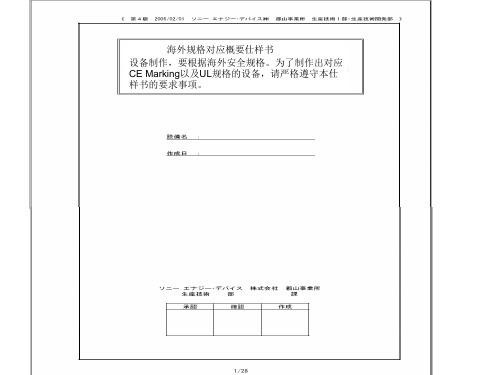
海外规格仕样书第4版(中文)
4.在机铭板上标示出以下内容 ・制造者名 ・制造年月 ・形式以及model编号 ・定格电源电压(电压、位相、周波数、最大负荷电流、etc) 在电源上不可以用「AC200V」表示,而要用「~200V」表示 ・气压(定格压力) ・原产地表示(MADE IN JAPAN等) 注)FA标准机铭板: 4—710—156—01(大—11) 带孔、by三立产业 EN60204 UL1740
8.盖子、马达框架、trans core、电装品筐体、以及接续管等的金属部, 如果和地线或金属接触,会导致和物品本身的导通。
EN60204、UL1740
7/28
要求事项
1.电源切断装置要使用得到认可的漏电断路器、自动断路器、线路保护器 EN60204、UL1740 2.主断路器的定格要遵循以下事项。 EN60204、UL1740 a)电流容量:最大负荷电流的115%以上,或者使用的导线的要求容许电流以下 (14配线以及电路——参照17) b)切断容量:在机器上使用的马达中,最大马达的 rotor rock电流+其他装置的 最大负荷电流以上 3.电力引入线(一次电源)要直接和断路器连接 EN60204、UL1740 4.电源切断装置遵循一下事项。 EN60204、UL1740 (a)安装把手,方便从外部操作 (b)把手的中心高度在0.6~1.9以内 (c)要有OFF锁定机能.(可以上锁的构造) (d)门关上时要有ON/OFF的明确指示 (e)ON/OFF可以用「O」也可以用「I」来表示 (f)接地导线以外所有的相要同时切断 (g)主断路器上如果没有OFF锁定机能,要在负荷侧设定带钥匙的主开关。
贵社 check
本社 check
备注
① 外 观 以 及 构 造 的 规 定
4/28
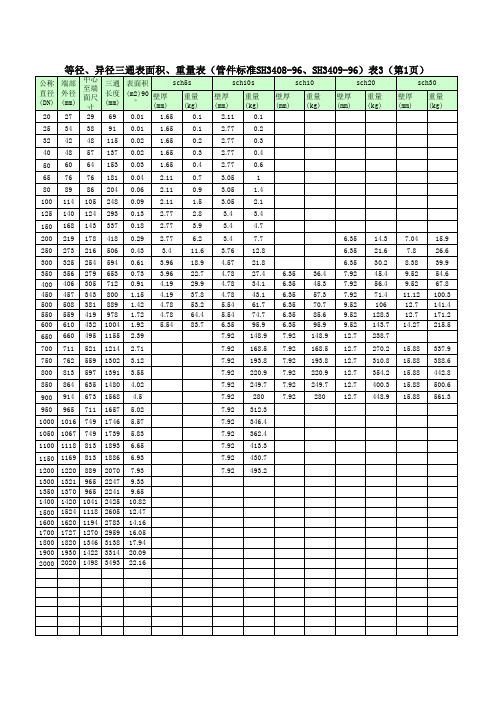
石化三通重量和表面积明细表
7.92 280 7.92 280 12.7 448.9 15.88 561.3
950 965 711 1657 5.02
7.92 312.3
1000 1016 749 1746 5.57
7.92 346.4
1050 1067 749 1739 5.83
7.92 362.4
1100 1118 813 1893 6.65
800 813 597 1391 3.55
7.92 220.9 7.92 220.9 12.7 354.2 15.88 442.8
850 864 635 1480 4.02
7.92 249.7 7.92 249.7 12.7 400.3 15.88 500.6
900 914 673 1568 4.5
sch20
壁厚 (mm)
重量 (kg)
sch30
壁厚 (mm)
重量 (kg)
20 27 29 69 0.01 1.65
0.1
2.11
0.1
25 34 38 91 0.01 1.65
0.1
2.77
0.2
32 42 48 115 0.02 1.65
0.2
2.77
0.3
40 48 57 137 0.02 1.65
12.7 270.2
750 762 559 1302 3.12 9.52 233 9.52 233
12.7 310.8
800 813 597 1391 3.55 9.52 265.5 9.52 265.5
12.7 354.2
850 864 635 1480 4.02 9.52 300.1 9.52 300.1
7.92 413.3
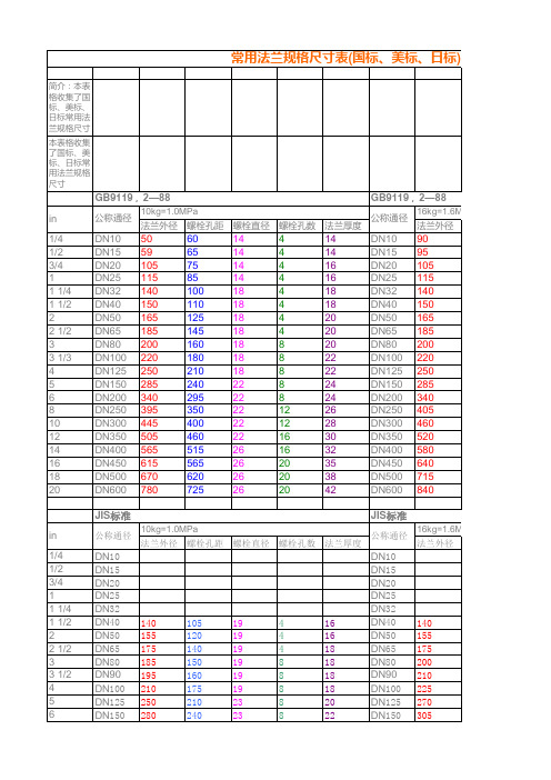
常用法兰规格尺寸表(国标、美标、日标)
16 16 18 18 18 18 20 22 22 24 24 26 28
DN10 DN15 DN20 DN25 DN32 DN40 DN50 DN65 DN80 DN90 DN100 DN125 DN150 DN200 DN250 DN300 DN350 DN400 DN450 DN500
140 155 175 200 210 225 270 305 350 430 480 540 605
标、日标)
,2—88
16kg=1.6MPa 螺栓孔距 螺栓直径 螺栓孔数 法兰厚度
60 65 75 85 100 110 125 145 160 180 210 240 295 355 410 470 525 585 650 770
14 14 14 14 18 18 18 18 18 18 18 22 22 26 26 26 30 30 33 36
19 22 22 22 22 22 22 25 29 32 32 35
4 8 8 8 8 8 12 12 16 16 20 20
18 18 20 22 24 26 28 30 34 36 40 46
11 M10
14 M12
18 (19) M16
22 (23) M20
26 (28) M24
30 (31) M27
10kg=1.0MPa 16kg=1.6MPa 公称通径 公称通径 法兰外径 螺栓孔距 螺栓直径 螺栓孔数 法兰厚度 法兰外径
DN10 DN15 DN20 DN25 DN32 DN40 DN50 DN65 DN80 DN100 DN125 DN150 DN200 DN250 DN300 DN350 DN400 DN450 DN500 DN600 JIS标准
LM4040DEM3-5.0手册
LM4040
Ordering Information Industrial Temperature Range (−40˚C to +85˚C)
Reverse Breakdown
Voltage Tolerance at
25˚C and Average Reverse Breakdown Voltage Temperature Coefficient ±0.1%, 100 ppm/˚C max (A grade)
j Low output noise (10 Hz to 10 kHz)
j Wide operating current range j Industrial temperature range j Extended temperature range j Low temperature coefficient
The LM4040 utilizes fuse and zener-zap reverse breakdown voltage trim during wafer sort to ensure that the prime parts have an accuracy of better than ±0.1% (A grade) at 25˚C. Bandgap reference temperature drift curvature correction and low dynamic impedance ensure stable reverse breakdown voltage accuracy over a wide range of operating temperatures and currents.
±0.2%, 100 ppm/˚C max (B grade)
Parker Hannifin NH-94XXX球缸保护器材料安全数据表说明书
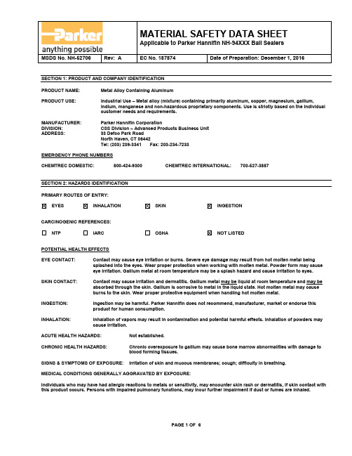
MSDS No. NH-52706 Rev: A EC No. 187874 Date of Preparation: December 1, 2016SECTION 1: PRODUCT AND COMPANY IDENTIFICATIONPRODUCT NAME: Metal Alloy Containing AluminumPRODUCT USE: Industrial Use – Metal alloy (mixture) containing primarily aluminum, copper, magnesium, gallium,indium, manganese and non-hazardous proprietary components. Use is strictly based on the individualcustomer needs and requirements.MANUFACTURER: Parker Hannifin CorporationDIVISION: CSS Division – Advanced Products Business UnitADDRESS: 33 Defco Park RoadNorth Haven, CT 06442Tel: (203) 239-3341 Fax: 203-234-7233EMERGENCY PHONE NUMBERSCHEMTREC DOMESTIC: 800-424-9300 CHEMTREC INTERNATIONAL: 703-527-3887SECTION 2: HAZARDS IDENTIFICATIONPRIMARY ROUTES OF ENTRY:EYES INHALATION SKIN INGESTIONCARCINOGENIC REFERENCES:NTP IARC OSHA NOT LISTEDPOTENTIAL HEALTH EFFECTSEYE CONTACT: Contact may cause eye irritation or burns. Severe eye damage may result from hot molten metal being splashed into the eyes. Wear proper protection when working with molten metal. Powder form may causeeye irritation. Gallium metal at room temperature may be a splash hazard and cause irritation to eyes. SKIN CONTACT: Contact may cause irritation and dermatitis. Gallium metal may be liquid at room temperature and may be absorbed through the skin. Gallium is corrosive to metal in the liquid state. Hot molten metal may causeburns to the skin. Wear proper protective equipment when handling hot molten metal.INGESTION: Ingestion may be harmful. Parker Hannifin does not recommend, manufacturer, market or endorse this product for human consumption.INHALATION: Inhalation of vapors may result in contamination and potential harmful effects. Inhalation of powders may cause irritation.ACUTE HEALTH HAZARDS: Not established.CHRONIC HEALTH HAZARDS: Chronic overexposure to gallium may cause bone marrow abnormalities with damage toblood forming tissues.SIGNS & SYMPTOMS OF EXPOSURE: Irritation of skin and mucous membranes; cough; difficulty in breathing.MEDICAL CONDITIONS GENERALLY AGGRAVATED BY EXPOSURE:Individuals who may have had allergic reactions to metals or sensitivity, may encounter skin rash or dermatitis, if skin contact with this product occurs. Persons with impaired pulmonary functions, may incur further impairment if dust or fumes are inhaled.MSDS No. NH-52706 Rev: A EC No. 187874 Date of Preparation: December 1, 2016SECTION 3: COMPOSITION / INFORMATION ON INGREDIENTS(mg/m3) TLV-STEL(mg/m3) COMPONENT: CAS NO. % WT PEL (mg/m3) TLV-TWAAluminum 7429-90-5 45-85 15 10N.E. N.E. N.E. Gallium 7440-55-30.5-10.50.2-2.0 0.1 0.1 N.E. Indium 7440-74-6Copper 7440-50-82.2-5.4 1 1Magnesium 7439-95-4 0.5-5.5 N.E. 10Manganese 7439-96-5 0.1-1.5 5 0.2 3PROPRIETARY 0.3 MAX. N.E. N.E. N.E.PROPRIETARY 0.2 MAX. N.E. N.E. N.E.SECTION 3 NOTESThis product in not considered to constitute a physical or health hazard in the form it is sold. Subsequent operations such as abrading, melting, welding, cutting or processing in any other fashion may produce potentially hazardous dust or fumes which canbe inhaled, swallowed, or come into contact with skin or eyes.N.E. = Not EstablishedSECTION 4: FIRST AID MEASURESEYE CONTACT: Hold eyelids apart and flush eyes with plenty of water for at least 15 minutes. Seek medical attention if irritation persists.SKIN CONTACT: Remove contaminated clothing. Wash affected area with soap and water. Wash clothing before reuse. If irritation persists, obtain medical attention.INGESTION: If patient is conscious, ONLY induce vomiting as directed by trained personnel. NEVER give anything by mouth to an unconscious person. Seek medical attention immediately.INHALATION: Remove to fresh air. If not breathing, give artificial respiration or oxygen by trained personnel. Seeimmediate medical attention.SECTION 5: FIRE-FIGHTING MEASURESFLASH POINT: Not Applicable FLAMMABLE LIMITS: NonflammableAUTOIGNITION TEMPERATURE: Not EstablishedEXTINGUISHING MEDIA: Product will not burn in the solid state. Product dust and powder may burn under someconditions. Use extinguishers appropriate for the surrounding fire conditions. DO NOTDIRECT WATER AT OR ONTO MOLTEN METAL – IT WILL EXPLODE.SPECIAL FIRE FIGHTING PROCEDURES: Firefighters must wear NIOSH approved self-contained breathing apparatus and fullprotective clothing.MSDS No. NH-52706 Rev: A EC No. 187874 Date of Preparation: December 1, 2016SECTION 6: ACCIDENTAL RELEASE MEASURESSMALL OR LARGE SPILL: In solid form this material poses no special clean-up problems. Use normal clean up procedures; wet sweeping or HEPA vacuum is recommended for cleanup of dust or powder. Do not use compressed airfor cleaning.SECTION 7: HANDLING AND STORAGEHANDLING AND STORAGE: Product should be kept dry.HANDLING PRECAUTIONS: Avoid contact with sharp edges or heated material. Hot and cold material is not visually different and will not present a warning color change. Exercise caution in instances where material may be hot. SECTION 8: EXPOSURE CONTROLS/PERSONAL PROTECTIONVENTILATION : Local exhaust recommended when cutting, grinding or melting or any other operation wheredust or fumes are created.RESPIRATORY PROTECTION: Not normally required. Use an appropriate NIOSH approved respirator if airborne dustconcentrations exceed the OSHA, PEL or ACGIH, TLV.EYE PROTECTION: Safety glasses are recommended.SKIN PROTECTION: Protective gloves are recommended to prevent mechanical irritation.OTHER PROTECTIVE CLOTHING OR EQUIPMENT: Eye wash stations should be readily available in areas of use or handling. WORK HYGIENIC PRACTICES: If the operation generates dust or fumes, exposure to airborne materials should be determinedby having air samples taken in the employees breathing zone and work area.EXPOSURE GUIDELINES: Not established for product as a whole. Refer to Sections 2 & 3.SECTION 9: PHYSICAL AND CHEMICAL PROPERTIESAPPEARANCE: Grey solid metalODOR: Normally none. Slight metallic odor when wet.MELTING POINT: Not established (>850°F)g/cm3DENSITY: 2.70-2.90SOLUBILITY IN WATER: Generally insoluble. Under certain conditions, product may react with water to form aluminumhydroxide and low quantities of evolved hydrogen gas.PERCENT SOLIDS BY WEIGHT: 100%PERCENT VOLATILE BY WEIGHT: Essentially zero.MSDS No. NH-52706 Rev: A EC No. 187874 Date of Preparation: December 1, 2016SECTION 10: STABILITY AND REACTIVITYSTABILITY: Stable in dry air. May tarnish slightly in moist air.CONDITIONS TO AVOID: Conditions which create dust or fumes.INCOMPATIBILE MATERIALS: Reaction with concentrated acids or bases (e.g. sodium hydroxide, potassium hydroxide, sulfuricacid and hydrochloric acid) with a pH less than 5.0 or greater than 11.0 may liberate large quantitieshydrogen gas.HAZARDOUS DECOMPOSITION OR BY-PRODUCTSEvolved hydrogen in confined areas may pose an explosion hazard (see directly above and refer to Section 14). Do not store wet product in confined (i.e. sealed) containers. Potentially hazardous oxides of metals may be produced when product is heated or in a molten state.HAZARDOUS POLYMERIZATION: Will not occur.SECTION 11: TOXICOLOGICAL INFORMATIONTOXICOLOGICAL INFORMATION: There is no information on the toxicity of this alloy. Under normal use of the solid form of this material there are no known health hazards. Welding, grinding or any process creating dust, fumes or oxides may cause hazardous levels of certain elements, as addressed in Sections 2 & 3.SECTION 12: ECOLOGICAL INFORMATIONECOLOGICAL INFORMATION: In solid form this material poses no special environmental problems. Metal powder or dust mayimpact air or water quality. Emissions, spills and releases to the environment should becontrolled immediately.SECTION 13: DISPOSAL CONSIDERATIONSWASTE DISPOSAL METHOD: Due to its high intrinsic value, this material should be reclaimed. Contact a commercial reclaimerfor recycling. Otherwise, dispose of in accordance with all Federal, State and Local environmentalregulations.MSDS No. NH-52706 Rev: A EC No. 187874 Date of Preparation: December 1, 2016SECTION 14: TRANSPORT INFORMATIONGROUND TRANSPORTATIOND.O.T. SHIPPING NAME: Not regulated TECHNICAL SHIPPING NAME: Metal AlloyD.O.T. HAZARD CLASS: None UN SHIPPING NUMBER: NonePRODUCT RQ: None PACKING GROUP: NoneAIR TRANSPORTATIONICAO-TI AND IATA-DGR: Not regulated in solid formA representative sample of this composite metal alloy was selected and tested per Section 33.4 of the UN Manual of Tests and Criteria, 5th Revised Edition - “Substances Which In Contact with Water Emit Flammable Gases”. Test results indicate that reaction of this material with water DOES NOT produce spontaneous ignitable gas and DOES NOT exceed the rate of gas emission required to be considered a hazardous substance in accordance with Class 4, Division 4.3 (refer to Section 2.4.4 of the UN Model Regulations and Parker Hannifin APBU Report No. NH-52695).This metal alloy, having a melting point in excess of 850°F (454°C), will not become liquid during normal transport conditions. In solid form it is considered to be non-corrosive to both aluminum and steel alloys. Therefore, the material is not considered to be a hazardous substance in accordance with Class 8 (refer to sections 2.8.1 and 2.8.2 of the UN Model Regulations).MSDS No. NH-52706 Rev: A EC No. 187874 Date of Preparation: December 1, 2016 SECTION 15: REGULATORY INFORMATIONHMIS Ratings Health = 2 Flammability = 1 Physical Hazard = 0 Personal Protection = E NFPA Ratings Health = 2 Flammability = 1 Instability = 1 Special Notice = N/AOSHA STATUSNo specific regulations. The Hazard Communication Standard of the Occupational Safety and Health Administration, 29 CFR 1910.1200 considers components of this product a Hazardous Substance.TSCA STATUSThis product is an alloy (mixture). Components of this product are listed on the TSCA Chemical Substance Inventory of Existing Chemical Substances.SARA TITLE IIIThe constituents of this alloy (mixture) contain hazardous substances, above one (1) percent, and are subject to the reporting requirements of section 313 of the Emergency Planning and Community Right to Know Act of 1986 and 40CFR372.CANADA – WHMIS DISCLOSURE LISTMaterial does not fall into a Subdivision, or Division as defined by any Section of SOR/DORS/88-66.EUROPEAN UNION – RISK PHRASE: N/ASECTION 16: OTHER INFORMATIONPREPARED BY: Parker Hannifin CorporationComposite Sealing Systems DivisionAdvanced Products Business UnitEnvironmental Health & Safety Department33 Defco Park RoadNorth Haven, CT 06473DISCLAIMERThe information above is believed to be accurate and represents the best information currently available to Parker Hannifin. However, we make no warranty of merchantability or any other warranty, express or implied, with respect to such information, and we assume no liability resulting from its use. Users should make their own investigations to determine the suitability of the information for their particular purposes. In no event shall Parker Hannifin be liable for any claims, losses, or damages of any third party or for lost profits or any special, indirect, incidental, consequential or exemplary damages, howsoever arising, even if Parker Hannifin has been advised of the possibility of such damages.。
中外有色金属及其牌号近似对照
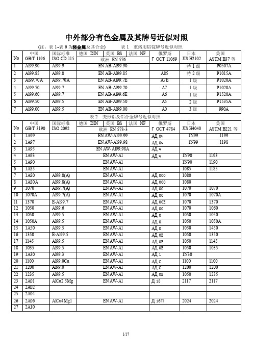
中外部分有色金属及其牌号近似对照
表2 变形铝及铝合金牌号近似对照
表4 原生镁锭牌号近似对照
表5 变形镁及镁合金牌号近似对照
续表5
表8 加工铜牌号近似对照
表10 加工青铜牌号近似对照
表12 铸造铜合金牌号近似对照
表13 锌锭牌号近似对照`
表14 加工锌及锌合金牌号近似对照
表15 压铸锌合金牌号近似对照
表16 压铸锌合金牌号近似对照
表17 锡及锡合金牌号近似对照
表18 铅及铅合金牌号近似对照
表22 铸造钛及钛合金牌号近似对照
表23 钨及其产品名称和牌号
表24 钨板(丝)牌号近似对照
表25 钼及其产品名称和牌号
表26 钼产品名称及牌号近似对照
(注:表27~表35为贵金属及其合金)表27 金锭及纯金(丝)牌号近对照
表29 银及纯银牌号近似对照
表30 银合金牌号近似对照
表31 银粉牌号
表32 海绵铂牌号近似对照
表34 铂合金牌号近似对照
表35 铱粉牌号近似对照
表36 铸造轴承合金牌号近似对照。
nsk轴承后缀代号说明[技巧]
![nsk轴承后缀代号说明[技巧]](https://img.taocdn.com/s3/m/e34cf9fb112de2bd960590c69ec3d5bbfd0adac0.png)
NSK轴承后缀代号说明NS7S是NSK的油脂和油脂封入量的番号.NS7是油脂名NShilube grease,S是其封入量(封入的比例是35%以上).(1)内部结构A——内部设计与标准不同的轴承。
A——角接触球轴承,接触角为30度。
A5——角接触球轴承,接触角为25度。
B——角接触球轴承,接触角为40度。
C——角接触球轴承,接触角为15度。
C——圆锥滚子轴承,接触角为20度。
D——圆锥滚子轴承,接触角为28度。
C,CA(带黄铜实体保持架),CD(带冲压保持架)——高负载调心滚子轴承。
E——高负载圆柱滚子轴承。
H——高负载推力调心滚子轴承。
J——圆锥滚子轴承的外圈滚道的小端径,角度,外圈宽度与ISO规定一致。
(2)材料g——套圈,滚动体为渗碳钢。
H——套圈,滚动体为不锈钢。
(3)保持架M——铜合金实体保持架。
T——合成树脂保持架。
W——冲压保持架。
V——无保持架。
(4)密封圈,防尘盖Z,ZS——一面带钢板防尘盖。
ZZ,ZZS——两面带钢板防尘盖。
D,DU——一面带接触式橡胶密封圈。
DD,DDU——两面带接触式橡胶密封圈。
V——一面带非接触式橡胶密封圈。
VV——两面带非接触式橡胶密封圈。
(5)套圈形状K——圆锥孔,锥度1:12。
K30——圆锥孔,锥度1:30。
E——套圈上有切口或油孔。
E4——外圈上带油槽,油孔。
N——外圈外径带止动槽。
NR——外圈外径带止动槽,止动环。
(6)配合及衬垫DB——背靠背成对安装。
DF——面对面成对安装。
DT——串联成对安装。
+K——外圈带衬垫。
+L——内圈带衬垫。
+KL——内,外圈带衬垫。
H——紧定套的结构代号AH——拆卸套的结构代号HJ——L型档边圈结构代号(7)游隙C1——向心轴承径向游隙,比C2游隙小。
C2——向心轴承径向游隙,比标准游隙小。
CN(省略)——向心轴承径向标准游隙。
C3——向心轴承径向游隙,比标准游隙大。
C4——向心轴承径向游隙,比C3游隙大。
C5——向心轴承径向游隙,比C4游隙大。
DLT404-20073(可编辑)

DLT 404-2007 3DL中华人民共和国电力行业标准DL/T 404-2007代替 DL/T 404-19973.6kV~40.5kV 交流金属封闭开关设备和控制设备Alternating-Current metal-enclosed Switchgear and controlgear for rated voltagesabove 3.6kV and up to and including 40.5kV(IEC 62271-200: 2003 Alternating-Current metal-enclosed switchgear andcontrolgear for rated voltages above 1kV and up to and including 52kV, MOD)2007-12-11发布 2008-06-01 实施中华人民共和国国家发展和改革委员会发布//.DL/T 404-2007目次前言V1 概述.11.1 范围11.2 规范性引用文件. 12 正常和特殊使用条件..23 术语和定义.23.101 开关设备和控制设备 switchgear and controlgear23.102 金属封闭开关设备和控制设备 metal-enclosed switchgear and controlgear 2//0>. //.3.103 功能单元(总装的)functional unit of an assembly23.104 多层multi-tier23.105 运输单元 transport unit 23.106 外壳enclosure 23.107 隔室compartment. 23.108 隔板partition 33.109 隔板的等级 partition class 3//. //.3.110 活门shutter33.111 分隔(导体的)segreation of conductors 33.112 套管bushing33.113 元件component 33.114 主回路(总装的)main circuit of an assembly. 43.115 接地回路 earthing circuit. 43.116 辅助回路 auxiliary circuit 43.117 压力 //. //. 释放装置 pressure relief device 43.118 充流体隔室 fluid-filled compartment 43.119 相对压力 relative pressure 43.120 昀低功能水平(充流体隔室的)minimum functional level of fluid-filled compartments43.121 设计水平(充流体隔室的)design level of fluid-filled compartments 43.122 设计温度(充流体隔室的)design temperature of fluid-filled compartments 43.123 周围空气温度(金属封闭开关设备和控制设备的)ambient air temperature of//. //.metal-enclosed switchgear and controlgear43.124 可移开部件 removable part. 53.125 可抽出部件 withdrawable part. 53.126 工作位置(接通位置)service position connected position. 53.127 接地位置 earthing position 53.128 试验位置(可抽出部件的)test position of a withdrawable part53.129 隔离位置(可抽出部件的)disconnected position of a withdrawable part 53.130 移开位置(可移开部件的)removed position of a removable part53.131 丧失运行连续性类别(LSC)loss of service continuity category LSC. 53.132 内部电弧级开关设备和控制设备(IAC)internal arc classified switchgear and?I?//.DL/T 404-2007controlgear IAC 53.133 防护等级 degree of protection 63.134 额定值 rated value63.135 破坏性放电 disruptive discharge. 64 额定值..64.1 额定电压(Ur)64.2 额定绝缘水平 64.3 额定频率(f )6r4.4 额定电流和温升. 64.5 额定短时耐受电流(I ) 7k4.6 额定峰值耐受电流(IP) 74.7 额定短路持续时间(tk) 74.8 合闸和分闸装置及其辅助和控制回路的额定电源电压(Ua)7 4.9 合闸和分闸装置及其辅助回路的额定电源频率74.10 可控压力系统压缩气源的额定压力74.11 绝缘和/或操作用气体或液体的额定充入水平..75 设计和结构.75.1 对开关设备和控制设备中液体的要求. 85.2 对开关设备和控制设备中气体的要求. 85.3 接地85.4 辅助设备和控制设备 95.5 动力操作. 95.6 储能操作. 95.7 不依赖人力的操作95.8 脱扣器的操作 95.9 低压力和高压力闭锁和监视装置95.10 铭牌. 95.11 联锁装置105.12 位置指示115.13 外壳的防护等级115.14 爬电距离115.15 气体和真空的密封 115.16 液体的密封 115.17 易燃性. 115.18 电磁兼容性(EMC)115.19 X 射线的辐射115.20 腐蚀 115.101 内部故障. 115.102 外壳125.103 隔室135.104 可移开部件155.105 电缆绝缘试验的规定 155.106 对小空气间隙的要求昀 16?II?//.DL/T 404-20076 型式试验..166.1 概述. 166.2 绝缘试验 176.3 无线电干扰电压(r、i、v)试验 19 6.4 回路电阻的测量 196.5 温升试验 206.6 短时耐受电流和峰值耐受电流试验20 6.7 防护等级检验216.8 密封试验 226.9 电磁兼容性试验(EMC)226.10 辅助和控制回路的附加试验. 226.10.3 接地金属部件的电气连续性试验. 22//. //.6.11 真空开断装置 X射线试验程序226.101 关合和开断能力的验证. 226.102 机械试验. 236.103 充气隔室的压力耐受试验和气体状态检测 23 6.104 非金属隔板和活门的试验236.105 防雨试验. 246.106 内部电弧试验 24//. //.7 出厂试验..257.1 主回路的绝缘试验. 257.2 辅助和控制回路的试验 257.3 主回路电阻测量 257.4 密封试验 257.5 设计和外观检查 257.6 机械操作和机械特性试验. 25//. //.7.101 局部放电测量 267.102 充气隔室的压力试验和气体状态测量. 26 7.103 电动、气动和液压装置的辅助装置的试验 26 7.104 现场安装后的试验267.105 现场充流体后的流体状态测量. 268 金属封闭开关设备和控制设备的选用导则..268.1 额定值的选择26//. //.8.2 设计和结构的选择. 278.3 内部电弧等级的选择289 应随订货单、投标书和询问单一起提供的资料.319.101 随订货单和询问单一起提供的资料 319.102 投标时应提供的资料 3210 运输、储存、安装、运行和维修规则..3310.1 运输、储存和安装时的条件. 3310.2 安装 33?III?//.DL/T 404-200710.3 运行 3310.4 维修 3311 安全..3311.101 程序. 3311.102 内部电弧 34附录 A (规范性附录)内部故障??在内部故障引起电弧的条件下金属封闭开关设备和控制设备的试验方法错误!未定义书签。
LM4040DIM3-2.5中文资料
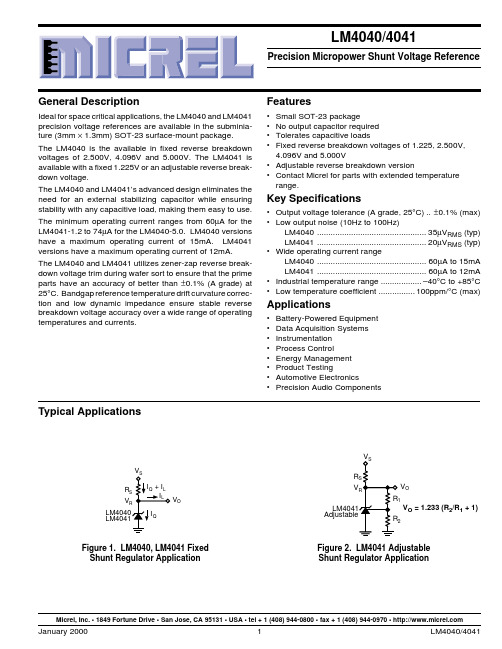
Typical ApplicationsV O V R V V OFigure 2. LM4041 Adjustable Shunt Regulator ApplicationFigure 1. LM4040, LM4041 Fixed Shunt Regulator Application V O = 1.233 (R 2/R 1 + 1)Micrel, Inc. • 1849 Fortune Drive • San Jose, CA 95131 • USA • tel + 1 (408) 944-0800 • fax + 1 (408) 944-0970 • Part Number *Voltage Accuracy,Temp. Coefficient LM4041AIM3-1.2 1.225V ±0.1%, 100ppm/°C LM4041BIM3-1.2 1.225V ±0.2%, 100ppm/°C LM4041CIM3-1.2 1.225V ±0.5%, 100ppm/°C LM4041DIM3-1.2 1.225V ±1.0%, 150ppm/°C LM4041CIM3-ADJ 1.24V to 10V ±0.5%, 100ppm/°C LM4041DIM3-ADJ1.24V to 10V±1.0%, 150ppm/°CPin Configuration–FB +Adjustable Version SOT-23 (M3) PackageTop ViewFixed Version SOT-23 (M3) PackageTop View +–Pin 3 must float orbe connected to pin 2.Part Number *Voltage Accuracy,Temp. Coefficient LM4040AIM3-2.5 2.500V ±0.1%, 100ppm/°C LM4040BIM3-2.5 2.500V ±0.2%, 100ppm/°C LM4040CIM3-2.5 2.500V ±0.5%, 100ppm/°C LM4040DIM3-2.5 2.500V ±1.0%, 150ppm/°C LM4040AIM3-4.1 4.096V ±0.1%, 100ppm/°C LM4040BIM3-4.1 4.096V ±0.2%, 100ppm/°C LM4040CIM3-4.1 4.096V ±0.5%, 100ppm/°C LM4040DIM3-4.1 4.096V ±1.0%, 150ppm/°C LM4040AIM3-5.0 5.000V ±0.1%, 100ppm/°C LM4040BIM3-5.0 5.000V ±0.2%, 100ppm/°C LM4040CIM3-5.0 5.000V ±0.5%, 100ppm/°C LM4040DIM3-5.05.000V±1.0%, 150ppm/°CExample Field Code _ _ A3rd CharacterA = ±0.1%B = ±0.2%C = ±0.5%D = ±1.0%Example FieldCode_ 2 _2nd Character 1 = 1.225V2 = 2.500V 4 = 4.096V 5 = 5.000V A = AdjustableExample: R2C represents Reference, 2.500V,±0.5% (LM4040CIM3-2.5)Note: If 3rd character is omitted, container will indicate tolerance.SOT -23 Package MarkingsExample Field Code R _ _1st CharacterR = ReferenceOrdering InformationAbsolute Maximum RatingsReverse Current.........................................................20mA Forward Current.........................................................10mA Maximum Output VoltageLM4041-Adjustable ...................................................15V Power Dissipation at T A = 25°C (Note 2)................306mW Storage Temperature...............................–65°C to +150°C Lead TemperatureVapor phase (60 seconds)..............................+215°C Infrared (15 seconds)......................................+220°C ESD SusceptibilityHuman Body Model (Note 3).................................2kV Machine Model (Note 3).. (200V)Operating Ratings (Notes 1 and 2)Temperature Range(T MIN ≤ T A ≤ T MAX )..........................–40°C ≤ T A ≤ +85°C Reverse CurrentLM4040-2.5..........................................60µA to 15mA LM4040-4.1..........................................68µA to 15mA LM4040-5.0..........................................74µA to 15mA LM4041-1.2..........................................60µA to 12mA LM4041-ADJ ........................................60µA to 12mA Output Voltage RangeLM4041-ADJ ..........................................1.24V to 10V+Functional DiagramLM4040, LM4041 FixedFunctional Diagram LM4041 Adjustable+LM4040-2.5 Electrical CharacteristicsBoldface limits apply for T A = T J = T MIN to T MAX; all other limits T A = T J = 25°C. The grades A, B, C, and D designate initial Reverse Breakdown Voltage tolerance of ±0.1%, ±0.2%, ±0.5%, and ±1.0 respectively.LM4040AIM3LM4040BIM3LM4040CIM3Symbol Parameter Conditions Typical Units(Note 4)Limits Limits Limits(Limit)(Note 5)(Note 5)(Note 5)V R Reverse Breakdown Voltage I R = 100µA 2.500VReverse Breakdown Voltage I R = 100µA±2.5±5.0±12mV (max) Tolerance±19±21±29mV (max) I RMIN Minimum Operating Current45µA606060µA (max)656565µA (max)∆V R/∆T Average Reverse Breakdown I R = 10mA20ppm/°C Voltage Temperature I R = 1mA151********ppm/°C (max) Coefficient I R = 100µA15ppm/°C (max)∆V R/∆I R Reverse Breakdown Voltage I RMIN≤ I R 1mA0.3mV Change with Operating0.80.80.8mV (max) Current Change 1.0 1.0 1.0mV (max)1mA ≤ I R 15mA 2.5mV0.60.60.6mV (max)8.08.08.0mV (max)Z R Reverse Dynamic Impedance I R = 1mA, f = 120Hz0.3ΩI AC = 0.1 I R0.80.80.9Ω (max)e N Wideband Noise I R = 100µA10Hz ≤ f ≤ 10kHz35µV RMS∆V R Reverse Breakdown Voltage t = 1000hrsLong Term Stability T = 25°C ±0.1°C120ppmI R = 100µALM4040DIM3Symbol Parameter Conditions Typical Units(Note 4)Limits(Limit)(Note 5)V R Reverse Breakdown Voltage I R = 100µA 2.500VReverse Breakdown Voltage I R = 100µA±25mV (max) Tolerance±49mV (max) I RMIN Minimum Operating Current45µA65µA (max)70µA (max)∆V R/∆T Average Reverse Breakdown I R = 10mA20ppm/°C Voltage Temperature I R = 1mA15150ppm/°C (max) Coefficient I R = 100µA15ppm/°C (max)∆V R/∆I R Reverse Breakdown Voltage I RMIN≤ I R 1mA0.3mV Change with Operating 1.0mV (max) Current Change 1.2mV (max)1mA ≤ I R 15mA 2.5mV8.0mV (max)10.0mV (max)Z R Reverse Dynamic Impedance I R = 1mA, f = 120Hz0.3ΩI AC = 0.1 I R 1.1Ω (max)e N Wideband Noise I R = 100µA10Hz ≤ f ≤ 10kHz35µV RMS∆V R Reverse Breakdown Voltage t = 1000hrsLong Term Stability T = 25°C ±0.1°C120ppmI R = 100µALM4040-4.1 Electrical CharacteristicsBoldface limits apply for T A = T J = T MIN to T MAX; all other limits T A = T J = 25°C. The grades A, B, C, and D designate initial Reverse Breakdown Voltage tolerance of ±0.1%, ±0.2%, ±0.5%, and ± 1.0% respectively.LM4040AIM3LM4040BIM3Symbol Parameter Conditions Typical Units(Note 4)Limits Limits(Limit)(Note 5)(Note 5)V R Reverse Breakdown Voltage I R = 100µA 4.096VReverse Breakdown Voltage I R = 100µA±4.1±8.2mV (max) Tolerance±31±35mV (max) I RMIN Minimum Operating Current50µA6868µA (max)7373µA (max)∆V R/∆T Average Reverse Breakdown I R = 10mA30ppm/°C Voltage Temperature I R = 1mA20100100ppm/°C (max) Coefficient I R = 100µA20ppm/°C (max)∆V R/∆I R Reverse Breakdown Voltage I RMIN≤ I R 1mA0.5mV Change with Operating0.90.9mV (max) Current Change 1.2 1.2mV (max)1mA ≤ I R 15mA 3.5mV7.07.0mV (max)10.010.0mV (max)Z R Reverse Dynamic Impedance I R = 1mA, f = 120Hz0.5ΩI AC = 0.1 I R 1.0 1.0Ω (max)e N Wideband Noise I R = 100µA10Hz ≤ f ≤ 10kHz80µV RMS∆V R Reverse Breakdown Voltage t = 1000hrsLong Term Stability T = 25°C ±0.1°C120ppmI R = 100µALM4040CIM3LM4040DIM3Symbol Parameter Conditions Typical Units(Note 4)Limits Limits(Limits)(Note 5)(Note 5)V R Reverse Breakdown Voltage I R = 100µA 4.096VReverse Breakdown Voltage I R = 100µA±20±41mV (max) Tolerance±47±81mV (max) I RMIN Minimum Operating Current50µA6873µA (max)7378µA (max)∆V R/∆T Average Reverse Breakdown I R = 10mA30ppm/°C Voltage Temperature I R = 1mA20100150ppm/°C (max) Coefficient I R = 100µA20ppm/°C (max)∆V R/∆I R Reverse Breakdown Voltage I RMIN≤ I R 1mA0.5mV Change with Operating0.9 1.2mV (max) Current Change 1.2 1.5mV (max)1mA ≤ I R 15mA 3.0mV7.09.0mV (max)10.013.0mV (max)Z R Reverse Dynamic Impedance I R = 1mA, f = 120Hz0.5ΩI AC = 0.1 I R 1.0 1.3Ω (max)e N Wideband Noise I R = 100µA10Hz ≤ f ≤ 10kHz80µV RMS∆V R Reverse Breakdown Voltage t = 1000hrsLong Term Stability T = 25°C ±0.1°C120ppmI R = 100µALM4040-5.0 Electrical CharacteristicsBoldface limits apply for T A = T J = T MIN to T MAX; all other limits T A = T J = 25°C. The grades A, B, C, and D designate initial Reverse Breakdown Voltage tolerance of ±0.1%, ±0.2%, ±0.5%, and ± 1.0% respectively.LM4040AIM3LM4040BIM3Symbol Parameter Conditions Typical Units(Note 4)Limits Limits(Limit)(Note 5)(Note 5)V R Reverse Breakdown Voltage I R = 100µA 5.000VReverse Breakdown Voltage I R = 100µA±5.0±10mV (max) Tolerance±38±43mV (max) I RMIN Minimum Operating Current54µA7474µA (max)8080µA (max)∆V R/∆T Average Reverse Breakdown I R = 10mA30ppm/°C Voltage Temperature I R = 1mA20100100ppm/°C (max) Coefficient I R = 100µA20ppm/°C (max)∆V R/∆I R Reverse Breakdown Voltage I RMIN≤ I R 1mA0.5mV Change with Operating 1.0 1.0mV (max) Current Change 1.4 1.4mV (max)1mA ≤ I R 15mA 3.5mV8.08.0mV (max)12.012.0mV (max)Z R Reverse Dynamic Impedance I R = 1mA, f = 120Hz0.5ΩI AC = 0.1 I R 1.1 1.1Ω (max)e N Wideband Noise I R = 100µA10Hz ≤ f ≤ 10kHz80µV RMS∆V R Reverse Breakdown Voltage t = 1000hrsLong Term Stability T = 25°C ±0.1°C120ppmI R = 100µALM4040CIM3LM4040DIM3Symbol Parameter Conditions Typical Units(Note 4)Limits Limits(Limits)(Note 5)(Note 5)V R Reverse Breakdown Voltage I R = 100µA 5.000VReverse Breakdown Voltage I R = 100µA±25±50mV (max) Tolerance±58±99mV (max) I RMIN Minimum Operating Current54µA7479µA (max)8085µA (max)∆V R/∆T Average Reverse Breakdown I R = 10mA30ppm/°C Voltage Temperature I R = 1mA20100150ppm/°C (max) Coefficient I R = 100µA20ppm/°C (max)∆V R/∆I R Reverse Breakdown Voltage I RMIN≤ I R 1mA0.5mV Change with Operating 1.0 1.3mV (max) Current Change 1.3 1.8mV (max)1mA ≤ I R 15mA 3.5mV8.010.0mV (max)12.015.0mV (max)Z R Reverse Dynamic Impedance I R = 1mA, f = 120Hz0.5ΩI AC = 0.1 I R 1.1 1.5Ω (max)e N Wideband Noise I R = 100µA10Hz ≤ f ≤ 10kHz80µV RMS∆V R Reverse Breakdown Voltage t = 1000hrsLong Term Stability T = 25°C ±0.1°C120ppmI R = 100µALM4040 Typical CharacteristicsTest CircuitVLM4041-1.2 Electrical CharacteristicsBoldface limits apply for T A = T J = T MIN to T MAX; all other limits T A = T J = 25°C. The grades A, B, C, and D designate initial Reverse Breakdown Voltage tolerance of ±0.1%, ±0.2%, ±0.5%, and ± 1.0%, respectively.LM4041AIM3LM4041BIM3LM4041CIM3Symbol Parameter Conditions Typical Units(Note 4)Limits Limits Limits(Limit)(Note 5)(Note 5)(Note 5)V R Reverse Breakdown Voltage I R = 100µA 1.225V Reverse Breakdown Voltage I R = 100µA±1.2±2.4±6mV (max) Tolerance±9.2±10.4±14mV (max) I RMIN Minimum Operating Current45µA606060µA (max)656565µA (max)∆V R/∆T Average Reverse Breakdown I R = 10mA20ppm/°C Voltage Temperature I R = 1mA15±100±100±100ppm/°C (max)Coefficient I R = 100µA15ppm/°C (max)∆V R/∆I R Reverse Breakdown Voltage I RMIN≤ I R 1mA0.7mV Change with Operating 1.5 1.5 1.5mV (max) Current Change 2.0 2.0 2.0mV (max)1mA ≤ I R 15mA 4.0mV6.0 6.0 6.0mV (max)8.08.08.0mV (max) Z R Reverse Dynamic Impedance I R = 1mA, f = 120Hz0.5ΩI AC = 0.1 I R 1.5 1.5 1.5Ω (max)e N Wideband Noise I R = 100µA10Hz ≤ f ≤ 10kHz20µV RMS∆V R Reverse Breakdown Voltage t = 1000hrsLong Term Stability T = 25°C ±0.1°C120ppmI R = 100µALM4041DIM3LM4041EIM3Symbol Parameter Conditions Typical Units(Note 4)Limits Limits(Limit)(Note 5)(Note 5)V R Reverse Breakdown Voltage I R = 100µA 1.225V Reverse Breakdown Voltage I R = 100µA±12±25mV (max) Tolerance±24±36mV (max) I RMIN Minimum Operating Current45µA6565µA (max)7070µA (max)∆V R/∆T Average Reverse Breakdown I R = 10mA20ppm/°C Voltage Temperature I R = 1mA15±150±150ppm/°C (max) Coefficient I R = 100µA15ppm/°C (max)∆V R/∆I R Reverse Breakdown Voltage I RMIN≤ I R 1mA0.3mV Change with Operating 2.0 2.0mV (max) Current Change 2.5 2.5mV (max)1mA ≤ I R 15mA 2.5mV8.08.0mV (max)10.010.0mV (max) Z R Reverse Dynamic Impedance I R = 1mA, f = 120Hz0.3ΩI AC = 0.1 I R 2.0 2.0Ω (max)e N Wideband Noise I R = 100µA10Hz ≤ f ≤ 10kHz35µV RMS∆V R Reverse Breakdown Voltage t = 1000hrsLong Term Stability T = 25°C ±0.1°C120ppmI R = 100µALM4041-Adjustable Electrical CharacteristicsBoldface limits apply for T A = T J = T MIN to T MAX; all other limits T J = 25°C unless otherwise specified (SOT-23, see Note 7),I RMIN≤ I R < 12mA, V REF≤ V OUT≤ 10V. The grades C and D designate initial Reverse Breakdown Voltage tolerance of ±0.5% and±1%, respectively for V OUT = 5V.LM4041CIM3LM4041DIM3Symbol Parameter Conditions Typical Units(Note 4)Limits Limits(Limit)(Note 5)(Note 5)V REF Reference Breakdown Voltage I R = 100µA 1.233VV OUT = 5VReference Breakdown Voltage I R = 100µA±6.2±12mV (max) Tolerance (Note 8)±14±24mV (max) I RMIN Minimum Operating Current45µA6065µA (max)6570µA (max)∆V REF Reference Voltage I RMIN≤ I R 1mA0.7mV/∆I R Change with Operating SOT-23: 1.5 2.0mV (max) Current Change V OUT≥ 1.6V 2.0 2.5mV (max)(Note 7)1mA ≤ I R 15mA2mVSOT-23:46mV (max)V OUT≥ 1.6V68mV (max)(Note 7)∆V REF Reference Voltage Change I R = 1mA–1.3mV/V/∆V O with Output Voltage Change–2.0–2.5mV/V (max)–2.5–3.0mV/V (max)I FB Feedback Current60nA100150nA (max)120200nA (max)∆V REF Average Reference V OUT = 5V/∆T Voltage Temperature I R = 10mA20ppm/°C Coefficient I R = 1mA15±100±150ppm/°C (max) (Note 8)I R = 100µA15ppm/°C (max)Z OUT Dynamic Output Impedance I R = 1mA, f = 120HzI AC = 0.1 I RV OUT = V REF0.3ΩV OUT = 10V2Ω (max)e N Wideband Noise I R = 100µA10Hz ≤ f ≤ 10kHz20µV RMS∆V REF Reference Voltage t = 1000hrsLong Term Stability T = 25°C ±0.1°C120ppmI R = 100µAR S 30kV IN1Hz rateTest CircuitNote 1.Absolute Maximum Ratings indicate limits beyond which damage to the device may occur. Operating Ratings indicate conditions for which thedevice is functional, but do not guarantee specific performance limits. For guaranteed specification and test conditions, see the ElectricalCharacteristics. The guaranteed specifications apply only for the test conditions listed. Some performance characteristics may degrade when the device is not operated under the listed test conditions.Note 2.The maximum power dissipation must be derated at elevated temperatures and is dictated by T JMAX (maximum junction temperature), θJA (junction to ambient thermal resistance), and T A (ambient temperature). The maximum allowable power dissipation at any temperature is PD MAX = (T JMAX – T A )/θJA or the number given in the Absolute Maximum Ratings, whichever is lower. For the LM4040 and LM4041,T JMAX = 125°C, and the typical thermal resistance (θJA ), when board mounted, is 326°C/W for the SOT-23 package.Note 3.The human body model is a 100pF capacitor discharged through a 1.5k Ω resistor into each pin. The machine model is a 200pF capacitor discharged directly into each pin.Note 4.Typicals are at T J = 25°C and represent most likely parametric norm.Note 5.Limits are 100% production tested at 25°C. Limits over temperature are guaranteed through correlation using Statistical Quality Control (SQL)methods.Note 6.The boldface (over temperature limit for Reverse Breakdown Voltage Tolerance is defined as the room temperature Reverse Breakdown Voltage Tolerance ±[(∆V R /∆T)(65°C)(V R )]. ∆V R /∆T is the V R temperature coefficient, 65°C is the temperature range from –40°C to the reference point of 25°C, and V R is the reverse breakdown voltage. The total over temperature tolerance for the different grades follows:A-grade: ±0.75% = ±0.1% ±100ppm/°C × 65°C B-grade: ±0.85% = ±0.2% ±100ppm/°C × 65°C C-grade: ±1.15% = ±0.5% ±100ppm/°C × 65°C D-grade: ±1.98% = ±1.0% ±150ppm/°C × 65°CExample: The A-grade LM4040-2.5 has an over temperature Reverse Breakdown Voltage tolerance of ±2.5 × 0.75% = ±19mV.Note 7.When V OUT ≤ 1.6V, the LM4041-ADJ must operate at reduced I R . This is caused by the series resistance of the die attach between the die (–)output and the package (–) output pin. See the Output Saturation curve in the Typical Performance Characteristics section.Note 8.Reference voltage and temperature coefficient will change with output voltage. See Typical Performance Characteristics curves.LM4040 and LM4041 Electrical Characteristic NotesLM4041 Typical CharacteristicsLM4041 Typical Characteristics* Output Impedance vs. Freq.Test Circuit‡ Large Signal ResponseTest Circuit† Reverse CharacteristicsTest CircuitApplications InformationThe LM4040 and LM4041 have been designed for stableoperation without the need of an external capacitor con-nected between the (+) and (–) pins. If a bypass capacitor is used, the references remain stable.Schottky DiodeLM4040-x.x and LM4041-1.2 in the SOT-23 package have a parasitic Schottky diode between pin 2 (–) and pin 3 (die attach interface connect). Pin 3 of the SOT-23 package must float or be connected to pin 1. LM4041-ADJs use pin 3 as the (–) output.Conventional Shunt RegulatorIn a conventional shunt regulator application (see Figure 1),an external series resistor (R S ) is connected between the supply voltage and the LM4040-x.x or LM4041-1.2 reference.R S determines the current that flows through the load (I L ) and the reference (I Q ). Since load current and supply voltage may vary, R S should be small enough to supply at least the minimum acceptable I Q to the reference even when the supply voltage is at its minimum and the load current is at its maximum value. When the supply voltage is at its maximum and I L is at its minimum, R S should be large enough so that the current flowing through the LM4040-x.x is less than 15mA, and the current flowing through the LM4041-1.2 or LM4041-ADJ is less than 12mA.R S is determined by the supply voltage (V S ), the load and operating current, (I L and I Q ), and the reference ’s reverse breakdown voltage (V R ).R s = (V s – V R ) / (I L + I Q )Adjustable RegulatorThe LM4041-ADJ ’s output voltage can be adjusted to any value in the range of 1.24V through 10V. It is a function of the internal reference voltage (V REF ) and the ratio of the external feedback resistors as shown in Figure 2. The output is found using the equation (1)V O = V REF ´ [ (R2/R1) + 1 ]where V O is the desired output voltage. The actual value of the internal V REF is a function of V O . The “corrected ” V REF is determined by (2)V REF ´ = V O (∆V REF / ∆V O ) + V Ywhere V O is the desired output voltage. ∆V REF / ∆V O is found in the Electrical Characteristics and is typically –1.3mV/V and V Y is equal to 1.233V. Replace the value of V REF ´ in equation (1) with the value found using equation (2).Note that actual output voltage can deviate from that pre-dicted using the typical ∆V REF / ∆V O in equation (2); for C-grade parts, the worst-case ∆V REF / ∆V O is –2.5mV/V and V Y = 1.248V.The following example shows the difference in output voltage resulting from the typical and worst case values of ∆V REF / ∆V O :Let V O = +9V. Using the typical values of ∆V REF /∆V O , V REF is 1.223V. Choosing a value of R1 = 10k Ω, R2 = 63.272k Ω.Using the worst case ∆V REF / ∆V O for the C-grade and D-grade parts, the output voltage is actually 8.965V and 8.946V respectively. This results in possible errors as large as 0.39%for the C-grade parts and 0.59% for the D-grade parts. Once again, resistor values found using the typical value of ∆V REF / ∆V O will work in most cases, requiring no further adjustment.Figure 4. Voltage Level DetectorR1120kR21MR1120k R21M12V Figure 3. Voltage Level DetectorFigure 8. Bidirectional Adjustable Clamp±2.4 to ±6VLM4041-ADJV OUTLM4041-ADJV OUTFigure 7. Bidirectional Adjustable Clamp±18V to ±2.4VIFigure 9. Floating Current DetectorV OUTLM4041-ADJFigure 6. Bidirectional Clamp±2.4VFigure 5. Fast Positive Clamp2.4V + ∆VD1D21N914R3240k R4240kR1LM4041-ADJ1.24V R1I OUT =1µA < I OUT = 100mAI Figure 10. Current SourceFigure 11. Precision Floating Current Detector* D1 can be any LED, V F = 1.5V to 2.2V at 3mA. D1 may act as an indicator. D1 willbe on if I THRESHOLD falls below the threshold current, except with I = O.Package InformationSOT-23 (M3)MICREL INC.1849 FORTUNE DRIVE SAN JOSE, CA95131USATEL + 1 (408) 944-0800 FAX + 1 (408) 944-0970 WEB This information is believed to be accurate and reliable, however no responsibility is assumed by Micrel for its use nor for any infringement of patents or other rights of third parties resulting from its use. No license is granted by implication or otherwise under any patent or patent right of Micrel Inc.© 2000 Micrel Incorporated。
2020年常用法兰规格尺寸表
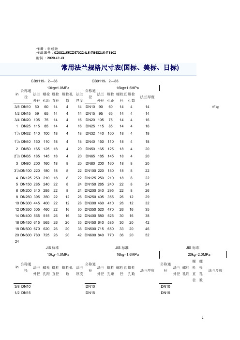
作者:非成败作品编号:92032155GZ5702241547853215475102 时间:2020.12.13GB9119,2—88 GB9119,2—88in 公称通径10kg=1.0MPa公称通径16kg=1.6MPa 法兰外径螺栓孔距螺栓直径螺栓孔数法兰厚度法兰外径螺栓孔距螺栓直径螺栓孔数法兰厚度3/8 DN10 50 60 14 4 14 DN10 90 60 14 4 14 ㎡㎏1/2 DN15 59 65 14 4 14 DN15 95 65 14 4 143/4 DN20 105 75 14 4 16 DN20 105 75 14 4 161 DN25 115 85 14 4 16 DN25 115 85 14 4 1611/4DN32 140 100 18 4 18 DN32 140 100 18 4 1811/2DN40 150 110 18 4 18 DN40 150 110 18 4 182 DN50 165 125 18 4 20 DN50 165 125 18 4 2021/2DN65 185 145 18 4 20 DN65 185 145 18 4 203 DN80 200 160 18 8 20 DN80 200 160 18 8 2031/2DN100 220 180 18 8 22 DN100 220 180 18 8 224 DN125 250 210 18 8 22 DN125 250 210 18 8 225 DN150 285 240 22 8 24 DN150 285 240 22 8 246 DN200 340 295 22 8 24 DN200 340 295 22 8 268 DN250 395 350 22 12 26 DN250 405 355 26 12 2910 DN300 445 400 22 12 28 DN300 460 410 26 12 3212 DN350 505 460 22 16 30 DN350 520 470 26 16 3514 DN400 565 515 26 16 32 DN400 580 525 30 16 3816 DN450 615 565 26 20 35 DN450 640 585 30 20 4218 DN500 670 620 26 20 38 DN500 715 650 33 20 4620 DN600 780 725 26 20 42 DN600 840 770 36 20 5224JIS标准JIS标准JIS标准in 公称通径10kg=1.0MPa公称通径16kg=1.6MPa公称通径20kg=2.0MPa法兰外径螺栓孔距螺栓直径螺栓孔数法兰厚度法兰外径螺栓孔距螺栓直径螺栓孔数法兰厚度法兰外径螺栓孔距螺栓直径螺栓孔数法兰厚度3/8 DN10 DN10 DN10 1/2 DN15 DN15 DN153/4 DN20 DN20 DN201 DN25 DN25 DN2511/4DN32 DN32 DN3211/2DN40 140 105 19 4 16 DN40 140 105 19 4 16 DN40 140 105 19 4 18 2 DN50 155 120 19 4 16 DN50 155 120 19 8 16 DN50 155 120 19 8 18 21/2DN65 175 140 19 4 18 DN65 175 140 19 8 18 DN65 175 140 19 8 20 3 DN80 185 150 19 8 18 DN80 200 , 160 22 8 20 DN80 200 160 23 8 22 31/2DN90 195 160 19 8 18 DN90 210 170 22 8 20 DN90 210 170 23 8 244 DN100 210 175 19 8 18 DN100 225 185 22 8 22 DN100 225 185 23 8 245 DN125 250 210 23 8 20 DN125 270 225 25 8 22 DN125 270 225 25 8 266 DN150 280 240 23 8 22 DN150 305 260 25 12 24 DN150 305 260 25 12 28 8 DN200 330 290 23 12 22 DN200 350 305 25 12 26 DN200 350 305 25 12 30 10 DN250 400 355 25 12 24 DN250 430 380 29 12 28 DN250 430 380 29 12 34 12 DN300 445 400 25 16 24 DN300 480 430 29 16 30 DN300 480 430 29 16 36 14 DN350 490 445 25 16 26 DN350 540 480 32 16 34 DN350 540 480 33 16 40 16 DN400 560 510 27 16 28 DN400 605 540 35 16 38 DN400 605 540 33 16 46 18 DN450 DN450 DN45020 DN500 DN500 DN50024 DN600 DN600 DN600ANSI标准125型ANSI标准150型ANSI标准300型in 公称通径10kg=1.0MPa公称通径16kg=1.6MPa公称通径20kg=2.0MPa法兰外径螺栓孔距螺栓直径螺栓孔数法兰厚度法兰外径螺栓孔距螺栓直径螺栓孔数法兰厚度法兰外径螺栓孔距螺栓直径螺栓孔数法兰厚度3/8 DN10 DN10 DN101/2 DN15 DN15 DN153/4 DN20 DN20 DN201 DN25 DN25 DN2511/4DN32 DN32 DN3211/2DN40 127 98.5 16 4 14.3 DN40 127 98.5 16 4 17.5 DN40 156 114.5 19 4 18 2 DN50 152 120.5 19 4 15.9 DN50 152 121.5 19 4 19.1 DN50 165 127 22 8 18 21/2DN65 178 139.5 19 4 17.5 DN65 178 139.5 19 4 22.3 DN65 190 149 22 8 203 DN80 190 152.5 194 19.1 DN80 190 152.5 19 4 23.9 DN80 210 168 22 8 224 DN100 229 190.5 19 8 23.9 DN100 229 190.5 19 8 23.9 DN100 254 200 22 8 245 DN125 254 216.5 22 8 23.9 DN125 254 216.5 22 8 23.9 DN125 279 235 22 8 266 DN150 279 241.5 22 8 25.4 DN150 279 241.5 22 8 25.4 DN150 318 270 2 2 12 28 8 DN200 343 298.5 22 8 28.6 DN200 343 298.5 22 8 28.6 DN200 381 330 25 12 30 10 DN250 406 362.5 25 12 30.2 DN250 406 362.5 25 12 30.2 DN250 444 387.5 29 16 34 12 DN300 483 432 25 12 31.8 DN300 483 432 25 12 31.8 DN300 521 451 32 16 36 14 DN350 533 476.5 29 12 35 DN350 533 476.5 29 12 35 DN350 584 514.5 32 20 40 16 DN400 597 539.5 29 16 36.6 DN400 597 539.5 29 16 36.6 DN400 648 571.5 3 5 20 46 18 DN450 DN450 DN45020 DN500 DN500 DN50024 DN600 DN600 DN600国标(GB9112—9131—88)管法兰连接尺寸表螺纹法兰突面PN0.6、PN1.0、PN1.6、PN2.5、PN4.0 DN10~ DN150英制系列 欧洲体系GB/T9114-2000突面PN2.0、PN5.0、PN11.0、PN15.0DN15~ DN600英制系列 美洲体系对焊法兰平面、突面、凹凸面、榫槽面 PN0.25、PN0.6、PN1.0、PN1.6、PN2.5、PN4.0、PN6.3、PN10.0、PN16.0DN10~DN3000 英制系列和米制系列欧洲体系GB/T9115.1~GB/T9115.4-2000平面、突面、凹凸面、榫槽面、环连接面PN2.0、PN5.0、PN11.0、PN15.0、PN26.0、PN42.0 DN15~ DN600英制系列 美洲体系带颈平焊法兰平面、突面、凹凸面、榫槽面PN0.6、PN1.0、PN1.6、PN2.5、PN4.0DN10~DN600英制系列和米制系列欧洲体系GB/T9116.1~GB/T9116.4-2000平面、突面、凹凸面、榫槽面、环连接面 PN2.0、PN5.0、PN11.0、PN15.0、PN26.0 DN15~ DN600英制系列美洲体系带颈承插焊法兰突面、凹凸面、榫槽面、环连接面PN2.0、PN5.0、PN11.0、PN15.0、PN26.0 DN15~ DN80英制系列美洲体系 GB/T9117.1~GB/T9117.4-2000对焊环带颈松套法兰突面、环连接面PN2.0、PN5.0、PN11.0、PN15.0、PN26.0、PN42.0DN15~ DN600英制系列美洲体系 GB/T9118.1~GB/T9118.2-2000板式平焊法兰 平面、突面 PN0.25、PN0.6、PN1.0、PN1.6、PN2.5、PN4.0、 DN10~DN2000 英制系列和米制系列欧洲体系GB/T9119-2000对焊环板式松套法兰突面、凹凸面、榫槽面PN1.0、PN1.6、PN2.5、PN4.0、DN10~DN600英制系列和米制系列欧洲体系 GB/T9120.1~GB/T9120.3-2000平焊环板式松套法兰 突面、凹凸面、榫槽面PN0.6、PN1.0、PN1.6、PN2.5、PN4.0DN10~DN600英制系列和米制系列欧洲体系 GB/T9121.1~GB/T9121.3-2000 翻边环板式松套法兰突面PN0.6、PN1.0DN10~DN300英制系列和米制系列欧洲体系GB/T9122-2000法兰盖平面、突面、凹凸面、榫槽面PN0.25、PN0.6、PN1.0、PN1.6、PN2.5、PN4.0、PN6.3、PN10.0、PN16.0DN10~DN2000 欧洲体系GB/T9123.1~GB/T9123.4-2000 平面、突面、凹凸面、榫槽面、环连接面PN2.0、PN5.0、PN11.0、PN15.0、PN26.0、PN42.0DN15~DN600 美洲体系国标钢制管法兰检验标准:GB/T9124-2000国标真空法兰标准(2)图1 固定法兰表1 固定法兰尺寸(mm)公称通径F* B H E* Mjs16CH13X 螺栓D n1016202532405012.217.222.226.234.241.252.2404550557080905560657090100110303540455565758888812126.66.66.66.69990.60.60.60.611166668884444444* 见3.4.2。
10公斤400法兰参数
10公斤400法兰参数全文共四篇示例,供读者参考第一篇示例:10公斤400法兰是一种常用的管道连接件,通常用于连接管道系统中的管道和设备。
它是一种重要的管道配件,具有许多优点,如密封性能好、易安装、可靠性高等特点。
今天我们就来介绍一下关于10公斤400法兰的参数和特点。
让我们来了解一下10公斤400法兰的规格参数。
10公斤400法兰是一种法兰连接件,其法兰压力等级为10公斤,法兰规格为DN400,也就是公称通径为400毫米。
法兰连接的工作压力为10公斤,它通常用于低压管道系统中,适用于水、气体、油品等介质的运输和流动。
10公斤400法兰一般分为板式法兰和对焊法兰两种类型。
板式法兰是将法兰和管道焊接在一起,而对焊法兰是将法兰和管道对接后焊接在一起。
根据不同的工艺要求和使用场合,可以选择不同类型的法兰进行连接。
10公斤400法兰的主要材质一般为碳钢、不锈钢等,具有良好的耐高温、耐腐蚀性能。
选用适当的材质可以确保法兰在长期使用中不受损坏,确保管道系统的正常运行。
除了材质外,10公斤400法兰的密封面也非常重要。
它采用金属密封或软密封,确保了连接处的密封性能。
金属密封可以承受高压和高温环境,而软密封可以适应不同的安装和使用环境,保证了管道系统的密封性能。
在安装时,10公斤400法兰需要通过螺栓将管道和设备连接在一起。
螺栓的数量和规格需要根据法兰的尺寸和使用压力来确定,确保连接处的稳固和密封。
第二篇示例:10公斤400法兰是一种常见的管道连接配件,用于将管道连接在一起以实现流体的传输。
它通常由钢材或铸铁制成,具有较高的强度和耐用性,在工业领域中被广泛应用。
10公斤400法兰的参数包括直径、壁厚、螺栓孔数量和尺寸等。
10公斤表示法兰的压力等级,它代表了法兰在工作条件下所能承受的最大压力,通常以单位“公斤”来表示。
400则表示法兰的尺寸,具体包括法兰的外径、内径和厚度等维度参数。
这些参数决定了法兰的适用范围和承载能力。
10公斤400法兰参数-概述说明以及解释

10公斤400法兰参数-概述说明以及解释1.引言1.1 概述概述在工程领域,10公斤400法兰参数是一种重要的技术规格,通常用于描述连接件的重量和尺寸。
其中,10公斤表示连接件的重量为10公斤,而400法兰则表示连接件的法兰尺寸为400毫米。
这些参数在许多工程项目中都具有关键作用,可以影响到设备的稳定性、安全性和性能表现。
因此,了解和掌握10公斤400法兰参数的含义和重要性对于工程设计和实施具有重要意义。
本文将深入探讨这一技术规格的具体含义和应用价值,以帮助读者更好地理解和运用该参数。
1.2 文章结构文章结构部分应该包括介绍整篇文章的结构安排,让读者对接下来的内容有一个整体的了解。
在这篇关于"10公斤400法兰参数"的文章中,文章结构部分可以简要描述整个文章的组成部分,例如:"文章结构包括引言、正文和结论三个主要部分。
在引言部分,将介绍该主题的概述、文章的结构以及研究目的;接着在正文部分,将详细探讨10公斤和400法兰的含义,并分析它们在参数中的重要性;最后在结论部分,总结分析所得结论并展望未来研究方向,以期对相关领域做出贡献。
"1.3 目的:本文旨在介绍和探讨10公斤400法兰参数的重要性和意义。
通过深入分析10公斤和400法兰的含义,我们将探讨这两个参数在工程领域中的应用和影响。
了解并理解这些参数的重要性,有助于工程师和设计师更好地选择和使用材料,提高产品的性能和质量,从而推动工程技术的发展。
通过本文的阐述,希望读者能够对10公斤400法兰参数有一个更全面的认识,为实际工程项目的应用提供参考和指导。
2.正文2.1 10公斤的含义10公斤是一种重量单位,通常用于衡量物体的重量或质量。
在国际单位制下,1千克等于1000克,而1公斤则等于1000克,因此10公斤相当于10000克。
在日常生活中,10公斤的重量可以被认为是相对较轻的,例如一个标准的水桶大约重约10公斤,而一台小型冰箱的重量也可能在10公斤左右。
法兰规格尺寸表-dn40法兰

常用法兰规格尺寸表(国标、美标、日标)
PL是
板式平焊法兰(PL):
平焊法兰适用于不超过2.5MPa的钢连接.平焊法兰的密封面可以制成光滑式,凹凸式和式三种.光滑式平焊法兰的应用量最大.多用于条件比较缓和的情况下,如非净化、低压。
法兰分类:
1、按(HG)行业标准分:整体法兰(IF)、(Th)、板式平焊法兰(PL)、带颈(WN)、(SO)、(SW)、(PJ/SE)、环松套法兰(PJ/RJ)、(BL(S))、法兰盖(BL)。
2、按石化(SH)行业标准分:螺纹法兰(PT)、对焊法兰(WN)、平焊法兰(SO)、承插焊法兰(SW)、松套法兰(LJ)、法兰盖(不表注)。
3、按(JB)行业标准分:整体法兰、对焊法兰、板式平焊法兰、对焊环板式松套法兰、平焊环板式松套法兰、翻边环板式松套法兰、法兰盖。
4、按国家(GB)标准分:整体法兰、螺纹法兰、对焊法兰、带颈平焊法兰、带颈承插焊法兰、对焊环带颈松套法兰、板式平焊法兰、对焊环板式松套法兰、平焊环板式松套法兰、翻边环板式松套法兰、法兰盖。
回流管参数表

回流管参数表回流管参数表回流管是一种用于石油和天然气开采过程中的重要设备,它起到了控制流体流动和分离液体与气体的作用。
在设计和选择回流管时,需要考虑多个参数以确保其正常运行和高效性能。
下面是一个全面的回流管参数表,包括各个参数的定义、单位以及常见取值范围。
1. 直径(Diameter)- 定义:回流管的内径或外径- 单位:英寸(in)- 常见取值范围:2-10 in2. 厚度(Thickness)- 定义:回流管壁的厚度- 单位:英寸(in)- 常见取值范围:0.1-0.5 in3. 长度(Length)- 定义:回流管的长度- 单位:英尺(ft)- 常见取值范围:10-100 ft4. 材料(Material)- 定义:回流管的制造材料- 常见材料:a) 碳钢(Carbon Steel)b) 不锈钢(Stainless Steel)c) 高合金钢(High-Alloy Steel)5. 工作压力(Working Pressure)- 定义:回流管所能承受的最大压力- 单位:兆帕(MPa)- 常见取值范围:10-100 MPa6. 工作温度(Working Temperature) - 定义:回流管所能承受的最高温度- 单位:摄氏度(℃)- 常见取值范围:-20~150 ℃7. 流体密度(Fluid Density)- 定义:回流管内流体的密度- 单位:千克/立方米(kg/m³)- 常见取值范围:600-2000 kg/m³8. 流量(Flow Rate)- 定义:通过回流管的液体或气体的流量 - 单位:立方米/小时(m³/h)- 常见取值范围:10-1000 m³/h9. 分离效率(Separation Efficiency)- 定义:回流管对液体和气体的分离效果 - 单位:%(百分比)- 常见取值范围:80-99%10. 阻力损失(Pressure Drop)- 定义:液体或气体在通过回流管时产生的压力降低- 单位:帕斯卡(Pa)或兆帕/米(MPa/m)- 常见取值范围:100-1000 Pa或0.1-1 MPa/m11. 腐蚀抗性(Corrosion Resistance)- 定义:回流管对腐蚀的抵抗能力- 常见等级:a) 高抗腐蚀(Highly Corrosion Resistant)b) 中等抗腐蚀(Moderately Corrosion Resistant)c) 低抗腐蚀(Low Corrosion Resistant)12. 环境适应性(Environmental Adaptability)- 定义:回流管对不同环境条件的适应能力- 常见等级:a) 高环境适应性(High Environmental Adaptability)b) 中等环境适应性(Moderate Environmental Adaptability)c) 低环境适应性(Low Environmental Adaptability)13. 安装方式(Installation Method)- 定义:回流管的安装方式- 常见方式:a) 水平安装(Horizontal Installation)b) 垂直安装(Vertical Installation)14. 连接方式(Connection Type)- 定义:回流管的连接方式- 常见方式:a) 螺纹连接(Threaded Connection)b) 焊接连接(Welded Connection)15. 表面处理(Surface Treatment)- 定义:回流管表面的处理方式- 常见处理:a) 砂光(Sandblasting)b) 镀锌(Galvanizing)c) 涂漆(Painting)以上是一个全面的回流管参数表,包括了直径、厚度、长度、材料、工作压力、工作温度、流体密度、流量、分离效率、阻力损失、腐蚀抗性、环境适应性、安装方式、连接方式和表面处理等参数。
截止阀重量参考明细表

J41W-6T
波纹管式截止阀
WJ41W-6P
波纹管式截止阀
WJ41H-6C
低温截止阀
DJ44Y-6P
直流式衬胶截止阀
J45J-6
波纹管式截止阀
WJ61W-6P
内螺纹截止阀
J11X-10
截止阀
J41W-10T
截止阀规格与重量表
名 称 型 号 规格 DN mm 100 15 20 25 32 40 50 65 80 100 125 150 15 20 25 32 40 50 65 15 20 25 32 40 50 65 15 20 25 32 40 50 65 15 20 25 32 40 50 65 15 20 25 32 40 50 65 15 20 25 40 压力 PN Mpa 1.0 1.0 1.0 1.0 1.0 1.0 1.0 1.0 1.0 1.0 1.0 1.0 1.6 1.6 1.6 1.6 1.6 1.6 1.6 1.6 1.6 1.6 1.6 1.6 1.6 1.6 1.6 1.6 1.6 1.6 1.6 1.6 1.6 1.6 1.6 1.6 1.6 1.6 1.6 1.6 1.6 1.6 1.6 1.6 1.6 1.6 1.6 1.6 1.6 1.6 1.6 重量 kg 31.57 2.2 2.5 3.6 6 7 11 16 31 42 63 91 0.7 1.3 1.7 2.7 3.8 6 9.3 0.7 1.3 1.7 2.7 3.8 6 11 0.9 1.5 1.9 2.8 4.2 6 11.2 0.9 1 1.8 2.8 4 5 8.9 0.9 1 1.8 2.8 4 5 8.9 0.75 0.87 1.25 5.5
内螺纹截止阀
J11F-16R
截止阀
不锈钢法兰规格表

(无锡灏艺合金制品有限公司133-8224-9118 )常用法兰规格尺寸表(国标)
表二(无锡灏艺合金制品有限公司133-8224-9118 )不锈钢法兰规格尺寸表
PL
SO WN IF SW
法兰类型及密封面类型
i 「P 么么嫁丁何刃
村昱弦兰崙
CBL CS ))
港兰类樂図其世号
法兰类型代号 法兰类型
板式平焊法兰 带颈平焊法兰 带颈对焊法兰 整体法兰
承插焊法兰
<30?
帶知对怦逹益
(WN )
栓比平坤铁兰
<PL>
I
<7li}
(J
F )
汞战郵法兰
tsw )
(PJZSEJ
叩坤环城霖洸茎
<PJ/RJ}
法兰■
tBU
PJ/SE 对焊环松套法兰
PJ/RJ 平焊环松套法兰
BL 法兰盖
BL(S) 衬里法兰盖
怯兰的豁封面型式茂丼优号医兰国密轉晤媒式包猛:离面、凹面f凸血,轄廊/确面、
全平卿和环歪接面.
北向(RF)
抻U/増砌:T6
凹而/凸厲(MFM) 蜚平曲(FF>
sfiiisan <KJ)
童封充型武星商代号密时吊型式及代寻。
