HFM-1007中文资料
Spectrum 安装维护手册(HLY1007)资料
FTIR SPECTROMETERSpectrum 100/100N安装维护手册注:本文系由仪器附带英文手册编译。
详细内容可参考原文。
2010年7月修订NOTE: 在您安装Spectrum 100/100N之前. 阅读以下警示信息.●电气方面Spectrum 100/100N可工作在50或60 Hz并且电压范围在100到230 V.(无需调节)Spectrum 100/100N正常的功率消耗为120 VA.线电压漂移必须在10% 正常电压范围内.尽可能不要将Spectrum 100/100N连在有大功率消耗的电路上,如大型电机.尽可能不要使用放电灯、无线收发装置等有大负载或频闪负载的在电路上.总保险 (2AT,250V),同备用保险丝一起装置在后部槽内,连接在火线上.●环境如下环境可以使您的Spectrum 100/100N获得最佳性能:∙Spectrum 100/100N应放置在相对无尘的环境中.∙确认放置的平台不会有震动或机械冲击.∙不要将Spectrum 100/100N或其电脑放置在靠近热源的地方, 如中央热辐射装置.∙不要将Spectrum 100/100N放置在阳光直接照射处,以免过热.∙垂直方向保持至少7 cm (3 inches)空间,便于冷却空气流通.∙确认附近无悬挂物、无水管或水龙头可能泄入Spectrum 100/100N .∙仪器电脑附近区域必须无强烈磁场、直射阳光以及加热或冷却单元及管路.Spectrum 100/100N设计用于在室内使用并且允许正确操作的工作条件如下:环境温度15 ︒C到35 ︒C环境相对湿度最大75% (无冷凝)电脑配置要求:在装机之前,您需要连接好电脑并安装光谱软件.建议电脑不要联网,不要安装杀毒软件,防火墙和其他与仪器无关的软件。
电脑最低配置为:处理器:奔腾 400MHz内存:256MB RAM硬盘:10.0 GB,至少1GB可用空间(NTFS格式)网卡: 10/100 M网卡I/O: 1串口,1并口或USB,SP2(鼠标和键盘)系统:正版Windows XP SP2(NTFS)专业版电脑推荐配置为:处理器:奔腾四 2.8GHz内存:512MB RAM缓存:1MB硬盘:80.0 GB,至少1GB可用空间(NTFS格式)网卡: 10/100 M网卡I/O: 1串口,1并口或USB,SP2(鼠标和键盘)系统:原装正版Windows XP SP2专业版开箱Spectrum 100/100N 由一个银色袋子包裹,以防止冷凝.1. 如果任何部件有缺失或损坏, 请联系您本地的供应商.(内容可能变化)3. Spectrum 100/100N 已经预热到环境温度后, 从银色袋子中取出,放置在实验台上。
FAIRCHILD FQT7N10 100V N-Channel MOSFE 说明书

现货库存、技术资料、百科信息、热点资讯,精彩尽在鼎好!FQT7N10Absolute Maximum Ratings T C= 25°C unless otherwise notedParameterDrain-Source VoltageDrain Current- Continuous (T C = 25°C)- Continuous (T C = 70°C)Drain Current- PulsedGate-Source VoltageSOT-223FQT SeriesGDS(Note 4)(Note 4, 5)(Note 4, 5)(Note 4)Notes:1. Repetitive Rating : Pulse width limited by maximum junction temperature2. L = 26mH, I AS = 1.7A, V DD = 25V, R G = 25 Ω, Starting T J = 25°C3. I SD ≤ 7.3A, di/dt ≤ 300A/µs, V DD ≤ BV DSS, Starting T J = 25°C4. Pulse Test : Pulse width ≤300µs, Duty cycle ≤2%5. Essentially independent of operating temperatureBV DSS Drain-Source Breakdown Voltage V GS = 0 V, I D = 250 µA100----V ∆BV DSS / ∆T J Breakdown Voltage Temperature CoefficientI D = 250 µA, Referenced to 25°C --0.1--V/°C I DSS Zero Gate Voltage Drain Current V DS = 100 V, V GS = 0 V ----1µA V DS = 80 V, T C = 125°C ----10µA I GSSF Gate-Body Leakage Current, Forward V GS = 25 V, V DS = 0 V ----100nA I GSSRGate-Body Leakage Current, ReverseV GS = -25 V, V DS = 0 V-----100nAOn CharacteristicsV GS(th)Gate Threshold Voltage V DS = V GS , I D = 250 µA 2.0-- 4.0V R DS(on)Static Drain-Source On-ResistanceV GS = 10 V, I D = 0.85 A --0.280.35Ωg FSForward TransconductanceV DS = 40 V, I D = 0.85 A--1.85--SDynamic CharacteristicsC iss Input Capacitance V DS = 25 V, V GS = 0 V, f = 1.0 MHz--190250pF C oss Output Capacitance--6075pF C rssReverse Transfer Capacitance--1013pFSwitching Characteristicst d(on)Turn-On Delay Time V DD = 50 V, I D = 7.3 A,R G = 25 Ω--725ns t r Turn-On Rise Time --2460ns t d(off)Turn-Off Delay Time --1335ns t f Turn-Off Fall Time --1950ns Q g Total Gate Charge V DS = 80 V, I D = 7.3 A,V GS = 10 V-- 5.87.5nC Q gs Gate-Source Charge -- 1.4--nC Q gdGate-Drain Charge--2.5--nCDrain-Source Diode Characteristics and Maximum RatingsI S Maximum Continuous Drain-Source Diode Forward Current ---- 1.7A I SM Maximum Pulsed Drain-Source Diode Forward Current---- 6.8A V SD Drain-Source Diode Forward Voltage V GS = 0 V, I S = 1.7 A ---- 1.5V t rr Reverse Recovery Time V GS = 0 V, I S = 7.3 A,dI F / dt = 100 A/µs --70--ns Q rrReverse Recovery Charge--150--nCTRADEMARKSThe following are registered and unregistered trademarks Fairchild Semiconductor owns or is authorized to use and is not intended to be an exhaustive list of all such trademarks.DISCLAIMERFAIRCHILD SEMICONDUCTOR RESERVES THE RIGHT TO MAKE CHANGES WITHOUT FURTHER NOTICE TO ANY PRODUCTS HEREIN TO IMPROVE RELIABILITY, FUNCTION OR DESIGN. FAIRCHILD DOES NOT ASSUME ANY LIABILITY ARISING OUT OF THE APPLICATION OR USE OF ANY PRODUCT OR CIRCUIT DESCRIBED HEREIN;NEITHER DOES IT CONVEY ANY LICENSE UNDER ITS PATENT RIGHTS, NOR THE RIGHTS OF OTHERS.LIFE SUPPORT POLICYFAIRCHILD’S PRODUCTS ARE NOT AUTHORIZED FOR USE AS CRITICAL COMPONENTS IN LIFE SUPPORT DEVICES OR SYSTEMS WITHOUT THE EXPRESS WRITTEN APPROVAL OF FAIRCHILD SEMICONDUCTOR CORPORATION.As used herein:1. Life support devices or systems are devices or systems which, (a) are intended for surgical implant into the body,or (b) support or sustain life, or (c) whose failure to perform when properly used in accordance with instructions for use provided in the labeling, can be reasonably expected to result in significant injury to the user.2. A critical component is any component of a life support device or system whose failure to perform can be reasonably expected to cause the failure of the life support device or system, or to affect its safety or effectiveness.PRODUCT STATUS DEFINITIONS Definition of TermsDatasheet Identification Product Status DefinitionAdvance InformationFormative or In Design This datasheet contains the design specifications for product development. Specifications may change in any manner without notice.PreliminaryFirst ProductionThis datasheet contains preliminary data, andsupplementary data will be published at a later date.Fairchild Semiconductor reserves the right to make changes at any time without notice in order to improve design.No Identification Needed Full ProductionThis datasheet contains final specifications. Fairchild Semiconductor reserves the right to make changes at any time without notice in order to improve design.Obsolete Not In ProductionThis datasheet contains specifications on a product that has been discontinued by Fairchild semiconductor.The datasheet is printed for reference information only.ACEx™Bottomless™CoolFET™CROSSVOLT™DenseTrench™DOME™EcoSPARK™E 2CMOS™EnSigna™FACT™FACT Quiet Series™FAST ®FASTr™FRFET™GlobalOptoisolator™GTO™HiSeC™ISOPLANAR™LittleFET™MicroFET™MICROWIRE™OPTOLOGIC™OPTOPLANAR™PACMAN ™POP™PowerTrench ®QFET™QS™QT Optoelectronics™Quiet Series™SLIENT SWITCHER ®SMART START™Stealth™SuperSOT™-3SuperSOT™-6SuperSOT™-8SyncFET™TinyLogic™UHC™UltraFET ®VCX™。
蔗糖基泡沫碳材料前驱体成形的影响因素研究
第52卷第10期 辽 宁 化 工 Vol.52,No.10 2023年10月 Liaoning Chemical Industry October,2023基金项目: 国家自然科学基金项目(项目编号:U1360204、51304139);辽宁省自然基金项目(项目编号:2019-ZD -0258)。
收稿日期: 2022-10-10蔗糖基泡沫碳材料前驱体成形的影响因素研究王坤,李鑫,乔骞,李印,于洪浩*,孙园润,李年平,邢文鹏,王炳天(沈阳理工大学 材料科学与工程学院,辽宁 沈阳 110159)摘 要: 采用凝胶注模成形法制备蔗糖基泡沫碳前驱体,重点研究单体引发过程及蔗糖基碳前驱体成形过程。
通过凝胶时间测定分析单体的含量、交联剂与单体的配比、引发剂的用量以及聚合反应温度来对凝胶过程的影响,通过弯曲强度测试及扫描电镜分析不同交联剂与单体配比下凝胶注模成形的蔗糖碳前驱体的坯体强度及微观结构。
结果表明:丙烯酰胺质量分数28%,N,N -亚甲基双丙烯酰胺质量分数8.4%,引发剂过硫酸铵质量分数2%,50 ℃的聚合温度下,体系的凝胶时间可以控制在 60~130 s 之间,满足凝胶注模成形所需要的操作时间。
上述单体聚合条件下,添加蔗糖50 g、造孔剂120 mL,制备的前驱体弯曲强度为0.46 MPa,SEM 图像显示前驱体当中的造孔剂颗粒均匀,完整性好,同时蔗糖及凝胶包裹在造孔剂周围,连接强度高。
关 键 词:蔗糖;泡沫碳;前驱体;凝胶注模中图分类号:TB332 文献标识码: A 文章编号: 1004-0935(2023)10-1405-04自1985年以来,新型碳材料例如富勒烯、碳纳米管、多孔碳、石墨烯、碳气凝胶等的研究引起人们的广泛关注[1-4]。
碳材料被称为未来的材料,开发和研究新型功能碳材料意义深远。
泡沫碳材料作为一种新型功能多孔碳材料[5],由碳原子相互堆积而成,部分石墨化的晶体结构使其拥有高比表面 积[6-7]、高孔隙率、低密度[8]的特征,具有高强度[9-10]、低导热[11-12]等优异性能,因此在催化、电化学、工业处理、航空航天等方面都获得一定的关注[13]。
HFM-100G双级真空滤油机
HFM-100G高效双级真空滤油机技术资料一、设备性能及用途介绍:1、能快速脱除绝缘油液(包括:变压器油、互感器油、开关油等)中所含的颗粒杂质、粉尘、油泥与沉淀物、微量水分等,提高油液的绝缘性能;2、能有效脱除绝缘油液经长期使用所产生的乙炔、氢气、甲烷等油液中的有害气体,使经设备处理后的油液中乙炔、氢气、甲烷等含量为零;3、特别适合于现场对220KV及以上大型变压器进行抽、注油处理,并能对充油电气设备进行真空热油干燥;在油处理好后,可保持真空对变压器进行真空注油;同时能对变压器进行抽真空、热油循环干燥;4、能够满足安装或检修现场对变压器本体或其它密闭容器进行真空干燥及真空注油处理;并同时完成对变压器所使用过的油液进行在线脱水、脱气及除杂处理,从而延长油液的使用周期及使用寿命;5、广泛适用于发电厂、变电站、电力公司、供电所、变压器生产厂、冶金、石化、机械、交通、铁路等各行业用绝缘油液的快速深度净化处理,特别适合于现场对220KV及以上大型充油电气设备对新油及运行多年的旧绝缘油的净化处理。
二、设备特点:1、该系列高效真空滤油机完全按《真空净油机验收及使用维护导则》电力行业标准DL/T521-2004及《真空净油机》机械行业标准JB/T 5285-2008标准进行设计、制作及验收。
它集油液的精密过滤、高效脱水、脱气、提高油液绝缘强度、降低酸值、真空立体短程薄膜蒸发技术和电气控制系统于一体,操作简单、运行安全、可靠。
能有效保证用油设备正常运行,避免事故发生。
2、ZLA系列高效双级真空滤油机真空系统采用大排量的真空泵与大抽气速率的萝茨组成的真空机组对系统进行抽真空,使系统长期保持在一个极低的真空状态下(极限真空度≤5Pa,工作真空度≤80Pa)工作,使经设备一次过滤后的油液击穿电压提高 30KV 以上,大大缩短了油液处理期,减少一般普通滤油机因多次加热过滤导致油质老化的危害。
3、独特的脱水脱气系统。
采用国际领先的短程薄膜蒸发技术与三维立体闪蒸技术、真空脱水脱气技术结合于一体,能高效快速脱除绝缘油液中的水分及气体(乙炔、氢气、甲烷等),提高绝缘油液的耐压强度和油液品质,系统免维护。
eh系统介绍1007

高压抗燃油电液控制系统(EH系统)上海茂晟电站机械有限公司二00年七月一说明:因茂晟提供的产品跨度历经近二十年,涉及主打产品的种类及改型均各异。
讲义内的相关内容和实物照片可能大部分与用户实际现场设备有差异,但EH系统的原理及应用基分与用户实际现场设备有差异但本相同。
照片可能是茂晟的新产品,可能是设备维修前的照片,一照片可能是茂晟的新产品可能是设备维修前的照片部分为茂晟用户的现场照片。
汽轮机数字式电液控制系统汽轮机数字式电液控制系统(DEH系统)是电站汽轮发电机组不可或缺的重要组成部分,是汽轮机启动、停止、正常运行和事故工况下的调节控制器。
DEH系统通过控制汽轮机主汽门和调故的调节控制系统通过控制汽轮机主汽门和调节汽门的开度,实现对汽轮发电机组的转速、负荷、压力等的控制。
控制汽轮机数字式电液控制系统分为计算机控制系统和液压控制系统两大部分。
其中计算机控制系统用于实现DEH的各种功能并发出指令使各蒸汽阀门动作,液压控制系统(EH系统)用于接收计算机控制系统的指令并驱动各蒸汽阀门动作。
EH系统的组成EH系统是汽轮机数字式电液控制系统--DEH中的一个重要部分,它主要由供油系统、执行机构和危急遮断系统三大部分组成。
•供油系统是一个EH油贮存和处理中心,并向EH系统提供稳定的高压油,以此来驱动执行机构;附图是目前电厂行的典型的汽轮机高压抗燃油以此来驱动执行机构;附图是目前电厂运行的典型的汽轮机高压抗燃油纯电调EH系统液压原理图;•执行机构响应从DEH送来的电指令信号,以调节汽轮机各蒸汽阀开度。
送来的电指令信号以调节汽轮机各蒸汽阀开度•危急遮断系统是由汽轮机的遮断参数所控制,当这些参数超过其运行限制值时,该系统就关闭全部汽轮机蒸汽进汽阀门,或只关闭调节汽阀,制值时该系统就关闭全部汽轮机蒸汽进汽阀门或只关闭调节汽阀以保证汽轮机正常安全运行。
供油装置供油装置的主要功能是提供执行机构所需要的液压油及压力,同时保持液压油的正常理化特性和运行特性供油装置由以下部套组成时保持液压油的正常理化特性和运行特性。
UL_1007电子线说明
UL1007电子线
UL1007电子线,英文为:ELECTRICWIRE1007,是指美国UL认证下的一种型号,目前,该线主要用在弱电工程,如电子科技、电器设备、收银机、计时器、医疗仪器、电器设备、手机、数码相机、机顶盒、复印机、传真机、仪器仪表、电源、充电器、马达、音响、显示器、空调、冰箱、医疗设备、教学设备、玩具、汽车、家用电器以及电路板等产品的连接领域。
AWG是美国导线规格,美国区分导线直径的标准又称B&S线程(即Brown&Sharps线程)铜线直径通常以AWG作为单位进行测量。
AWG前面的数值(如24AWG、26AWG)表示导线形成最后直径前所要经过的孔的数量,数值越大,导线经过的孔就越多,导线的直径也就越小。
粗导线具有更好的物理强度和更低的电阻,但是导线越粗,制作电缆需要的铜就越多,价格就会越贵。
电缆设计的挑战在于使用尽可能小直径的导线,减小成本和安装复杂性,同时还要保证在必要电压和频率之下实现导线的最大容量。
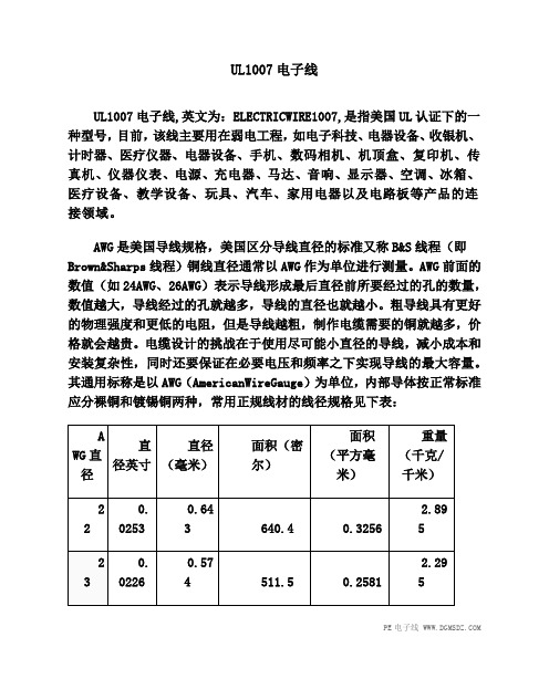
其通用标称是以AWG(AmericanWireGauge)为单位,内部导体按正常标准应分裸铜和镀锡铜两种,常用正规线材的线径规格见下表:。
氢氟酸HF浓度检测仪
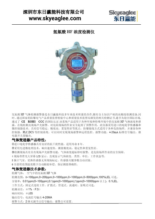
氢氟酸HF浓度检测仪氢氟酸HF气体检测报警器是东日瀛能科技多年来技术积累的杰作,拥有自主知识产权的高精度检测设备,同时、通过国家的防爆电气产品质量监督检验中心和质量技术监督局颁发的相关检测证书,通书为迎合国际市场,通过了CE ROHS CCC的国际认证.该系统产品适用于各种环境和特殊环境中的氢氟酸HF气体浓度和泄露,在线检测及现场声光报警,对危险现场的作业安全起到了预警作用,此仪器采用进口的电化学传感器和微控制器技术,具有信号稳定,精度高,重复性好等优点,防爆接线方式适用于各种危险场所,并兼容各种控制器,PLC,DCS等控制系统,可以同时实现现场报警和远程监控,报警功能,4-20mA标准信号输出,继电器开关量输出。
气体变送器产品特性:①进口电化学传感器具有良好的抗干扰性能,适用寿命8年。
②采用先进微处理技术,响应速度快,测量精度高,稳定性和重复性好。
③检测现场具有具有现场声光报警功能,气体浓度超标即时报警,是危险场所作业的安全保障。
4现场带背光大屏幕LCD显示,直观显示气体浓度,类型,单位,工作状态等。
5独立气室,更换传感器无须现场标定,传感器关键参数自动识别。
6全量程范围温度数字自动跟踪补偿,保证测量准确性。
气体变送器技术参数:检测气体:空气中的氢氟酸HF气体检测范围:0~100ppm,0~200ppm,0~1000ppm,0~1000ppm,0~5000ppm,100%LEL可选。
分别率:0.01ppm(0~100ppm);0.1ppm(0~1000ppm);1ppm(0~10000ppm以上);0.1LEL.工作方式:固定式连续工作,扩散式,管道式,流通时,泵吸式可选。
检测误差:≦1%(F.S)响应时间:≦10S输出信号:电流信号输出4-20MA报警方式:2路无源节点信号输出,报警点可设置。
工作环境:-20℃~50℃(特殊要求:(-40℃~+70℃)相对湿度:≦90%RH工作电压:DC12~30V传感器寿命:3年防爆形式:探头变送器及传感器均为隔爆型。
HFM107资料

FIG.2-TYPICAL FORWARD CURRENT DERATING CURVE
1.2 1.0 0.8 0.6 0.4 0.2 0 0
Single Phase Half Wave 60Hz Resistive Or Inductive Load
AMBIENT TEMPERATURE ( C)
.01
FIG.4-MAXIMUM NON-REPETITIVE FORWARD SURGE CURRENT
PEAK FORWARD SURGE CURRENT,(A)
30
.001 .4
.6
.8
1.0
1.2
1.4
1.6
1.8
24
FORWARD VOLT AGE,(V)
0.067(1.7) 0.060(1.5)
0.110(2.8) 0.094(2.4)
0.165(4.2) 0.150(3.8)
0.040(1.0) Typ.
0.040 (1.0) Typ.
Mechanical data
Case : Molded plastic, JEDE DO-214AC C Terminals : Solder plated, s olderable per MIL-STD-750, Method 2026 Polarity : Indicated by cathode band Mounting P osition : Any Weight : 0.0015 ouncTYPICAL JUNCTION CAPACITANCE
175
trr +0.5A
| | | | | | | |
JUNCTION CAPACITANCE,(pF)
dm1007说明书

目录机床概述 2机床的工作环境要求 3机床的主要技术参数 4工作台 6 主轴单元7主轴电机8松刀机构9垂向平衡装置10三向进给运动11气动系统13润滑系统14刀库及换刀机构 15刀具及可选附件16DM1007立式加工中心使用说明书DM1007是我单位与美国著名机床制造商DYNA集团公司合作生产的小型高精度立式加工中心。
DM1007立式加工中心是按照现代生产型加工中心的要求,结合中小零件的加工特点而设计的,具有现代机械制造业的高速度、高精度、高效率等特点,特别适合于仪器、仪表、模具、刀具、夹具等行业的铝合金、铜合金、不锈钢材料的精细孔、槽、面的加工。
通过选购NC转台和NC分度头可实现4、5轴控制,完成复杂曲面零件的高效率、高精度加工。
机床可根据用户要求配备各类数控系统,并参照用户提供的各类电机的接口尺寸进行特殊设计。
数控系统常规配置采用美国DYNA公司独立设计的数控系统DYDA PIII dyna,基本控制为三轴控制,并配有刚性攻丝能力,本机床机械结构可靠、合理,控制方式有效、灵活,采用精化设计、体积紧凑、占地面积小、重量轻,特别适合作为小批量、多品种零件的柔性生产线的加工单元。
机床外观图一、机床的工作环境要求机床电源:单相220V机床总功率:5KVA冷却系统:冷却液、固定专用水箱润滑系统:导轨、丝杠采用集中式自动润滑装置(专用润滑油N68)主轴轴承采用锂基润滑脂气动系统:洁净气源、公称压力0.55Mpa温度、抗震、抗干扰性:按金属切削机床国标规定、参照数控系统的有关要求二、机床的主要技术参数2.1主轴电机:额定功率: 1.49Kw额定扭矩:3Nm转速范围:0-6000rpm2.2进给电机:额定功率:0.23Kw额定转速:3000rpm2.3冷却泵:扬程:3m流量:25L/min2.4气源:额定压力:0.55MPa过滤精度:50μm2.5水平工作台:工作台尺寸:450mm×180mm面积:250mm×175mmT槽数量: 3T槽宽度:10mmT槽间距:50mm承重:60Kg2.6工作行程:纵向:240mm横向:165mm垂向:240mm2.7主轴:主轴转速:低速段:0-3000rpm高速段:3000-6000rpm主轴锥孔:ISO No.30 7:24额定扭矩:6/2.3 Nm松刀压力:300Kg刀具夹紧力:250Kg2.8三向进给速度:自动进给:0-5000mm/min手动/点动:1-1260mm/min最小进给量:0.001mm2.9三向快速进给速度:5000mm/min2.10机床定位精度:0.01mm2.11重复定位精度:0.006mm2.12主轴端部到工作台距离:95-345mm2.13主轴中心到床身导轨距离:210mm2.14刀库形式:自动刀具交换系统:斗笠式刀库容量:6把换刀方式:双向随机最大刀具长度:150mm最大刀具直径:φ150mm最大刀具重量:2Kg刀具交换时间:7sec(刀对刀)2.15机床外形:长×宽×高:1220×1110×1430mm 2.16机床重量:净重:550Kg三、工作台DM1007型立式加工中心工作台为安装工件及其它附件提供安装基础面,其结构及尺寸如图所示:图3.1水平工作台结构及尺寸简图该机床主轴采用ISO No.30 7:24锥孔,轴承选用日本NSK公司高精度主轴专用轴承,迷宫式密封,轴向固定采用油压螺母(装卸专用工具),采用气动松刀,松刀同时吹气以清洁主轴、蝶型弹簧复位拉紧。
1007线材标准

1007线材标准摘要:1.1007 线材标准的概述2.1007 线材标准的主要内容3.1007 线材标准的应用范围4.1007 线材标准的重要性正文:1.1007 线材标准的概述1007 线材标准,是我国电线电缆行业的一项重要标准,主要用于规范和指导线材产品的生产、检验和应用。
该标准以数字1007 命名,来源于我国国家标准GB/T 1007-2008《圆线同心绞架空导线》。
这一标准对线材的尺寸、结构、材料、力学性能、电性能等各方面都做了详细的规定,以确保线材的质量和性能达到一定的要求。
2.1007 线材标准的主要内容1007 线材标准的主要内容包括以下几个方面:(1)尺寸:规定了线材的直径、厚度等尺寸参数,以满足不同应用场景下线材的性能需求。
(2)结构:规定了线材的结构形式,如同心绞架空导线等,以提高线材的力学性能和电性能。
(3)材料:规定了线材的主要材料和辅助材料,如导体材料、绝缘材料、护套材料等,以确保线材的性能稳定。
(4)力学性能:规定了线材的拉伸强度、断裂伸长率等力学性能指标,以保证线材在使用过程中的稳定性和安全性。
(5)电性能:规定了线材的电阻、绝缘电阻、耐压等电性能指标,以确保线材的电传输效率和安全性。
3.1007 线材标准的应用范围1007 线材标准广泛应用于我国电力、通信、铁路、石油化工、航空航天等行业。
这些行业对线材的需求量大,且对线材的性能要求高,因此,1007 线材标准的实施对于保障这些行业的正常运行具有重要意义。
4.1007 线材标准的重要性1007 线材标准对于我国电线电缆行业的健康发展具有重要意义。
首先,该标准为线材的生产和检验提供了明确的技术依据,有利于提高线材的质量和性能。
其次,该标准有助于引导线材行业的技术进步,推动行业向高质量、高效益的方向发展。
最后,该标准为线材的应用提供了安全保障,有利于确保电力、通信等重要行业的稳定运行。
HFM108中文资料
8.3ms Single Half Sine-Wave (JEDEC Method)
50
40
30
20
10
0
1
2
5 10 20
50 100
NUMBER OF CYCLES AT 60Hz
JUNCTION CAPACITANCE, (pF)
FIG. 6 - TYPICAL JUNCTION CAPACITANCE 200
HFM101 THRU
HFM108
FEATURES
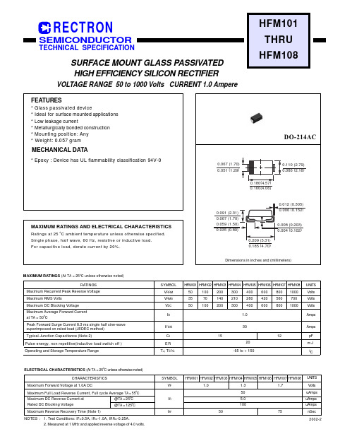
* Glass passivated device * Ideal for surface mounted applications * Low leakage current * Metallurgically bonded construction * Mounting position: Any * Weight: 0.057 gram
SYMBOL VF
IR
trr
HFM101 HFM102 HFM103 HFM104 HFM105 HFM106 HFM107 HFM108 UNITS
1.0
1.3
1.7
Volts
50
uAmps
5.0
uAmps
100
uAmps
50
75
nSec
2002-2
元器件交易网
RATING AND CHARACTERISTIC CURVES ( HFM101 THRU HFM108 )
@TA = 125oC
Maximum Reverse Recovery Time (Note 1)
NOTES : 1. Test Conditions: IF=0.5A, IR=-1.0A, IRR=-0.25A. 2. Measured at 1 MHZ and applied reverse voltage of 4.0 volts.
泰美电子1006直流毫伏源和1007直流毫伏电位计 源用户手册说明书
User Manual1006 DC Millivolt Sourceand1007 DC Millivolt Potentiometer/SourceVersion 1.29-22Time Electronics LtdUnit 5, TON Business Park, 2-8 Morley Road,Tonbridge, Kent, TN9 1RA, United Kingdom.T: +44 (0) 1732 355993 | F: +44 (0) 1732 350198***********************.uk|© 2022 Time Electronics Ltd.All rights reserved.Nothing from this manual may be multiplied, or made public in any form or manner, either electronically or hard copy, without prior written consent from Time Electronics Ltd. This also applies to any schematics, drawings and diagrams contained herein.This manual provides operating and safety instructions for the Time Electronics product. To ensure correct operation and safety, please follow the instructions in this manual. Time Electronics reserves the right to change the contents, specifications and other information contained in this manual without notice.Contents1Introduction (4)1.11006 DC Millivolt Source (4)1.21007 DC Millivolt Potentiometer and Source (5)1.3Specifications (6)2Controls (7)2.11006 Controls (7)2.21007 Controls (8)3Operating Instructions (9)3.1Battery Insertion (9)3.21006/1007 mV Source Operation (9)3.31007 mV Potentiometric Null Operation (10)4Servicing and Calibration (11)4.1Internal Preset Controls (11)4.2Calibration and Adjustment (11)5Warranty and Servicing (14)1Introduction1.11006 DC Millivolt SourceFeatures• 3 ranges:0 to 999.9mV (0.1 mV steps)0 to 99.99mV (10 µV steps)0 to 9.999mV (1 µV steps)•Accuracy 0.02 %•20 mA output current•Short circuit and overload protected•Safety terminals•Removable protective cover•Powered by 6 x AA batteries•100 hours typical battery life•Optional carry caseDescriptionThe 1006 is an accurate millivolt source suitable for voltage injection applications.Three output ranges are provided to give adjustable output values from 1 µV to 1 V with a basic 0.02 % accuracy. For signal injection, the operator needs to switch on, check the battery condition, select the range, and set the required voltage using the thumbwheel switches. The 1006 uses a precision bandgap reference device, with low temperature coefficient resistors to give a highly stable output.Power is provided by 6 AA batteries. Battery life is several months, depending on usage. The battery condition is monitored by an indicator situated on the top of the unit.The 1006 has up to 20 mA drive current and is short circuit and overload protected.An off/normal/reverse output polarity switch is provided.Connection is via safety terminals that are compatible with 4 mm shrouded plugs, as well as standard plugs, bare wires, and spade terminals.The unit comes fitted with an ergonomic rubber cover providing increased protection and durability. It has a textured grip for comfortable handling and top/bottom openings to place labels. It is easy to remove if the user prefers a stand-alone unit or to house the instrument in the optional carry case.The unit is simple to operate and does not require standardisation or calibration prior to use.1.21007 DC Millivolt Potentiometer and SourceFeatures• 3 ranges:0 to 999.9mV (0.1 mV steps)0 to 99.99mV (10 µV steps)0 to 9.999mV (1 µV steps)•Accuracy 0.02 %• 1 µV resolution null•20 mA output current•Short circuit and overload protected•Safety terminals•Removable protective cover•Powered by 6 x AA batteries•100 hours typical battery life•Optional carry caseDescriptionThe 1007 includes all the features of the 1006 with the addition of a microvolt null balance display. This enables it to be used for potentiometric voltage measurement in addition to its function as a calibrator. The null zero and sensitivity are adjustable via front panel controls - maximum sensitivity enables null balance to resolve 1 µV.Applications are essentially those of conventional potentiometers with the following significant advantages:•No standardisation is required.•20 mA output current.•Output remains stable without re-adjustment.•Electronic null with microvolt sensitivity.Connection is via safety terminals that are compatible with 4 mm shrouded plugs, as well as standard plugs, bare wires, and spade terminals.The unit comes fitted with an ergonomic rubber cover providing increased protection and durability. It has a textured grip for comfortable handling and top/bottom openings to place labels. It is easy to remove if the user prefers a stand-alone unit or to house the instrument in the optional carry case.The 1007 is simple to operate and does not require standardisation or calibration before use. It is only necessary to zero the null amplifier prior to making a measurement.1.3SpecificationsOutput:0 to999.9 mV in 3 ranges:0 to 999.9 mV in 0.1 mV steps0 to 99.99 mV in 10 μV steps0 to 9.999 mV in 1 μV stepsAccuracy:± (0.02 % of setting + 0.02 % of range + 1 μV)Output Resistance:Less than 0.2 Ω on 1 V and 100 mV ranges. 1 Ω on 10 mV range. Maximum Output Current:999.9mV and 99.99mV ranges: 20 mA.9.999mV range: Up to short circuit value although it should benoted that loads of less than 1 kΩ will give greater than 0.1 % error. Output Voltage Stability:Less than 60 ppm/°C.Less than 100 ppm per 3 month. (non cumulative)Operating Temperature:-10 °C to + 60 °C.Output Polarity:Positive or negative switch selected. A centre ‘off’ position is also provided. Output Noise Level:Less than 30 ppm of full scale.Reference Source: A precision bandgap reference diode is used to provide stability witha low temperature coefficient.Maximum Overload:The instrument can withstand continuous short circuit on the outputfor all ranges.Power Supply: 6 AA batteries. A battery condition monitor indicates when thebatteries should be replaced. An alternative power source is 6 NiMHcells of the same dimensions - these can be recharged via the chargesocket located on the top of the unit. The 6 rechargeable batteriesand mains re-charger unit are available as an optional extra.Null Balance Display: The null function is displayed on a front panel twin coloured LED bar (1007 only) graph, zero and sensitivity controls are provided.•Maximum sensitivity: ± 20 µV fsd•Minimum sensitivity: ± 200 mV fsd•Input resistance: Greater than 1 MΩ at balance. Dimensions:200 x 75 x 110 mm (215 x 100 x 120 mm incl. protective cover). Weight:0.75 kg (1.2 kg incl. protective cover).Options:9027 carry case (user must remove protective cover).9529 rechargeable battery pack (6 cells and mains charger).2Controls2.11006 Controls2.21007 ControlsThe 1007 incorporates a 1006 with the addition of a microvolt null detector and enables the unit to be used for potentiometric measurements. The additional components are highlighted with green boxes below.3Operating Instructions3.1Battery InsertionTo insert batteries, remove two black covers on top of theinstrument by pressing in and turning 90° anti-clockwise.Three size AA batteries should be inserted in each tube withthe positive (tip) terminal upmost.Note that if the optional battery charger is to be used, thennickel metal hydride (NiMH) rechargeable batteries must beused in the instrument.3.21006/1007 mV Source OperationTo operate both models as a mV source, follow the steps below:POLARITY SWITCH NOTE:On the 1006, the “off” polarity position disconnects the output & provides a short circuit on the output terminals. On the 1007, the “off” polarity position provides an open circuit on the output terminals. This is to prevent accidental shorting of the voltage under test when the unit is being used as a potentiometer. It is desirable to keep the Null “SENSITIVITY” control set to minimum (fully anti-clockwise) when the 1007 is used as a source.3.31007 mV Potentiometric Null OperationDue to the extreme sensitivity of the electronic null detector (3 µV/div.) it is important to ensure that it is correctly zeroed before attempting accurate measurements.3.3.1Zero Setting Procedure3.3.2Measuring Procedure4Servicing and Calibration4.1Internal Preset ControlsIMPORTANT NOTE:These controls are set in the factory before shipment and normally will not require readjustment.If readjustment is considered necessary, it is important to check that the amount of adjustment required is within the range of the trimmer concerned. If it is greater than the trimmer range, there is no point in attempting to readjust and a fault condition will exist in the unit. The range of adjustment of the trimmers is given below. Access to the 1006 or 1007 is by removing the blue case cover which is located by 8 screws.1006 DC mV SourceThe 1006 contains 4 (3 on instruments with serial number earlier than 1320) internal preset trimmers. They are located on the range switch selector module.Zero TrimmerThe ‘ZERO’ trimmer adjusts the circuit zero and is set to bring the output voltage (with all digits set to zero) within the specified limits.Calibration TrimmersThe 1 V, 100 mV, and 10 mV ‘CAL’ trimmers adjust the full-scale calibration (i.e. 9999) on all 3 ranges respectively to within the specified limits.It is important to set the ZERO before attempting calibration.4.2Calibration and AdjustmentTest Equipment Required1) A microvoltmeter with a resolution of better than 5 microvolts.2) An accurate DC voltage source with a range 0 to 1 V, accuracy better than 0.02 %.Zero Setting ProcedureSwitch unit on and check battery condition is good.1) Select 99.99 mV range and set all digits to zero.2) Select ‘NORMAL’ output polarity.3) Connect microvoltmeter to output and adjust ZERO trimmer for less than 10 µV reading.The maximum amount of adjustment available on this trimmer is approximately ± 100 µV.5)Check the zero reading for all three ranges. The readings should be as follows:9.999 mV range less than ± 2 µV99.99 mV range less than ± 10 µV999.9 mV range less than ± 100 µVFS Calibration/Adjustment Procedure1) Check zero output is correct as described earlier.2)Select 999.9 mV range and ‘normal’ output polarity.3)Set output digits to 9999.4)Connect the accurate voltage source and microvolt null meter to the 1006 output in apotentiometric mode.5) Set the voltage source to 999.9 mV output and adjust the ‘1V CAL’ trimmer on the moduleto bring the 1006 output within specification. The maximum amount of adjustmentavailable on this trimmer is 0.8 %.6) Select 99.99 mV range on the 1006 and set the voltage source to 99.99 mV. Adjust the‘100mV CAL’ trimmer to bring the output within specification. The maximum amount of adjustment available on this trimmer is 0.8 %.7) Select the 9.999mV range on the 1006, and set the voltage source to 9.999 mV. Adjustthe ‘10mV CAL’ trimmer bring the output to within specification. The maximum amount of adjustment available using this trimmer is 0.8%.8)The specified FS allowable errors for these three ranges are:999.9mV range less than ± 550uV at full scale output.99.99mV range less than ± 55uV at full scale output.9.999mV range less than ± 6uV at full scale output.Note: All instruments with serial numbers earlier than 1320 do not have the additional trimmer fitted to adjust the 9.999mV full scale calibration of the 10mV range. See item 9 below.9)The 9.999mV range is obtained by resistive attenuation of the 999.9mV range. A 100:1 attenuation ratio is used and adjustment is by preselected resistor values. Unless overload damage to the attenuator resistors has occurred, the calibration of the 1-volt range will automatically ensure the full scale calibration of the 9.999mV range.1007 Millivolt Source and PotentiometerThe 1007 incorporates a 1006 with the addition of a microvolt null detector. With the front panel function switch in the ‘SOURCE’ position, the unit operates as a 1006 and the ZERO and CALIBRATION setting procedures are identical to those for the 1006.The potentiometer position of the function switch connects a high performance null balance system in series with the output. The null zero and sensitivity are adjustable by front panel controls. Maximum sens. = ± 20 µV. Min. sens. = ± 200 mV and zero adjust range is approximately ± 100 µV.The null amplifier circuitry is located on a small pcb which is fixed to the underside of the output terminals. The circuitry incorporates two preset trimmers for adjustment of the null amplifier input voltage and current offsets.Important Note: It is important to check that the 1007 is operating correctly as a millivolt source and that the source zero setting is within specification before considering readjustment of the null amplifier trimmers.Null Amplifier trimmer adjustment procedureVoltage Offset (10k trimmer):1) Select ’ZERO’ position on the function switch.2) Set all digits to zero. Select 9.999 mV range.3) Adjust trimmer for equal swing (about zero) of the front panel zero control.Current Offset (500k trimmer):1) Select ’ZERO’ function, all digits zero, 9.999 mV range.2) Select potentiometer operation.3) Connect a 47 kilohm resistor across output terminals.4) Set the null sensitivity control to minimum.5) Adjust trimmer for zero reading on the null display - the null sensitivity can be increased gradually to maximum during adjustment.Note: A low offset current is important when measurements are to be made in high resistance circuits, but will not affect accuracy of measurements in low resistance circuits.5Warranty and ServicingWarrantyTime Electronics products carry a one-year manufacturer’s warranty as standard.Time Electronics products are designed and manufactured to the highest standards and specifications to assure the quality and performance required by all sectors of industry. Time Electronics products are fully guaranteed against faulty materials and workmanship.Should this product be found to be defective, please contact us using the below details. Inform us of the product type, serial number, and details of any fault and/or the service required. Please retain the supplier invoice as proof of purchase.This warranty does not apply to defects resulting from action of the user such as misuse, operation outside of specification, improper maintenance or repair, or unauthorized modification. Time Electronics’ total liability is limited to repair or replacement of the product. Note that if Time Electronics determine that the fault on a returned product has been caused by the user, we will contact the customer before proceeding with any repair.Product RegistrationYou can register your product at: /contact/product-registration Registering your product will enable us to maintain a record of purchase for your warranty. You can also use the web form to provide feedback about our products and services. Calibration and Repair ServicesTime Electronics offers repair and calibration services for all the products we make and sell. Routine maintenance by the manufacturer ensures optimal performance and condition of the product. Periodic traceable or accredited calibration is available.Contacting Time ElectronicsOnline:Please visit and select Technical Support from the Contact links. From this page you will be able to send information to the Time Electronics service team who will help and support you.By phone:+44 (0) 1732 355993By email:***********************.ukReturning InstrumentsPrior to returning your product please contact Time Electronics. We will issue a return merchandise authorization (RMA) number that is to accompany the goods returning. Further instructions will also be issued prior to shipment. When returning instruments, please ensure that they have been adequately packed, preferably in the original packing supplied. Time Electronics Ltd will not accept responsibility for units returned damaged. Please ensure that all units have details of the service required and all relevant paperwork.Send the instrument, shipping charges paid to:Time Electronics LtdUnit 5, TON Business Park, 2-8 Morley Road,Tonbridge, Kent, TN9 1RA.United Kingdom.Tel: +44(0)1732 355993Fax: +44(0)1732 350198Email:***********************.ukWeb Site: Disposal of your old equipment1. When this crossed-out wheeled bin symbol is attached to a product it means the product iscovered by the European Directive 2002/96/EC.2. All electrical and electronic products should be disposed of separately from the municipalwaste stream via designated collection facilities appointed by the government or the localauthorities.3. The correct disposal of your old appliance will help prevent potential negative consequencesfor the environment and human health.4. For more detailed information about disposal of your old appliance, please contact your cityoffice, waste disposal service or return to Time Electronics.。
HX1007中文资料

RF Monolithics, Inc.Phone: (972) 233-2903Fax: (972) 387-9148E-mail: info@ Page 1 of 2RFM Europe Phone: 44 1963 251383Fax: 44 1963 251510 ©1999 by RF Monolithics, Inc. The stylized RFM logo are registered trademarks of RF Monolithics, Inc.HX1007-101999Electrical CharacteristicsCharacteristicSym Notes Minimum TypicalMaximum Units Operating FrequencyAbsolute Frequency f O 1, 2, 3, 4,10433.72434.12MHz Tolerance from 433.92 MHz∆f O ±200kHz RF Output Power into 50 Ω at 25°CP O2, 4, 5, 10-30dBm Within Specified Temperature Range2, 3, 4, 5-50Harmonic Spurious Emissions 2, 3, 4, 5-40dBc Modulation InputInput HIGH Voltage V IH 3, 4, 52.5V CC V Input LOW Voltage V IL 0.00.3Input HIGH Current I IH 100µA Input LOW CurrentI IL 0.0Data Timing Parameters Modulation Rise Time t R 3, 4, 5, 612µs Modulation Fall Time t F 10Power SupplyVoltage V CC 5, 7 2.73 3.3VDC Peak Current I CC3, 4, 5, 8710mA Standby Current5, 9 1.0µA Operating Case Temperature RangeT C 5-40+85°CLid Symbolization (in addition to Lot and/or Date Codes)RFM HX1007SM-4 Case•Ideal for 433.92 MHz Unlicensed Transmitters in Europe •Quartz SAW Frequency Stabilization and Harmonic Filtering •Compact, Surface-Mount Case with <90mm 2 FootprintThe HX1007 is a miniature hybrid transmitter designed for data transmission using on-off keyed (OOK) mod-ulation. The transmitter is stabilized by a quartz SAW device for long-term frequency stability. The HX1007 is recommended for data rates up to 19.2kbps (52µsec bit period). The HX1007 is designed for unlicensed control, secuirty and data links certified and operating under ETSI-I-ETS 300 200 regulations.Absolute Maximum RatingsRatingValue Units Power Supply and/or Modulation Input Voltage 10V Nonoperating Case Temperature -40 to +85°C Ten-Second Soldering Temperature230°C433.92 MHz Hybrid TransmitterHX1007CAUTION: Electrostatic Sensitive Device. Observe precautions for handling.NOTES:1.One or more of the following United States patents apply: 4,454,488; 4,616,197; 4,670,681; and 4,760,352.2.Typically, equipment utilizing this device requires emissions testing and government approval, which is the responsibility of the equipment manufac-turer.3.Applies over the specified range of operating temperature.4.Applies over the specified range of operating power supply voltage.5.The design, manufacturing process, and specifications of this device are subject to change without notice.6.The maximum modulation bandwidth (and data rate) is dependent on the characteristics of the external encoding circuitry (not included).7.Unless noted otherwise, case temperature T C = +25°C ± 2°C, test load impedance = 50 Ω, and modulation input is at logic HIGH.8.The maximum operating current occurs at the maximum specified power supply voltage and maximum specified operating temperature.9.Standby current is defined as the supply current consumed with the modulation input at logic LOW.10.Improper antenna loading affects performance of HX device.433.92 MHz Hybrid TransmitterRF Monolithics, Inc.Phone: (972) 233-2903Fax: (972) 387-9148E-mail: info@ Page 2 of 2RFM Europe Phone: 44 1963 251383Fax: 44 1963 251510 ©1999 by RF Monolithics, Inc. The stylized RFM logo are registered trademarks of RF Monolithics, Inc.HX1007-101999Electrical ConnectionsBlock DiagramCase DesignFootprintTypical Test Circuit*Note: Bypass required only for “HX2...” series transmitters in the 902 to 928 MHz band.Typical Transmitter ApplicationNotes:1.This matching component is required only for antennas that are not 50 ohms. It is typically a chip inductor to match to stub antennas shorter than ¼ wavelength. For very low radiated field-strength appli-cations, a resistor can also be used.2.For ESD protection.Terminal NumberConnections 1Data Input 2+DC Supply 3Ground 4RF Output to 50 ΩDimensionsMillimeters InchesMinMax MinMax A 10.670.420B 1.27 Nominal 0.050 NominalC 2.67 Nominal 0.105 NominalD 5.08 Nominal 0.200 NominalE 1.70 Nominal 0.067 NominalF 5.36 Nominal0.211 NominalG 2.800.110H9.020.355C。
常熟本安仪表系统有限公司介绍企业发展分析报告模板

Enterprise Development专业品质权威Analysis Report企业发展分析报告常熟本安仪表系统有限公司免责声明:本报告通过对该企业公开数据进行分析生成,并不完全代表我方对该企业的意见,如有错误请及时联系;本报告出于对企业发展研究目的产生,仅供参考,在任何情况下,使用本报告所引起的一切后果,我方不承担任何责任:本报告不得用于一切商业用途,如需引用或合作,请与我方联系:常熟本安仪表系统有限公司1企业发展分析结果1.1 企业发展指数得分企业发展指数得分常熟本安仪表系统有限公司综合得分说明:企业发展指数根据企业规模、企业创新、企业风险、企业活力四个维度对企业发展情况进行评价。
该企业的综合评价得分需要您得到该公司授权后,我们将协助您分析给出。
1.2 企业画像类别内容行业空资质增值税一般纳税人产品服务仪表及控制系统的开发、销售及相关技术服务;1.3 发展历程2工商2.1工商信息2.2工商变更2.3股东结构2.4主要人员2.5分支机构2.6对外投资2.7企业年报2.8股权出质2.9动产抵押2.10司法协助2.11清算2.12注销3投融资3.1融资历史3.2投资事件3.3核心团队3.4企业业务4企业信用4.1企业信用4.2行政许可-工商局4.3行政处罚-信用中国4.4行政处罚-工商局4.5税务评级4.6税务处罚4.7经营异常4.8经营异常-工商局4.9采购不良行为4.10产品抽查4.11产品抽查-工商局4.12欠税公告4.13环保处罚4.14被执行人5司法文书5.1法律诉讼(当事人)5.2法律诉讼(相关人)5.3开庭公告5.4被执行人5.5法院公告5.6破产暂无破产数据6企业资质6.1资质许可6.2人员资质6.3产品许可6.4特殊许可7知识产权7.1商标7.2专利7.3软件著作权7.4作品著作权7.5网站备案7.6应用APP7.7微信公众号8招标中标8.1政府招标8.2政府中标8.3央企招标8.4央企中标9标准9.1国家标准9.2行业标准9.3团体标准9.4地方标准10成果奖励10.1国家奖励10.2省部奖励10.3社会奖励10.4科技成果11土地11.1大块土地出让11.2出让公告11.3土地抵押11.4地块公示11.5大企业购地11.6土地出租11.7土地结果11.8土地转让12基金12.1国家自然基金12.2国家自然基金成果12.3国家社科基金13招聘13.1招聘信息感谢阅读:感谢您耐心地阅读这份企业调查分析报告。
大汉 4100 型 HF 无线 FAX 数据调制解调器使用手册说明书
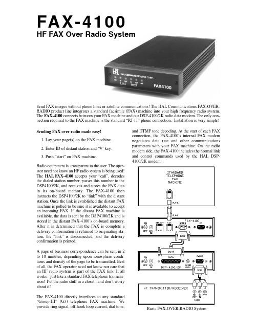
Send FAX images without phone lines or satellite communications! The HAL Communications FAX-OVER-FAX-4100HF FAX Over Radio SystemBasic FAX-OVER-RADIO SystemSYSTEM COMPONENTS:The HAL FAX-OVER-RADIO S ystem is simple and makes maximum use of your G3 FAX machine and SSB HF station. Add the DSP-4100 and FAX-4100 and you’re on-the-air with FAX.Virtually all modern S S B HF transceivers may be used for FAX. The 500 to 2500 Hz spectra of CLOVER-2000 is directly compatible with S S B radio passbands. Special bandwidth filters or super phase-linear filters are not required. The +50 Hz fre-quency tolerance is compatible with virtually all modern synthesized S S B equipment. S tandard 100Watt transmitters and simple antennas (1/2 wave dipoles or 1/4 wave verticals) are all that is needed for most FAX-OVER-RADIO links.Note that all HAL units operate from “nominal”12VDC (10 to 18 VDC, in fact). The HAL FAX-OVER-RADIO system is a very good choice forCOMPUTERS & OTHER EXPANSION:The basic FAX-OVER-RADIO system does not require a computer at either end. All control func-tions and data communications are handled within the HAL FAX-4100 and DSP-4100/2K. This makes for a very low-cost and simple system for remote areas where a computer is not required nor desired. However, a computer can easily be added to the communications link. This allows use of CLOVER-2000 for all forms of data. If you wish to design cus-tom software, the computer may also be used for fur-ther data compression, communicationwith the radio control port, or other control functions. The DS P-4100/2K includes a second serial I/O port which may be used to connect to the control port of the HF radio, eliminating the need for a second serial port from the computer - a serious problem for lap-top PC’s. Standard phone line and data circuit connec-tors are used to keep installation simple.。
ul1007线材载流标准
"ul1007线材载流标准"可能是指UL 1007标准,这是一种美国电气认证标准,主要用于评估电子设备中使用的电线和电缆的性能。
UL 1007标准主要关注以下几个方面:
1. 温度等级:UL 1007标准规定了电线和电缆在不同温度下的使用条件。
这些温度等级通常分为90℃、105℃和125℃等。
2. 绝缘材料:UL 1007标准要求电线和电缆的绝缘材料具有良好的耐热性、耐油性和耐化学腐蚀性。
3. 导体材料:UL 1007标准规定了导体材料的最小截面积和电阻值,以确保电线和电缆在特定电流下的正常工作。
4. 机械性能:UL 1007标准要求电线和电缆具有一定的抗拉强度、抗压强度和抗弯曲性能,以确保在安装和使用过程中不会发生断裂或变形。
5. 环境适应性:UL 1007标准要求电线和电缆能够适应各种恶劣的环境条件,如高温、高湿、紫外线辐射等。
6. 安全性:UL 1007标准要求电线和电缆在正常使用和故障情况下不会产生危险的电火花或热量,以确保用户的安全。
总之,UL 1007线材载流标准是一种评估电线和电缆性能的标准,主要关注其温度等级、绝缘材料、导体材料、机械性能、环境适应性和安全性等方面。
- 1、下载文档前请自行甄别文档内容的完整性,平台不提供额外的编辑、内容补充、找答案等附加服务。
- 2、"仅部分预览"的文档,不可在线预览部分如存在完整性等问题,可反馈申请退款(可完整预览的文档不适用该条件!)。
- 3、如文档侵犯您的权益,请联系客服反馈,我们会尽快为您处理(人工客服工作时间:9:00-18:30)。
2
1
1±0.15 1±0.15 2.0max.
4
5
6 0.6
HFM3000 SERIES(VCC LESS TYPE OF HIGHLY RATIONALIZATION DESIGN FOR OPTICAL PICKUP) HFM3500 SERIES(AS ORIGINAL DRIVER CIRCUIT, SUITABLE TO TWO-WAVELENGTH SEMICONDUCTOR LASER WITH SINGLE PART) SHAPES AND DIMENSIONS/TERMINAL CONNECTION/RECOMMENDED PC BOARD PATTERN(REFLOW)
I-L CHARACTERISTICS (TYPICAL)
6 Optical output P0 (mW) 5
MEASURING CIRCUIT
Laser diode PD Vcc
Vcc-∆lop CHARACTERISTICS (TYPICAL)
4
Optical power meter
3 HFM on 2 HFM off 1 0 0 5 10 15 20 25 30 35 Operating current Iop (mA) 40
3.2±0.3 3 2 1 2.5±0.3 OUT GND (LD) GND 5 6 4 3 1.0 1.0 1.0 3 Vcc IN 2 Oscillation circuit 3.7 Matching circuit 4 Dimensions in mm APC driver Weight: 50mg typ. 0.55±0.2 Dimensions in mm 5 OUT (LD) Iop 6 1
Oscillation frequency(MHz)
Oscillation output(dBm)
340 330 320 310 300 –20 0 20 40 60 Temperature(˚C) 80
–2 –3 –4 –5 –6 –7 –20 0 20 40 60 Temperature(˚C) 80
L(Beads) X Current source Y X-Y recorder
∆Iop (mA)
4
HFM
LD
3 2 1 0
3.3V type 5V type
0
1 2 3 4 5 Power supply voltage Vcc (V)
6
TEMPERATURE CHARACTERISTICS EXAMPLES Each characteristic was measured after thermal equilibration at the test temperature in an isothermal tank.
HFM1000 SERIES(3225 CHIP TYPE : SUITABLE FOR ALL SEMICONDUCTOR LASERS) SHAPES AND DIMENSIONS/TERMINAL CONNECTION/RECOMMENDED PC BOARD PATTERN(REFLOW)/CIRCUIT DIAGRAM
TYPICAL APPLICATIONS DVD PLAYER BLOCK DIAGRAM
RF Modules
PC/MPEG-Board HFM Optical pickup Phase equalizer Demodulator Error corrector MPEG2 decoder Video D/A converter NTSC/PAL encoder OUTPUT LPF RGB CPU Audio circuit Audio D/A converter L R Y C CVS
3.2±0.3 3 2 1 2.5±0.3 OUT GND (LD) GND 5 6 4 3 1.0 1.0 1.0 1.0 3.7 3 GND
(from APC)
2
1
4
56Leabharlann 1±0.15 1±0.15 2.0max.
2 IN
1 GND
4
5
6 0.6
1.0
4
5
6
3 2 1 GND Vcc GND
Dimensions in mm
LEAD-FREE SOLDER: Sn-3Ag-0.5Cu
10s max. 250˚C 230˚C 180˚C 150˚C Preheating: 120s max. Time(s) Natural cooling 60s max.
Preheating: 120s max. Time(s)
• All specifications are subject to change without notice.
Weight: 35mg typ. 0.55±0.2 Dimensions in mm
CIRCUIT DIAGRAM HFM3000 SERIES
APC driver Iop
HFM3500 SERIES
Two-wavelength APC driver DVD CD
3
IN 2 EMC filter Oscillation circuit Matching circuit
Operating current(mA)
350
–1
10 9 8 7 6 5 –20 0 20 40 60 Temperature(˚C) 80
RECOMMENDED REFLOW SOLDERING CONDITIONS EUTECTIC SOLDER
10s max. 230˚C 200˚C 180˚C 150˚C 40s max. 240˚C Natural cooling
DVD ROM Remote control I/O Interface
Memory
OPTICAL PICKUP CIRCUIT ARCHITECTURE
Regenerative signal Demodulation circuit Preamplifier Linear motor Photo detector Auto-focusing auto-tracking servo circuit Optical head Laser diode LD PD 2-axis actuator Disk APC driver Linear motor Disk rotation servo circuit Track detection circuit Radial servo circuit APC driver Vcc HFM HFM1000 Laser diode LD PD HFM3000 HFM
FEATURES • Within a multilayer ceramic substrate, these SMD type high frequency current superimposition modules each provide miniaturized high stability LC oscillation circuit elements. APPLICATIONS Pickup for MD, DVD, DVD-R, DVD-RAM, etc. LAYERED MODULE CONSTRUCTION(HFM1000)
1 Cop1
HFM
Cop2
LD PD LD
Vcc
HFM3500
4
5 OUT (LD)
6
• All specifications are subject to change without notice.
元器件交易网
(2/3) 001-01 / 20030402 / e8311_hfm.fm
HFM Series HFM1000, 3000, 3500 High Frequency Current Superimposition Modules For Optical Pickup
ELECTRICAL CHARACTERISTICS
Part No. HFM1000 series HFM-1057 HFM-1046 HFM-1114 HFM-1007 HFM3000 series HFM-3008 • Ta:20±5°C Oscillation frequency (MHz) 325±35 305±35 425±35 425±35 360±40 Power source voltage (V) 3.3 5 3.3 5 2.3
Minimold transistor Chip resistor Chip capacitor
RF Modules
Ceramic multilayer substrate containing high stability oscillation circuit(5×C/L×1) Terminal electrode
元器件交易网
(3/3) 001-01 / 20030402 / e8311_hfm.fm
HFM Series HFM1000, 3000, 3500 High Frequency Current Superimposition Modules For Optical Pickup
元器件交易网
(1/3) 001-01 / 20030402 / e8311_hfm.fm
HFM Series HFM1000, 3000, 3500 High Frequency Current Superimposition Modules For Optical Pickup
Motor
• All specifications are subject to change without notice.
RF Modules
MEASURING CIRCUIT
